


PHIS 1000 S
Assembly Instruction

Contents
1 Safety regulations and notes ........................................................................4
2 General information ....................................................................................5
2.1 Packing contents ............................................................................5
2.2 Meaning of the symbols used ..........................................................5
2.3 Technical data ...............................................................................5
2.4 Description ...................................................................................6
2.5 Software query..............................................................................7
3 Assembly ....................................................................................................8
3.1 Installing the cassette......................................................................8
3.2 EMC regulations ............................................................................9
3.3 Cassette overview........................................................................10
3.4 Connecting the cassette ................................................................10
3.5 Retrofitting a CA module ..............................................................11
4 The control panel at a glance ..................................................................... 12
4.1 Menu items .................................................................................12
4.2 Control panel ..............................................................................12
5 Programming ............................................................................................ 13
5.1 Overview ...................................................................................13
Function "Virtual Station Tables" ....................................................13
Programming via station tables.................................................13
5.2
Programming procedure ...................................................................14
5.3 Creating station tables .................................................................17
The structure of the text file for programming station tables ...............18
5.4 Uploading the station tables to the cassettes ....................................22
5.5 Programming the cassette .............................................................23
Selecting the cassette ...................................................................23
Selecting the station table .............................................................24
Setting the Ethernet parameters .....................................................24
Setting the hardware IP address of the cassette ...............................25
Setting the address range .............................................................26
Setting the address of the gateway ................................................26
Setting the UDP port ...................................................................... 27
Selecting the input data stream ......................................................27
LNB oscillator frequency / control voltage ......................................28
LNB oscillator frequency ..........................................................28
DiSEqC commands .................................................................28
Setting the input symbol rate .........................................................29
- 2 - PHIS 1000 S

Setting the DVB mode ..................................................................30
Setting the input frequency ............................................................30
Setting the output parameters ........................................................32
Setting the IP addresses for the outputs ...........................................33
Switching the IP address off or on ..................................................34
Selecting the transmission protocol .................................................34
Setting the port number ................................................................34
Defining the quantity of data packets .............................................35
Setting the forward error correction ...............................................35
Setting the transmission channel ....................................................35
Setting the output data rate ...........................................................36
Allocating services manually .........................................................37
Selecting the sound options of the service .......................................38
Automatic/Manual PIDs ...............................................................38
Switching DVB service information on or off....................................39
Stuffing the output data rate ..........................................................40
Displaying the output data rate......................................................40
Factory reset ...............................................................................41
Saving settings ............................................................................41
Operation with a CA module ........................................................42
Setting the PID monitoring ........................................................42
Configuring the CA module .....................................................42
Descrambling services .............................................................44
6 Final procedures ........................................................................................ 45
- 3 - PHIS 1000 S

1 safety regulations and notes
• Assembly, installation and servicing should be carried out by authorised
electricians.
• Switch off the operating voltage of the system before beginning with assembly or service work or pull out the mains plug.
• Do not perform installation and service work during thunderstorms.
• Install the system so it will not be able to vibrate…
- in a dust-free, dry environment
- in such a manner that it is protected from moisture, fumes, splashing wa-
ter and dampness
- somewhere protected from direct sunlight
- not within the immediate vicinity of heat sources
- in an ambient temperature of 0 °C to +50 °C. In case of the formation of
condensation wait until the system is completely dried.
• Ensure that the head-end station is adequately ventilated. Do not cover the
ventilation slots.
• Beware of short circuits
• No liability is accepted for any damage caused by faulty connections or
inappropriate handling.
• Observe the relevant standards, regulations and guidelines on the installation and operation of antenna systems.
• The standards EN/DIN EN 50083 and IEC/EN/DIN EN 60728 must be
observed.
• For further information please read the assembly instructions for the headend station used.
• Test the software versions of the head-end station and the cassette and
update them if necessary. The current software versions can be found at
"www.mygss.eu".
Take action to prevent static discharge when working on the device!
Electronic devices should never be disposed of in the household rubbish. In
accordance with directive 2002/96/EC of the European Parliament and the
European Council from January 27, 2003 which addresses old electronic and
electrical devices, such devices must be disposed of at a designated collection
facility. At the end of its service life, please take your device to one of these
public collection facilities for proper disposal.
- 4 - PHIS 1000 S

2 general information
2.1 PaCk ing Co ntents
1 Cassette PHIS 1000 S 2 RF cables
1 LAN cable 2 F jack-to-jack adapter
4 Lock washers 2 Thin nuts
1 Brief assembly instructions 1 Measuring log
2.2 meani ng of t h e sym b ols us e d
Important note
—> General note
• Performing works
2.3 teChniCal da ta
The devices meet the following EU directives:
2011/65/EU, 2014/30/EU, 2014/35/EU
The product fulfils the guidelines and standards for CE labelling (page 46).
Unless otherwise noted all values are specified as "typical".
RF input
Frequency range: ....................................................... 925 … 2150 MHz
Level range: ............................................................ 60 dBμV … 80 dBμV
Return loss: ..................................................................................> 8 dB
DVB-S modes: ............................................ QPSK 1/2 , 2/3 , 3/4 , 5/6 , 7/8
DVB-S2 modes: ...................QPSK 1/2 , 3/5 , 2/3 , 3/4 , 4/5 , 5/6 , 8/9 , 9/
8PSK 3/5 , 2/3 , 3/4 , 5/6 , 8/9 , 9/
10
10
Symbol rate DVB-S: .......................................... QPSK: 2 … 45 MSymb/s
Symbol rate DVB-S2: ........................................ QPSK: 10 … 30 MSymb/s
8PSK: 10 … 31 MSymb/s
LNB control voltage (sound/DiSEqC
TM*
) ............................
max. 65 mA
(switchable)
LAN interface
Standard: ............................................................................. 100-BASE-T
Data rate: ............................................................................... ≤ 80 MBit
Protocols: .......................................................... UDP (User Data Protocol),
RTP (Real-Time Transport Protocol)
- 5 - PHIS 1000 S

Connections
SAT inputs: ............................................................................. 2 F sockets
RF output: ..........................................................1 IEC socket (no function)
LAN: ................................................................................ 1 RJ 45 socket
Connection strip (10-pin): ..................for supply voltages and control circuits
RS 232 socket: ..................................... serial interface for software update
Conditional access:...........................several channels can be descrambled.
2.4 des CriPtion
The cassette is a
DVB-S2 / SPTS
converter which combines modulated services
(programmes) in accordance with the DVB-S-/DVB-S2 standard into one data
stream in the TPS module. From this up to 12 data streams, containing one
service each, are emitted at the LAN interface. For operating the cassette in a
LAN network it can be assigned its own IP address. The cassette is equipped
with two tuners. The accompanying channel strips consist of the digital SAT
tuners and the digital signal processing levels. From the resulting data streams
of the "
and assigned with each an IP address
Tuner A
" and "
Tuner B
" channel strips up to 12 services can be taken
.
Principle signal path:
IP address:
Service 1 227.40.50.1
Service 2 227.40.50.2
Service 3 227.40.50.3
Service 4 227.40.50.4
Service 12 227.40.50.12
"Tuner A"
"Tuner B"
The channel strip "
CA-Modul
CA module
Tuner A
TPS
" can descramble scrambled channels via a corresponding CA module. Two LEDs provide an indication of the signal quality
with their colour. The transmission of the DVB service information EIT as well
as teletext (TXT), subtitle (SUB) and AC3 tone can be individually activated or
deactivated.
—>
EIT (Event Information Table):
For each service, event information is transmitted (such as starting
time, duration, scrambling etc.).
- 6 - PHIS 1000 S

A control voltage for a DiSEqCTM controlled multi switch which is not suitable
as power supply is present at the antenna input (use an external power supply).
The cassette is controlled with the head-end station control unit as well as with
station tables which can be uploaded and stored to the cassettes via Ethernet.
The LEDs for the LAN interface show whether a network connection exists and
whether a data transfer is in progress.
When the head-end station is switched on, the two-line LC display shows the
software version of the control unit.
To operate this cassette the software version of the control unit must be "V 45"
or higher. You can find the current operating software for the control unit and
the cassette, the software "BE-Flash" and the current assembly instructions on
the website "www.mygss.eu".
The cassette is intended for use in the
PROFI-LINE
head-end stations.
2.5 soft ware q u ery
Control unit
If necessary, you can activate the indication of the software version of the
control unit manually:
• Press any two keys on the control unit of the head-end station simultaneously
until the display goes dark and the software version, e.g. "V 45" appears.
Cassette
After activating the cassette the software version of the cassette is displayed
(see page 23).
- 7 - PHIS 1000 S

3 assembly
3.1 installi ng the C assette
– Ensure the head-end station is mounted so it will not be able to vibrate.
Avoid, for example, mounting the head-end station onto a lift shaft or any
other wall or floor construction that vibrates in a similar way.
– Before installing or changing a cassette unplug the power cable from the
mains power socket.
• Remove the fastening screws 1 of an unoccupied slot from the bracket of
the head-end station.
• Insert the cassette in this slot and push it into the housing.
• Align the cassette and apply slight pressure to connect it to the connections
of the board and the RF bus bar.
• Fasten the cassette with the screws 1.
• If you need the DiSEqCTM control the input signal must not be fed via the
input distributor. Insert the cable termi nals together with the contact washers
in corresponding open ings (knock-outs). Therefore observe the EMC regulations on page 9.
1
1
- 8 - PHIS 1000 S

3.2 emC regulations
To comply with the current EMC regulations, it is necessary to connect the lines
leading in and out of the head-end station using cable terminals.
When mounting the cassette in a head-end station which is installed in a 19"
cabinet, make sure the connections leading in and out for the 19" cabinet are
made using cable terminals.
The attenuation of shielding of the connection lines for ASI and antenna must
KLASSE
CLASS
meet the requirements for "Class A".
• Insert the required number of cable terminals in the openings provided in
the head-end station or in the 19" cabinet.
Tighten the nuts on the cable terminals until the teeth on the lock washer have
penetrated the exterior coating and a good connection is made between the housing and cable terminals.
- 9 - PHIS 1000 S
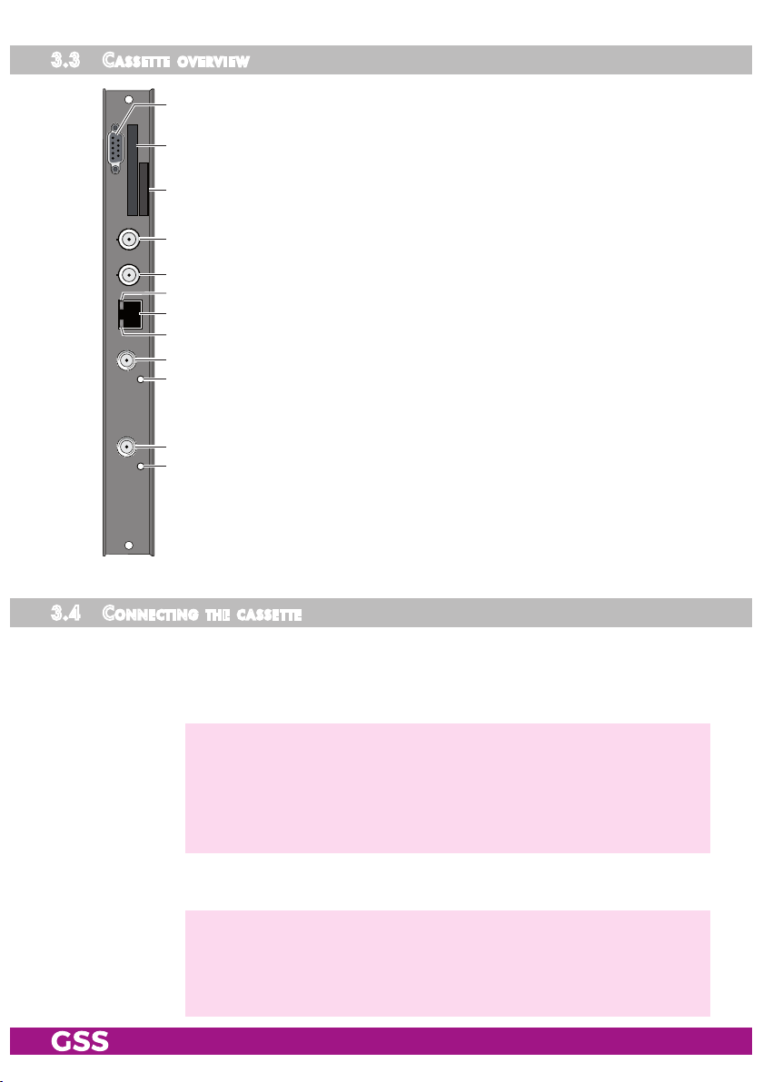
3.3 Cas sette overv iew
2 SAT IF input
3 Status LED
4 SAT IF input
1 Status LED
@
!
0
of channel strip "B"
of channel strip "B"
of channel strip "A"
of channel strip "A"
5 Status LED of the LAN interface (data transfer)
6
7 Status LED of the LAN interface (network connection)
8 not used
9 not used
0 Type label
! Slot for a CA module
9
8
7
6
5
4
3
LAN socket
@ D-SUB socket "RS 232"
2
The operating software of the cassette can be updated via the
You can find the current operating software on the website
3.4 Con neCting the C a ssette
1
9-pin D-SUB socket "RS 232" using a PC or notebook and the
software "BE-Flash".
"www.mygss.eu".
• Connect the RF connections to the inputs
2
(channel strip "
2 Fjack-to-jack adapters (cable connectors) are attached.
—> If you need the DiSEqCTM control the input signal must not be fed via
The control voltage for a DiSEqCTM controlled multi switch which is
Therefore use an external power supply.
• Connect the LAN socket 6.
—> In order to avoid restrictions of the network data rate (and therefore
—> Exclusively use "Layer 3 switches", which support the IGMP protocol.
- 10 - PHIS 1000 S
Tuner B
the input distributor.
present at the antenna input is not suitable as its power supply.
possible disturbances) we recommend to operate other applications
like e.g. Internet, VOIP telephony etc. in separated networks.
"). To connect a DiSEqCTM controlled multi switch
4 (channel strip "
Tuner A
") and

3.5 retr o fitting a Ca module
The cassette is equipped with a common interface. It allows you to connect a
CA module for various
channels can only be de
bl
ing system and the corresponding smart card. The smart card contains all
the information for authorisation, de
– Check with the distributor or manufacturer of the CA module to be used to
ensure that it is suitable for de
– The hardware and software of this cassette have been thoroughly prepared
and tested. Any changes made by service providers to the data structures in
the service data might impair or even prevent this function.
– When working with the CA module, please read the corresponding operat-
ing manual from the respective provider.
• Insert the smart card 1 into the CA module 2 so that the chip 3 on the
smart card faces the thicker side (top) of the CA module.
• Insert the CA module into the guide rails of the CA slot 4 with the top side
of the CA module facing the top side of the cassette.
• Push the CA module without canting into the guide rails of the CA slot 4
and contact it to the common interface.
scrambling
scramble
scrambl
systems and service providers.
d with a CA module suitable for the
scrambl
ing and subscription.
ing several services.
Scrambl
ed
scram-
34 12
- 11 - PHIS 1000 S

4 the Control Panel at a glanCe
4.1 menu i tems
Programme the
cassette
using the buttons on the control unit of the head-end
station. The two-line display of the control unit then shows the menus.
The parameters and functions to be set are underlined.
Use the key to select the following main menu items:
– Programme tables (optionally*)
– Setting Ethernet parameters
– Selecting the Input (optionally*)
– Assignment of the IP addresses (optionally*)
BE-Re mote V 45
PROFESSION AL
– Data Mode
– Displaying the data rate
– Factory reset
*) depending on the activation of the
virtual station tables.
4.2 Con trol Pane l
The key pad on the head-end station is used to scroll through the menus:
scrolls forward through the menus.
select parameters in the menus.
set values, initiate actions.
selects sub-menus.
scrolls backward through the menus.
saves all entries.
- 12 - PHIS 1000 S

5 Programming
5.1 overv i ew
Points 5.2/5.5 describes the programming of the cassette via the operating unit
of the head-end station.
The programming of the stations to be received can also be done via a text file
(station tables) which is uploaded to the cassettes.
funC tion "virt ual station tab les"
For special applications it is possible at a combination of cassettes
("receiving cassettes") and PSPT/Q 1000 ("transmitting cassettes")
configuration quickly via "virtual station tables".
Here, the programming of several station tables (LOCATIONS) of the receiving
cassettes as well as their assignment to the transmission channels (transponders)
of the transmitting cassettes is done by a text file which must be uploaded to the
cassettes.
The switchover of the different station tables is done via the menu "LOCATION"
in the
PHIS 1000 S cassettes. This menu only appears if station tables were up-
loaded before. The menus "INPUT" and "IP-OUT" then are hidden.
In point 5.3 the structure of a corresponding text file and in point 5.4 the pro-
gramming of the cassettes (upload) is described.
Prog ra m m i n g via statio n ta b les
• First set the "hardware" IP addresses of all cassettes
PSPT/Q 1000
• Create the text file (station tables) using a text editor.
• Upload the text file (station tables) to the corresponding cassettes.
• Finally programme the cassettes.
.
PHIS 1000 S
to change the
PHIS 1000 S and
- 13 - PHIS 1000 S
5.2
BE–Remote
please wa it …
V 45
Box 4
V 5
HOT-SP TS
0.128 – – –
Box 1
………
……
……
Bx 1A
C5-12,S3- 24
TWIN-SAT
C07
Böx 4
C5-12,S3- 24
TWIN-SAT
C07
Box 5
………
……
……
+
t > 10 s
Bx 4
stat =>
ETHERNET
Options
stat / DHCP
Bx 4
---
LOCATIO N
A
A
Bx 4
192.168. 0. 1
IP-GATEWAY
Bx 4
255.255.2 55. 0
IP-MASK
▶
◀
/
Bx 4
192.168. 0.1 28
IP-ADDR
▶
◀
/
▶
◀
/
Bx 4
60000
UDP-PORT
▶
◀
/
B
▶
0 … 65535
Ein / On
M
Bx 4
DELETE
LOCATIO N
=> M
Programmtabellen
Channel tables
nur bei Funktion "virtuelle Programmtabellen"
only with function "Virtual station tables"
nicht bei Funktion "virtuelle Programmtabellen"
not with function "Virtual station tables"
Tuner A /
Tuner B
Bx 4A
10600 MHz
LNB
off
▶
Bx 4
Tuner A OK
INPUT
=>
*DiSEqC
TM
is a trademark of EUTELSAT
DiSEqC
TM*
:
off/– –Hh …DFV1
10600 / 9750
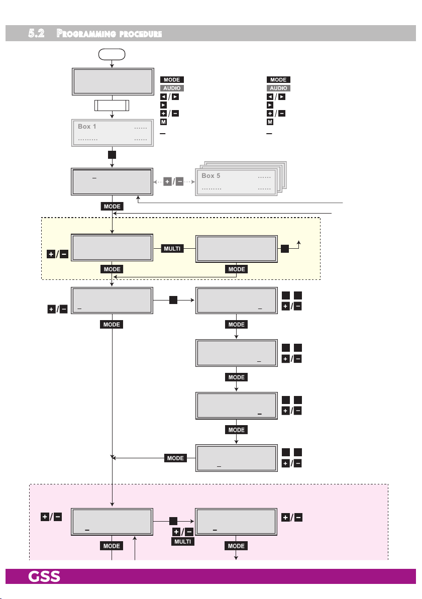
Bedienhinweise
"blättert" Menüs vorwärts.
"blättert" Menüs rückwärts.
wählen die Eingabeposition
wählt Untermenü
stellen Werte ein,.
speichert alle Eingaben.
1 zeigt die Eingabeposition
Operating Hints
scrolls forward through the menu.
scrolls backward through the menu.
select the enter position.
selects a submenu.
set values and triggers actions.
saves all entries.
1 shows the enter position
Pro g r a m m i n g Pro C e dure
Page 16
- 14 - PHIS 1000 S

Box 1
………
……
……
Bx 1A
C5-12,S3- 24
TWIN-SAT
C07
Böx 4
C5-12,S3- 24
TWIN-SAT
C07
Box 5
………
……
……
Bx 4
60000
UDP-PORT
▶
◀
/
0 … 65535
nicht bei Funktion "virtuelle Programmtabellen"
not with function "Virtual station tables"
Tuner A /
Tuner B
Bx 4A
11836 -1.8
FREQ
CN 12
Bx 4A
27500 DVB-S
SYMBOL
▶
◀
/
▶
◀
/
Bx 4A
10600 MHz
LNB
off
▶
Bx 4
Tuner A OK
INPUT
=>
Kanalzug “A” mit CA-Modul
Channel strip “A“ with CA module
*DiSEqC
TM
is a trademark of EUTELSAT
Kanalzug “A” ohne CA-Modul,
Kanalzug “B” /
Channel strip “A“
without CA module,
Channel strip “B“
DVB-S / QPSK… /
8PSK… / DTV…
▶
◀
/
DiSEqC
TM*
:
off/– –Hh …DFV1
10600 / 9750
27500 / 22000
IP-OUT 1
…
IP-OUT 12
IP 1
227. 40. 50. 1
OUT-IP
IP 1
7 off
PKTS / FE C
IP 1
off UDP
MODE / PO RT
1234
▶
Bx 4
Das Erste
IP-OUT 1
=>
on / off
UDP / RTP,
0 … 65535
copy
off / 10/9 … 20/19
Annex A / Annex B
copy1 … 7
auto
Bx 4A
Menu <=
CA
=> Edit
*) Die angezeigte Information ist
abhängig vom verwendeten
CA-Modul.
The information displayed is
dependent on the CA module
used.
Bx 4A 01/03
Informati on *)
MENU
Bx 4A TV X
. . . .
04/09
X – entschlüsseln
descrambling
0 – nicht entschlüsseln
no descrambling
X / 0
nächster Service
next service
Bx 4A
PID Check
CA
on
▶
◀
on / off
M
▶
◀
/
▶
◀
/
▶
◀
/
▶
◀
/
- 15 - PHIS 1000 S

Box 1
………
……
……
Bx 1A
C5-12,S3- 24
TWIN-SAT
C07
Böx 4
C5-12,S3- 24
TWIN-SAT
C07
Box 5
………
……
……
IP-OUT 1
…
IP-OUT 12
IP 1
227. 40. 50. 1
OUT-IP
IP 1
7 off
PKTS / FE C
IP 1
off UDP
MODE / PO RT
1234
▶
Bx 4
Das Erste
IP-OUT 1
=>
on / off
UDP / RTP,
0 … 65535
copy
off / 10/9 … 20/19
Annex A / Annex B
copy1 … 7
auto
▶
◀
/
▶
◀
/
▶
◀
/
IP 1
( 7.3) >
IP 1 TV
Das Erste
DATARATE
! 10. 0 MB
001/016
◀
▶
/
auto
2 … 80.0 MBits
constant /
unmodified
Bx 4
constant
Bx 4
0 Mbps
Bx 4
Defaults
DATAMODE
DATARATE
FACTORY
=>
IP 1
all
IP 1
auto
manual
Bx 4
ac3 txt su b eit
AUDIO
PIDS
manual
OPTIONS
all / 01/…
manual/auto
Nur wenn "PIDS" –> "manual"
Only if "PIDS" –> "manual"
AC3 / ac3, TXT / txt,
◀
▶
/
SUB / sub, EIT / eit
(ON / off)
copy
Page 14
▶
Bx 4
STORE
FACTORY
=> M
A
M
B
Page 14
- 16 - PHIS 1000 S

5.3 Cre ati ng stati on ta bles
The head-end station can be pre-programmed with different station allocations
via the station tables. Then the configuration can be switched over by the
menu "Location" of the cassette
PHIS 1000 S.
The station tables are created using a text editor and stored e.g with the title
"config.txt" in one text file (maximum file size 64kB).
The following example shows the structure of the text file:
L "Name 1"
I 227.40.50.0:1234
S 1,D1,9750,10600
S 2,D2,9750,10600
S 3,D3,10600,9750 // HI and LO interchanged at the inputs
S 4,D4,0,5150 // C band at the HI inputs
T 1,11836,H,27500 // ARD transponder
I 1,0x6DCA,0,AC3,10.2,EIT,"ARD" // ARD
I 16,0x6DCB // BR3
I 17,0x6DCC // HR3
Tuner A
Cassette 1
I 18,0x6DCF // WDR Köln
I 19,0x6DD1 // SWR
I 20,0x6DD0 // BR Alpha
T 1,10744,H,22000 // EinsExtra-Transponder
I 10,0x7031 // EinsExtra
I 11,0x7032 // EinsFestival
I 12,0x7033 // EinsPlus
Tuner B
I 22,0x7034 // Arte
Cassette 1
I 23,0x7035 // Phoenix
…
…
…
…
L "Name 2"
I 227.40.50.0:1234
T 1,12480,V,27500 // DSF-Transponder
I 48,0x0384 // DSF
Tuner A
Cassette 1
I 49,0x0033 // Tele5
I 50,0x0020 // Sonnenklar
T 1,11954,H,27500 // ZDF-Transponder
I 2,0x6D66 // ZDF
I 13,0x6D6B // ZDF-Info
I 14,0x6D6E // ZDF-Neo
I 15,0x6D70 // ZDF-Theater
Tuner B
Cassette 1
I 21,0x6D67 // 3SAT
I 27,0x6D68 // KIKA
…
…
…
I 227.40.50.0:1234
O 474,0x0001,0x0100,6900,256
MOD A
I 1,1
I
I
I
O 482,0x0002,0x0100,6900,256
I
MOD B
I
I
I
PHIS 1000 S
PHIS 1000 S
PSPT/Q 1000
Receiving table "Name 1"
Receiving table "Name 2"
Transmitting table
SAT
settings
Output IP
Service 1-6
Transponder
Output IP
Transponder
Service 7-12
Output IP
Service 1-6
Transponder
Output IP
Transponder
Service 7-12
LCN
Input IP
Cassette 1
LCN
Input IP
Cassette 1
- 17 - PHIS 1000 S

th e str u Cture o f the t e x t fil e for Pro gr a m m ing stat i o n ta b les
—> Programming for the receiving cassette
PHIS 1000 S
L "Name 1"
L Identifier for "Location"
"Name 1" arbitrary title, this title is shown in menu "Location" for select-
ing the configuration.
S 1,D1,9750,10600
S Identifier SAT
1 Index, 1 = SAT configuration S1
, Commas are the separators between the items
D1 Multi switch command
— = no DiSEqCTM/tone burst
T1 tone burst input 1
T2 tone burst input 2
D1 DiSEqCTM input 1
D2 DiSEqCTM input 2
D3 DiSEqCTM input 3
D4 DiSEqCTM input 4
9750 defines the LNB oscillator frequency of the low band input
10600 defines the LNB oscillator frequency of the high band input
—> By appropriate entries of the oscillator frequencies e.g. HI and LO
can be interchanged at the inputs. Also C-band entry is possible. If
an input is not used "0" must be entered for the oscillator frequency.
Example: "S 4,D4,0,5150" —> LO input not used,
C-band at the HI input
I 227.40.50.0:1234
I Identifier for IP address (range)
227.40.50.0 IP address range e.g. 227.40.50.0-255
the IP address must be within the "multicast" range from
224.0.0.0 to 239.255.255.255.
:1234 Port
—> This sequence must be entered behind the "Location" sequence of
every receiving table and before the transmitting table.
- 18 - PHIS 1000 S

T 1,11836,H,27500 // ARD transponder
T Identifier for transponder
1 Selection of the "SAT configuration" (S 1,D1,9750,10600)
, Commas are the separators between the items
11836 Downlink frequency
H Polarity - H, L
27500 Symbol rate
// ARD… Comment; following the "double slash" comments can be en-
tered.
—> With this sequence the LNB settings of one tuner of one cassette are
predefined. The order of the cassettes is defined by the order of the
hardware IP addresses which are assigned to the cassettes manu-
ally (page 25).
Tuner A receiving cassette 1, tuner B receiving cassette 1, tuner A
receiving cassette 2, tuner B receiving cassette 2, etc.
—> A DiSEqC controlled multi switch can be controlled by "SAT configu-
ration" and "Polarity". The control voltage which is present at the
antenna input is not suitable as power supply of the switch.
Use an external power supply.
I 1,0x6DCA,0,AC3,EIT,10.2,"ARD" // ARD
I Identifier for IP address
1 Output IP address (fourth number) e.g. 227.40.50.1
, Commas are the separators between the items
0x6DCA Service ID (SID); can be entered in hexadecimal or deci-
mal (28106) value. —> You can find the SIDs of the stations
whished e.g. in the internet.
0 Audio PID, 0=all, 1=1st audio,…
AC3 AC3 flag
EIT EIT flag
10.2 fixed data rate in MB
"ARD" Individual station name
—> The order of the first three settings is mandatory
IP-Adresse , Service-ID , Audio-PID ,
from the example: I 1 , 0x6DCA , 0 ,
From the fourth setting on (behind the 3rd comma) the order is flex-
ible!
—> AC3 and EIT are so called "Flags" (software switches), which set
certain PIDs.
- 19 - PHIS 1000 S

Possible Flags are:
AC3 —> AC3 tone
NOAC3 —> No AC3 tone
TXT —> Teletext
SUB —> DVB subtitle
EIT —> Event Information Table, included information about
the service (e.g. start time, duration, scrambling etc.).
NONE —> suppresses other PIDs
ALL —> passes through all PIDs
CA —> Service shall be descrambled.
"text" —> individual station name
—> If no flags are set, all PIDs and EIT are passed through.
—> With the following sequence, for example, the same flags for all
services of the hole table can be set:
F TXT,AC3
F —> Identifier for flag setting
TXT —> Teletext
, Commas are the separators between the items
AC3 —> AC3 tone
—> These flags are set for all services after this sequence, for which
flags are not set individually, - until other flags are set with a new
flag setting sequence.
Programming for the transmitting cassettes
O 474,0x0001,0x0100 (
PSPT 1000
O 474,0x0001,0x0100,6900,256 (
PSPT/Q 1000
)
PSPQ 1000
)
O Identifier for output settings.
474 Output frequency (e.g. 474.00 MHz).
, Commas are the separators between the items
0x0001 Transport stream ID
0x0100 ORGNET-ID
6900 Symbol rate 1000…7500 (
256 QAM modulation 64/256 (
- 20 - PHIS 1000 S
PSPQ 1000
PSPQ 1000
)
)

—> With this sequence the settings of one modulator of one cassette
are predefined. The order of the cassettes is defined by the order
of the hardware IP addresses which are assigned to the cassettes
manually. Modulator A transmitting cassette 1, modulator B transmitting
cassette 1, modulator A transmitting cassette 2, modulator B transmitting
cassette 2, etc.
I 1,2
I Identifier for IP address
1 Input IP address (fourth number) e.g. 227.40.50.1
, Commas are the separators between the items
2 LCN; Logical Channel Number
—> Because of a more easily explanation the digits 1 and 2 are used in
this example. In order to retain an overview, we recommend to use
the same digit for the IP address as well as the station number (e.g.
I 1,1).
- 21 - PHIS 1000 S

5.4 uPl oading the s tat ion tables to t h e Cass e t tes
To upload the station tables to the cassettes the software "HotelTransponder.
exe" is needed. It can be downloaded from:
http://212.20.172.90/Kopfstation/CD/Software/Hotel/HotelTransponder.exe
—> Your PC must be connected to the cassettes via LAN (within the same
IP address range as used for connecting the cassettes, page 25).
• Store the text file, for example, under the name "config.txt".
• Start the software "HotelTransponder.exe" by using the following string in
the command line:
HotelTransponder.exe config.txt 1 60000 –O
HotelTransponder.exe starts the software
config.txt selects the text file
1 sets the default receiving table (for example table
1; the first table in the text file).
60000 sets the port. This port must be identical with the
port set in the UDP port setting (page 27).
–O textfile is also uploaded to the transmitter cas-
settes. If the text file shall be uploaded only to the
receiver cassettes, "-O" must not be used in the
string.
—> The software starts and loads the station tables included in the text
file to the corresponding cassettes.
—> The order of the cassettes is defined by the order of the hardware IP
addresses which are assigned to the cassettes manually.
- 22 - PHIS 1000 S

5.5 Pro g r a m m i n g the Cass et te
Box 1
………
……
……
Bx 1A
C5-12,S3-24
TWIN-SAT
C07
Böx 4
C5-12,S3-24
TWIN-SAT
C07
Box 5
………
……
……
—> Pressing the button for longer than 2 seconds cancels the
programming procedure. This takes you back to the program item
"Selecting the cassette" from any menu. Any entries that have not
been saved are reset to the previous settings.
—> Entries in the menus can be saved by pressing the key. You are
taken back to the "Selecting the cassette" menu item.
—>
Pressing the
button returns to the previous menus.
• Switch on the head-end station
—> The display shows the software version (e.g. V 45)
—> The processor reads the
Ein / On
cassettes
‘ data (approx. 10 seconds).
seleC ting t he Cas s et te
+
Box 4
V 5
• Select the
cassette
HOT-SP TS
0.128– – –
you want to program (e.g. Box 4) by repeatedly pressing
the button if necessary.
—>
The display shows e.g. the menu"Box 4 HOT-SPTS":
"Box 4" stands for
"HOT-SPTS" type of cassette
"V 5" software version of the cassette
192.168."0.128" hardware IP address of the cassette
BE–Remote
please wa it …
t > 10 s
V 45
slot
4,
- 23 - PHIS 1000 S

• Press the button.
—> The "Selecting the station table"
– "LOCATION" ("virtual station ta-
bles" is activated) or "Setting the Ethernet parameters" – "ETHERNET"
("virtual station tables" is not activated) menu is activated.
seleC ting t he st at ion table
In this menu you select the receiving station table (LOCATION) from the text file
e.g. "config.txt" to be used.
Bx 4
---
—> Instead of "---" the name of the table "Name 1" of the 1st receiving
table from the text file is shown
LOCATION
.
• Use the buttons to select the receiving table wished.
• Press the button.
—> The "Setting the Ethernet parameters" – "ETHERNET" menu is acti-
vated.
setting the ethernet Pa r am eters
In this menu you specify whether the Ethernet parameters for the cassette are
entered automatically by a connected server ("DHCP"), or whether you want
to enter them manually ("stat"). To assign the cassette uniquely, each IPTV cassette must be allocated its own IP address.
Bx 4
stat =>
ETHE RNET
Opti ons
• Press the buttons to select manual setting ("stat") or automatic setting
("DHCP") of the Ethernet parameters.
- 24 - PHIS 1000 S
• Press the
button to activate the setting options
("Options")
.
—> The "Setting the hardware IP address of the cassette"
"IP-ADDR" is activated.
– menu
set ting th e hard war e iP a d dress o f th e Cass ette
—> Two IP address ranges are used:
– "Hardware" IP addresses (menu ETHERNET), which are used to con-
nect the cassettes in the network (e.g. 192.168.0.x).
– "IPTV" IP addresses (menu IP-OUT), which are used to send and re-
ceive the IPTV channels (e.g. 227.40.50.x). These IP addresses must
be within the "multicast" range from 224.5.0.0 to 231.255.255.255.
To operate the cassette in a network, an IP address must be assigned to
each IPTV cassette. If a manually setting of the Ethernet parameters is selected, set the IP address of the cassette in this menu. If "DHCP" is selected,
the "IP-ADDR", "IP-MASK" and "IP-GATEWAY" sub-menus display the param-
eters that were assigned automatically by a connected DHCP server, e.g.
"192.168. 0.128*". The star " * " in the display means that the data is
provided by a DHCP server. If no server is connected, " 0. 0. 0. 0"
appears in the corresponding menu.
Bx 4
192. 168. 0.128
IP-A DDR
• Use the
buttons to place the cursor under the digit of the IP address
displayed to be set and use to set the IP address wished.
• Press the
—> The "Setting the address range"
- 25 - PHIS 1000 S
button.
– "IP-MASK" menu is activated.
setting the a d d ress r ange
In this menu you define the address range for the cassettes connected to the
LAN network.
• Use the
Bx 4
255. 255.255. 0
buttons to place the cursor under the digit of the IP address
IP-M ASK
displayed to be set and use to set the IP address wished.
• Press the
—> The "Setting the address of the gateway"
button.
– "IP-GATEWAY" menu is
activated.
setting the a d d ress of th e gateway
The address of a gateway (server/router) can be set in this menu. If no gate-
way is used you can skip this setting.
• Use the
Bx 4
192. 168. 0. 1
buttons to place the cursor under the digit of the IP address
IP-G ATEWAY
displayed to be set and use to set the IP address wished.
• Press the
—> The "Setting the UDP port"
- 26 - PHIS 1000 S
button.
– "UDP-PORT" menu is activated.
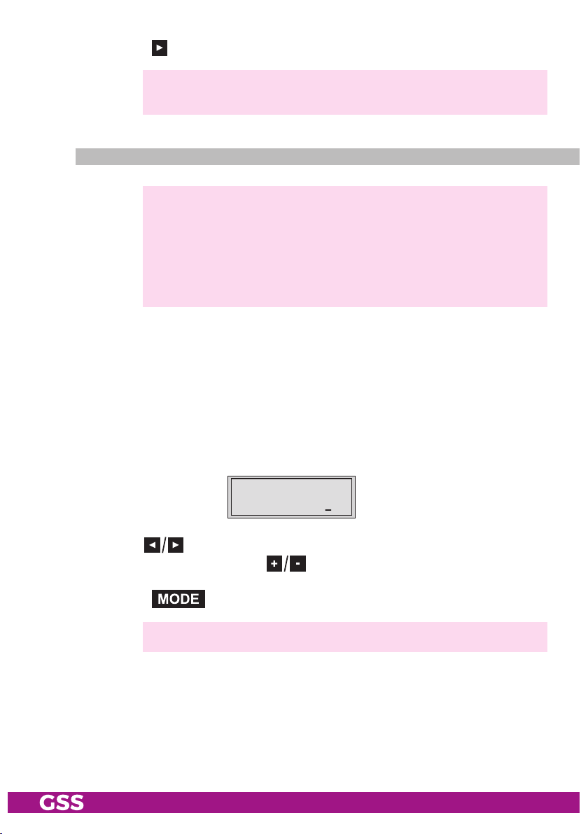
setti ng the udP P o rt
The UDP port setting is required if the text file with the station tables can not
be uploaded via port 60000 (default). The port set must match to the port for
uploading the text file (page 18).
• Use the
Bx 4
6000 0
buttons to place the cursor under the digit of the port number
UDP- PORT
displayed to be set and use to set the port number wished ("0" …
"65535").
• Press the button.
—> The menu
–
"Stuffing the data rate" – "DATAMODE" ("virtual station tables" is
activated, continue on page 40) or
– "Selecting the input data stream" – "INPUT" ("virtual station tables"
is not activated) is activated.
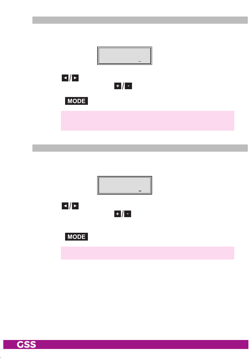
seleC ting t he inPu t data stre am
In this menu you select the signal source for the selection of the services. The
data streams to be processed are provided by "Tuner A" and "Tuner B".
Bx 4
Tuner A OK
INPU T
=>
• Press the buttons to select the signal source of the input data stream
("Tuner A", "Tuner B").
—> "OK" indicates that a transponder is received. If there is no input
signal available "––" is displayed instead of "OK".
—> Press the button to skip the settings of the input param-
eters. The "Setting the output parameters" – "IP-OUT 1" menu is
activated (page 32).
• Press the button.
- 27 - PHIS 1000 S

—> The "Setting the LNB oscillator frequency" – "
LNB
" menu is acti-
vated.
lnb o sCillat o r fr equenCy / Co ntro l vo ltage
In this menu set the oscillator frequency of the LNB used and, if necessary, a
LNB control voltage.
Bx 4 A
1060 0 MHz
LNB
off
lnb o sCillat o r fr equenCy
• Use to position the cursor under the digit to be set for the frequency
display.
• Press to enter the oscillator frequency of the LNB used.
diseq Ctm Co m m a n ds
• In order to set a DiSEqCTM command, position the cursor under "off" using
button .
• Using buttons select the desired control voltage.
"abcd" are place-holders for the following setting options:
Bx 4A
10600 MHz
Place-holder Value Description
a _ No function
T Sound
D DiSEqC
b _ No function
A, B Sound A or B
0…F Hexadecimal value for DiSEqCTM command
0…15
c: H Horizontal polarisation
V Vertical polarisation
d: h High-Band
l Low-Band
LNB
abcd
TM
Example: DAHh means DiSEqCTM position 10, Horizontal high
- 28 - PHIS 1000 S
—> The control voltage only serves to control multiswitches and is not
suitable for power supply of upstreamed components (maximum
load 65mA).
—> GSS Multiswitches must be triggered by the following DiSEqCTM
comands:
Input group A —> DiSEqCTM command D0
Input group B —> DiSEqCTM command D1
Input group C —> DiSEqCTM command D2
Input group D —> DiSEqCTM command D3
Example: In order to trigger input group B for horizontal polarisa-
tion and high band D1Hh must be set.
• Press the button.
—> The "Setting the input symbol rate, setting the DVB mode" –
"SYMBOL" menu is activated.
setting the i nPut s ymbo l rat e
The symbol rates of the satellite transponders can be found in the current chan-
nel table of the satellite operator, in various satellite magazines and in the
Internet.
Bx 4 A
2750 0 DVB-S
SYMB OL
• Using the button the symbol rates 27500" or "22000" can be
selected directly.
• To set other symbol rates use the buttons to position the cursor under
the digit of the symbol rate displayed to be set.
• Press
to enter the respective digit of the symbol rate needed.
• Repeat the procedure by the quantity of the digits to be set.
- 29 - PHIS 1000 S

setting the dvb m o d e
The cassette recognizes the transmitted DVB mode and switches over between
the normal QPSK mode (DVB-S) and the DVB-S2 mode. Receiving stations
with DVB-S2 mode, we suggest to preset the DVB mode to shorten the time for
searching stations.
Bx 4 A
2750 0 DVB-S
SYMB OL
• Use the button to place the cursor under "DVB-S" and set the required
DVB-S2-mode with the
buttons.
• Press the button.
—> The "Setting the input frequency" – "FREQ" menu is activated.
setting the i nPut f requenC y
If three dots " … " appear in the second line of the display, the cassette is in
the "station search" mode. Please wait until the process has finished.
Once the RF receiver has synchronised to the input signal, any offset to the
target frequency is displayed in MHz, e.g. "– 1.8".
If a question mark "?" appears in the second line of the display, there is no
input signal present. Check the configuration of the antenna system and headend station as well as the preceding settings of the cassette.
Bx 4 A
11836 -1.8
FREQ
CN 1 2
• Use the buttons to position the cursor under the digit of the frequency
displayed to be set.
• Press
• Set the frequency offset shown in the display
1MHz
- 30 - PHIS 1000 S
to set the input frequency.
by varying the input frequency
(e.g. "– 1.8")
using the
to less than
buttons.

—> The "CN 12" display indicates the signal to noise ratio of the signal
received.
—> The quality of the received transport stream (level and C/N) is indi-
cated by a status LED.
—> If the LED lights yellow the SAT IF input level and the signal to noise
ratio must be tested.
Status LED
"TUNER A"
Status LED
"TUNER B"
LED indicator Indication
Green Signal quality is good
Yellow
Signal quality is insufficient
Red No signal
• Press the button.
Selection Tuner A and CA module installed:
—
> The
"Setting the PID monitoring" – "CA_PID-Check" menu is acti-
vated (page 42).
Selection Tuner B or Tuner A without CA module:
—
> Return to the "Selecting the input data stream"
– "INPUT" menu
(page27).
—> If necessary set
the input parameters of the further input signal sourc-
es.
• Press the button.
—> The "Setting the output parameters" – "IP-OUT 1" menu is activated.
- 31 - PHIS 1000 S

setting the o u tPut Paramet ers
In this menu you select the IP output, for which you would like to set the output
parameters in the submenus.
• Press the
"
IP-OUT 12
—> In the second line of the display the service is indicated allocated
—> To skip the settings of the output parameters press the
buttons to select the IP output to be set ("
").
to the IP output (e.g. "Das Erste"). If "off" is shown, the output is
deactivated.
button. The "Stuffing the output data rate" – "DATAMODE" menu is
activated.
• Press the button.
—> The "Setting the IP addresses for the services" – "OUT-IP" menu is
activated.
Bx 4
off
IP-O UT 1
=>
IP-OUT 1
" …
- 32 - PHIS 1000 S

setting the iP addre s ses f o r the o utPut s
In this menu you set the IP address for the IP output selected.
—> "IPTV" IP addresses (menu IP-OUT), which are used to send and re-
ceive the IPTV channels (e.g. 227.40.50.x) must be within the "multicast" range from 224.5.0.0 to 231.255.255.255.
The software allows to allocate the IP addresses to the further outputs automati-
cally in ascending order.
IP 1
227. 40. 50. 1
OUT-IP
If an already used IP address (in the cassette) is selected, an exclamation mark
" ! " appears in the first line of the display beside the number of the IP output.
IP 1 !
227. 40. 50. 1
OUT-IP
Allocating IP addresses to the outputs manually
• Press the buttons to position the cursor under the digit of the IP address to be set.
• Using the buttons set the IP address wished
.
Allocating IP addresses to the outputs automatically
• Pressing the button the following outputs are allocated with IP addresses in ascending order, starting from the IP address set.
—> The display shows "
auto
" for a short time.
• Press the button.
—> The "Switching the IP address off or on, selecting the transmission
protocol, setting the port number" – "
vated.
MODE / PORT
" menu is acti-
- 33 - PHIS 1000 S

swit C hing th e iP a d dress off o r on
seleC ting t he tr an smiss ion Pr o toCo l
setting the P o rt num ber
In this menu you can switch off the IP address displayed, and define the trans-
mission protocol and the port number.
IP 1
MODE / PORT
Switching the IP address off or on
• Press the
off UDP
buttons to switch off ("
12 34
off") or ("on
") the IP address and the
service referred.
Bx 4
off
IP-O UT 1
=>
Selecting the transmission protocol
• Press the button to position the cursor under "UDP".
• Using the buttons to select the transmission protocol wished:
"UDP" – The User Datagram Protocol is for the connectionless transmission of
data without acknowledgement from the receiver.
"RTP" – The Real-time Transport Protocol additional transmits time informa-
tions for runtime error correction at receiver side.
Setting the port number
• Press the button to position the cursor under the port number e.g.
" 1234".
• Use the buttons to position the cursor under the digit of the port
number displayed to be set.
• Using the buttons set the port number wished.
Copying the settings to all IP outputs
• Pressing the button the settings can be copied to the IP autputs
following from the selected on.
—> The display shows "
copy
" for a short time.
- 34 - PHIS 1000 S

• Press the button.
—> The "Defining the quantity of data packets, setting the forward error
correction, setting the transmission channel" – "PKTS / FEC" menu is
activated.
definin g the q uanti t y of data PaCke ts
setting the f o rwa rd err o r Corr e Ction
setting the t r a nsmiss ion Cha n n e l
In this menu you set the quantity of the data packets to be transmitted, the
forward error correction FEC and the transmission channel. If the forward error correction is used additional redundant data are transmitted, so that the
addressee can correct transmission errors.
IP 1
7 off
PKTS / FEC
Defining the quantity of data packets
• Using the buttons define the quantity of MPEG data packets in one IP
data packet ("1" … "7").
—> Setting "7" results the smallest overhead.
Setting the forward error correction
• Press the button to position the cursor under "off" .
—> In position "off" the forward error correction (FEC) is switched off.
• Using the buttons set the value of the FEC wished ("off, 10/9" …
"20/19").
IP 1
7 10/09 Anne xB
PKTS / FEC
Setting the transmission channel
• Press the button to position the cursor under "Annex…".
• Use the buttons to set the transmission channel wished ("AnnexA" /
"AnnexB").
- 35 - PHIS 1000 S

Copying the settings to all IP outputs
• Pressing the button the settings "Quantity of the data packets",
Forward error correction" and "Transmission channel" can be copied to all
IP outputs.
—> The display shows "
copy
" for a short time.
• Press the button.
—> The "Setting the output data rate" – "DATARATE" menu is activated.
setting the o u tPut data rate
In this menu you can set the output data rate of each IP output optionally to
automatic (auto) or to a fixed value.
IP 1
( 7.3) >
—> The sum of the output data rates of all IP outputs must not exceed 80
Mbps (100-BASE-T interface).
DATARATE
! 10.0 MB
The current needed data rate is shown on the left side in parentheses (e.g.
7.3 MBits). This indication is dropped at setting "auto".
• Use the buttons to position the cursor under the digit of the data rate
displayed to be set.
• Using the buttons set the desired data rate.
—> Indication ">": Current needed data rate of this IP output is higher
than the data rate set (overflow).
Indication "!": The sum of all output data rates set is higher than
80 MBits.
• Press the button.
—> The "Allocating services manually" menu is activated.
- 36 - PHIS 1000 S

allo Cati ng serv i Ces m anual ly
In this menu all services (programmes) supplied via "TunerA" and "Tuner B"
can be displayed and each service is assigned a set IP address in the "OUT-IP"
menu. The service can be accessed in the connected network using the given
IP addresses for this output in the "OUT-IP" menu.
IP 1 TV
Das Erste
001/ 016
• Using the buttons select the service wished
—> The display shows e.g.:
Das Erste
Meaning of the indicators in the example:
"IP 1" IP address with the consecutive number "1"
"TV" Type of service "Television"
"0
01/016" The 1st of 16 services is being allocated to the IP ad-
dress.
"
Das Erste
" Name of the service
Further possible terms displayed:
"RA" Type of the service "Radio"
For radio stations, the back
connected TV or test receiver is darkened.
"HD" HD reception.
" * " The star means that the TV or radio station selected
is scrambled. To enable the stations, the CA module
and the appropriate smart card of the station pro-
vider are required.
IP 1 TV 001/016
.
ground of the screen of the
—> If a service number (e.g. "131") appears instead of "TV" or "RA",
this indicates that an unnamed station or an undefined data stream
is being received.
If the service selected is already allocated to an IP output, in the first line of the
display an exclamation mark " ! " appears beside the type of the service.
IP 1 TV !
Das Erste
- 37 - PHIS 1000 S
001/ 016

If no service is found the display shows "–––" instead of the name of the
service. In this case check the configuration of the antenna system including
the head-end station and the previous settings of the cassette.
• Press the button.
—> The "Selecting the sound options of the service" – "AUDIO" menu is
activated.
seleC ting t he so un d oPti ons of the s e rviCe
If several sound options in different languages are transmitted in a service, you
can select the desired audio stream from the transport stream in this menu.
•
IP 1
all
Press to select the desired sound option (e.g. "all", "deu" – German, etc.).
AUDI O
• Press the button.
—> The "Automatic/Manual PIDs" – "PIDS" menu is activated.
auto m atiC/manua l Pids
In this menu you can deactivate the following menu "OPTIONS" for individual
DVB service information settings and alternately pass through all PIDs automatically.
• Press
IP 1
manual
to deactivate (auto) resp. to activate (manuals) the "OPTIONS"
PIDS
menu.
• Press the button.
—> Setting "manual"
The "Switching DVB service information on or off" – "OPTIONS"
menu is activated.
- 38 - PHIS 1000 S
Setting "auto"
Return to the "Setting the output parameters" – "IP-OUT 1" menu
(page 32).
swit C hing dvb se rviCe i n format i o n on o r off
—> This menu is only active, if in menu "PIDS" "manual" is selected.
In this menu the transmission of the DVB services (AC3 – AC3 sound, TXT
– Teletext, SUB – subtitle, EIT – Event Information Table) can be activated or
deactivated.
Bx 4
ac3 txt sub ei t
OPTI ONS
• Use the buttons to position the cursor under the transmission option
to be activated or deactivated.
• Using the buttons activate
vate
("
ac3
", "
txt
", "
sub
", "
—> Activated options are shown with capital letters, deactivated with
small letters.
("
AC3
", "
TXT
", "
SUB
", "
EIT") or deacti-
eit") the transmission option wished.
Copying the settings to all IP outputs
• Pressing the button the settings can be copied to all IP outputs.
—> The display shows "
copy
" for a short time.
• Press the button.
—> The "Setting the output parameters" – "IP-OUT 1" menu is activated
(page 32).
• Repeat the settings until all outputs are set.
• Press the button.
—> The "Stuffing the output data rate" – "DATAMODE" menu is activated.
- 39 - PHIS 1000 S

stu ffing t h e out Put data rat e
In this menu it is to set, whether the current output data rate remains "unmodi-
fied" or whether it is stuffed to a "constant" value. This value is a little bit
higher than the current "maximum" output data rate and will be customized is
necessary.
Bx 4
cons tant
DATAMODE
• Using the buttons select the data mode whished.
• Press the button.
—> The "Displaying the output data rate" – "DATARATE" menu is activated.
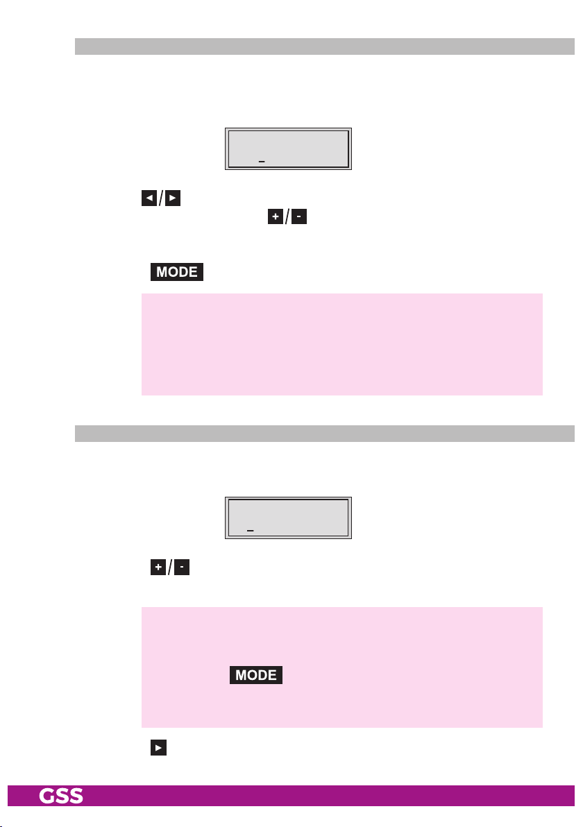
disPl ayin g the o u tPut data r ate
In this menu the current data rate is displayed.
Bx 4
72.9 56 Mbps
DATARATE
• Press the button.
—> The "Factory reset" – "FACTORY Defaults" menu is activated.
- 40 - PHIS 1000 S

faCto ry r e set
In this menu you can reset all settings to the factory defaults.
Bx 4
Defa ults
FACTORY
• Press the button.
—> The submenu "FACTORY STORE" is invoked
—> By pressing the button, you will be returned to the menu
item
"Selecting the station table"
bles" is activated) or "Setting the Ethernet parameters" – "ETHERNET"
("virtual station tables" is not activated) without
tory defaults
• Press the button.
—> The factory defaults are saved
—> Back to "Selecting the cassette" (page 23).
—> By pressing the button, you will be returned to the menu
item
"Selecting the station table"
bles" is activated) or "Setting the Ethernet parameters" – "ETHERNET"
("virtual station tables" is not activated) without
defaults
▶
=>
(page 24).
(page 24).
Bx 4
STORE
FACTORY
=> M
.
– "LOCATION" ("virtual station ta-
. The display shows "STORE"
– "LOCATION" ("virtual station ta-
M
invoking the fac-
saving the factory
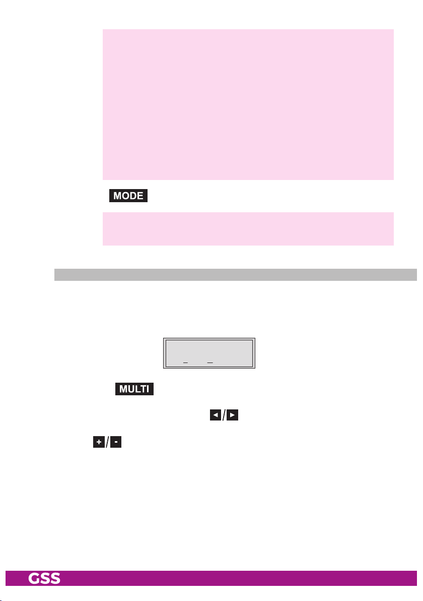
saving s e t tings
• Press the button.
—> Back to "Selecting the cassette" (page 23).
—> The settings are saved.
- 41 - PHIS 1000 S

oPerat i on wit h a Ca module
Bx4
X
.
04/09
Scrambl
the
tains all the information for authorisation, de
ed channels can only be de
scrambl
ing system and the corresponding smart card. The smart card con-
scramble
d with a CA module suitable for
scrambl
ing and subscription.
setting the Pid mo nitori ng
The factory default of the PID monitoring is switched on.
If particular PIDs are not descrambled the CA module is reset. If disturbances
occur (CA module is reset continually), the PID monitoring can be switched off.
Bx 4 A
PID Check
CA
on
• Use the buttons to switch "off" or "on" the PID monitoring.
• Press the button.
—>
The "Configuring the CA module" – "CA" menu is activated.
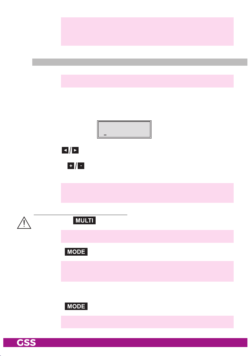
Confi guring t h e Ca m o dule
The menu varies according to which CA module you are using. For this rea-
son, please refer to the operating manual of your particular CA module. The
relevant information is shown in the display of the head-end station.
M
Bx 4A 01/03
Information *)
MENU
Bx 4A
Menu <=
Ï
CA
=> Edit
Å
Bx 4A TV X
A TV
. . . .
. . .
04/09
—> By pressing the button you can skip the "Configuring the
CA module" – "CA" menu and activate the "Selecting the input data
stream" – "INPUT" menu (page 27).
- 42 - PHIS 1000 S

• Press the
button to activate the menu of the CA module.
—> The display shows e.g.: Bx 4A 01/03 MENU
Information
Meaning of the indicators:
"
01/03
" – The first of three menu items is activated.
"
MENU
" – The menu of the CA module is activated.
For the explanation of further details please use the operating instructions
of the CA module used.
• Use the buttons to activate the submenu desired.
• Press the button to activate the submenu.
• To set the CA module use the and buttons.
• Press the button to leave the submenu.
• Press the
button to return to the "Configuring the CA module" –
"CA" menu.
• Press the button.
—> The "Descrambling services" – "Edit" menu is activated.
- 43 - PHIS 1000 S

desCr am bling s e rviCes
0
/03
)
In this menu you select the services wished from the scrambled data stream,
which are to be descrambled.
—> The display shows e.g.:
Bx 4A TV X 04/09
. . . .
Bx 4A
M
Bx 4A 01/03
x 4A
Information *)
Information *
MENU
Menu <=
Ï
=> Edit
Meaning of the indicators in the example:
"Bx 4A" Slot 4, channel strip "Tuner A"
"TV" "Television" (type of service)
"X"
"
04/09" The 4th of 9 services read is being displayed.
"
. . . .
" Name of the service
The currently
Further possible terms displayed:
"RA" "Radio" (type of service)
"HD" HD reception.
"0"
The currently selected service
CA
Å
selected
Bx 4A TV X
. . . .
04/09
service will be descrambled.
remains unchanged.
• Use the
are to be descrambled, then use
buttons to call up the services in sequential order which
to descramble ("X") or to remain
unchanged ("0").
- 44 - PHIS 1000 S

Save changes and activate the filter:
• Press the button.
—> The filter is activated. The display shows the "Configuring the CA
module" – "CA" menu.
Bx 4 A
Menu <=
CA
=> E dit
• Press the button.
—> The "Selecting the input data stream" – "INPUT" menu is activated
(page 27).
6 fi n a l ProCedures
After installing the head-end station, upgrading accessories or installing cas-
settes it is necessary to tighten all cable connections, cable terminals and cover
screws in order to maintain compliance with current EMC regulations securely.
• Securely tighten the cable bolted connections using an appropriate openended spanner.
• Mount the front cover (see assembly instructions of the head-end station).
- 45 - PHIS 1000 S
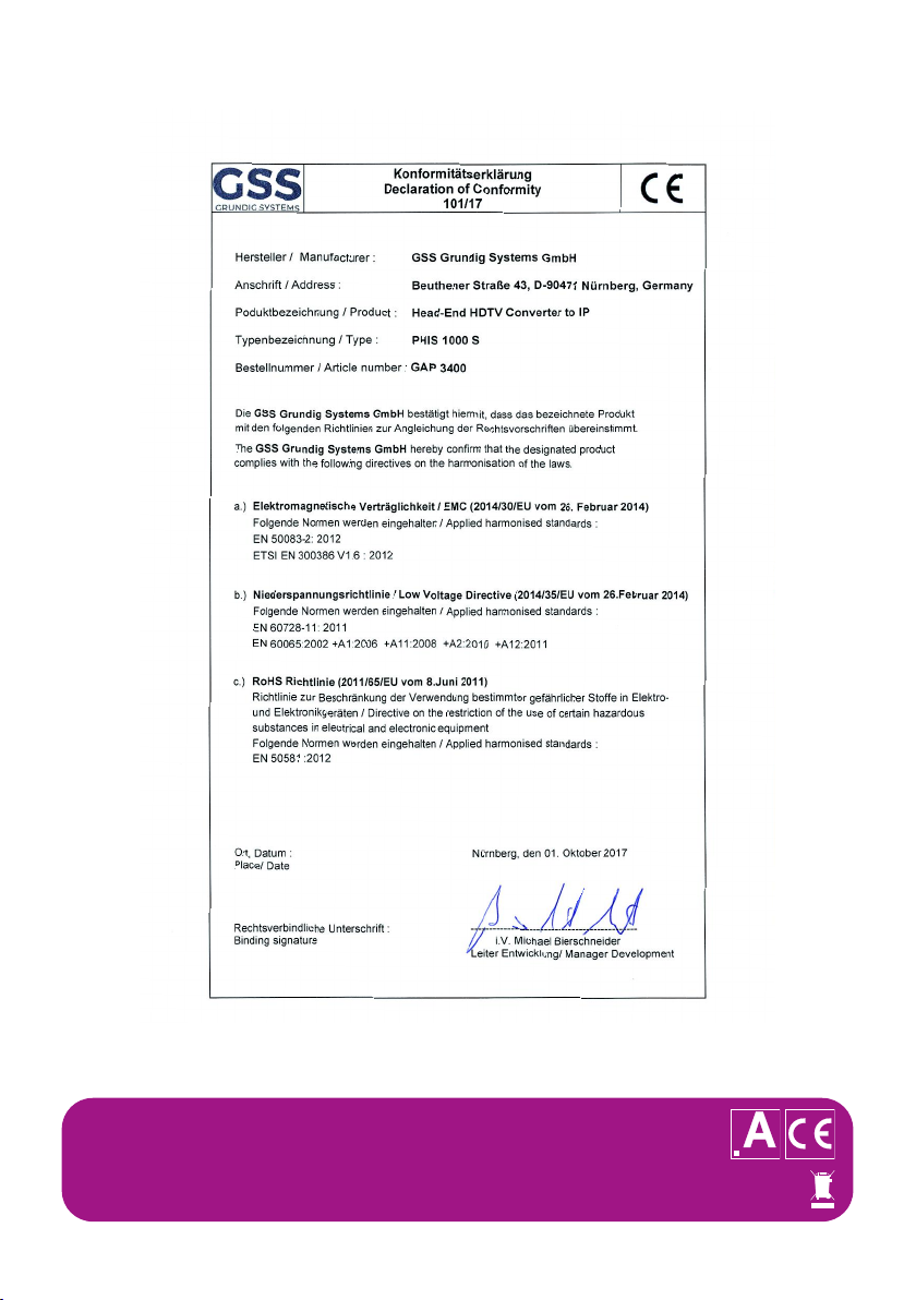
Declaration of CE conformity
GSS Grundig Systems GmbH • Beuthener Straße 43 • D-90471 Nuremberg
Phone: +49 (0) 911 / 703 8877 • Fax: +49 (0) 911 / 703 9210
www.gss.de/en • info@gss.de
KLASSEKLASSE
CLASSCLASS
Service: Phone: +49 (0) 911/703 2221; Fax: +49 (0) 911/703 2326; service@gss.de
Alterations reserved. Technical data E. & O.E. © by GSS Grundig Systems GmbH V5/001/2017
 Loading...