

Page 1
PADT 6400
Assembly Instruction
Page 2

Contents
1 Safety regulations and notes ........................................................................4
2 General information ....................................................................................5
2.1 Packing contents ............................................................................5
2.2 Meaning of the symbols used ..........................................................5
2.3 Technical data ...............................................................................5
2.4 Description ...................................................................................6
Block diagram ...............................................................................7
General ........................................................................................7
2.5 Software query..............................................................................8
2.6 How the TPS module works .............................................................9
Station filter ..................................................................................9
Changing the Transport stream and ORGNET-ID................................9
Changing the NIT ..........................................................................9
3 Assembly ..................................................................................................10
3.1 Installing the cassette....................................................................10
3.2 EMC regulations ..........................................................................11
3.3 Cassette overview........................................................................12
3.4 Connecting the cassette ................................................................12
3.5 Retrofitting a CA module ..............................................................13
4 The control panel at a glance ..................................................................... 14
4.1 Menu items .................................................................................14
4.2 Control panel ..............................................................................14
5 Programming ............................................................................................ 15
5.1 Preparation .................................................................................15
5.2
Notes on Programming ................................................................15
Level setting ................................................................................15
Generating the NIT via the control unit ...........................................15
5.3 Programming procedure ...............................................................16
5.4 Programming the cassette ............................................................19
Selecting the cassette ...................................................................19
Output settings ............................................................................20
Modulator on/off, Level...........................................................20
Channel / Frequency ..............................................................21
COFDM parameters ...............................................................23
Output signal
Transmission parameters .........................................................27
Transmitter identification ..........................................................28
- 2 - PADT 6400
...........................................................................26
Page 3

Substitute signal in the case of an incorrect input signal ...............29
ASI input ....................................................................................29
Input settings ...............................................................................30
LNB oscillator frequency, Input .................................................31
Input symbol rate, DVB mode ...................................................31
Input frequency ......................................................................32
Operation with a CA module ...................................................33
Station filter – Selection ...........................................................33
Station filter on/off .................................................................35
PID monitoring .......................................................................36
CA module ............................................................................37
Economize descrambling capacity ............................................38
Option settings ............................................................................39
Transport stream ID and ORGNET-ID .........................................39
BAT/SDT-OTHER tables ...........................................................40
Deleting a PID ........................................................................41
Renaming a PID .....................................................................41
Output data rate ..........................................................................42
Network Information Table (NIT) ....................................................42
Factory reset ...............................................................................44
Saving settings ............................................................................44
6 Final procedures ........................................................................................ 45
7 Channel and frequency tables ....................................................................46
- 3 - PADT 6400
Page 4

1 safety regulations and notes
• Assembly, installation and servicing should be carried out by authorised
electricians.
• Switch off the operating voltage of the system before beginning with assembly or service work or pull out the mains plug.
• Do not perform installation and service work during thunderstorms.
• Install the system so it will not be able to vibrate…
- in a dust-free, dry environment
- in such a manner that it is protected from moisture, fumes, splashing wa-
ter and dampness
- somewhere protected from direct sunlight
- not within the immediate vicinity of heat sources
- in an ambient temperature of 0 °C to +50 °C. In case of the formation of
condensation wait until the system is completely dried.
• Ensure that the head-end station is adequately ventilated. Do not cover the
ventilation slots.
• Beware of short circuits
• No liability is accepted for any damage caused by faulty connections or
inappropriate handling.
• Observe the relevant standards, regulations and guidelines on the installation and operation of antenna systems.
• The standards EN/DIN EN 50083 resp. IEC/EN/DIN EN 60728 must be
observed.
• For further information please read the assembly instructions for the headend station used.
• Test the software versions of the head-end station and the cassette and
update them if necessary. The current software versions can be found at
"www.mygss.eu/en".
Take action to prevent static discharge when working on the device!
Electronic devices should never be disposed of in the household rubbish. In
accordance with directive 2002/96/EC of the European Parliament and the
European Council from January 27, 2003 which addresses old electronic and
electrical devices, such devices must be disposed of at a designated collection
facility. At the end of its service life, please take your device to one of these
public collection facilities for proper disposal.
- 4 - PADT 6400
Page 5
2 general information
2.1 PaCk ing Co ntents
1 Cassette PADT 6400
2 RF cables
1 Brief assembly instructions
1 Measuring log
2.2 meani ng of t h e sym b ols us e d
Important note
—> General note
• Performing works
2.3 teChniCal da ta
The devices meet the following EU directives:
2011/65/EU, 2014/30/EU, 2014/35/EU
The product fulfils the guidelines and standards for CE labelling (page 47).
Unless otherwise noted all values are specified as "typical".
RF input
Frequency range: ....................................................... 910 … 2150 MHz
Level range: ............................................................ 60 dBμV … 80 dBμV
DVB-S modes: ............................................ QPSK 1/2 , 2/3 , 3/4 , 5/6 , 7/
DVB-S2 modes: ...................QPSK 1/2 , 3/5 , 2/3 , 3/4 , 4/5 , 5/6 , 8/9 , 9/10
8PSK 3/5 , 2/3 , 3/4 , 5/6 , 8/9 , 9/
16APSK 2/3 , 3/4 , 4/5 , 5/6 , 8/9 , 9/
10
10
32APSK 3/4 , 4/5 , 5/6 , 8/9 , 9/10
Symbol rate DVB-S: .......................................... QPSK: 1 … 45 MSymb/s
Symbol rate DVB-S2: ....................................... QPSK: 4.5 … 45 MSymb/s
8PSK: 4.5 … 45 MSymb/s
16APSK: 4,5 … 39 MSymb/s
32APSK: 4,5 … 32 MSymb/s
ASI input
Standard: .....................................................................DIN EN 50083-9
Format: ..............................................................MPEG ISO IEC 13818-1
- 5 - PADT 6400
8
Page 6

Maximum data rate: ..............................................................108 Mbit/s
Level (input / output): .................................................... 800 mVPP ± 10%
Return loss (input):...............................................> 17 dB (5 … 270 MHz)
COFDM modulator
Signal processing: ......................................................... DIN EN 300744
Transmission modes: ........................................................................... 2k
Types of modulation: ........................................ QPSK, 16 QAM, 64 QAM
Code rates: ............................................................1/2, 2/3, 3/4, 5/6, 7/
Guard intervals: .........................................................1/4, 1/8, 1/16, 1/
RF output
Frequency range: ............................................. 42.0 MHz … 860.0 MHz
Channels: ..........................................................C5 … C12, C21 … C69
Output level: ........................................................................... 101 dBμV
Output impedance: ......................................................................... 75 Ω
Connections
SAT inputs: .............................................................................2 F sockets
ASI input: ..........................................................................1 BNC socket
RF output: ........................................................................... 1 IEC socket
Connection strip (10-pin): ..................for supply voltages and control circuits
RS-232 socket: ..................................... serial interface for software update
Common Interface: ......................2 (several channels can be descrambled).
8
32
Remote maintenance
Remotely controllable (via PSW 1000*): ..............................................yes
Remote update (via BEflash*): ............................................................. yes
(* and a corresponding management unit)
2.4 des CriPtion
The quad transmodulator cassette converts all stations modulated according
to DVB-S /
nals according to DIN EN 300744 for feeding into a cable network.
DVB-S2
standard (also 16/2 APSK) into four COFDM modulated sig-
The
cassette
has two digital SAT IF inputs and one RF output.
- 6 - PADT 6400
Page 7

bloCk diag r am
LNB
In A
Bx 4A
10600 MHz
Bx 4
0 x ASI
SAT IN "A"
SAT IN "B"
ASI IN
Tuner "A"
Tuner "B"
Tuner "C"
Tuner "D"
CA-Modul
CA module
CA-Modul
CA module
ASI
OFF
Modulator
TPS
"A"
Modulator
TPS
"B"
TPS
TPS
Modulator
"C"
Modulator
"D"
Combiner
RF OUT
general
The cassette is equipped with four channel strips ("A" … "D"). The channel
strips consist of the digital tuners, the digital signal preparation units and the
output converter.
The channel strips are indicated in the head-end station display with "Bx …A" … "Bx …D". Using adequate CA modules scrambled
channels can be descrambled via tuner "A" and "C".
As signal source of the channel strips, tuners or the ASI input can be selected
according to the table below:
0xASI OFF Tuner A Tuner B Tuner C Tuner D 2
1xASI D Tuner A Tuner B Tuner C ASI 2
2xASI B/D Tuner A ASI Tuner C ASI 2
2xASI C/D Tuner A Tuner B ASI ASI 1
3xASI B/C/D Tuner A ASI ASI ASI 1
4xASI A/B/C/D ASI ASI ASI ASI 0
The control of the cassette takes place via the control unit of the head-end station.
Line A Line B Line C Line D CA
Four LEDs provide an indication of the SAT IF input signal quality based on
their colour and indicate if the respective channel strip is switched on (LED illuminates) or off.
The integrated TPS module (Transport Stream Processing) processes the data
of the transport streams.
Channel as well as frequency setting is possible for modulators "A" and "C".
The modulators "B" and "D" work at the adjacent channels of modulators"A"
and "C". Herein only frequency setting (frequency spacing of channel strips
"A <–> B" and "C <–> D") is possible to reduce the bandwidth at signals of
low data rates.
- 7 - PADT 6400
Page 8

The COFDM modulated RF output signals are sent through the RF output of the
cassette to the output collector. The common output level of the channel strips
can be set at the output collector.
By default the station filter is switched off. This results in data overflows at the
output if you take the cassette in operation without corresponding settings.
Customize the station filters accordingly!
When the head-end station is switched on, the two-line LC display shows the
software version of the control unit. To operate this cassette the software version of the control unit must be "V 45" or higher. You can find the current operating software for the control unit and the cassette, the software "BE-Flash"
and the current assembly instructions on the website "www.mygss.eu/en".
The cassette is intended for use in the
PROFI-LINE
head-end stations.
When using quadruple cassettes in stations with more than eight slots, a maxi-
mum of 8 cassettes may be operated, to prevent overloading the power supply
and overheating the head-end station.
All other slots must remain free!
2.5 soft ware q u ery
Control unit
If necessary, you can activate the indication of the software version of the
control unit manually:
• Press any two keys on the control unit of the head-end station simultaneously
until the display goes dark and the software version, e.g. "V 45" appears.
Cassette
The software version of the cassette is shown in the display after activating the
cassette (see page 19).
- 8 - PADT 6400
Page 9

2.6 how the tPs mod ule wo r ks
After decoding the input signals, the demodulated data streams can be ac-
cessed via the integrated TPS module. These data streams, also called transport streams, contain several stations with all their components (video, audio,
data and service information), which can be changed using the TPS module.
stati on fi lte r
Individual stations can be deleted. This reduces the data rate and, conse-
quently, the output data rate.
Chang in g th e tr ansPort strea m and orgnet-id
The transport stream ID can be changed. If the stations of a transponder are
split into the transport streams of different channel strips, a new identification
must be allocated to the "new" transport streams to realise the channel search
of the settop boxes connected without mistakes.
If the ORGNET-ID is changed a new NIT must be generated.
Chang in g th e nit
The transport stream contains data in the form of tables which the receiv-
ers evaluate and require for convenient use. The TPS module can adjust the
"Network Information Table" (NIT) to accommodate the new station data. The
"NIT" contains data which is required by the set-top boxes connected to the
cable network for the automatic search feature.
- 9 - PADT 6400
Page 10
3 assembly
When using quadruple cassettes in stations with more than eight slots, a maxi-
mum of 8 cassettes may be operated, to prevent overloading the power supply
and overheating the head-end station.
All other slots must remain free!
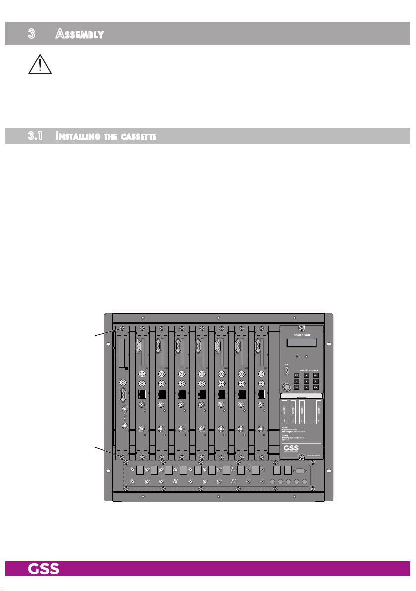
3.1 installi ng the C assette
– Ensure the head-end station is mounted so it will not be able to vibrate.
Avoid, for example, mounting the head-end station onto a lift shaft or any
other wall or floor construction that vibrates in a similar way.
– Before installing or changing a cassette unplug the power cable from the
mains power socket.
• Remove the fastening screws 1 of an unoccupied slot from the bracket of
the head-end station.
• Insert the cassette in this slot and push it into the housing.
• Align the cassette and apply slight pressure to connect it to the connections
of the board and the RF bus bar.
• Fasten the cassette with the screws 1.
1
1
- 10 - PADT 6400
Page 11
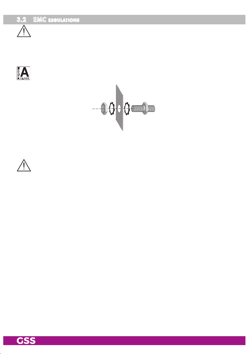
3.2 emC regulations
To comply with the current EMC regulations, it is necessary to connect the lines
leading in and out of the head-end station using cable terminals.
When mounting the cassette in a head-end station which is installed in a 19"
cabinet, make sure the connections leading in and out for the 19" cabinet are
made using cable terminals.
The attenuation of shielding of the connection lines for ASI and antenna must
KLASSE
CLASS
meet the requirements for "Class A".
• Insert the required number of cable terminals in the openings provided in
the head-end station or in the 19" cabinet.
Tighten the nuts on the cable terminals until the teeth on the lock washer have
penetrated the exterior coating and a good connection is made between the housing and cable terminals.
- 11 - PADT 6400
Page 12
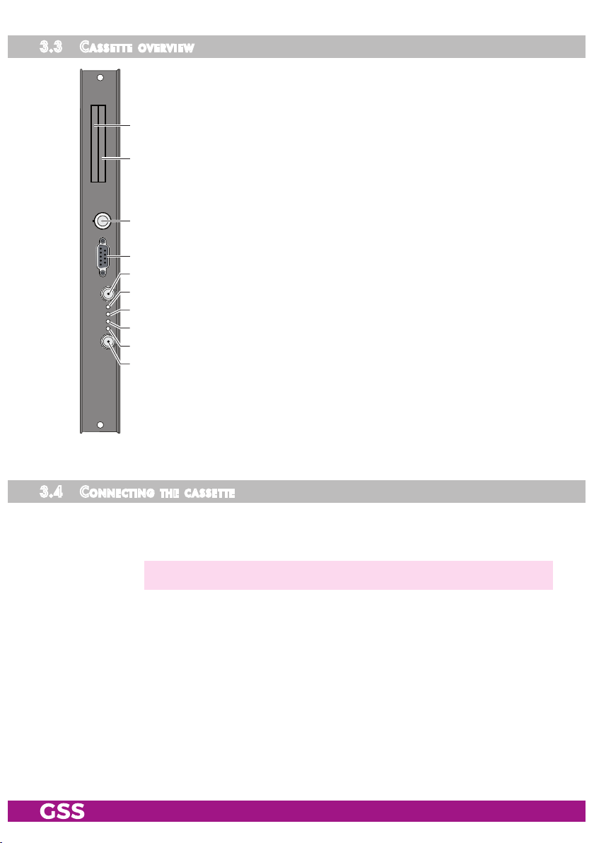
3.3 Cas sette overv iew
1 Slot for CA module of "tuner A"
2 Slot for CA module of "tuner C"
3 ASI input
1
4 D-SUB socket "RS 232"
5 SAT input "A"
2
6 Status LED of channel strip "A"
7 Status LED of channel strip "B"
3
8 Status LED of channel strip "C"
9 Status LED of channel strip "D"
0
4
5
6
SAT input "B"
7
The operating software of the cassette can be updated via the
8
9-pin D-SUB socket "RS 232" using a PC or notebook and the
9
software "BE-Flash". You can find the current operating software
0
on the website
"www.mygss.eu/en".
3.4 Con neCting the C a ssette
•
• If required connect the ASI input 3 to the ASI output of a corresponding
•
- 12 - PADT 6400
Connect "
of the SAT IF input distributors.
signal source.
Connect the head-end station to the mains power supply.
SAT input A
—> Avoid wide differences in level at the inputs!
" 5 and "
SAT input B
" 0 to the respective outputs
Page 13
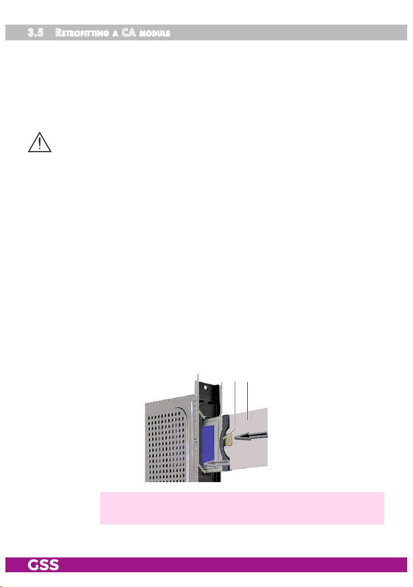
3.5 retr o fitting a Ca module
The cassette is equipped with two common interfaces. This allows you to con-
nect two CA modules for various scrambling systems and service providers.
Scrambled channels can only be descrambled with a CA module suitable for
the scrambling system and the corresponding smart card. The smart card contains all the information for authorisation, descrambling and subscription.
Caution
– Check with the distributor or manufacturer of the CA modules to be used
to ensure that they are suitable for descrambling several channels.
– The hardware and software of this cassette have been thoroughly prepared
and tested.
– Any changes made by programme provider to the structures in the pro-
gramme data might impair or even prevent this function.
– When working with the CA modules, please read the corresponding oper-
ating manuals from the respective providers.
• Insert the smart cards into the CA modules so that the chip 3 on the smart
card 1 faces the thicker side (top) of the CA module 2.
• Insert the CA modules into the slots 4 with the top sides of the CA modules
in left direction.
• Push the CA modules without canting into the guide rails of the CA slots 4
and contact them to the common interfaces.
3412
—> If the module is inserted in the head-end station, the left common
interface is assigned to tuner A, the right one to tuner C.
- 13 - PADT 6400
Page 14
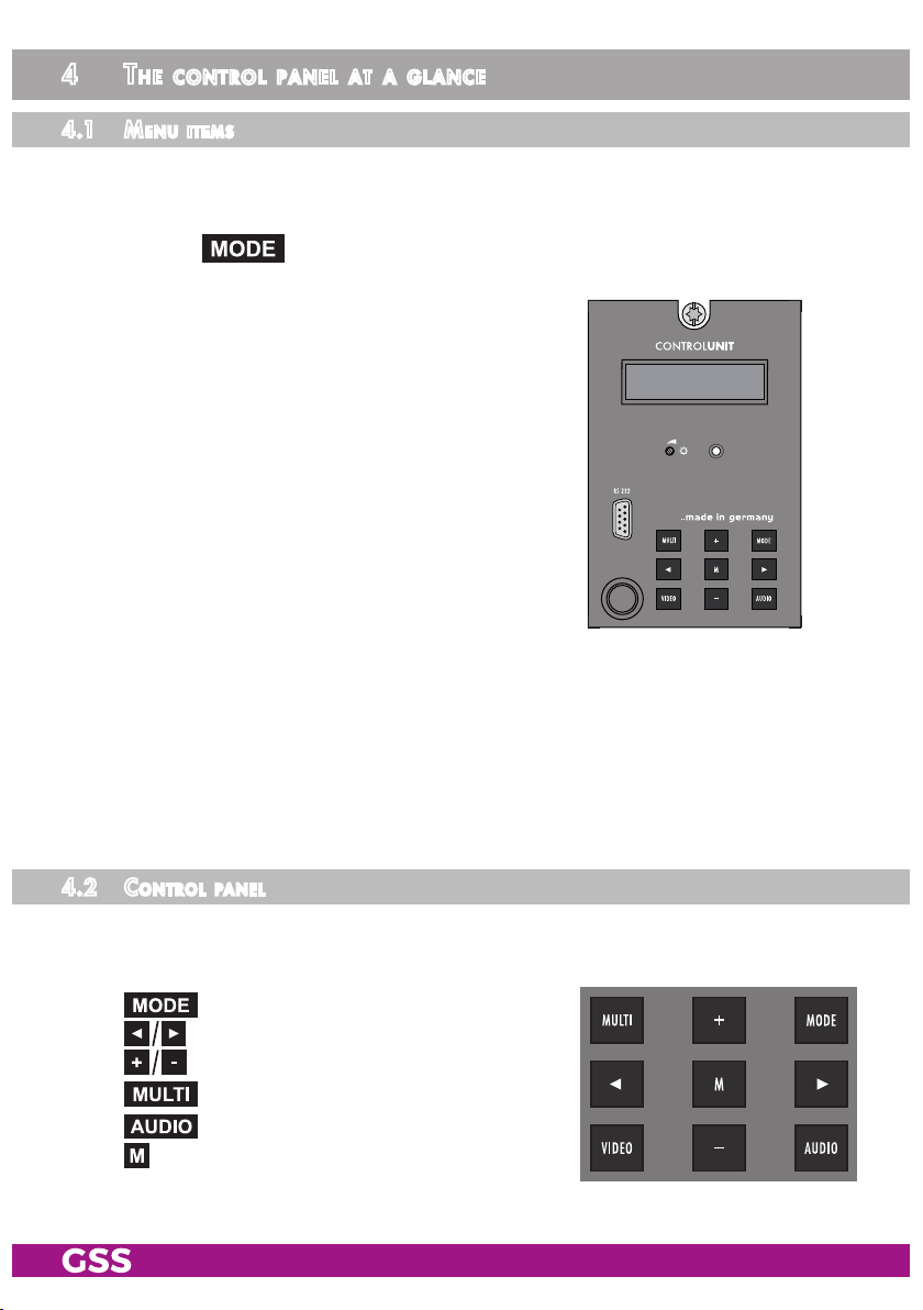
4 the Control Panel at a glanCe
4.1 menu i tems
Programme the
cassette
using the buttons on the control unit of the head-end
station. The two-line display of the control unit then shows the menus.
The parameters and functions to be set are underlined.
Use the key to select the following menu items:
– Output signal settings:
Modulator on/off, level
Output channel (modulators A and C)
Output frequency (modulators A…D)
Transmission parameters
BE-Re mote V 45
PROFESSION AL
Substitute signal
– ASI input
– Input signal settings:
LNB oscillator frequency
Input symbol rate
Input frequency
Station filter
CA module
Economize descrambling capacity
– Options:
Transport stream and ORGNET-ID
BAT, STD-other
Deleting a PID
Renaming a PID
– Data rate
– Network Information Table (NIT)
– Factory reset
4.2 Con trol Pane l
The key pad on the head-end station is used to scroll through the menus step-
by-step:
scrolls forward through the menus.
select parameters in the menus.
set values, initiate actions.
selects sub-menus.
scrolls backward through the menus.
saves all entries.
- 14 - PADT 6400
Page 15

5 Programming
5.1 Pre Par atio n
• Test the software versions of the head-end station and the cassette and up-
date them if necessary.
The current software versions can be found on the website
"
www.mygss.eu/en".
5.2
not e s on Programming
leve l setti ng
In order to prevent interference within the head-end station and the cable sys-
tem, the output level of the cassette must be decreased by 4dB compared to
an analogous level.
• Connect the test receiver to the RF output or the test output of the head-end
station.
• Set the output channel / output frequency of the
the TV test receiver to this channel / frequency.
•
Switch on the channel strip (modulator) if necessary (
nel strip, there is a status LED which indicates if the channel strip is switched
on
(6…9 page 12)
.
• Balance the output levels of the channel strips if the difference in level is
≥ 1 dB (page 20).
• Measure the output levels of the other cassettes and tune them to a uniform
output level using the appropriate level controls or software dependent on
the head-end station used. Please regard the assembly instructions of the
respective head-end station.
cassette
page
(page 21) and adjust
20). For each chan-
—> Avoid wide differences in level at the inputs!
ge n e r ati ng the nit v i a the Cont rol u nit
If you generate a new NIT via the control unit at mixed equipping with double
and quad cassettes, the NIT must be mandatory generated via the menu of a
quad cassette, in order to capture all transponders!
—> You have nothing to consider if you create the NIT via the PSW 1000.
- 15 - PADT 6400
Page 16

5.3 Progr am ming Pr o Cedure
Box 1
......... .....
........ ..... .
........ ..... .
Bx 1A
C5-12,S3- 24
TWIN-SAT
C07
Böx 4
C5-12,S3- 24
TWIN-SAT
C07
Box 5
......... .....
........ ..... .
........ ..... .
Ein / On
Modulator
A / B / C / D
BE–Remote
please wa it …
t > 10 s
+
Box 4
V 13
COFDM – – –
Bx 4
Mod A
V 45
4xDVBS2
OUTPUT
C66 =>
Bedienhinweise
"blättert" Menüs vorwärts.
"blättert" Menüs rückwärts.
wählen die Eingabeposition
wählt Untermenü
stellen Werte ein,.
speichert alle Eingaben.
1 zeigt die Eingabeposition
▶
Bx 4A
on
Mod A…D
Mod D…A
Bx 4A
C66
Mod A…D
Mod D…A
Bx 4A !
8MHZ QAM6 4
Mod A…D
Mod D…A
Bx 4A !
2k C7 /8
Mod A…D
Mod D…A
Bx 4A
CELL 0x0 000
Mod A…D
Mod D…A
Tables
Mod A…D
Mod D…A
LEVEL
– 3 dB
FREQ
834.00 MH z
COFDM–MODE
POS
COFDM–MODE
G1/32
COFDM TPS
FAILUREBx 4A
Operating Hints
scrolls forward through the menu.
scrolls backward through the menu.
select the enter position.
selects a submenu.
set values and triggers actions.
saves all entries.
1 shows the enter position
A
Page 18
B
on / off
◀
▶
0 … -20 dB
/
◀
▶
/
Frequenzabstand /
frequency separation
5…8MHz
QPSK…QAM64
◀
▶
/
positiv / negativ
positive / negative
! = DATARATE Over flow
C1/2 … C7/8
G1/4 … G 1/32
◀
▶
/
! = DATARATE Over flow
0x0000 … 0xFFFF
off
on / off
◀
▶
/
Tables / Single Carrier
A<–>BBx 4B
C<–>DBx 4D
- 16 - PADT 6400
Page 17

Box 1
......... .....
........ ..... .
........ ..... .
Bx 1A
C5-12,S3- 24
TWIN-SAT
C07
Böx 4
C5-12,S3- 24
TWIN-SAT
C07
Box 5
......... .....
........ ..... .
........ ..... .
FAILUREBx 4A
Tables
Tables / Single Carrier
Mod A…D
Mod D…A
Mod A…D
Mod D…A
Bx 4
0xASI
ASI
OFF
0xASI OFF Tuner A Tuner B Tuner C Tuner D 2
1xASI D Tuner A Tuner B
2xASI B/D Tuner A ASI Tuner C ASI
2xASI C/D Tuner A ASI
3xASI B/C/D Tuner A ASI ASI
4xASI A/B/C/D ASI ASI ASI ASI 0
Line A Line B Line C Line D CA
Tuner C ASI 2
Tuner B
ASI
ASI 1
2
1
Tuner/ASI
A / B / C / D
Bx 4
Tuner A
INPUT
OK =>
▶
9750 / 10600
22000 / 27500
alle + / alle –
all + / all –
on / off
Bx 4A
10600 MHz
Bx 4A
27500
Bx 4A
11835 +0.7
Das Erste
off
PID Check on
Bx 4A
PID 1:
LNB
In A
SYMBOL
DVB–S
FREQ
CN 9
01/06Bx 4A TV +
FILTERBx 4A
CA
SKIP CA
0x0000
In A / In B
◀
▶
/
◀
▶
/
◀
▶
/
+ aktiviert/activated
– deaktiviert/deactivated
◀
▶
/
X entschlüsseln/descramble
nur bei Auswahl Tuner A oder C
only if tuner A or C is selected
▶
Bx 4A 01/0 5
=>
nur Tuner A und C mit CA-Modul/
only tuner A and C with CA module
*) Die angezeigte Information ist abhängig
vom verwendeten CA-Modul.
The information displayed is dependent
on the CA module used.
▶
Informati on *)
MENUBx 4A
◀
▶
/
Bx 4
A
A / B / C / D
- 17 - PADT 6400
OPTIONS
=>
▶
Bx 4A
0x0001,01 00
A…D
D…A
Bx 4A
bat
A…D
D…A
TS/ONID
off
BAT/SDT
sdt–other
0x0000 … 0xFFFF
◀
▶
/
on / off
bat / BAT
◀
▶
/
sdt–other / SD T–OTH ER
Page 18

A / B / C / D
Box 1
......... .....
........ ..... .
........ ..... .
Bx 1A
C5-12,S3- 24
TWIN-SAT
C07
Böx 4
C5-12,S3- 24
TWIN-SAT
C07
Box 5
......... .....
........ ..... .
........ ..... .
Bx 4
A
OPTIONS
=>
TS/ONID
off
Bx 4A
0x0001,01 00
BAT/SDT
sdt–other
Bx 4A
bat
▶
bat / BAT
sdt–other / SD T–OTH ER
0x0000 … 0xFFFF
on / off
A…D
D…A
A…D
D…A
▶
◀
/
▶
◀
/
FILTERBx 4A
off
nur Tuner A und C mit CA-Modul/
only tuner A and C with CA module
*) Die angezeigte Information ist abhängig
vom verwendeten CA-Modul.
The information displayed is dependent
on the CA module used.
Bx 4A 01/0 5
Informati on *)
MENUBx 4A
PID Check onCA=>
▶
▶
▶
◀
/
Bx 4A
PID 1:
SKIP CA
0x0000
01/06Bx 4A TV +
Das Erste
▶
◀
/
alle + / alle –
all + / all –
nur bei Auswahl Tuner A oder C
only if tuner A or C is selected
on / off
+ aktiviert/activated
– deaktiviert/deactivated
X entschlüsseln/descramble
A / B / C / D
on / off
Bx 4A
A ! ! !
Bx 4A
off
Bx 4
Defaults
DATARATE
28/32 Mb
=> Make
FACTORY
NIT
=>
Bx 4A
0x0000
A…D
D…A
Bx 4A
0x0000–>0 000
A…D
D…A
aktuell/m ax.
current/m ax.
!!! Overf low
▶
Make
Bx 4
▶
STORE
FACTORY
=> M
DROP
off
◀
▶
/
off / on
REMAP
off
◀
▶
/
auf Werkseinstellung
zurücksetzen und speichern
M
reset to factory defaults
and store
off / on
Page 16
A
B
- 18 - PADT 6400
Page 19

5.4 Pro g r a m m i n g the Cass et te
Box 1
..............
..............
..............
Bx 1A
C5-12,S3-24
TWIN-SAT
C07
Böx 4
C5-12,S3-24
TWIN-SAT
C07
Box 5
..............
..............
..............
—> Pressing the button for longer than 2 seconds cancels the
programming procedure. This takes you back to the programme
item "Selecting the cassette" from any menu. Any entries that have
not been saved are reset to the previous settings.
—> Entries in the menus can be saved by pressing the key. You are
taken back to the "Selecting the cassette" menu item.
—> The cursor position for settings is shown by "_".
—> Dependent on the settings not needed menus are hidden.
• Switch on the head-end station
—> The display shows the software version (e.g. V45) of the control unit.
—> The processor reads the cassettes‘ data (approximately 10 seconds).
Ein / On
• Press the button.
—>
The "Selecting the cassette" – "Box x …" menu is activated.
seleC ting t he Cas s et te
+
• Select the
Box 4
V 13
cassette
4xDVBS2
COFDM – – –
you want to programme (e.g. Box 4) by repeatedly press-
ing the button if necessary.
—> The display shows e.g. the menu :
V 13 COFDM
"Box 4" stands for
"
4xDVBS2 COFDM
"V 13" Software version of the cassette
BE–Re mote
pleas e wai t …
V 45
t > 10 s
" Type of cassette
Box 4 4xDVBS2
slot
4
- 19 - PADT 6400
Page 20

• Press the button.
—>
The "Output settings" – "OUTPUT" main menu is activated.
out Put s e t tings
In this menu you select the modulator for which you would like to do the output
settings in the related submenus.
Bx 4
Mod A
—> In order to skip the "Output settings", press button
—> For example an indicated "C66" shows the current channel set. If
"C – –" is displayed a frequency which does not correspond to the
channel-/frequency grid was set.
—> It is possible to rotate through the submenus of all modulators using
the buttons (ascending) and (descending).
OUTP UT
C66 =>
.
• Using buttons select the desired modulator.
•
Press the
—> The "Modulator on/off, Level"
button.
– "LEVEL" submenu is activated.
modulat or on/off, le vel
This menu item is used to set the output levels of the four modulators to the
same value and to switch the modulators on or off.
Bx 4A
on
LEVE L
– 3 dB
• Measure and note down the output level of each modulator.
—> In order to adjust the output levels to the output levels of the other cas-
settes please pay attention to chapter "Final procedures" (page 45).
•
Using the buttons (ascending) or (descending)
activate the
"LEVEL" menus of all the modulators with higher output levels.
- 20 - PADT 6400
Page 21

• By pressi
ng adjust the higher output levels to the output level of the
modulator with the lowest output level incrementally.
• Use the button to place the cursor under "on" resp. "off".
•
Use the buttons to switch each modulator on or off.
• Press the button.
—> The "Channel / Frequency" – "FREQ" submenu is activated.
Chann el / frequen Cy
In this menu you can adjust the output channel (only at modulator A and C) or
the output frequency of the respective modulator.
—> The COFDM signal is normally transmitted with a bandwidth of
8 MHz. This means that you can only use the channel centre frequen-
cy of the existing channel grid in the range of channels C21…C69
(frequency grid 8 MHz). The CCIR channel grid is 7 MHz in the
range of the lower frequency bands (channels C5 … C12).
If 8 MHz COFDM signal packages are transmitted in these channel
ranges, this will result in interference (overlapping) and transmission
problems.
For programming in these channel ranges and in the frequency rang-
es below them, we recommend starting with frequency 306 MHz
going back in steps of 8 MHz (see frequency table on page 46).
Please note thereby that many receivers cannot receive the channel
ranges S21…S41 (306 … 466 MHz).
Channel setting (only modulators "A" and "C"):
Bx 4A
C66
—> The channel setting is only possible at modulators "A" and "C"
FREQ
834. 00 M Hz
Bx 4C
C68
FREQ
850. 00 M Hz
.
• Use buttons to select the cursor position for channel setting.
• Use buttons to adjust the desired channel.
- 21 - PADT 6400
Page 22

—> The modulators "B" and "D" by default are fixed to a spacing of
+ 8 MHz to the modulators "A" and "C". Only this spacing to the
modulators "A" and "C" can be set via the frequency setting.
Frequency setting (modulators "A" … "D"):
Bx 4A
834. 00 MHz
C66
FREQ
Bx 4B
C67
A <–> B
842. 00 MHz
Bx 4C
850. 00 MHz
C68
FREQ
Bx 4D
858. 00 MHz
C69
—> For modulators "A" and "C" any frequency (42,0 MHz …
860,0 MHz) can be set via the frequency setting.
For modulators "B" and "D" only this spacing to the the modulators
"A" and "C" can be set via the frequency setting.
• Use buttons to select the cursor position for frequency setting.
• Use buttons to adjust the desired frequency.
• Press the button.
—>
The "Output signal" – "COFDM-MODE" submenu is activated. Please
take note of the tables below before setting the COFDM parameters.
C <–> D
- 22 - PADT 6400
Page 23

Cofdm Parameters
The tables below show the dependence of the transmittable net data rate on
the settings of the COFDM parameters.
The conversion of the net data rate into the gross data rate displayed in the
"Output data rate" menu (page 42) is made according to the following formula
204 x net data rate
Gross data rate =
188
Net data rate [kbit/s]
at a bandwidth of 8 MHz
Guard interval
1
/
8
1
/
1
16
/
32
Modulation Code rate
1
/
2
2
/
3
QPSK
16 QAM
64 QAM
3
/
4
5
/
6
7
/
8
1
/
2
2
/
3
3
/
4
5
/
6
7
/
8
1
/
2
2
/
3
3
/
4
5
/
6
7
/
8
1
/
4
4976 5529 5855 6032
6635 7373 7806 8043
7465 8294 8782 9048
8294 9216 9758 10053
8709 9676 10246 10556
9953 11059 11709 12064
13271 14745 15612 16086
14929 16588 17564 18096
16588 18431 19516 20107
17418 19353 20491 21112
14929 16588 17564 18096
19906 22118 23419 24128
22394 24882 26346 27144
24882 27647 29273 30160
26126 29029 30737 31668
:
- 23 - PADT 6400
Page 24

If the bandwidth is decreased by 1 MHz the transmittable data rate is de-
creased by approx. 1/8.
Net data rate [kbit/s]
at a bandwidth of 7 MHz
Guard interval
1
/
8
1
/
16
Net data rate [kbit/s]
at a bandwidth of 6 MHz
Guard interval
1
/
8
1
/
16
1
/
32
1
/
32
Modulation Code rate
1
/
2
2
/
3
QPSK
16 QAM
64 QAM
3
/
4
5
/
6
7
/
8
1
/
2
2
/
3
3
/
4
5
/
6
7
/
8
1
/
2
2
/
3
3
/
4
5
/
6
7
/
8
Modulation Code rate
1
/
2
2
/
3
QPSK
16 QAM
64 QAM
3
/
4
5
/
6
7
/
8
1
/
2
2
/
3
3
/
4
5
/
6
7
/
8
1
/
2
2
/
3
3
/
4
5
/
6
7
/
8
1
/
4
4354 4838 5123 5278
5806 6451 6830 7037
6532 7257 7684 7917
7257 8064 8538 8797
7620 8467 8965 9237
8709 9676 10246 10556
11612 12902 13661 14075
13063 14515 15369 15834
14515 16127 17076 17594
15240 16934 17930 18473
13063 14515 15369 15834
17418 19353 20491 21112
19595 21772 23053 23751
21772 24191 25614 26390
22861 25401 26895 27710
1
/
4
3732 4147 4391 4524
4976 5529 5855 6032
5599 6221 6587 6786
6221 6912 7318 7540
6532 7257 7684 7917
7465 8294 8782 9048
9953 11059 11709 12064
11197 12441 13173 13572
12441 13824 14637 15080
13063 14515 15369 15834
11197 12441 13173 13572
14929 16588 17564 18096
16796 18662 19760 20358
18662 20735 21995 22620
19595 21772 23053 23751
- 24 - PADT 6400
Page 25

Transmission parameters for DVB-T
at a bandwidth of 8 MHz
Transmission mode 2k
Symbol duration T
Carrier space ∆ f [kHz]
(n
carrier) theoretical
(n
carrier) real
Used bandwidth [MHz]
Total symbol duration
T
[µs]
GS
Guard interval T
T
/ T
G
S
G
[µs]
S
[µs]
224
4.4643
2048
1705
7.61
280 262 238 231
56 28 14 7
1
/
4
1
/
8
Transmission parameters for DVB-T
at a bandwidth of 7 MHz
Transmission mode 2k
Symbol duration T
Carrier space ∆ f [kHz]
(n
carrier) theoretical
(n
carrier) real
Used bandwidth [MHz]
Total symbol duration
T
[µs]
GS
Guard interval T
T
/ T
G
S
G
[µs]
S
[µs]
224
4.4643
2048
1705
6.66
320 288 272 264
64 32 16 8
1
/
4
1
/
8
1
/
1
/
1
16
16
/
32
1
/
32
Transmission parameters for DVB-T
at a bandwidth of 6 MHz
Transmission mode 2k
Symbol duration T
Carrier space ∆ f [kHz]
(n
carrier) theoretical
(n
carrier) real
Used bandwidth [MHz]
Total symbol duration
T
[µs]
GS
Guard interval T
T
/ T
G
S
G
[µs]
S
[µs]
224
4.4643
2048
1705
5.71
373 336 317 308
74.7 37.3 18.7 9.3
1
/
4
1
/
1
8
/
1
16
/
32
- 25 - PADT 6400
Page 26

outPu t signal
In this menu, you can set the bandwidth, the carrier modulation and the spectral
position of the output signal.
COFDM–MODE
Bx 4A !
8MHZ QAM6 4
POS
Bandwidth of the output signal
To transmit the output signal in the channel range of C21 to C69 a bandwidth
of 8 MHz can be used.
In the channel range of C5 to C12 a bandwidth of ≤ 7 MHz must be set.
If frequency setting is selected you can set the bandwidth dependent on the
frequency of the adjacent channel.
COFDM–MODE
Bx 4A !
8MHZ QAM6 4
POS
•
Use to set the bandwidth of the output signal ("5MHz" … "8MHz").
Carrier modulation
In this menu item the carrier modulation is set. At this the setting "QPSK" corre-
sponds to the lowest and the setting "QAM64" to the highest output data rate.
• Use the buttons to place the cursor under "
QPSK / QAM…
".
• Set the carrier modulation of the output signal using the buttons
("QPSK", "QAM16", "QAM64").
—> A displayed "!" indicates an output data rate overflow (page 42).
COFDM–MODEBx 4A !
Spectral position – inverting the user signal
For exceptional cases and "older" digital cable receivers, the spectral position
of the user signal can be inverted "NEG"
. The default setting is
"POS".
• Use to place the cursor under "POS".
• Use to set the spectral position to "NEG".
• Press the button.
- 26 - PADT 6400
Page 27

—> The "Transmission parameters" – "COFDM-MODE" submenu is acti-
vated.
tr ansmiss i o n Pa r a m eters
In this menu you can set the code rate and the guard interval.
COFDM–MODE
Bx 4A !
2k C7/8
—> The 2k transmission mode is fixed.
2k mode: 1512 carrier for user data (total 1705 carriers)
—> A displayed "!" indicates an output data rate overflow (page 42).
G1/32
COFDM–MODEBx 4A !
Code rate
During a transmission, data can be lost or changed. To recover this data, redun-
dancy is added to the signal to be transmitted (forward error correction). The
factor of the quantity of redundancy contained in the bits transmitted is called
code rate.
Using the setting "C7/8" you can get the highest output data rate at lowest re-
dundancy.
• Use the buttons to place the cursor under "C…
".
• Set the code rate required using the buttons ("C1/2", "C2/3",
"C3/4", "C5/6", "C7/8").
Guard interval
In this menu item you set the relation of the duration of the user symbols to the
duration of the guard intervals to be transmitted. A high guard interval, e.g.
"G1/4"
causes a low output data rate. For cable networks the setting "G1/32"
is adequate.
• Use the buttons to place the cursor under "G…
".
• Set the guard interval required using the buttons ("G1/4", "G1/8",
"G1/16", "G1/32").
• Press the button.
- 27 - PADT 6400
Page 28

—> The "Transmitter identification" – "COFDM TPS" menu is activated.
tr ansmitte r iden tifiCation
At terrestrial transmission an identification is referred to each COFDM modu-
lated transmitter. When COFDM modulated signals are fed into cable net-
works this identification is not necessary usually. If receiving problems should
occur you must refer a transmitter identification (CELL ID) to each output chan-
nel and switch "on" the transmitter identification.
Bx 4A
CELL 0x 0000
COFDM TPS
off
• Use the buttons to position the cursor under the digit of the hexadeci-
mal number to be set.
•
Press to set the respective digit of the hexadecimal number.
• Repeat the procedure by the quantity of the digits to be set.
• Using the button place the cursor under "off" and switch "on" the trans-
mitter identification using the buttons.
—>
By pressing the
setting
.
button you return to the hexadecimal number
• Press the button.
—> The "Substitute signal in the case of an incorrect input signal" –
"FAILURE" submenu is activated.
- 28 - PADT 6400
Page 29

subst itute signal i n the C a se of a n inCo rreCt inPut s ignal
You use this menu to set whether a
and self-made tables
"Tables"
COFDM
signal filled with null packets
or a "Single Carrier" signal should be provided as an output signal whenever an incorrect input signal occurs. Selfmade tables are transmitted furthermore.
FAILUREBx 4A
Tables
• Use the buttons to set the required output signal.
• Press the button.
—> Returning to "Output settings" main menu (page 20).
—> If necessary set further modulators.
• Press the button.
—> The "ASI input" – "
ASI
" main menu is activated.
asi i n Put
In this menu you can assign the ASI input instead of the tuners as the source
for the channel strips (lines).
Bx 4
0xASI
ASI
OFF
The following settings are available:
Line A Line B Line C Line D CA
0xASI OFF Tuner A Tuner B Tuner C Tuner D 2
1xASI D Tuner A Tuner B Tuner C ASI 2
2xASI B/D Tuner A ASI Tuner C ASI 2
2xASI C/D Tuner A Tuner B ASI ASI 1
3xASI B/C/D Tuner A ASI ASI ASI 1
4xASI A/B/C/D ASI ASI ASI ASI 0
- 29 - PADT 6400
Page 30

• Use the buttons to set the required numbers of lines using the ASI
input signal.
—> On the left side you select the number of "ASI lines", on the right
side you see, which lines are used.
• Press the button.
—> The "Input settings" – "
INPUT
" main menu is activated.
inPut settin gs
In this menu you select the tuner for which you would like to do the input set-
tings in the related submenus.
•
•
Bx 4
Tuner A
—> In order to skip the "Input settings", press button
—> "OK" indicates a present input signal.
Using the buttons select the desired channel strip ("A"…"D").
—> Dependent on the "ASI input selection" (page 29) you will get "Tuner"
or "ASI" for selection. If "line" is displayed you will only get access
to the station filter settings. IF "tuner" is displayed, in addition you
get access to the tuner settings and if a CA module is retrofitted the
corresponding CA menu is available.
Press button
.
INPU T
OK = >
Bx 4
ASI B
INPUT
OK =>
.
Input signal source ASI:
—> The "Station filter" – "e.g. 01/06" submenu is activated (page 33).
Input signal source Tuner:
—> The "LNB oscillator frequency, Input" – "
LNB
" menu is activated.
- 30 - PADT 6400
Page 31

lnb o sCillat o r fr equenCy, inPut
—> This menu is only displayed if "Tuner" is selected as input signal
source (page 29).
In this menu select the SAT input and set the oscillator frequency of the LNB
used.
Bx 4A
1060 0 MH z
LNB
In A
• Use buttons to place the cursor under the digit to be set for the oscillator frequency displayed.
• Press buttons to enter the respective digit of the oscillator frequency
of the LNB used.
• Repeat the procedure by the quantity of the digits to be set.
• Use button to place the cursor under "In A" resp. "In B".
• Press buttons to select the respective SAT input ("A" or "B").
• Press the button.
—> The "Input symbol rate, DVB mode" – "SYMBOL" submenu is activated.
inPut sym b o l rat e, dvb m o d e
—> This menu is only displayed if "Tuner" is selected as input signal
source (page 29).
In this menu set the symbol rate of the desired transponder. The DVB mode is
indicated.
Bx 4A
2750 0
SYMB OL
DVB– S
Symbol rate:
The symbol rates of the satellite transponders can be found in the current chan-
nel table of the satellite operator, in various satellite magazines and in the
Internet.
- 31 - PADT 6400
Page 32

• Use to position the cursor under the digit to be set for the symbol rate
displayed.
• Press
to enter the respective digit of the symbol rate needed.
• Repeat the procedure by the quantity of the digits to be set.
DVB mode:
The cassette recognizes the transmitted DVB mode and switches over between
the normal QPSK mode (DVB-S) and the DVB-S2 mode.
• Press the button.
—> The "Input frequency" – "FREQ" submenu is activated.
inPut freq u e n Cy
—> This menu is only displayed if "Tuner" is selected as input signal
source (page 29).
If three dots " … " appear in the second line of the display, the cassette is in
the "station search" mode. Please wait until the process has finished.
Once the RF receiver has synchronised to the input signal, any offset to the
target frequency is displayed in MHz, e.g. "– 1.8".
If a question mark "?" appears in the second line of the display, there is no
input signal present. In this case check the configuration of the antenna system
and head-end station as well as the preceding settings of the cassette.
Bx 4A
11835 +0. 7
FREQ
CN 9
• Use to position the cursor under the digit of the frequency displayed
to be set.
•
Press to set the respective digit of the input frequency needed.
• Repeat the procedure by the quantity of the digits to be set.
• Set the frequency offset shown in the display (e.g. "– 1.8") to less than
1MHz ("± 0.x") by varying the input frequency using the buttons.
- 32 - PADT 6400
Page 33

Signal to noise ratio:
1
2
3
"CN …" indicates the current signal to noise ratio, in order to estimate the
quality of the input signal.
—>
In addition to the indicator in the display, there is also a status LED
which indicates the quality of the received transport stream
:
7 Status LED channel strip B
8 Status LED channel strip C
9 Status LED channel strip D
4
5
6
7
8
9
0
6 Status LED channel strip A
LED
indicator
Green Signal quality is good
Orange Signal quality is poor
Red No signal
Red<–
>Green
Off Channel strip (modulator) off
Data rate overflow (output)
Indication
• Press the button.
—>
The "Station filter – Selection" – e.g. "01/06" submenu is activated.
oPerat i o n with a Ca m o dule
In order to descramble scrambled channels a corresponding smart card is
needed.
The channels to be descrambled are set in submenu "station selection".
stati on fi lte r – se leCti on
In this menu stations (services) of a transponder can be switched off.
Herein you select which scrambled station should be descrambled using an
adequate CA module (only via tuner "A" and "C").
01/06Bx 4A TV +
Das Erst e
- 33 - PADT 6400
Page 34

—> All stations from the channel strip will be read, and then displayed
with name and station type.
—> If no station is found, the following message will appear in the dis-
play: "FILTER no Service".
In this case, check the configuration of the antenna system and
head-end station, as well as the previously adjusted settings for the
cassette.
—> By default all stations of the transport stream are activated.
—> The display shows e.g.:
Das Erste
Meaning of the indicators in the example:
"Bx 4A" Slot 4, channel strip "A"
"TV" TV channel type
" + "
"
01/06" The 1st of 6 stations is being displayed.
"
Das Erste
Further possible terms displayed:
"RA" Radio channel type
For radio stations, the back
" – "
" * " The star means that the TV or radio station selected is
The currently
" Station name
connected TV or test receiver is darkened.
The currently selected station is
scrambled. To enable the station, the CA module and
the appropriate smart card of the station provider are
required.
Bx 4A TV + 01/06
selected
station is switched on.
ground of the screen of the
switched off.
—> If a service number (e.g. "131") appears instead of "TV" or "RA",
this indicates that an unnamed station or an undefined data stream
is being received.
•
Use the buttons to call up the stations in sequential order, then use
to activate (indicated by " + ") or to deactivate them (indicated by " – ").
—> If you deactivate any station, the station filter in the following menu is
activated (on).
—> Using button all station can be activated/deactivated.
—> If a station is scrambled (indication "*"), in this menu you select
whether it should be descrambled using an adequate CA module
(only possible via tuner "A" and "C").
- 34 - PADT 6400
Page 35

• Press button twice to descramble a station (indication "X").
01/06Bx 4A TV * X
• Press the button.
—> The "Station filter on/off" – "FILTER" submenu is activated.
stati on fi lte r on/off
Herein you can switch on resp. off the station filter. This influences the behav-
iour of the cassette when changing the station assignment of the input signals.
FILTERBx 4A
off
– Filter on: Only stations which are selected (+) in menu Station filter – Selec-
tion will be passed. New stations will be blocked until they will be activated
in the Station filter – Selection menu (+).
– Filter off: All stations will be passed – also "new" stations – this may cause
data overflow at the output!
—> The menus Station filter on/off and Station filter – Selection influ-
ence each other:
If a station will be deactivated (–) in the Station filter – Selection
menu, the station filter is activated (on).
If the station filter will be switched off in menu Station filter on/off,
all deactivated stations are activated in the Station filter – Selection
menu (+).
• Use the buttons to switch "on" or "off" the station filter.
• Press the button.
Input signal source ASI:
—> Returning to "Input settings"
If necessary set further channel strips.
Input signal source Tuner:
—> The "PID monitoring" – "CA" sub
- 35 - PADT 6400
- "INPUT"
main menu (page 30).
menu is activated
.
Page 36

Pid m o nitor ing
—> This menu is only displayed if "Tuner" is selected as input signal
source (page 29).
In this menu you can switch off the PID monitoring and call up a menu for the
settings of the CA module (dependent on the CA module).
Bx 4A
PID Check onCA=>
—> If tuner B or D is selected, this menu is out of order.
Indication:
Bx 4B/D CA
– –
PID monitoring:
—> The factory default of the PID monitoring is switched on.
If particular PIDs are not descrambled the CA module is reset. Ad-
ditionally dropouts may occur if several stations are descrambled.
To prevent this the PID monitoring can be switched off.
• Use the buttons to switch "off" or "on" the PID monitoring.
• Use the button to activate the menu of the CA module (only if Tuner "A"
or "B" is selected).
—> Access to this menu is only possible with installed CA module and
inserted smart card.
- 36 - PADT 6400
Page 37

Ca mo dule
—> This menu is only displayed if "Tuner A/C" is selected as input sig-
nal source (page 29) and a CA module is installed.
The menu varies according to which CA module you are using. For this rea-
son, please refer to the operating manual of your particular CA module. The
relevant information is shown in the display of the head-end station. This may
appear as a fixed display or as scrolling text according to display capabilities.
▶
▶
Bx 4A 01/05
Information *)
MENU
Bx 4A
PID Check on
—> The display shows e.g.: Bx 4A 01/05 MENU
Meaning of the indicators:
"Bx 4A" Slot 4, channel strip "A"
"
01/05
"
MENU
CA
=>
" The first of five menu items is activated.
" The menu of the CA module is activated.
*) For the explanation of further details please use the operating instructions of
the CA module used.
• Use the buttons to activate the menu desired.
• Press the button to activate the menu.
• Use the buttons to select the function desired.
• To set the CA module use the and buttons.
—> By pressing the button you can cancel the settings in the
menu of the CA module and are returned to the "PID monitoring" –
"CA" menu.
• All settings are saved by pressing the button.
—> You will be returned to the "PID monitoring" – "CA" menu.
• Press the button.
—> The "Economize descrambling capacity" – "SKIP CA" is activated.
- 37 - PADT 6400
Page 38

eCon omize d esCramblin g CaPaCit y
Bx 4B/D SKIP CA
– –
—> This menu is only displayed if "Tuner" is selected as input signal
source (page 29).
In this menu up to 9 not needed PIDs (e.g. audio PIDs of foreign language
versions) can be excluded from the descrambling in order to economize descrambling capacity.
—> If tuner B or D is selected, this menu is out of order.
Indication:
Bx 4A
PID 1:
SKIP CA
0x0000
• Using buttons select the desired memory location
(PID 1…9) .
• Use to position the cursor under the digit of PID to be set.
•
Press to set the respective digit of the PID needed.
• Repeat the procedure by the quantity of the digits to be set.
—> If required select another memory location and enter the next PID
which shall not descrambled.
—> To delete a stored PID, overwrite it by "0000".
• Press the button.
—> Returning to "Input settings"
—> If required set further channel strips.
- "INPUT"
main menu (page 30).
• Press the button.
The "Option settings" – "OPTIONS" main
menu is activated
.
- 38 - PADT 6400
Page 39

oPtion s e t tings
In this menu you select the channel strip for which you would like to do the
option settings in the related submenus.
Bx 4
A
—> In order to skip the "Option settings", press button
OPTI ONS
=>
.
• Using the buttons select the desired channel strip ("A"…"D").
•
Press button
—> The "Transport stream ID and ORGNET-ID" – "TS/ONID" menu is
.
activated.
tr ansPort stre am id a n d orgnet-id
If the stations of a transponder are split into the transport streams of several
channel strips, a new identification must be allocated to the further transport
streams to realise the channel search of the settop boxes connected without
mistakes.
—> If the ORGNET-ID is changed also a new NIT must be generated
(page 42).
Bx 4A…D
0x0001,0100
TS/ONID
off
• Use the buttons to position the cursor under the digit of the hexadecimal number to be set.
•
Press to set the respective digit of the hexadecimal number.
• Repeat the procedure by the quantity of the digits to be set.
• Using the button place the cursor under "off" and switch "on" the transmitter identification using the buttons.
—>
By pressing the
setting
.
button you return to the hexadecimal number
• Press the button.
- 39 - PADT 6400
Page 40

—> The "BAT/SDT-OTHER tables" – "BAT/SDT" submenu is activated.
bat/sdt-other tables
In this menu you can switch on resp. off the BAT- and SDT-OTHER tables.
—> BAT = Bouquet Association Table:
Information in the data stream about the affiliation of station packets
to a specific bouquet.
—> SDT-OTHER = Service Description Table – OTHER data streams:
Information in the data stream about service parameter of other data
streams.
Bx 4A
bat
BAT/SD T
sdt– othe r
• Using the button place the cursor under "bat" and switch "on" ("BAT")
or "off" ("bat") the bouquet association table using the buttons.
• Using the button place the cursor under "sdt-other" and switch "on"
("SDT-OTHER") or "off" ("sdt-other") the service description table using the
buttons.
—> Capital letters: Function activated
Lower case letters: Function deactivated (factory default)
• Press the button.
—> The "Deleting a PID" – "DROP" submenu is activated.
- 40 - PADT 6400
Page 41

deleti ng a Pid
In this menu a PID of the transport stream can be deleted.
Bx 4A
0x00 00
DROP
off
• Use the buttons to place the cursor under the respective digit of the
hexadecimal number of the PID to be deleted ("0x0000") and set the hexadecimal number using .
• Use the
button to set the cursor under "
off
" and
delete the PID
using the
buttons ("on").
• Press the button.
—> The "Renaming a PID" – "REMAP" submenu is activated (page 41).
renaming a Pid
In this menu you can allocate a new address to a PID retaining the complete
data content.
Bx 4A
0x00 00–> 0000
REMAP
off
• Use the buttons to place the cursor under the respective digit of
the hexadecimal number of the PID to be changed ("0x0000") and set the
hexadecimal number using .
• Use the buttons to place the cursor under the respective digit of the
hexadecimal number of the new PID ("–> 0000").
• Set the hexadecimal number using .
• Use the button to set the cursor to "off" and rename the PID using the
buttons ("on").
• Press the button.
—> Returning to "Option settings" main menu (page 39).
—> If required set further channel strips.
• Press the button.
The "Output data rate" – "DATARATE" main
- 41 - PADT 6400
menu is activated
.
Page 42

outPu t data r ate
This menu shows the output data rate defined using the COFDM settings and
the current output data rate.
Bx 4
A ! ! !
DATARATE
28/32 Mb
28: The current measured gross output data rate.
32: Maximum gross output data rate.
If the station filter is set correctly, current data rate is lower than the maximum
data rate. The value fluctuates, since the data rates of individual stations are
dynamically modified by the broadcasters.
—> Is the current data rate higher than the maximum data rate excla-
mation marks "!!!" appear in the display. In this case correct the
COFDM settings (pages 26 …) or the settings of the station filter
(page 33).
Bx 4
A ! ! !
DATARATE
34/32 Mb
• Press the button.
—> The "Network Information Table" – "NIT" main menu is activated.
networ k info rm ati on table (nit)
Bx 4
off
NIT
=> Make
• To switch NIT "on" resp. "off" press the buttons.
• Press the button to activate NIT ("Make").
All active cassettes which are able to output a NIT ("NIT cassettes") must be
set and ready for reception.
—> The NIT of all "NIT cassettes" are switched on.
- 42 - PADT 6400
Page 43

—> The cassette fetches all the information (output frequencies, output
data rates, etc.) it needs from all the "NIT cassettes" in order to
generate the NIT. This process may take a few seconds.
Then the NIT is generated, added and sent to all "NIT cassettes".
The other "NIT cassettes" also add this new NIT. The status of all
"NIT cassettes" in the NIT menu changes to "on".
The display shows: "read … / copy …".
• To switch off the new NIT
—>
The NITs of the other "NIT c
the NIT of the cassette is
button, the previously generated NIT is added again. If you have
changed parameters in the meantime, you must first select "
to generate a new, up-to-date NIT.
• Press the button.
—> The "Factory reset" – "FACTORY Defaults" menu is activated.
("off")
press the
button.
assettes"
switched on again ("on") by pressing the
will
stay switched on. When
Make
"
- 43 - PADT 6400
Page 44

faCto ry r e set
In this menu you can reset all settings to the factory defaults.
Bx 4
Defa ults
FACTORY
• Press the button.
—> The factory defaults are invoked ("FACTORY STORE")
—> By pressing the button, you will be returned to the menu
item "Output settings" without
• Press the button.
—> The factory defaults are saved
The display shows "STORE"
—> Back to "Selecting the cassette" (page 19).
—> By pressing the button, you will be returned to the menu
item "Output settings" without
—> If required set further channel strips.
saving s et tings
=>
▶
Bx 4
STORE
FACTORY
=> M
invoking the factory defaults
.
saving the factory defaults
M
.
(page 20).
(page 20).
• Press the button.
—> Returning to "Selecting the cassette" menu (page 19).
—> The settings are saved.
—> If functions of the TPS module are activated, their status is shown in
the second line of the menu:
"M" – Station filter is switched on.
"N" – NIT is activated.
—> If required set further channel strips.
- 44 - PADT 6400
Page 45

6 fi n a l ProCedures
After installing the head-end station, upgrading accessories or installing cas-
settes it is necessary to tighten all cable connections, cable terminals and cover
screws in order to maintain compliance with current EMC regulations securely.
• Securely tighten the cable connections using an appropriate open-ended
spanner.
• Measure the output levels of the other cassettes and tune them to a uniform
output level using the appropriate level controls or software dependent on
the head-end station used. Please regard the assembly instructions of the
respective head-end station.
• Mount the front cover (see assembly instructions of the head-end station).
- 45 - PADT 6400
Page 46

7 Channel and frequenCy tables
Advice for a frequency grid (8 MHz) in the band I/III
]
[MHz
Frequenz
Frequency
42.00
50.00
58.00
66.00
74.00
Channel-/frequency grid for DVB-T (band III, bandwidth 7 MHz)
]
Kanal
Channel
C 5 177.5
C 6 184.5
C 7 191.5
[MHz
Frequenz
Frequency
CCIR – Hyperband (frequency grid 8 MHz)
]
[MHz
Frequenz
Frequency
82.00
114.00
122.00
130.00
138.00
Kanal
Channel
C 8 198.5
C 9 205.5
C 10 212.5
Frequenz
146.00
154.00
162.00
170.00
178.00
]
[MHz
Frequenz
Frequency
]
[MHz
Frequency
Kanal
C 11 219.5
C 12 226.5
186.00
194.00
202.00
210.00
218.00
Channel
Frequenz
]
[MHz
Frequenz
Frequency
]
[MHz
Frequency
Frequenz
Frequency
226.00
234.00
242.00
250.00
258.00
]
[MHz
Frequenz
266.00
274.00
282.00
290.00
298.00
]
[MHz
Frequency
Kanal
Channel
Kanalmittenfrequenz
Channel centre frequency
S 21 306.00
S 22 314.00
S 23 322.00
S 24 330.00
S 25 338.00
]
[MHz
Kanal
S 26 346.00
S 27 354.00
S 28 362.00
S 29 370.00
]
[MHz
Channel
Kanalmittenfrequenz
Channel centre frequency
Kanal
Channel
Kanalmittenfrequenz
Channel centre frequency
S 30 378.00
S 31 386.00
S 32 394.00
S 33 402.00
]
[MHz
Kanal
Channel
Kanalmittenfrequenz
Channel centre frequency
S 34 410.00
S 35 418.00
S 36 426.00
S 37 434.00
]
[MHz
Kanal
Channel
Kanalmittenfrequenz
Channel centre frequency
S 38 442.00
S 39 450.00
S 40 458.00
S 41 466.00
]
[MHz
CCIR – Band IV/V (frequency grid 8 MHz)
C 21 474.00
C 22 482.00
C 23 490.00
C 24 498.00
C 25 506.00
C 26 514.00
C 27 522.00
C 28 530.00
C 29 538.00
C 30 546.00
- 46 - PADT 6400
C 31 554.00
C 32 562.00
C 33 570.00
C 34 578.00
C 35 586.00
C 36 594.00
C 37 602.00
C 38 610.00
C 39 618.00
C 40 626.00
C 41 634.00
C 42 642.00
C 43 650.00
C 44 658.00
C 45 666.00
C 46 674.00
C 47 682.00
C 48 690.00
C 49 698.00
C 50 706.00
C 51 714.00
C 52 722.00
C 53 730.00
C 54 738.00
C 55 746.00
C 56 754.00
C 57 762.00
C 58 770.00
C 59 778.00
C 60 786.00
C 61 794.00
C 62 802.00
C 63 810.00
C 64 818.00
C 65 826.00
C 66 834.00
C 67 842.00
C 68 850.00
C 69 858.00
Page 47

Declaration of CE conformity
GSS Grundig Systems GmbH • Beuthener Straße 43 • D-90471 Nuremberg
Phone: +49 (0) 911 / 703 8877 • Fax: +49 (0) 911 / 703 9210
www.gss.de/en • info@gss.de
KLASSEKLASSE
CLASSCLASS
Service: Phone: +49 (0) 911/703 2221; Fax: +49 (0) 911/703 2326; service@gss.de
Alterations reserved. Technical data E. & O.E. © by GSS Grundig Systems GmbH V13/001/2017
 Loading...