


Montageanleitung
Assembly Instruction
A
CLASS
KLASSE
Grundig SAT SystEms
Head-End Receiver Converter
HRC 312 AV S
English
Assembly Instruction
GSS
Grundig SAT Systems GmbH
Beuthener Strasse 43
Montageanleitung
D-90471 Nuernberg, Germany
Phone: +49 (0) 911 / 703 8877
Fax: +49 (0) 911 / 703 9210
E-mail: info@gss.tv
Internet: http://www.gss.tv
A
KLASSE
CLASS

- 2 -
Contents
1 Safety regulations ................................................................................................3
2 General information ............................................................................................3
2.1 Scope of delivery ................................................................................... 3
2.2 Technical specifications .......................................................................... 4
2.3 Description ........................................................................................... 5
2.3.1 Display of the control unit software version ..................................... 5
3 Installation ..........................................................................................................6
3.1 Installation of the modulators ................................................................... 6
3.2 Installing the cassette in the head end ....................................................... 8
3.3 Connecting the cassette .......................................................................... 8
4 The control panel at a glance ...............................................................................9
4.1 Menu items ........................................................................................... 9
4.2 Control panel ........................................................................................ 9
5 Programming ....................................................................................................10
5.1 Preparation ......................................................................................... 10
5.2 The menus at a glance ........................................................................ 10
5.3 Programming the cassette ..................................................................... 12
Selecting the cassette ........................................................................... 12
Selecting a modulator .......................................................................... 13
Setting the output level .......................................................................... 13
Switching the modulator on/off ............................................................. 14
Setting the TV standard ......................................................................... 14
Selecting channel / frequency input ....................................................... 15
Setting the output channel / output frequency .......................................... 15
Setting the frequency offset (fine tuning) .................................................. 16
Adjusting the video level ....................................................................... 16
Setting the modulation depth (fine tuning) ............................................... 17
Setting the audio carrier amplitude ........................................................ 17
Setting the audio type .......................................................................... 18
Setting the audio output level ................................................................ 18
Saving settings .................................................................................... 18
Channel and frequency tables ................................................................................ 19
I. Band I / III .......................................................................................... 19
II. Hyperband ......................................................................................... 20
III. Band IV / V ........................................................................................ 21
- 2 -

- 3 -
1 Safety regulations
Caution
• The converter should be assembled, installed and serviced by authorised electricians.
• Switch off the operating voltage of the system before beginning with assembly
or service work or pull the mains plug.
• Install the system …
- In a dust-free, dry environment
-
In such a manner that it is protected from moisture, fumes, splashing water
and dampness
- Where it is protected from direct exposure to sunlight
- Not within the immediate vicinity of heat sources
- At an ambient temperature of below 50 °C
•
Make sure the device is sufficiently ventilated.
Do not cover the ventilation slots!
• Avoid short circuits!
• No liability is accepted for damage caused by faulty connections or inappropriate handling.
• Observe the relevant standards, regulations and guidelines on the installation and
operation of antenna systems.
•
Earth the SAT receiver by means of the equipotential bonding rail in accordance
with DIN EN 50083 and VDE 0855.
• Do not perform installation and service work during thunderstorms.
Take measures to prevent electrostatic discharge when working on the device!
2 General information
2.1 Scope of delivery
1 HRC 312 AV S cassette with installed combiner
2 HF cables
1 assembly instructions manual
Note: Modulators are not included in the scope of delivery!
- 3 -
ENGLISH

A
CLASS
KLASSE
- 4 -
2.2 Technical specifications
The requirements of the following EU directives are met:
73/23/EEC, 89/336/EEC
The product fulfils the guidelines and standards for CE labelling.
Input:
Video
Type of signal: CVBS signal
Input level: Typ. 1 V
Direct impedance: 75 Ω, nominal
Frequency range: 20 Hz … 5 MHz
Audio
Input level: Typ. 500 mV
Direct impedance: Typ. 10 kΩ
Frequency range: 20 Hz … 15 kHz
Output:
HF level at the cassette output: Typ. 95 dBµV
TV standards and channel pattern: Depending on the installed modulators
HAM 323 S modulator Order number G.AI 58-00
Channels: S3 … S24 including C5 … C12
Frequency range: 119.25 MHz … 327.25 MHz
Channel pattern: PAL CCIR standard B
pp
rms
A
KLASSE
CLASS
HAM 324 S modulator Order number G.AK 27-00
Channels: S21 … S41
Frequency range: 303.25 MHz … 463.25 MHz
Channel pattern: PAL CCIR standard B
HAM 325 S modulator Order number G.AK 28-00
Channels: C21 … C69
Frequency range: 471.25 MHz … 855.25 MHz
Channel pattern: PAL CCIR standard G
Output impedance: 75 Ω, nominal
- 4 -

- 5 -
Connections:
Video inputs: 3 cinch sockets (1 per modulator)
Audio inputs: 6 cinch sockets (2 per modulator)
Combiner HF output: 1 IEC socket
Combiner HF input: 3 IEC sockets
Terminal strip (10-pin):
Supply voltages / Data lines
2.3 Description
The cassette is used to feed standardised audio and video signals into a cable
system from completely different audio and video sources (e.g. audio and video
reproduction devices, test picture generators, observation cameras etc.).
Furthermore you can equip the cassettes with up to 3 modulators to modulate
the fed-in signals on up to 3 freely adjustable channels (refer to “Technical
specifications”).
The audio and video sig
nals which are fed in via the cinch sockets of the modulator are modulated to an adjustable carrier frequency in the modulator and
supplied to the combiner. They are brought together with the active signals from
the other modulators there and are sent to the HF output collector of the head
end via the HF output socket. The output level of the cassette can be adjusted
with the level regulator (max. –20 dB) at the output collector of the head end.
The software version of the control unit appears on the two-line LC display after
switching on the head end.
The cassettes are intended for operation in the following head ends:
– STC 316
– STC 332
– STC 1200
– STR 19–8
2.3.1 Display of the control unit software version
This cassette requires a control unit with the
V.34
software version or
higher.
The software of the control unit may have to be updated. The latest software can be found at: http://www.gss.tv
• To display the control unit‘s software version:
Press two control keys (e.g. ) simultaneously (for about 5 sec-
onds) until the display darkens and the software version “V.34”, fo r
example, is displayed.
- 5 -
ENGLISH
- 6 -
3 Installation
3.1 Installation of the modulators
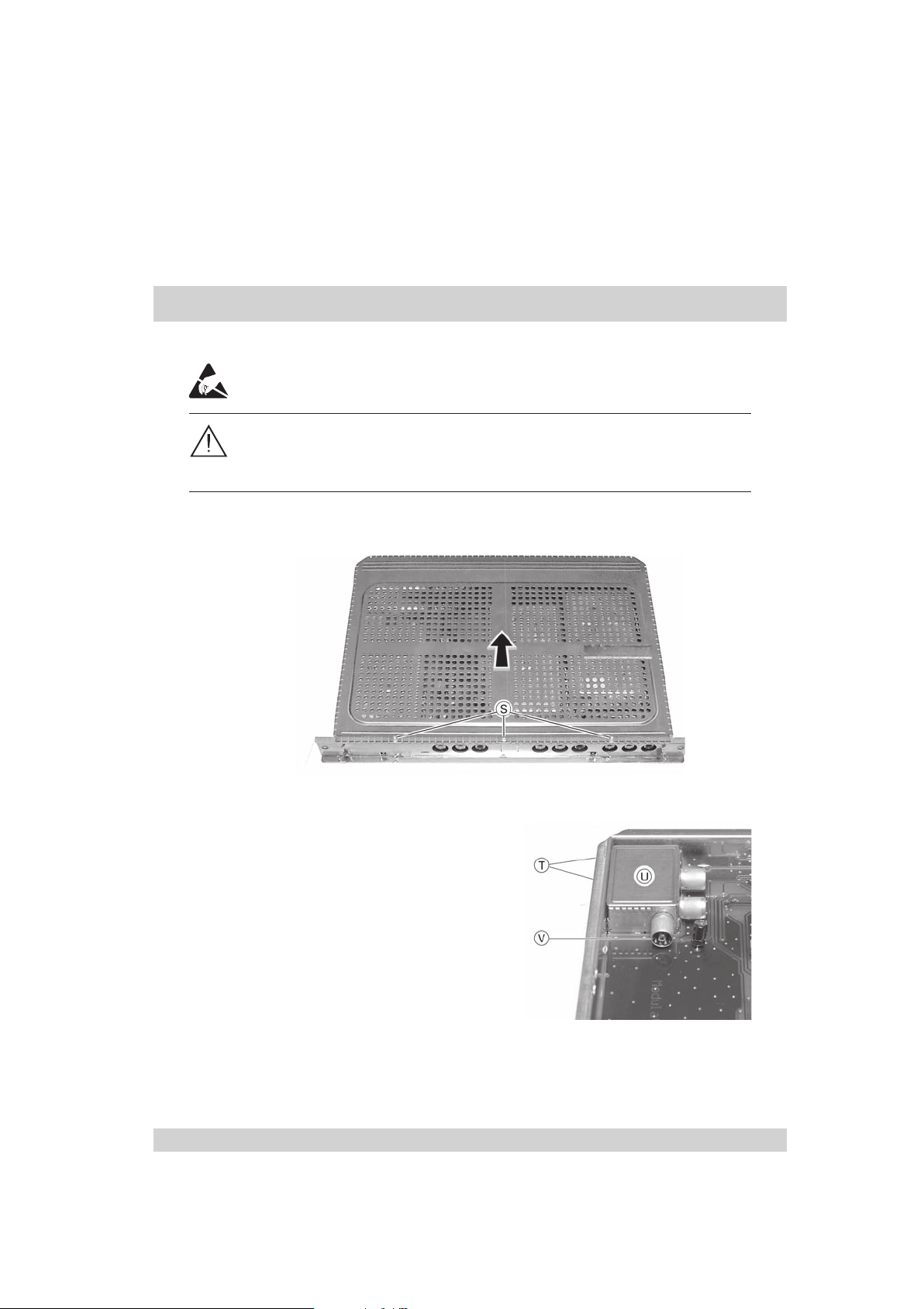
Note
Observe the ESD protective measures!
Danger of cut injuries!
The cassette is made of punched stainless steel parts. Some of them may have
sharp edges.
•
Screw 3 screws S (TORX TX6) out of the cassette cover (Fig. 1).
• Push the cassette cover to the rear and remove it.
Fig. 1
• Screw the fastening screws T out
of the combiner
U (Fig. 2).
• Take the combiner out of the cassette.
Fig. 2
• Plug the HF output of the modulator C onto the HF input
(Fig. 2 / 3)
.
- 6 -
V
of the combiner
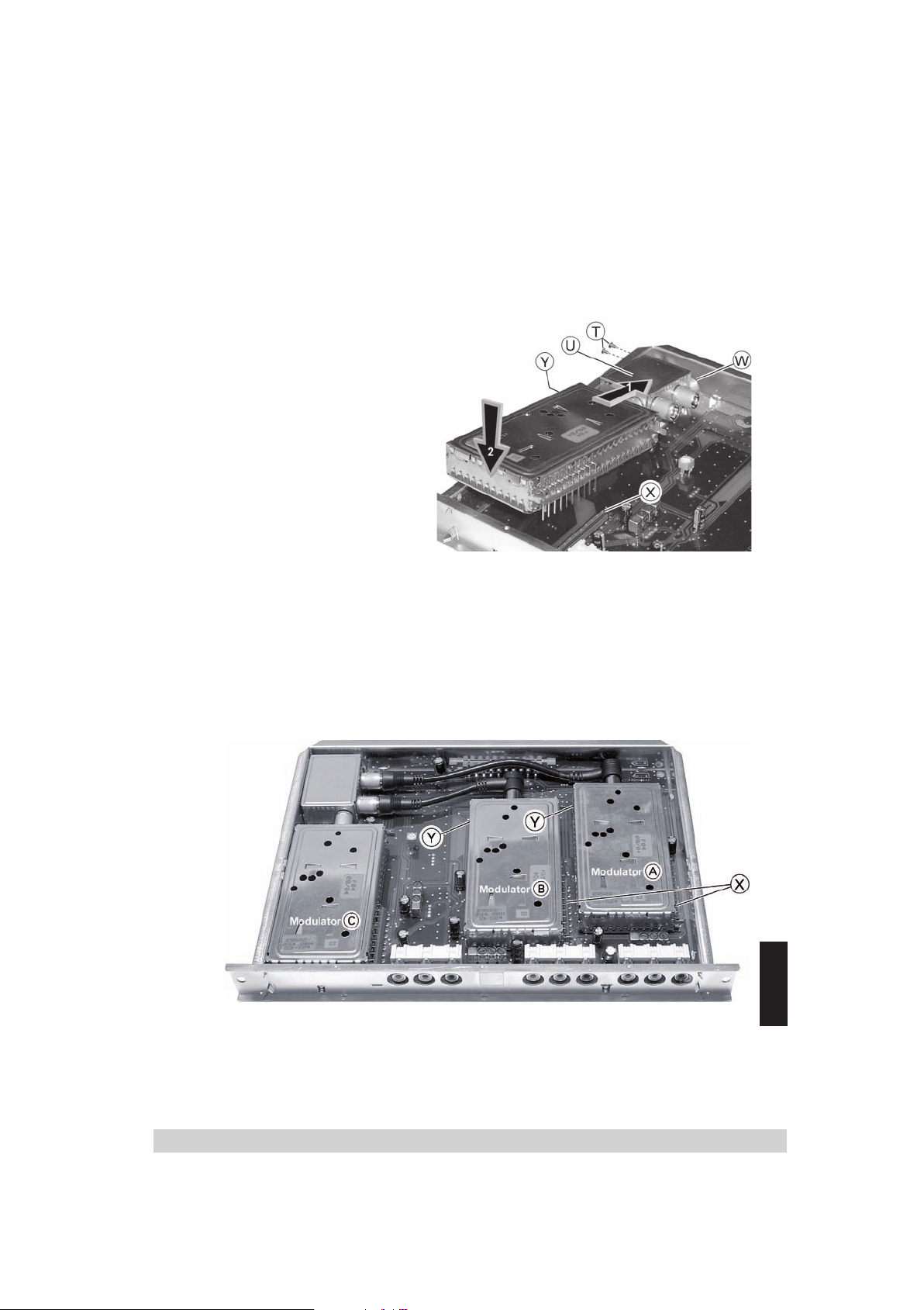
- 7 -
• Insert the HF output of the
combiner U into the opening
W of the cassette frame
and connect the connections of the modulator with
the socket strip
cassette board. Position the
ground connection Y in the
corresponding slot on the
board (Fig. 3). Pull the modulator about 1…2 mm away
from the combiner if necessary.
• Fasten the combiner U with
screws T (Fig. 2/3).
Fig. 3
• Connect the HF output of the respective modulator to the HF input of the com-
biner with the corresponding HF cable.
• Plug the modulators B and A onto the corresponding terminal strips X of
the cassette board as illustrated in Fig. 4. Position the ground connections Y
of the modulators in the respective slots on the board.
X on the
Fig. 4
• Push the cassette cover from the back of the cassette into the guides and fas-
ten it with the 3 screws S (Fig. 1).
- 7 -
ENGLISH

- 8 -
3.2 Installing the cassette in the head end
+24
BREITBA
Caution
Pull the mains plug of the head end out of the mains socket before inserting
or replacing any cassettes.
0
C101
L104
L100
L101
L103
C100
LNC-
+18V
ROT
GRUEN
+18V
Anschl.
0
INPUT OUTPUT OUTPUT INPUT
• Screw the fastening screws S of an unoccupied slot out of the bracket
head end.
• Insert the cassette into the free slot and push it into the housing.
• Align the cassette and apply slight pressure to connect it with the connections
of the circuit board and the HF bus bar.
• Fasten the cassette with the screws S.
3.3 Connecting the cassette
3)/ 3)/3)/
•
Connect the peripheral devices with the cinch input sockets “
low), “
Audio R
•
Connect the head end to the mains power supply.
” R (red) and “
Audio L
” L (white).
Video
of the
” V (yel-
- 8 -

- 9 -
4 The control panel at a glance
4.1 Menu items
Program the cassette using the keys of the control unit of the head end. The
menus appear on the two-line display of the control unit.
You can use the
to select the following menu items:
key
BE–Remote V.34
BE–Remote V.34
please wait . . .
please wait . . .
– Cassettes and modulators
– Switching the modulator on/off
– TV standard
– Channel or frequency input
– Output channel / Output frequency
– Video level
– Audio type
– Audio level
Detailed information on how to use the menu
can be found in the settings described
in the following.
4.2 Control panel
– You can select individual menus and menu items step-by-step using the key-
board of the head end:
menus
is used to scroll forwards through the
.
◀
▶
are used to select parameters from
/
the menus.
are used to set values and initiate
actions.
M is used to save all entries.
– The parameter to be set are underlined (cursor).
– The “Cassette selection” menu is returned to if the key is pressed
longer than two seconds while in any menu. Any entries which have not yet
been saved are reset to the “old” settings.
- 9 -
ENGLISH

- 10 -
5 Programming
Bx 1
..............
..............
..............
+24+24
BREITBABREITBA
5.1 Preparation
• Connect the test receiver to the “TEST OUTPUT”
head end.
• Set the output channel of the
15) and adjust the test receiver to this channel.
• Switch on the modulator if necessary (see page 14).
• Measure the output levels of the installed modulators and ad-
just them to
a uniform output level (see page 13).
5.2 The menus at a glance
installed modulators
1 of the
(see page
L100
L101
L103
C100
LNC-
+18V
ROT
GRUEN
+18V
Anschl.
1
Ein/On
+
◀
–
/
▶
/
BE–Remote
Please wait …
t > 10 s
Bx 1
..............
Bx 2A
3AV STEREO
UHF,BD1,UHF
Bx 2A
Modulator:
MODULAT:
V.3 4
..............
..............
C40
on
Die Displayanzeige ist von der bestückten Cassette abhängig
The displayed data are dependent on the fitted Cassette
Bx 1A
Böx 4
Bx 2B
C5-12,S3-24
C5-12,S3-24
UHF,BD1,UHF
TWIN-SAT
TWIN-SAT
3AV STEREO
C07
C12
C07
Bx 2A
3AV STEREO
M
on / off
LEVEL HF OUT:
0
0 … -7 dB
- 10 -

- 11 -
normal
… -3 dB
Bx 2A
CCIR 5.5
Bx 2A
Channel
Bx 2A
C40
Bx 2A
Lev.:
Bx 2A
Stereo
AUDIO-OUT:
NORM:
FM
OUTPUT:
OUTPUT:
Video:
normal
CCIR …
OIRT
Channel / Frequency
t > 2 s
t > 2 st > 2 s
Stereo / Dual
Bx 2A
▶
▶
C40
Bx 2A
▶
Depth:
Bx 2A
Pic/Snd:
OUTPUT:
Fine 0
MODULAT:
normal
MODULAT:
normal
+63 … -64
normal … -10%
-1 dB … +2 dB
Bx 2A
Vol.:
AUDIO-OUT:
–
M
+
ENGLISH
- 11 -

- 12 -
5.3 Programming the cassette
t > 10 s
Ein/On
BE–Remote
Please wait …
V.3 4
Bx 2A
UHF,BD1,UHF
3AV STEREO
C40
Bx 1A
C5-12,S3-24
TWIN-SAT
C07
Böx 4
C5-12,S3-24
TWIN-SAT
C07
Bx 2B
UHF,BD1,UHF
3AV STEREO
C12
▶
◀
/
+
–
/
Bx 1
..............
..............
..............
Die Displayanzeige ist von der bestückten Cassette abhängig
The displayed data are dependent on the fitted Cassette
• Switch on the head end.
—> The processor reads the cassettes‘ data and switches to slot 1 after
approx. 10 seconds.
—> The software version is displayed (e.g. V.34).
Selecting the cassette
• Select the cassette to be programmed (box no.) by repeat-
edly pressing .
—> The menu
“Bx 2A 3AV STEREO
UHF,BD1,UHF
C40
for example, appears on the display.
“Bx” stands for cassette (box)
“2” for slot 2
“A” for modulator A
“3AV STEREO” indicates the number and audio type
of the installed modulators
”UHF,BD1,UHF” indicates the frequency ranges of the
installed modulators
”C40”
indicates the set output channel
- 12 -
“,

- 13 -
Selecting a modulator
Bx 2A
UHF,BD1,UHF
3AV STEREO
C40
Bx 1A
C5-12,S3-24
TWIN-SAT
C07
Böx 4
C5-12,S3-24
TWIN-SAT
C07
Bx 2B
UHF,BD1,UHF
3AV STEREO
C12
Bx 2A
LEVEL HF OUT:
3AV STEREO
0
M
▶
◀
/
+
–
/
0 … -7 dB
• Use
to select “A”, “B” or “C” as modulator to be
set.
• Press .
—> “3AV STEREO LEVEL HF OUT” e.g. is displayed.
Setting the output level
• If necessary, press to switch to and fro between
the cassette selection menu “Bx 2A 3AV STEREO” and the
output level menu “
lator has the lowest output level
• P
ress
the lowest output level step-by-step from “0
LEVEL HF OUT
” to find out which
.
to adjust the output level of the modulators to
” to “
–7” dB.
• To save the settings, press the M key.
modu-
• Press the key after setting all output levels.
—> “MODULAT: Modulator:” is displayed.
ENGLISH
- 13 -

- 14 -
Switching the modulator on/off
Bx 2A
Modulator:
MODULAT:
on
on / off
Bx 2A
CCIR 5.5
NORM:
FM
CCIR …
OIRT
• Press
to switch the modulator “off” or “on”.
• Press .
—> “NORM: CCIR 5.5 FM”, for example, is displayed.
Setting the TV standard
• Use to set the TV standard:
– CCIR 5.5 FM
– FRANCE 6.5 AM
– CHINA 6.5 FM
– US 4.5 FM
– GB 6.0 FM
– OIRT 6.5 FM
• Press .
—> “OUTPUT: Channel”, for example, is displayed.
- 14 -

- 15 -
Selecting channel / frequency input
Bx 2A
Channel
OUTPUT:
Channel / Frequency
+63 … -64
Bx 2A
C40
OUTPUT:
Fine 0
Bx 2A
C40
OUTPUT:
▶
▶
t > 2 s
• Use
to select channel input (“Channel”) or frequen-
cy input (“Freq.”).
• Press .
—> “OUTPUT: C40”, for example, is displayed.
Setting the output channel / output frequency
• Use to set the output channel or output frequency of
the modulator.
—> The adjustable channel / frequency range depends
on the type of modulator used.
Note on the channel assignment:
You can call up the channel assignment of the modulators
installed in the cassette by repeatably pressing .
You can return to the main menu at the end of the submenu
by pressing . You can interrupt the procedure and
return to the main menu by pressing .
- 15 -
ENGLISH

- 16 -
Setting the frequency offset (fine tuning)
/
Bx 2A
Depth:
MODULAT:
normal
Bx 2A
Lev.:
Video:
normal
normal
… -3 dB
normal … -10%
-1 dB … +2 dB
t > 2 st > 2 s
▶
Bx 2A
Pic/Snd:
MODULAT:
normal
B
A
Dep
M
:
%
-
t > 2 s
A
:
:
Adjust the frequency offset only in individual cases which give
you reason to do so (e. g. Moiré,
interferences), since all TV
sets connected to the cable system have to be fine tuned
after making changes.
• Press
▶
and hold it down until “0” additionally appears
on the display.
• Use to set the offset.
• Press
◀
to return to the channel setting if necessary.
• Press .
—>
“VIDEO:
LEV.:
” appears on the display.
Adjusting the video level
In this menu you can adjust various video output levels of
the installed modulators.
t > 2 s
• Feed in the video signal via cinch input
x 2
th:
x 2
ic/Snd
ODULAT
normal
ODULAT
normal
normal … -10
1 dB … +2 dB
V (yellow)
to “Technical specifications”).
• Use to set the video level (“Normal”, “–1dB”,
“–2dB”, “–3dB”).
(refer
• Keep on pressing
▶
until the “MODULAT: Depth” menu
appears on the display.
- 16 -

- 17 -
Setting the modulation depth (fine tuning)
Bx 2A
Depth:
MODULAT:
normal
Bx 2A
Lev.:
Video:
normal
normal
… -3 dB
normal … -10%
-1 dB … +2 dB
t > 2 st > 2 s
▶
Bx 2A
Pic/Snd:
MODULAT:
normal
A
:
V
:
Lower the modulation depth if the sound drones due to the
picture.
normal
-3 dB
Bx 2
ev.
ideo
normal
• Press
to set the modulation depth (“normal” or
“-5%” or “-10%”).
• Press .
—> The menu
”MODULAT: Pic/Snd:” appears on the display.
Setting the audio carrier amplitude
Lower the amplitude of the audio carrier in the event of
Moiré interferences.
• Use to set the amplitude of the audio carrier
(“–1” dB, ”normal”, “+1” dB, “+2” dB).
• Press
—>
“AUDIO-OUT” appears on the display.
.
ENGLISH
- 17 -

- 18 -
Setting the audio type
Bx 2A
Stereo
AUDIO-OUT:
Stereo / Dual
M
Bx 2A
Vol.:
AUDIO-OUT:
–
+
In this menu you can set the audio type in which the modu-
lator is to modulate the audio signals.
• Use
to set the audio type (stereo, dual).
• Press .
—>
“AUDIO-OUT Vol.” appears on the display.
Setting the audio output level
In this menu you can adjust various audio output levels of
the signal sources.
• Feed in the signal (refer to “Technical specifications”).
• Use to set the audio output level.
Saving settings
• Press
M
.
—> You return to the “Cassette selection” menu A
(page 12).
—>
The “new” settings are saved permanently.
Caution:
—> If
selection” menu – “Bx 2A 3AV STEREO” is returned
to without saving the data.
is pressed instead of M , the “Cassette
Alterations reserved. Technical data E & OE.
- 18 -

- 19 -
Channel and frequency tables
I. Band I / III
C 2
C 3
C 4
S 2
S 3
S 4
S 5
S 6
S 7
S 8
S 9
S 10
C 5
C 6
C 7
C 8
Channel
[MHz]
Channel centre frequency
51.00 48.25
58.00 55.25
65.00 62.25
115.00 112.25
122.00 119.25
129.00 126.25
136.00 133.25
143.00 140.25
150.00 147.25
157.00 154.25
164.00 161.25
171.00 168.25
178.00 175.25
185.00 182.25
192.00 189.25
199.00 196.25
[MHz]
Picture carrier frequency
C 9
C 10
C 11
C 12
S 11
S 12
S 13
S 14
S 15
S 16
S 17
S 18
S 19
S 20
Channel
[MHz]
Channel centre frequency
206.00 203.25
213.00 210.25
220.00 217.25
227.00 224.25
234.00 231.25
241.00 238.25
248.00 245.25
255.00 252.25
262.00 259.25
269.00 266.25
276.00 273.25
283.00 280.25
290.00 287.25
297.00 294.25
[MHz]
Picture carrier frequency
- 19 -
ENGLISH

- 20 -
II. Hyperband
Channel
S 21 306.00 303.25
S 22 314.00 311.25
S 23 322.00 319.25
S 24 330.00 327.25
S 25 338.00 335.25
S 26 346.00 343.25
S 27 354.00 351.25
S 28 362.00 359.25
S 29 370.00 367.25
S 30 378.00 375.25
S 31 386.00 383.25
S 32 394.00 391.25
S 33 402.00 399.25
S 34 410.00 407.25
S 35 418.00 415.25
S 36 426.00 423.25
S 37 434.00 431.25
S 38 442.00 439.25
S 39 450.00 447.25
S 40 458.00 455.25
S 41 466.00 463.25
Channel centre frequency
[MHz]
Picture carrier frequency
[MHz]
- 20 -

- 21 -
III. Band IV / V
Channel
C 21 474.00 471.25
C 22 482.00 479.25
C 23 490.00 487.25
C 24 498.00 495.25
C 25 506.00 503.25
C 26 514.00 511.25
C 27 522.00 519.25
C 28 530.00 527.25
C 29 538.00 535.25
C 30 546.00 543.25
C 31 554.00 551.25
C 32 562.00 559.25
C 33 570.00 567.25
C 34 578.00 575.25
C 35 586.00 583.25
C 36 594.00 591.25
C 37 602.00 599.25
C 38 610.00 607.25
C 39 618.00 615.25
C 40 626.00 623.25
C 41 634.00 631.25
C 42 642.00 639.25
C 43 650.00 647.25
C 44 658.00 655.25
C 45 666.00 663.25
[MHz]
Channel centre frequency
Picture carrier frequency
[MHz]
Channel
C 46 674.00 671.25
C 47 682.00 679.25
C 48 690.00 687.25
C 49 698.00 695.25
C 50 706.00 703.25
C 51 714.00 711.25
C 52 722.00 719.25
C 53 730.00 727.25
C 54 738.00 735.25
C 55 746.00 743.25
C 56 754.00 751.25
C 57 762.00 759.25
C 58 770.00 767.25
C 59 778.00 775.25
C 60 786.00 783.25
C 61 794.00 791.25
C 62 802.00 799.25
C 63 810.00 807.25
C 64 818.00 815.25
C 65 826.00 823.25
C 66 834.00 831.25
C 67 842.00 839.25
C 68 850.00 847.25
C 69 858.00 855.25
[MHz]
Channel centre frequency
Picture carrier frequency
[MHz]
ENGLISH
- 21 -

Alterations reserved. Technical data E. & O.E. 265009412600
© by GSS GmbH 08122005
 Loading...