

HMPT 1000 C
Assembly Instruction

Contents
1 Safety regulations and notes ........................................................................4
2 General information ....................................................................................5
2.1 Packing contents ............................................................................5
2.2 Meaning of the symbols used ..........................................................5
2.3 Technical data ...............................................................................5
2.4 Description ...................................................................................6
Input signal path "INROUTE" ..........................................................7
Menu setting "A=1 B=2" .........................................................7
Menu setting "A+B=1 2=OFF" .................................................7
Output signal path "OUTROUTE" ....................................................8
Menu setting "1=>MA 2=>MB" ...............................................8
Menu setting "1=>ASI MA=OFF" .............................................8
Menu setting "2=>ASI MB=OFF" .............................................8
General ........................................................................................9
2.5 Software query............................................................................10
2.6 How the TPS module works ...........................................................10
Station filter ................................................................................10
Stuffing.......................................................................................10
Changing the NIT ........................................................................10
Changing the operator ID (CAT) ...................................................10
2.7 Explanation of the term "symbol rate" ............................................11
3 Assembly ..................................................................................................12
3.1 Installing the cassette....................................................................12
3.2 EMC regulations ..........................................................................13
3.3 Cassette overview........................................................................14
3.4 Connecting the cassette ................................................................14
3.5 Retrofitting a CA module ..............................................................15
4 The control panel at a glance ..................................................................... 16
4.1 Menu items .................................................................................16
4.2 Control panel ..............................................................................17
5 Programming ............................................................................................ 17
5.1 Preparation .................................................................................17
5.2 Programming procedure ...............................................................18
5.3 Programming the cassette ............................................................22
Selecting the cassette, displaying the software version ......................22
Ethernet parameters .....................................................................23
IP address of the cassette ..............................................................23
Address range ............................................................................24
- 2 - HMPT 1000 C

Address of the gateway ................................................................24
UDP port ....................................................................................24
Input signal path ..........................................................................25
Output signal path .......................................................................25
ASI transfer rate ..........................................................................26
ASI options................................................................................... 26
Channel strip ..............................................................................27
Selecting channel / frequency setting .............................................27
Output frequency, Output channel, Modulator .................................28
Output levels of the channel strips ..................................................29
Input data stream .........................................................................29
IP reception, Transmission protocol, Port number .............................30
IP address of the input transport stream ..........................................31
Station filter ................................................................................31
"INROUTE" menu setting "A = 1 B = 2" ..................................32
Test the status of the individual services: ....................................33
"INROUTE" menu setting "A+B = 1 2 = OFF" ..........................33
QAM modulation, Inverting the user signal .....................................34
Setting the QAM modulation ....................................................34
Inverting the user signal ...........................................................34
Output symbol range ...................................................................35
Substitute signal in the case of an incorrect input signal ...................36
Transport stream / ORGNET-ID .....................................................36
Network Information Table (NIT) ....................................................37
Network/operator identification ....................................................38
Deleting a PID .............................................................................39
Renaming a PID...........................................................................39
Factory reset ...............................................................................40
Saving settings ............................................................................40
Tuner settings ..............................................................................41
LNB oscillator frequency ..........................................................41
Input symbol rate, DVB mode ...................................................41
Input frequency ......................................................................42
Testing the signal to noise ratio .................................................43
Operation with a CA module ........................................................44
PID monitoring .......................................................................44
CA module ............................................................................44
Descrambling services .............................................................46
6 Final procedures ........................................................................................ 47
7 Channel and frequency tables ....................................................................48
- 3 - HMPT 1000 C

1 safety regulations and notes
• Assembly, installation and servicing should be carried out by authorised
electricians.
• Switch off the operating voltage of the system before beginning with assembly or service work or pull out the mains plug.
• Do not perform installation and service work during thunderstorms.
• Install the system so it will not be able to vibrate…
- in a dust-free, dry environment
- in such a manner that it is protected from moisture, fumes, splashing wa-
ter and dampness
- somewhere protected from direct sunlight
- not within the immediate vicinity of heat sources
- in an ambient temperature of 0 °C to +50 °C. In case of the formation of
condensation wait until the system is completely dried.
• Ensure that the head-end station is adequately ventilated. Do not cover the
ventilation slots.
• Beware of short circuits
• No liability is accepted for any damage caused by faulty connections or
inappropriate handling.
• Observe the relevant standards, regulations and guidelines on the installation and operation of antenna systems.
• The standards EN/DIN EN 50083 resp. IEC/EN/DIN EN 60728 must be
observed.
• For further information please read the assembly instructions for the headend station used.
• Test the software versions of the head-end station and the cassette and
update them if necessary. The current software versions can be found at
"www.mygss.eu".
Take action to prevent static discharge when working on the device!
Electronic devices should never be disposed of in the household rubbish. In
accordance with directive 2002/96/EC of the European Parliament and the
European Council from January 27, 2003 which addresses old electronic and
electrical devices, such devices must be disposed of at a designated collection
facility. At the end of its service life, please take your device to one of these
public collection facilities for proper disposal.
- 4 - HMPT 1000 C

2 general information
2.1 PaCk ing Co ntents
1 Cassette HMPT 1000 C
1 RF cable
1 Brief assembly instructions
2.2 meani ng of t h e sym b ols us e d
Important note
—> General note
• Performing works
2.3 teChniCal da ta
The devices meet the following EU directives:
2011/65/EU, 2014/30/EU, 2014/35/EU
The product fulfils the guidelines and standards for CE labelling (page 49).
Unless otherwise noted all values are specified as "typical".
RF input
Frequency range: ....................................................... 925 … 2150 MHz
Level range: ............................................................ 60 dBμV … 80 dBμV
Return loss: ..................................................................................> 8 dB
DVB-S modes: ............................................DVB-S 1/2 , 2/3 , 3/4 , 5/6 , 7/8
DVB-S2 modes: ...................QPSK 1/2 , 3/5 , 2/3 , 3/4 , 4/5 , 5/6 , 8/9 , 9/
8PSK 3/5 , 2/3 , 3/4 , 5/6 , 8/9 , 9/
10
10
Symbol rate DVB-S: .......................................... QPSK: 2 … 45 MSymb/s
Symbol rate DVB-S2: ........................................ QPSK: 10 … 30 MSymb/s
8PSK: 10 … 31 MSymb/s
RF output
Channels: ............................................................................ S21 … C69
Frequency range: ............................................. 42.0 MHz … 860.0 MHz
Output level: ..................................................................... max. 96 dBμV
Output impedance: ......................................................................... 75 Ω
- 5 - HMPT 1000 C

LAN interface
Standard: ............................................................................. 100-BASE-T
Data rate: ............................................................................... ≤ 80 MBit
Protocols: .......................................................... UDP (User Data Protocol),
RTP (Real-Time Transport Protocol)
ASI interface
Standard: .....................................................................DIN EN 50083-9
Format: ..............................................................MPEG ISO IEC 13818-1
User data rate: .................................................................2 … 90 Mbit/s
Level (input / output): ..................................................... 800 mVPP ± 10%
Return loss (input):...............................................> 17 dB (5 … 270 MHz)
Connections
SAT input: ............................................................................... 1 F socket
RF output: ............................................................................ 1 IEC socket
ASI output: ................................................................1 BNC socket, 75 Ω
Connection strip (10-pin): ..................for supply voltages and control circuits
RS 232 socket: ..................................... serial interface for software update
Conditional access:.......................1 (several channels can be descrambled)
2.4 des CriPtion
The cassette is a
modulated according to DVB-S /
"MPTS / QAM"
-converter, which converts services
DVB-S2
standard and the data stream fed via
(stations)
the LAN interface into one or two QAM-modulated cable signals dependent on
the input and output signal paths.
The
cassette
has one SAT IF input and one
RF output. Additionally it is equipped with a LAN interface and an ASI output
(ASI – Asynchronous Serial Interface acc. DIN EN 50083-9).
The transport stream fed via the LAN socket can be inserted into the transport
stream of the receiving stage via the TPS module. The signal path is set in the
menu items input signal path
- 6 - HMPT 1000 C
"INROUTE" and output signal path "OUTROUTE"
.
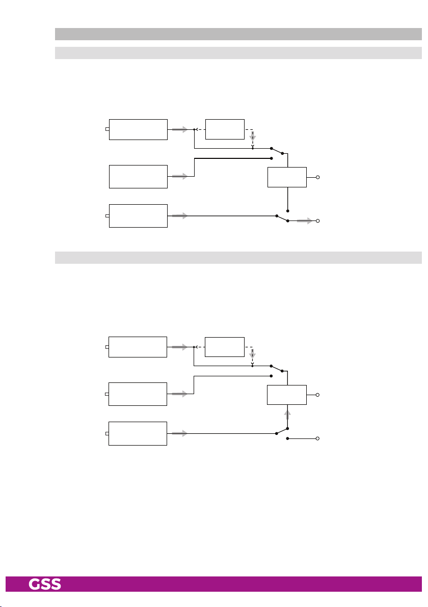
inPut signa l Path "inroute"
menu s et ting "a=1 b=2"
The transport streams of the receiving stage channel strip "A" and of the LAN
input channel strip "A" generate optionally the transport stream 1. The transport stream of the LAN input channel strip "B" generate the transport stream 2.
SAT IF
input ”A“
LAN
interface
LAN
interface
Receiving stage
Channel strip "A"
Channel strip "A"
Channel strip "B"
CA module
TPS
Transport stream 1
Transport stream 2
menu s et ting "a+b=1 2=off"
The transport streams of the receiving stage channel strip "A" and optionally
of the LAN input channel strip "A" generate in conjunction with the transport
stream of the LAN input channel strip "B" the transport stream 1.
The transport
stream 2 is switched off.
SAT IF
input ”A“
Receiving stage
Channel strip "A"
CA module
LAN
interface
LAN
interface
Channel strip "A"
Channel strip "B"
TPS
Transport stream 1
Transport stream 2
- 7 - HMPT 1000 C
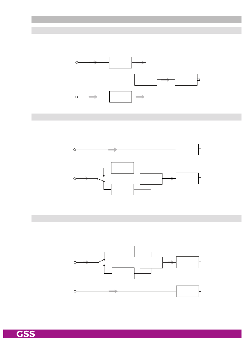
outPu t signal Pa th "outroute"
menu s et ting "1=>ma 2=>mb"
Transport stream 1 is made available via modulator "A", transport stream 2
via modulator "B".
Transport stream 1
Modulator
"A"
Transport stream 2
Combiner
Modulator
"B"
HF output
menu s et ting "1=>asi ma=off"
Transport stream 1 is made available via the ASI output, transport stream 2 via
modulator "B". The signal path via modulator "A" (MA) is switched off.
Transport stream 1
Transport stream 2
Modulator
"A"
Combiner
Modulator
"B"
ASI output
HF output
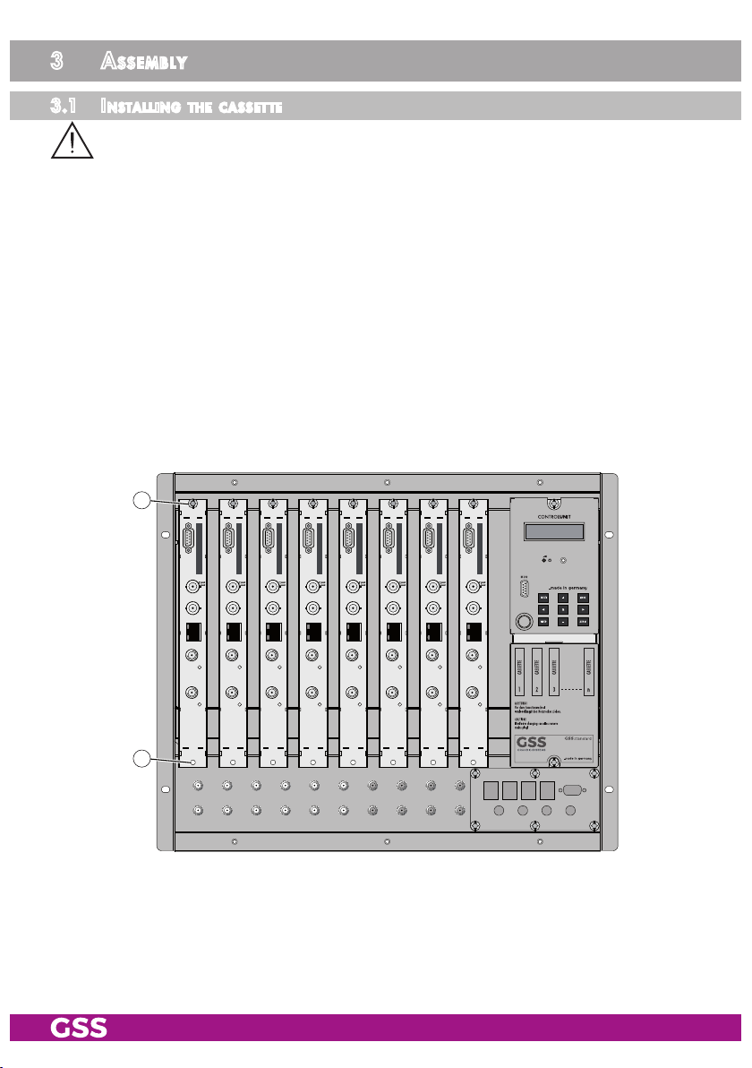
menu s et ting "2=>asi mb=off"
Transport stream 1 is made available via modulator "A", transport stream 2
via the ASI output. The signal path via modulator "B" (MB) is switched off.
Transport stream 1
Modulator
"A"
Modulator
"B"
Combiner
HF output
Transport stream 2
ASI output
- 8 - HMPT 1000 C

general
The cassette is equipped with two channel strips ("A" and "B"). The "A" chan-
nel strip has a digital SAT tuner and can process both the transport stream fed
in via the LAN interface and the transport stream from the SAT tuner.
Using an
appropriate CA module, encoded services coming from the SAT tuner can be
decoded in channel strip"A". The "B" channel strip only processes the transport stream fed in via the LAN interface. The transport streams are directed to
the ASI output or the output converter depending on the set output signal route
"OUTROUTE" via the digital signal processing levels. The RF output signals are
sent through the RF output on the cassette to the output collector. The common
output level of the channel strips can be set in the output collector on the headend station.
An LED in channel strip "A" provides an indication of the signal quality for
the SAT IF input signal and shows whether the modulator of the channel strip
is activated (LED lights up) or deactivated. The quality of the transport stream
being received is also shown in the display ("CN…").
The integrated TPS module (Transport Stream Processing) processes the data
from the transport streams.
The channel strips are indicated in the head-end station display with "Bx …A"
and "Bx …B". The control of the cassette takes place via the control unit of the
head-end station.
When the head-end station is switched on, the two-line LC display shows the
software version of the control unit.
To operate this cassette the software version of the control unit must be "V 45"
or higher. You can find the current operating software for the control unit and
the cassette, the software "BE-Flash" and the current assembly instructions on
the website "www.mygss.eu".
The cassette is intended for use in the
- 9 - HMPT 1000 C
STANDARD LINE
head-end stations.

2.5 soft ware q u ery
Control unit
If necessary, you can activate the indication of the software version of the
control unit manually:
• Press any two keys on the control unit of the head-end station simultaneously
until the display goes dark and the software version, e.g. "V 45" appears.
Cassette
After activating the cassette the software version of the cassette is displayed
(see.page 22).
2.6 how the tPs mod ule wo r ks
After decoding QPSK- or 8PSK-modulated signals, the demodulated data
stream can be accessed via the integrated TPS module. This data stream,
also called transport stream, contains several stations in all their components
(video, audio, data and service information), which can be changed using the
TPS module.
stati on fi lte r
Individual stations can be deleted. This reduces the data rate and, conse-
quently, the output symbol rate required. Additionally stations of the different
transport streams can be assembled to a new transport stream.
stu ffing
The transport stream is padded using what is known as zero data. This ensures
a steady and constant output symbol rate.
Chang in g th e nit
The transport stream contains data in the form of tables which the receiv-
ers evaluate and require for convenient use. The TPS module can adjust the
"Network Information Table" (NIT) to accommodate the new station data. The
"NIT" contains data which is required by the set-top box for the automatic
search feature.
Chang in g th e oPer ator id (Cat)
Some network operators transmit an operator ID in the data stream (e.g.
visAvision). By changing the CAT the operator ID can be adjusted to the demands.
- 10 - HMPT 1000 C

2.7 exP la nat i o n of t h e term "sym bol r ate"
Modulation schemes such as QPSK and QAM transmit multiple bits simultane-
ously. These are referred to as symbols. In addition to the user data flow which
transmits video and audio information, error correction bits are transferred.
The FEC number states the ratio of user bits to the complete transmitted bits.
The output symbol rate is calculated as follows:
256-QAM: SR (A) = FEC x 1/4 x SR (E)
128-QAM: SR (A) = FEC x 2/7 x SR (E)
64-QAM: SR (A) = FEC x 1/3 x SR (E)
32-QAM: SR (A) = FEC x 2/5 x SR (E)
16-QAM: SR (A) = FEC x 1/2 x SR (E)
4-QAM: SR (A) = FEC x 1/1 x SR (E)
Example:
Output symbol rate 64-QAM,
Input symbol rate SR (E) = 27,500
FEC= 3/4,
kSymb/s
SR (A)
SR (A)
= 3/4 x 1/3 x 27,500
=
6,875 kSymb/s
—> If no "FEC" is stated in the station lists, it can be assumed to be
"FEC = 3/4".
kSymb/s
Reception from a transponder with a very low symbol rate (SCPC station)
The extremely low data rate means that the output symbol rate is very low. If
there are reception problems with different digital receivers, set output symbol
rate to a higher value.
Defined symbol rates
Some cable operators specify a fixed symbol rate (e.g. 6,900 kSymb/s).
- 11 - HMPT 1000 C
3 assembly
3.1 installi ng the C assette
– Ensure the head-end station is mounted so it will not be able to vibrate.
Avoid, for example, mounting the head-end station onto a lift shaft or any
other wall or floor construction that vibrates in a similar way.
– Before installing or changing a cassette unplug the power cable from the
mains power socket.
• Remove the fastening screws 1 of an unoccupied slot from the bracket of
the head-end station.
• Insert the cassette in this slot and push it into the housing.
• Align the cassette and apply slight pressure to connect it to the connections
of the board and the RF bus bar.
• Fasten the cassette with the screws 1.
1
1
- 12 - HMPT 1000 C
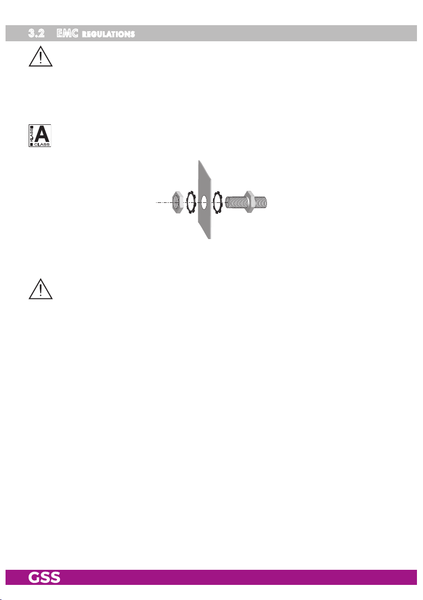
3.2 emC regulations
To comply with the current EMC regulations, it is necessary to connect the lines
leading in and out of the head-end station using cable terminals.
When mounting the cassette in a head-end station which is installed in a 19"
cabinet, make sure the connections leading in and out for the 19" cabinet are
made using cable terminals.
The attenuation of shielding of the connection lines for ASI and antenna must
KLASSE
CLASS
meet the requirements for "Class A".
• Insert the required number of cable terminals in the openings provided in
the head-end station or in the 19" cabinet.
Tighten the nut on the cable terminal until the teeth on the lock washer have penetrated the exterior coating and a good connection is made between the housing
and cable terminal.
- 13 - HMPT 1000 C
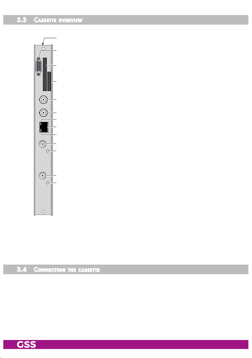
3.3 Cas sette overv iew
#
1 Status LED
2 Not used
@
!
3 Status LED
4 SAT IF input
0
of channel strip "B"
of channel strip "A"
of channel strip "A"
5 Status LED of the LAN interface (data transfer)
6
7 Status LED of the LAN interface (network connection)
8 Not used
9 ASI output
0 Type label
9
8
7
6
5
4
3
LAN socket
! Slot for a CA module
@ D-SUB socket "RS 232"
# MAC address
2
1
The operating software of the cassette can be updated via the 9-pin D-SUB
socket "RS 232" using a PC or notebook and the software "BE-Flash".
You can find the current operating software on the website "www.mygss.eu".
3.4 Con neCting the C a ssette
• Connect the SAT IF input cable to the SAT IF input 4
• Connect the LAN socket 6.
• Connect the ASI output 9 to the peripheral ASI device.
- 14 - HMPT 1000 C
(channel strip "A").
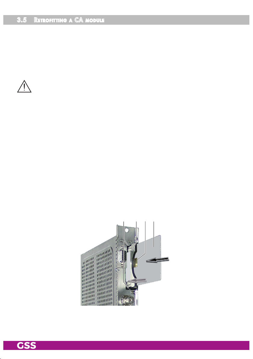
3.5 retr o fitting a Ca module
The cassette is equipped with a common interface. It allows you to connect a
CA module for various scrambling systems and service providers. Scrambled
services (channels) can only be descrambled with a CA module suitable for
the scrambling system and the corresponding smart card. The smart card contains all the information for authorisation, descrambling and subscription.
– Check with the distributor or manufacturer of the CA module to be used
to ensure that it is suitable for descrambling several
– The hardware and software of this cassette have been thoroughly prepared
and tested.
Any changes made by
or even prevent this function.
– When working with the CA module, please read the corresponding operat-
ing manual from the respective provider.
service
providers in the data structures might impair
services
.
• Insert the smart card
smart card faces the thicker side (top) of the CA module.
• Insert the CA module into the guide rails of the CA slot
of the CA module facing the top side of the cassette.
• Push the CA module without canting into the guide rails of the CA slot
and contact it to the common interface.
1
into the CA module
2
so that the chip
3
on the
4 with the top side
34 12
4
- 15 - HMPT 1000 C

4 the Control Panel at a glanCe
4.1 menu i tems
Program the
cassette
using the buttons on the control unit of the head-end sta-
tion. The two-line display of the control unit then shows the menus.
The parameters and functions to be set are underlined.
Use the key to select the following main menu items:
– Setting Ethernet parameters
– Input signal path
– Output signal path
– Channel strip
BE-Re mote V 45
please wai t . . .
– Selecting channel / frequency setting
– Output channel / output frequency
– Output level
– Selecting the input
– IP parameters
– IP address of the input transport stream
– LNB oscillator frequency
– Input symbol rate
– Input frequency
– Station filter
– CA module (if available)
– QAM modulation
– Stuffing
– Substitute signal
– Transport stream / ORGNET-ID
– Network Information Table (NIT)
–
Network/operator identification
– Deleting a PID
– Renaming a PID
– Factory reset
- 16 - HMPT 1000 C

4.2 Con trol Pane l
The key pad on the head-end station is used to scroll through the menus:
scrolls forward through the menus.
select parameters in the menus.
set values, initiate actions.
selects sub-menus.
scrolls backward through the menus.
saves all entries.
5 Programming
5.1 Pre Par atio n
• Test the software versions of the head-end station and the cassette and up-
date them if necessary. The current software versions can be found on the
website "www.mygss.eu".
• Connect the test receiver to the RF output or the test output of the head-end
station.
• Set the output channel / output frequency of the
the TV test receiver to this channel / this frequency.
•
Switch on the channel strip
"A"
(modulator) if necessary (page 28). For the
channel strip, there is a status LED which glows if the channel strip is switched
on.
cassette
(page 28) and adjust
Status LED
Channel strip
"B"
Status LED
Channel strip
"A"
• Balance the output levels of the channel strips "A" and "B" if the difference
in level is ≥ 1 dB (page 29).
- 17 - HMPT 1000 C

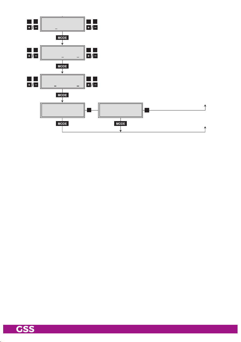
5.2 Progr am ming Pr o Cedure
Ein / On
BE–Remote
please wait …
V 45
Box 4
V 39
LAN-QAM
– – –
Box 1
………
………
………
Bx 1A
C5-12,S3-24
TWIN-SAT
C07
Böx 4
C5-12,S3-24
TWIN-SAT
C07
Box 5
………
………
………
+
t > 10 s
Bx 4
A=1
INROUTE
B=2
A=1 B=2 /
A+B=1 2=OFF
1=>MA 2=>MB
1=>ASI MA=>OFF
2=>ASI MB=>OFF
Bx 4
1=>MA
OUTROUTE
2=>MB
Bx 4
108000 KBits
ASI RATE
188 / 204
positive / negativ
continuous / burst
Bx 4
188 pos. co nt.
ASI OPTION
▶
◀
/
▶
◀
/
Bx 4
stat =>
ETHERNET
Options
stat / DHCP
A
Bx 4
192.168. 0. 1
IP-GATEWAY
Bx 4
255.255.255. 0
IP-MASK
▶
◀
/
Bx 4
192.168. 0. 128
IP-ADDR
▶
◀
/
▶
◀
/
Bx 4
60000
UDP-PORT
▶
◀
/
▶
0 … 65535
Bedienhinweise
"blättert" Menüs vorwärts.
"blättert" Menüs rückwärts.
wählen die Eingabeposition
wählt Untermenü
stellen Werte ein,.
speichert alle Eingaben.
1 zeigt die Eingabeposition
Operating Hints
scrolls forward through the menu.
scrolls backward through the menu.
select the enter position.
selects a submenu.
set values and triggers actions.
saves all entries.
1 shows the enter position
Page 21
- 18 - HMPT 1000 C

Box 1
………
………
………
Bx 1A
C5-12,S3-24
TWIN-SAT
C07
Böx 4
C5-12,S3-24
TWIN-SAT
C07
Box 5
………
………
………
Bx 4A
Freq.
OUTPUT
Channel / Freq.
Bx 4A
850.00 MHz
OUTPUT
on
on / off
S21 … C69
42…860 MHz
▶
◀
/
Bx 4A
-3 dB
LEVEL
0 … -10 dB
Bx 4
Line A <=
LINE
=> Line B
B
1=>MA 2=>MB
1=>ASI MA=>OFF
2=>ASI MB=>OFF
188 / 204
positive / negativ
continuous / burst
Bx 4
188 pos. co nt.
ASI OPTION
▶
◀
/
Bx 4A
Lan
INPUT
Tuner
Line B
Bx 4A
227. 40. 50. 60
IN-IP
▶
◀
/
Bx 4A
on UDP
MODE/PORT
1234
▶
◀
/
on / off
UDP / RTP,
0 … 65535
Bx 4A
Filter
PROGRAM
off
01/07Bx 4A TV +
Das Erste
Services entfernen / hinzufügen
Removing / activating services
nächster Service (Programm)
next service (station)
▶
◀
/
Lan /
Tuner
Lan
Line A / Line B
▶
◀
/
on -> off
M
▶
Bx 4A
27500
SYMBOL
DV B-S
Bx 4A
11836 - 1.8
FREQ
CN 12
▶
◀
/
Bx 4A
10600 MHz
LNB
Anzeige: Signalqualität
Display: Signal quality
▶
◀
/
10600 / 9750
▶
◀
/
DVB-S / QPSK… /
8PSK… / DTV…
27500 / 22000
▶
◀
/
Bx 4A
12.0 dB
C/N
(+ 9.6) OK
Page 21
- 19 - HMPT 1000 C

Box 1
………
………
………
Bx 1A
C5-12,S3-24
TWIN-SAT
C07
Böx 4
C5-12,S3-24
TWIN-SAT
C07
Box 5
………
………
………
Bx 4A
Filter
PROGRAM
off
01/07Bx 4A TV +
Das Erste
Services entfernen / hinzufügen
Removing / activating services
nächster Service (Programm)
next service (station)
▶
◀
/
Bx 4A
SR=6900 (6325)
STUFFING
Bx 4A
Single Carrier
FAILUR E
Bx 4A
256-QAM
QAM
normal
▶
◀
/
▶
◀
/
4 … 256
normal / inverse
Null Packets … Single Carrier
Bx 4A
off
NIT
=> Make
▶
on / off Make
▶
◀
/
Bx 4A
0x0001,0100
TS/ONID
off
▶
◀
/
off / on
on -> off
M
▶
Anzeige: Signalqualität
Display: Signal quality
Bx 4A
12.0 dB
C/N
(+ 9.6) OK
nur Kanalzug “A” mit CA-Modul
only Channel strip “A“ with CA module
Bx 1A
Menu <=
CA
=> Edit
*) Die angezeigte Information ist
abhängig vom verwendeten
CA-Modul.
The information displayed is
dependent on the CA module
used.
Bx 1A 01/03
Information *)
MENU
Bx 1A TV X
. . . .
04/09
X – entschlüsseln
descrambling
0 – nicht entschlüsseln
no descrambling
X / 0
nächster Service
next service
Bx 1A
PID Check
CA
on
on / off
M
▶
◀
▶
◀
/
- 20 - HMPT 1000 C
Box 1
………
………
………
Bx 1A
C5-12,S3-24
TWIN-SAT
C07
Böx 4
C5-12,S3-24
TWIN-SAT
C07
Box 5
………
………
………
Bx 4A
SR=6900 (6325)
STUFFING
Bx 4A
Single Carrier
FAILUR E
Bx 4A
256-QAM
QAM
normal
▶
◀
/
▶
◀
/
4 … 256
normal / inverse
Null Packets … Single Carrier
Bx 4A
off
NIT
=> Make
▶
on / off Make
▶
◀
/
Bx 4A
0x0001,0100
TS/ONID
off
▶
◀
/
off / on
*) Die angezeigte Information ist
abhängig vom verwendeten
CA-Modul.
The information displayed is
dependent on the CA module
used.
Bx 1A 01/03
Information *)
MENU
. . . .
X – entschlüsseln
descrambling
0 – nicht entschlüsseln
no descrambling
nächster Service
next service
M
▶
◀
/
Bx 4A
◀
▶
/
0xDE00
Bx 4A
◀
▶
/
PID 0x0000
Bx 4A
◀
▶
/
0x0000 –> 0000
Bx 4A
Defaults
CAT-ID
off
DROP
off
REMAP
off
FACTORY
=>
◀
▶
/
◀
▶
/
◀
▶
/
▶
on / off
on / off
on / off
Bx 4A
STORE
FACTORY
=> M
auf Werkseinstellung
zurücksetzen und speichern
M
reset to factory defaults
and store
Page 18
A
Page 19
B
- 21 - HMPT 1000 C

5.3 Pro g r a m m i n g the Cass et te
Box 1
………
………
………
Bx 1A
C5-12,S3-24
TWIN-SAT
C07
Böx 4
C5-12,S3-24
TWIN-SAT
C07
Box 5
………
………
………
—> Pressing the button for longer than 2 seconds cancels the
programming procedure. This takes you back to the programme
item "Selecting the cassette" from any menu. Any entries that have
not been saved are reset to the previous settings.
—> Entries in the menus can be saved by pressing the key. You are
taken back to the "Selecting the cassette" menu item.
—> The cursor position for settings is shown by "_".
• Switch on the head-end station
—> The display shows the software version (e.g. V 45)
—> The processor reads the
onds).
cassettes
‘ data (approximately 10 sec-
Ein / On
BE–Remote
please wai t …
V 45
t > 10 s
seleC ting t he Cas s et te, disPl ayin g the s o ft war e vers ion
+
• Select the
Box 4
V 39
cassette
LAN-QAM
– – –
you want to program (e.g. Box 4) by repeatedly pressing
the buttons if necessary.
—> The display shows e.g. the menu
V39
"Box 4" s tands for
"
LAN-QAM
" Type of cassette
"V 39" Software version of the cassette
"Box 4 LAN-QAM"
:
slot
4
• Press the button.
—> The "Ethernet parameters" – "ETHERNET" menu is activated.
- 22 - HMPT 1000 C

ether net Parameter s
In this menu you specify whether the Ethernet parameters for the cassette are
entered automatically by a connected server ("DHCP"), or whether you want
to enter them manually ("stat"). To assign the cassette uniquely, each IPTV cassette must be allocated its own IP address.
Bx 4
stat =>
ETHE RNET
Opti ons
• Press the buttons to select manual setting ("stat") or automatic setting
("DHCP") of the Ethernet parameters.
• Press the
button to activate the setting options
—> The "IP address of the cassette" – menu "IP-ADDR" is activated.
("Options")
.
iP a ddress of th e Cass e t t e
If you choose to enter the Ethernet parameters manually, set the IP address of
the cassette in this menu. If "DHCP" is selected, the "IP-ADDR", "IP-MASK" and
"IP-GATEWAY" sub-menus display the parameters that were assigned automati-
cally by a connected server. If a server is not connected, " 0. 0. 0. 0*"
appears in the corresponding menu. The star " * " in the display means that
the data is provided by a DHCP server.
• Use the
Bx 4
192. 168. 0.128
buttons to place the cursor under the digit of the IP address
IP-A DDR
displayed to be set and use to set the IP address wished.
• Press the
—> The "Address range"
- 23 - HMPT 1000 C
button.
– "IP-MASK" menu is activated.
addres s range
In this menu you define the address range for the cassettes connected to the
LAN network.
• Use the
Bx 4
255. 255.255. 0
buttons to place the cursor under the digit of the IP address
IP-M ASK
displayed to be set and use to set the IP address wished.
• Press the
—> The "Address of the gateway"
button.
– "IP-GATEWAY" menu is activated.
addres s of t he gateway
The address of a gateway (server) can be set in this menu. If no gateway is
used you can skip this setting.
• Use the
Bx 4
192. 168. 0. 1
buttons to place the cursor under the digit of the IP address
IP-G ATEWAY
displayed to be set and use to set the IP address wished.
• Press the
button.
—> The "UDP port"
– "UDP-PORT" menu is activated.
udP P ort
The UDP port setting is required if the cassette needs to be reached externally
to make the setting, such as from another input frequency. This setting is intended for future functions and can be skipped for this cassette.
Bx 4
6000 0
- 24 - HMPT 1000 C
UDP- PORT

• Use the
buttons to place the cursor under the digit of the port number
displayed to be set and use to set the port number wished ("0" …
"65535").
• Press the button.
—> The "Input signal path" – "INROUTE" menu is activated.
inPut signa l Path
In this menu you define the signal path of the input transport streams.
Menu setting "A = 1 B = 2" (page 7).
Menu setting "A+B = 1 2 = OFF" (page 7).
Bx 4
A=1
INRO UTE
B=2
• Use the buttons to select the signal path wished.
• Press the button.
—> The "Output signal path" – "OUTROUTE" menu is activated.
outPu t signal Pa th
In this menu you define the signal path of the output transport streams.
Menu setting "1 => MA 2 => MB" (page 8).
Menu setting "1 => ASI MA => OFF" (page 8).
Menu setting "2 => ASI MB => OFF" (page 8).
Bx 4
1=>M A
OUTR OUTE
2=>M B
• Use the buttons to select the signal path wished.
• If you do not want to do ASI settings, press the button.
—> The "Channel strip" – "LINE" menu is activated
- 25 - HMPT 1000 C
(page 27).

• Press the button.
—> The "ASI transfer rate" – "ASI RATE" menu is activated.
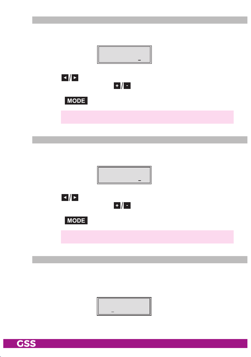
asi t r a nsfer r ate
In this menu you set the transfer rate for the ASI component connected.
For this setting please take the required information from the documentation
(technical data) of the ASI component to be connected.
Bx 4
1080 00 KBits
ASI RATE
• Use the buttons to place the cursor under the digits to be set for the
transfer rate then use the buttons to set the transfer rate wished.
• Press the button.
—> The "ASI options" – "ASI OPTION" menu is activated.
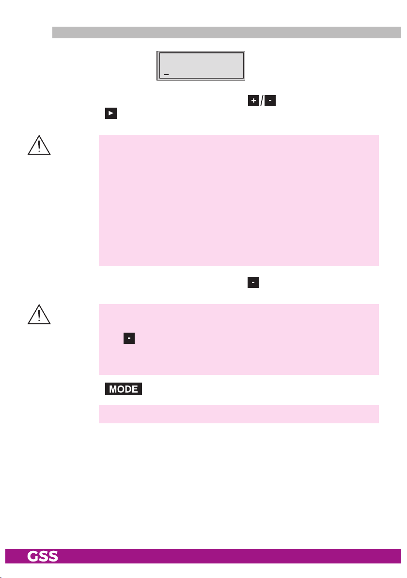
asi oPtions
In this menu you define the size of the data packets, their polarity and the type
of transmission.
For this setting please take the required information from the documentation
(technical data) of the ASI component to be connected.
Bx 4
188 pos. cont.
ASI OPTION
• Press the buttons to set the size of the data packets ("188" or "204"
bits).
• If the polarity of the data to be transmitted has to be changed, press the
buttons
to place the cursor under "pos." (positive – standard) and
using the buttons set to "neg." (negative).
- 26 - HMPT 1000 C

• To change the type of transmission press the
cursor under "cont." (continuous – standard) and using the set to
"burst".
—> Setting "cont."
The data packets of the user data are collected to a great data
packet in the transport stream.
—> Setting "burst"
The data packets of the user data are spaced out evenly in the trans-
port stream.
• Press the button.
—> The "Channel strip" – "LINE" menu is activated.
Chann el str iP
buttons to
position the
• By pressing
("Line B") by pressing the
—> The "Selecting channel / frequency setting" – "OUTPUT" menu is
Bx 4
Line A <=
select channel strip "A" ("Line A") or select channel strip "B"
button
activated.
LINE
=> L ine B
.
seleC ting C hannel / freq uenCy s et ting
In this menu, you can choose the channel or frequen cy setting for the adjust-
ment of the RF output. The channel setting covers the range of channels S21 …
C69, the frequency setting covers the range from 42.0 MHz to 860.0 MHz.
The QAM signal is normally transmitted with a bandwidth of 8 MHz. This
means that you can only use the channel centre frequency of the existing
channel grid in the range of channels S21 … C69 (frequency grid 8 MHz).
The CCIR channel grid is 7 MHz in the range of the lower frequency bands
(channels C2 … S20). Therefore the frequency setting is used here. If one uses
the existing channel grid of 7 MHz in these channel ranges, this will result in
- 27 - HMPT 1000 C

interference (overlapping) with the 8 MHz QAM signal packages, thus causing transmission problems.
For programming in these channel ranges and in the frequency ranges below
them, we recommend starting with channel S21 / 306 MHz going back in
steps of 8 MHz (see frequency table on page 48), or reducing the bandwidth of
the QAM output signal by removing stations.
Bx 4 A
Chan nel
OUTP UT
• Use to select channel setting "Channel" or frequency setting "Freq.".
• Press the button.
—> The "Output channel" or "Output frequency" – "OUTPUT" menu is
activated.
outPu t freq uenCy, ou t Put C h a nnel, mo dulat o r
In this menu, dependent on the setting before, you set
(42.0 … 860.0 MHz) or
the output channel (S21 … C69) of the channel strip.
the output frequency
Additionally the modulator of the channel strip can be switched off or on.
• Use the
Bx 4A
850.00
OUTPUT
on
or
Bx 4 A
S21
buttons to position the cursor under the digit to be set for
OUTP UT
on
the frequency or channel display then use to set the desired output
frequency or channel.
• To switch off the modulator place the cursor under "on" using the button
and switch "off" the modulator of the channel strip using the buttons.
—>
The switched off modulator is indicated by " - - - " in the display.
• If the modulator is switched "off" use the to switch it "on".
• Press the button.
—>
The "Output levels of the channel strips" – "LEVEL" menu is activated.
- 28 - HMPT 1000 C

outPu t level s of t he Cha nn el st riPs
This menu item is used to set the output levels of the modulators of the channel
strips "A" and "B" to the same value.
Bx 4 A
0 dB
LEVE L
• Measure and note down the output level of the channel strip.
• By repeatedly pressing the button scroll back to the "Selecting the
channel strip" menu.
• Select the other channel strip
(page 27) and set the following menu items:
• "Selecting channel / frequency setting", page 27.
• "Setting the output channel" or "Setting the output frequency", page 28.
• Switch on the modulator if necessary, page 28.
• Measure and note down the output level.
• Activate the
• By pressi
the lower output level of the other channel strip incrementally from "0
"
–10 dB".
"LEVEL" menu of the channel strip with the higher output level.
ng adjust the higher output level of one channel strip to
" to
• Press the button.
—> Channel strip "A":
The "Selecting the input data stream" – "
—> Channel strip "B":
The "Switching the IP address off or on, selecting the transmission
protocol, setting the port number" – "
vated (page 29).
INPUT
" menu is activated.
MODE / PORT
" menu is acti-
inPut data s tream
In this menu you select the signal source for the selection of the services. The
transport streams to be processed are provided by the tuner of channel strip
"A" and the LAN interface "Lan".
Bx 4 A
Lan
- 29 - HMPT 1000 C
INPU T

• Press the buttons to select the signal source of the input transport
stream ("Lan", "Tuner").
• Press the button.
—> Setting "Lan":
The "IP reception, Transmission protocol, Port number" – "MODE /
PORT" menu is activated.
—> Setting "Tuner":
The "LNB oscillator frequency" – "LNB" menu is activated. Continue
with chapter "Tuner settings", page 41.
iP r eCePtio n, transm ission P roto C ol, Port n umber
In this menu you can switch off or on the IP address of the transport stream fed
via the LAN interface and define the transmission protocol and the port number.
These settings are not necessary in the channel strip "B" if "A+B=1 2=OFF" is
set in the "INROUTE" menu.
Bx 4 A
on UDP
MODE /PORT
12 34
Switching the IP address off or on
• Press the
buttons to switch "
off" or "on
" the IP address of the trans-
port stream fed via the LAN interface, if necessary.
Selecting the transmission protocol
• Press the button to position the cursor under "UDP" or "RTP".
• Using the buttons to select the transmission protocol wished:
"UDP" – The User Datagram Protocol is for the connectionless transmission of
data to a certain application. The port number of the service is also
sent which the data should obtain.
"RTP" – The Real-time Transport Protocol is for continuously transmitting mul-
timedia data streams in an IP network. Unlike UDP, the header is
transmitted which makes the data transmission more robust.
Setting the port number
• Press the button to position the cursor under the port number e.g.
" 1234".
• Use the buttons to position the cursor under the digit of the port
number displayed to be set.
- 30 - HMPT 1000 C

• Using the buttons set the port number wished.
• Press the button.
—> The "IP address of the input transport stream" – "IN-IP" menu is
activated.
iP a ddress o f the inPut transPor t stre am
In this menu you can set the IP address of the transport stream fed via the LAN
interface.
Bx 4 A
227. 40. 50. 60
IN-I P
• Use the buttons to position the cursor under the digit of the IP address displayed to be set.
• Using the buttons set the IP address wished.
• Press the button.
—> The "Station filter" – "PROGRAM" menu is activated.
stati on fi lte r
The default setting for the station filter is "off". In this menu you define the
services received to be transmitted. If services are activated the output symbol
rate increases.
If the station filter is switched off (factory default) all services of the transport
stream passes the station filter. As soon as the station filter is activated all services are inactive and can be added to the transport stream selectively.
Bx 4 A
Filt er
PROG RAM
off
M
▶
Das Erste
01/0 7Bx 4 A TV +
The figures of the menus below are dependent on the setting of the "Input
signal path" menu (page 25).
- 31 - HMPT 1000 C

"inroute" menu settin g "a = 1 b = 2"
•
Press the
—> All services from the channel strip will be read, and then displayed
—> If no service is found, the following message will appear in the dis-
In this case, check the configuration of the antenna system and the
—> The display shows e.g.:
Meaning of the indicators in the example:
"Bx 4A" Slot 4, channel strip "A"
"TV" "Television" (type of service)
" + " The currently selected service is activated.
"
"
"RA" "Radio" (type of service)
For radio stations, the back
" – "
" * " A star means that the service selected is encoded. To
button.
with name and type of the service.
play: "FILTER no Service".
head-end station, as well as the previously adjusted settings for the
cassette and the components connected to the LAN input.
01/0 7Bx 4 A TV +
Das Erste
01/07" The 1st of 7 services is being displayed.
Das Erste
Further possible terms displayed:
" Name of the service
ground of the screen of the
connected TV or test receiver is darkened.
The currently selected service is
enable the service, the CA module and the appropriate smart card of the provider are required.
switched off.
—> If a service number (e.g. "131") appears instead of "TV" or "RA",
this indicates that an unnamed service or an undefined data stream
is being received.
• Use the
- 32 - HMPT 1000 C
to activate (indicated by " + ") or to remove them (indicated by " – ").
buttons to call up the services in sequential order, then use
—> Pressing the button all services can be activated or deac-
tivated.

•
Press the button.
—>
The filter is activated.
The display shows "PROGRAM Filter on".
—> If
services
are activated the corresponding PIDs (audio, video, text)
are inserted into the transport stream and the PAT and SDT tables
are updated.
te st th e status of th e indiv idual serv iCes:
• If the filter is switched on, press the
button. In this mode you can test the
settings of the station filter again or change them if necessary.
• In the "PROGRAM Filter on" menu the station filter switched on can be
switched "off" using the buttons if necessary.
"inroute" menu settin g "a+b = 1 2 = off"
Bx 4 A
Filt er
PROG RAM
off
01/0 7Bx 4 A TV +
Das Erste
02/0 9Bx 4 B TV +
…………
▶
Bx 4 A
Filt er
PROG RAM
on
◀
/
◀
/
on / off
▶
▶
• Set the channel strip "A" or "B".
—> The setting of the station filters for the channel strips "A" and "B" is
identical and follows the description above.
- 33 - HMPT 1000 C

• Press the button.
—
> The "QAM modulation, inverting the user signal"
activated.
Programming the channel strip "A" with a CA module installed the
"PID monitoring" – "CA"
menu
is activated
qam modu lation, inve rting t h e use r sign al
– "QAM" menu is
(page 44).
In this menu, you can set the QAM modulation and
for exceptional cases and
"older" digital cable receivers invert the spectral position of the user signal
"inverse"
.
Bx 4 A
64- QAM
QAM
norm al
setting the qa m modulat i o n
•
Use to set the QAM modulation ("4" … "256").
—> For higher QAM modulation, the output symbol rate is lowered.
An output QAM modulation of >64QAM places a large burden
on the cable network. Due to noise, delay and frequency response
problems, reception of the converted output signal can be impeded.
invert i n g the user s ignal
• Use the buttons to place the cursor under "normal".
• Use to set the spectral position to "inverse".
• Press the button.
—> The "Output symbol rate" – "STUFFING" menu is activated.
- 34 - HMPT 1000 C

outPu t sym bol r an g e
In this menu, you can modify the output symbol rate.
Bx 4A
SR=6900 (6325)
Zahl 1 Zahl 2
STUFFING
SR=6900 (= "Number 1"): Active output symbol rate
(6325) (= "Number 2"): The current measured output symbol rate.
If the station filter is activated, this value is lower than the value of the
"Number 1". The value fluctuates, since the data rates of individual services
are dynamically modified by the broadcasters.
•
Use the buttons to place the cursor under the number to be changed
("Number 1") and set the symbol rate with the buttons . The value
set corresponds to the new output symbol rate.
Increasing the value of "Number 1".
—> The "Number 1" can be increased to any value up to 7500.
—> Using values > 6950 you exceed the bandwidth of a 8 MHz fre-
quency grid.
Reducing the value of "Number 1".
—>
With the station filter switched "on", the "Number 1" can be decreased. To do this, observe the "Number2" for approx. 30 seconds
and note the highest value. Add roughly 10 % to this value. Do not
decrease the "Number 1" lower than the value of "Number 2".
Is the "Number 1" lower than "Number 2" question marks "??" ap-
pear in the display.
Bx 4A
SR=6500 (6650) ??
STUFFING
• Press the button.
—> The "Substitute signal in the case of an incorrect input signal" –
"FAILURE" menu is activated.
- 35 - HMPT 1000 C

subst itute signal i n the C a se of a n inCo rreCt inPut s ignal
You use this menu to set whether a QAM signal filled with "Null Packets", a
QAM signal filled with null packets and self-made tables "Tables" or a "Single
Carrier" signal should be provided as an output signal whenever an incorrect
input signal occurs. Self-made tables are transmitted furthermore.
Bx 4 A
Null Packets
FAILUR E
• Use the buttons to set the output signal required.
• Press the button.
—>
The "Transport stream/ORGNET-ID" – "TS/ONID" menu is activated.
tr ansPort stre am / orgnet-id
If the stations of a transponder are split into the transport streams of the chan-
nel strips "A" and "B", one of the both transport streams a new identification
must be allocated to realise the channel search of the settop boxes connected
without mistakes.
If the ORGNET-ID is changed a new NIT must be generated (page 37).
Bx 4 A
0x00 01,0100
TS/O NID
off
• Use the buttons to position the cursor under the digit of the hexadecimal number to be set.
•
Press to set the respective digit of the hexadecimal number.
• Repeat the procedure by the quantity of the digits to be set.
• Using the button place the cursor under "off" and switch "on" the transmitter identification using the buttons.
—>
By pressing the
setting
.
button you return to the hexadecimal number
• Press the button.
—> The "Network Information Table" – "NIT" menu is activated.
- 36 - HMPT 1000 C
networ k info rm ati on table (nit)
Bx 4 A
off
NIT
=> Make
• To switch NIT on/off ("on"/"off") press the buttons.
• Press the button to activate NIT "Make".
—> All active cassettes which are able to output a NIT ("NIT cassettes")
must be set and ready for reception.
—> The NITs of all "NIT cassettes" are switched on.
—> The cassette fetches all the information (output frequencies, output
data rates, etc.) it needs from all the "NIT cassettes" in order to
generate the NIT. This process may take a few seconds.
Then the NIT is generated, added and sent to all "NIT cassettes".
The other "NIT cassettes" also add this new NIT. The status of all
"NIT cassettes" in the NIT menu changes to "on".
The display shows: "read … / copy …".
• To switch off the new NIT
—>
The NITs of the other "NIT c
the NIT of the cassette is
button, the previously generated NIT is added again. If you have
changed parameters in the meantime, you must first select "
to generate a new, up-to-date NIT.
("off")
press the
assettes"
button.
will
stay switched on. When
switched on again ("on") by pressing the
Make
"
• Press the button.
—>
The "Network/Operator identification" – "CAT-ID" menu is activated.
- 37 - HMPT 1000 C

networ k/oPe r ato r iden tifiCation
In this menu, you can change the network/operator identification (CAT-ID –
Conditional Access Table - Identification), for example of the visAvision transponder (Eutelsat 8° West).
Bx 4 A
0xDE 00
CAT-ID
off
CAT is not to be changed.
• Press the button.
—> The "Deleting a PID" – "DROP" menu is activated (page 39).
CAT is to be changed.
The network operator e.g. requires that you set the operator ID of the visAvision
transponder to "2".
•
• Use
Use the
to change
buttons to position the cursor under the digit to be set.
the operator ID from "0xDE00" to "0xDE02".
• Use the button to position the cursor under "off," then use to
activate the new CAT "on".
—> The menu display switches to "modified".
—> If you try to change the network/operator identification (operator
ID) of a transponder which cannot be modified, "not modified" appears in the display.
• Press the button.
—> The "Deleting a PID" – "DROP" menu is activated.
- 38 - HMPT 1000 C

deleti ng a Pid
In this menu a PID of the transport stream can be deleted.
Bx 4 A
PID 0x0000
DROP
off
• Use the buttons to place the cursor under the respective digit of the
hexadecimal number of the PID to be deleted ("0x0000") and set the hexadecimal number using .
• Use
to set the cursor to "
off
" and switch to "on"
(delete)
using the
buttons.
• Press the button.
—> The "Renaming a PID" – "REMAP" menu is activated.
renaming a Pid
In this menu you can allocate a new address to a PID retaining the complete
data content.
Bx 4 A
0x00 00 –> 0000
REMA P
off
• Use the buttons to place the cursor under the respective digit of
the hexadecimal number of the PID to be changed ("0x0000") and set the
hexadecimal number using .
• Use the buttons to place the cursor under the respective digit of the
hexadecimal number of the new PID ("–> 0000").
• Set the hexadecimal number using .
• Use to set the cursor to "off" and switch to "on" (rename) using the
buttons.
• Press the button.
—> The "Factory reset" – "FACTORY Defaults" menu is activated.
- 39 - HMPT 1000 C

faCto ry r e set
In this menu you can reset all settings to the factory defaults.
Bx 4A
Defaults
FACTORY
• Press the button.
—> The factory defaults are invoked ("FACTORY STORE")
—> By pressing the button, you will be returned to the menu
item "Channel strip" without
• Press the button.
—> The factory defaults are saved
—> Back to "Selecting the cassette" (page 22).
—> By pressing the button, you will be returned to the menu
item "Channel strip" without
—> If necessary set channel strip "B".
saving s et tings
• Press the button.
—> The settings are saved.
—>
You will be returned to the menu item "Selecting the cassette" (page 22).
—> If functions of the TPS module are activated, their status is shown in
the second line of the display:
"M" – Station filter is switched on.
"N" – NIT is activated.
"C" – Network/operator identification CAT is activated.
—> If necessary set channel strip "B".
=>
Å
Bx 4A
STORE
FACTORY
=> M
M
invoking the factory defaults
. The display shows "STORE"
saving the factory defaults
.
(page 27).
(page 27).
- 40 - HMPT 1000 C

tu ner se ttings
lnb o sCillat o r fr equenCy
Set the oscillator frequency of the LNB used in this menu.
Bx 4 A
1060 0 MHz
LNB
• Using the button the oscillator frequencies "10600" or "9750" can
be selected directly.
• To set other LNB oscillator frequencies use the buttons to place the
cursor under the digit of the LNB oscillator frequency displayed to be set.
• Press to enter the respective digit of the oscillator frequency of the
LNB used.
• Repeat the procedure by the quantity of the digits to be set.
• Press the button.
—> The "Input symbol rate, DVB mode" – "SYMBOL" menu is activated.
inPut sym b o l rat e, dvb m o d e
The symbol rates of the satellite transponders can be found in the current chan-
nel table of the satellite operator, in various satellite magazines and in the
Internet.
The cassette recognizes the transmitted DVB mode and switches over between
the normal QPSK mode (DVB-S) and the DVB-S2 mode. Receiving stations
with DVB-S2 mode, we suggest to preset the DVB mode to shorten the time for
searching stations.
Bx 4 A
2750 0
DVB-S
SYMB OL
Setting the input symbol rate
• Using the button the symbol rates 27500" or "22000" can be
selected directly.
• To set other symbol rates use the buttons to position the cursor under
the digit of the symbol rate displayed to be set.
• Press
to enter the respective digit of the symbol rate needed.
• Repeat the procedure by the quantity of the digits to be set.
- 41 - HMPT 1000 C

Setting the DVB mode
• Use the button to place the cursor under "DVB-S" and set the required
DVB-S2-mode with the buttons
.
• Press the button.
—> The "Input frequency" – "FREQ" menu is activated.
inPut freq u e n Cy
If three dots " … " appear in the second line of the display, the cassette is in
the "station search" mode. Please wait until the process has finished.
Once the RF receiver has synchronised to the input signal, any offset to the
target frequency is displayed in MHz, e.g. "– 1.8" in the middle of the second
line of the display.
If a question mark "?" appears in the second line of the display, there is no
input signal present. Check the configuration of the antenna system and headend station as well as the preceding settings of the cassette.
Bx 4 A
11836 -1.8
FREQ
CN 1 2
• Use to position the cursor under the digit to be set of the frequency
displayed.
• Press
• Set the frequency offset shown in the display
1MHz
to set the input frequency.
(e.g. "– 1.8")
by varying the input frequency
—> The "CN 12" display e.g., indicates the signal to noise ratio of the
signal received.
using the
to less than
buttons.
• Press the button.
—> The "Signal to noise ratio" – "C/N" menu is activated.
- 42 - HMPT 1000 C

te sting t h e signa l to noise r at io
5
6
7
8
9
!
@
0
#
In this menu you can estimate the quality of the input signal.
Bx 4A
12.0 dB
1 2 3
C/N
(+ 9.6) OK
1 Current signal to noise ratio
2 This value shows the difference between the quality of the input signal
and the threshold of the tuner at this type of modulation.
At a value lower than "5" picture dropouts can occur.
3 If "OK" is shown, the signal to noise ratio is ok.
If a value < 5 is shown under 2 the display changes from "OK" to "??".
In this case check the input signal.
—>
In addition to the indicator in the display, there is also a status LED
which indicates the quality of the received transport stream.
4
3
2
1
3 Status-LED Tuner A
LED indicator Indication
Green Signal quality is good
Yellow
Red No signal
Off
Signal quality is insufficient
The channel strip (modulator)
is switched off
• Press the button
• Press the button.
to return to the main menu.
—> The "Station filter" – "PROGRAM" menu is activated.
Continue with the programming procedure as described from page 31 on.
- 43 - HMPT 1000 C

oPerat i on wit h a Ca module
In order for this function of the CA module to be possible, stations / services
capable of being descrambled by the CA module and the smart card you are
using must be selected in the "Station filter" – "PROGRAM" menu of channel
strip "A" (page 31).
Where both scrambled and unscrambled services are transmitted via a single
channel, short-term picture loss may occur when switching between scrambled
and unscrambled services.
Pid m o nitor ing
The factory default of the PID monitoring is switched on. If particular PIDs are
not descrambled the CI module is reset. Additionally dropouts may occur if
several services are descrambled. To prevent this the PID monitoring can be
switched off.
Bx 4A
PID Check
CA
on
• Use the buttons to switch "off" or "on". the PID monitoring.
• Press the button.
—>
The "CA module" – "CA" menu is activated.
Ca mo dule
The menu varies according to which CA module you are using. For this rea-
son, please refer to the operating manual of your particular CA module. The
relevant information is shown in the display of the head-end station. This may
appear as a fixed display or as scrolling text according to display capabilities.
Bx 4A
Menu <=
—> By pressing the button you can skip the "Configuring the
CA module" – "CA" menu and activate the "QAM modulation" –
"QAM" menu (page 34).
• Press the
- 44 - HMPT 1000 C
button to activate the menu of the CA module.
CA
=> Edit

M
Bx4
X
.
04/09
Bx 4A 01/03
Information *)
MENU
Bx 4A
Menu <=
Ï
CA
=> Edit
Å
Bx 4A TV X
A TV
. . . .
. . .
04/09
—> The display shows e.g.: Bx 4A 01/03 MENU
Information
Meaning of the indicators:
"Bx 4A" Slot 4, channel strip "A"
"
01/03
" The first of three menu items is activated.
"
MENU
" The menu of the CA module is activated.
For the explanation of further details please use the operating instructions of
the CA module used.
• Use the buttons to activate the menu desired.
• Press the button to activate the menu.
• Use the buttons to select the function desired.
• To set the CA module use the and buttons.
• All settings are saved by pressing the button.
—> You will be returned to the "CA module" – "CA" menu item.
—>
By pressing the button you can cancel the settings in the
menu of the CA module and are returned to the "CA module" – "CA"
menu.
• Press the button.
—> The "Descrambling services" – "Edit" menu is activated.
- 45 - HMPT 1000 C

desCr am bling s e rviCes
0
/03
)
In this menu you select the services wished from the scrambled data stream,
which are to be descrambled.
Bx 4A 01/03
x 4A
Information *)
Information *
• Use the
to be descrambled, then use
ble them ("0").
Bx 4A
Menu <=
Ï
M
MENU
—> The display shows e.g.:
. . . .
CA
=> Edit
Å
Bx 4A TV X
. . . .
Bx 4A TV X 04/09
Meaning of the indicators in the example:
"Bx 4A" Slot 4, channel strip "A"
"TV" "Television" (type of service)
"X" Descrambling is set for
"
04/09" The 4th of 9 services is being displayed.
"
. . . .
" Name of the service
Further possible terms displayed:
"RA" "Radio" (type of service)
"0"
The currently selected service
buttons to call up the services in sequential order which are
to descramble ("X") or not to descram-
the currently
remains unchanged.
04/09
selected
station.
•
Press the button to save changes and activate the filter.
—> The filter is activated. The display shows the "CA module" – "CA"
menu.
Bx 4A
Menu <=
CA
=> Edit
• Press the button.
—> The "QAM modulation" – "QAM" menu is activated (page 34).
- 46 - HMPT 1000 C

6 fi n a l ProCedures
After installing the head-end station, upgrading accessories or installing cas-
settes it is necessary to tighten all cable connections, cable terminals and cover
screws in order to maintain compliance with current EMC regulations securely.
• Securely tighten the cable bolted connections fingertight using an appropriate open-ended spanner.
• Measure the output levels of the other cassettes and tune them to a uniform
output level using the appropriate level controls or software dependent on
the head-end station used. Please regard the assembly instructions of the
respective head-end station.
—>
In order to prevent interference within the head-end station and the
cable system, the output levels of the digital cassettes must be set
lower by 8dB compared to analogue cassettes.
• Mount the front cover (see assembly instructions of the head-end station).
- 47 - HMPT 1000 C

7 Channel and frequenCy tables
Advice for a frequency grid (8 MHz) in the Band I/III
]
[MHz
Frequenzraster
Frequency grid
42.00
50.00
58.00
66.00
74.00
]
[MHz
Frequenzraster
Frequency grid
82.00
114.00
122.00
130.00
138.00
]
[MHz
Frequenzraster
Frequency grid
146.00
154.00
162.00
170.00
178.00
Frequenzraster
Frequency grid
186.00
194.00
202.00
210.00
218.00
CCIR – Hyperband (Frequency grid 8 MHz)
Kanal
Channel
Kanalmittenfrequenz
Channel centre frequency
S 21 306.00
S 22 314.00
S 23 322.00
S 24 330.00
S 25 338.00
]
[MHz
Kanal
S 26 346.00
S 27 354.00
S 28 362.00
S 29 370.00
]
[MHz
Channel
Kanalmittenfrequenz
Channel centre frequency
Kanal
Channel
Kanalmittenfrequenz
Channel centre frequency
S 30 378.00
S 31 386.00
S 32 394.00
S 33 402.00
]
[MHz
CCIR – Band IV/V (Frequency grid 8 MHz)
C 21 474.00
C 22 482.00
C 23 490.00
C 24 498.00
C 25 506.00
C 26 514.00
C 27 522.00
C 28 530.00
C 29 538.00
C 30 546.00
C 31 554.00
C 32 562.00
C 33 570.00
C 34 578.00
C 35 586.00
C 36 594.00
C 37 602.00
C 38 610.00
C 39 618.00
C 40 626.00
C 41 634.00
C 42 642.00
C 43 650.00
C 44 658.00
C 45 666.00
C 46 674.00
C 47 682.00
C 48 690.00
C 49 698.00
C 50 706.00
]
[MHz
Kanal
S 34 410.00
S 35 418.00
S 36 426.00
S 37 434.00
C 51 714.00
C 52 722.00
C 53 730.00
C 54 738.00
C 55 746.00
C 56 754.00
C 57 762.00
C 58 770.00
C 59 778.00
C 60 786.00
]
[MHz
Frequenzraster
Frequency grid
226.00
234.00
242.00
250.00
258.00
]
[MHz
Channel
Kanalmittenfrequenz
Channel centre frequency
]
[MHz
Frequenzraster
Frequency grid
266.00
274.00
282.00
290.00
298.00
Kanal
Channel
Kanalmittenfrequenz
S 38 442.00
S 39 450.00
S 40 458.00
S 41 466.00
C 61 794.00
C 62 802.00
C 63 810.00
C 64 818.00
C 65 826.00
C 66 834.00
C 67 842.00
C 68 850.00
C 69 858.00
]
[MHz
Channel centre frequency
- 48 - HMPT 1000 C

Declaration of CE conformity
GSS Grundig Systems GmbH • Beuthener Straße 43 • D-90471 Nuremberg
Phone: +49 (0) 911 / 703 8877 • Fax: +49 (0) 911 / 703 9210
www.gss.de/en • info@gss.de
KLASSEKLASSE
CLASSCLASS
Service: Phone: +49 (0) 911/703 2221; Fax: +49 (0) 911/703 2326; service@gss.de
Alterations reserved. Technical data E. & O.E. © by GSS Grundig Systems GmbH V39/001/2017
 Loading...