

GSS HDTA 614 C ASI Assembly Instructions Manual

Head-End Digital Modulator
16/32APSK
4 x HDTV / QAM
HDTA 614 C ASI
English
GSS
Grundig SAT Systems GmbH
Beuthener Strasse 43
D-90471 Nuremberg
KLASSE
CLASS
Phone: +49 (0) 911 / 703 8877
Fax: +49 (0) 911 / 703 9210
E-mail: info@gss.de
Internet: http://www.gss.de

Contents
1 Safety regulations and notes ........................................................................4
2 General information ....................................................................................5
2.1 Packing contents ............................................................................5
2.2 Meaning of the symbols used ..........................................................5
2.3 Technical data ...............................................................................5
2.4 Description ...................................................................................6
Block diagram ...............................................................................6
General ........................................................................................7
2.5 Software query..............................................................................8
2.6 How the TPS module works .............................................................8
Station filter ..................................................................................8
Changing the Transport stream and ORGNET-ID................................8
Changing the NIT ..........................................................................8
2.7 Explanation of the term "symbol rate" ..............................................9
Transponder with a very low symbol rate (SCPC station) ....................9
Defined symbol rates......................................................................9
3 Assembly ..................................................................................................10
3.1 Installing the cassette....................................................................10
3.2 EMC regulations ..........................................................................11
3.3 Cassette overview........................................................................12
3.4 Connecting the cassette ................................................................12
3.5 Retrofitting a CA module ..............................................................13
4 The control panel at a glance ..................................................................... 14
4.1 Menu items .................................................................................14
4.2 Control panel ..............................................................................14
5 Programming ............................................................................................ 15
5.1 Preparation .................................................................................15
5.2
Notes on Programming ................................................................15
Level setting ................................................................................15
Generating the NIT via the control unit ...........................................15
5.3 Programming procedure ...............................................................16
5.4 Programming the cassette ............................................................18
Selecting the cassette ...................................................................19
Output settings ............................................................................19
Modulator on/off, Level...........................................................20
Channel / Frequency ..............................................................20
Output symbol rate, QAM modulation
- 2 - HDTA 614 C ASI
.......................................22

Substitute signal in the case of an incorrect input signal ...............23
ASI input ....................................................................................24
Input settings ...............................................................................24
LNB oscillator frequency, Input .................................................25
Input symbol rate, DVB mode ...................................................26
Input frequency ......................................................................26
Operation with a CA module ...................................................28
Station filter ...........................................................................28
PID monitoring .......................................................................30
CA module ............................................................................30
Economize descrambling capacity ............................................31
Options ......................................................................................32
Transport stream ID and ORGNET-ID .........................................33
BAT/SDT-OTHER tables ...........................................................33
Deleting a PID ........................................................................34
Renaming a PID .....................................................................35
Output data rate ..........................................................................35
Network Information Table (NIT) ....................................................36
Factory reset ...............................................................................37
Saving settings ............................................................................38
6 Final procedures ........................................................................................ 38
7 Channel and frequency tables ....................................................................39
- 3 - HDTA 614 C ASI
1 sa f e t y r e g u l a t i o n s a n d n o t e s
• Assembly, installation and servicing should be carried out by authorised
electricians.
• Switch off the operating voltage of the system before beginning with assembly or service work or pull out the mains plug.
• Do not perform installation and service work during thunderstorms.
• Install the system so it will not be able to vibrate…
- in a dust-free, dry environment
- in such a manner that it is protected from moisture, fumes, splashing wa-
ter and dampness
- somewhere protected from direct sunlight
- not within the immediate vicinity of heat sources
- in an ambient temperature of 0 °C to +50 °C. In case of the formation of
condensation wait until the system is completely dried.
• Ensure that the head-end station is adequately ventilated. Do not cover the
ventilation slots.
• Beware of short circuits
• No liability is accepted for any damage caused by faulty connections or
inappropriate handling.
• Observe the relevant standards, regulations and guidelines on the installation and operation of antenna systems.
• The standards EN/DIN EN 50083 resp. IEC/EN/DIN EN 60728 must be
observed.
• For further information please read the assembly instructions for the headend station used.
• Test the software versions of the head-end station and the cassette and
update them if necessary. The current software versions can be found at
"www.gss.de/en".
Take action to prevent static discharge when working on the device!
Electronic devices should never be disposed of in the household rubbish. In
accordance with directive 2002/96/EC of the European Parliament and the
European Council from January 27, 2003 which addresses old electronic and
electrical devices, such devices must be disposed of at a designated collection
facility. At the end of its service life, please take your device to one of these
public collection facilities for proper disposal.
- 4 - HDTA 614 C ASI
2 ge n e r a l i n f o r m a t i o n
2.1 PaCk ing Co ntents
1 Cassette HDTA 614 C ASI
2 RF cables
1 Brief assembly instructions
2.2 meani ng of t h e sym b ols us e d
Important note
—> General note
• Performing works
2.3 teChniCal da ta
The devices meet the following EU directives:
2011/65/EU, 2006/95/EC, 2004/108/EC
The product fulfils the guidelines and standards for CE labelling (page 40).
Unless otherwise noted all values are specified as "typical".
RF input
Frequency range: ....................................................... 910 … 2150 MHz
Level range: ............................................................ 60 dBμV … 80 dBμV
DVB-S modes: ............................................ QPSK 1/2 , 2/3 , 3/4 , 5/6 , 7/
DVB-S2 modes: ...................QPSK 1/2 , 3/5 , 2/3 , 3/4 , 4/5 , 5/6 , 8/9 , 9/10
8PSK 3/5 , 2/3 , 3/4 , 5/6 , 8/9 , 9/
16APSK 2/3 , 3/4 , 4/5 , 5/6 , 8/9 , 9/
32APSK 3/4 , 4/5 , 5/6 , 8/9 , 9/
Symbol rate DVB-S: .......................................... QPSK: 2 … 45 MSymb/s
Symbol rate DVB-S2: ........................................ QPSK: 10 … 30 MSymb/s
8PSK: 10 … 31 MSymb/s
16APSK: 4,5 … 39 MSymb/s
32APSK: 4,5 … 32 MSymb/s
ASI interfaces
Standard: .....................................................................DIN EN 50083-9
Format: ..............................................................MPEG ISO IEC 13818-1
Maximum data rate: ..............................................................108 Mbit/s
- 5 - HDTA 614 C ASI
8
10
10
10
Level (input / output): ..................................................... 800 mVPP ± 10%
LNB
In A
Bx 4A
10600 MHz
Bx 4
0 x ASI
Return loss (input):...............................................> 17 dB (5 … 270 MHz)
RF output
Frequency range: ............................................. 42.0 MHz … 868.0 MHz
Channels: ............................................................................S21 … C69
Output level: ............................................................................. 83 dBμV
Output impedance: ......................................................................... 75 Ω
Connections
SAT inputs: ............................................................................. 2 F sockets
ASI input: ..........................................................................1 BNC socket
RF output: ........................................................................... 1 IEC socket
Connection strip (10-pin): ..................for supply voltages and control circuits
RS-232 socket: ..................................... serial interface for software update
Common Interface: ......................2 (several channels can be descrambled).
Remote maintenance
Remotely controllable (via PSW 1000*): ..............................................yes
Remote update (via BEflash*): ............................................................. yes
(* and a corresponding management unit)
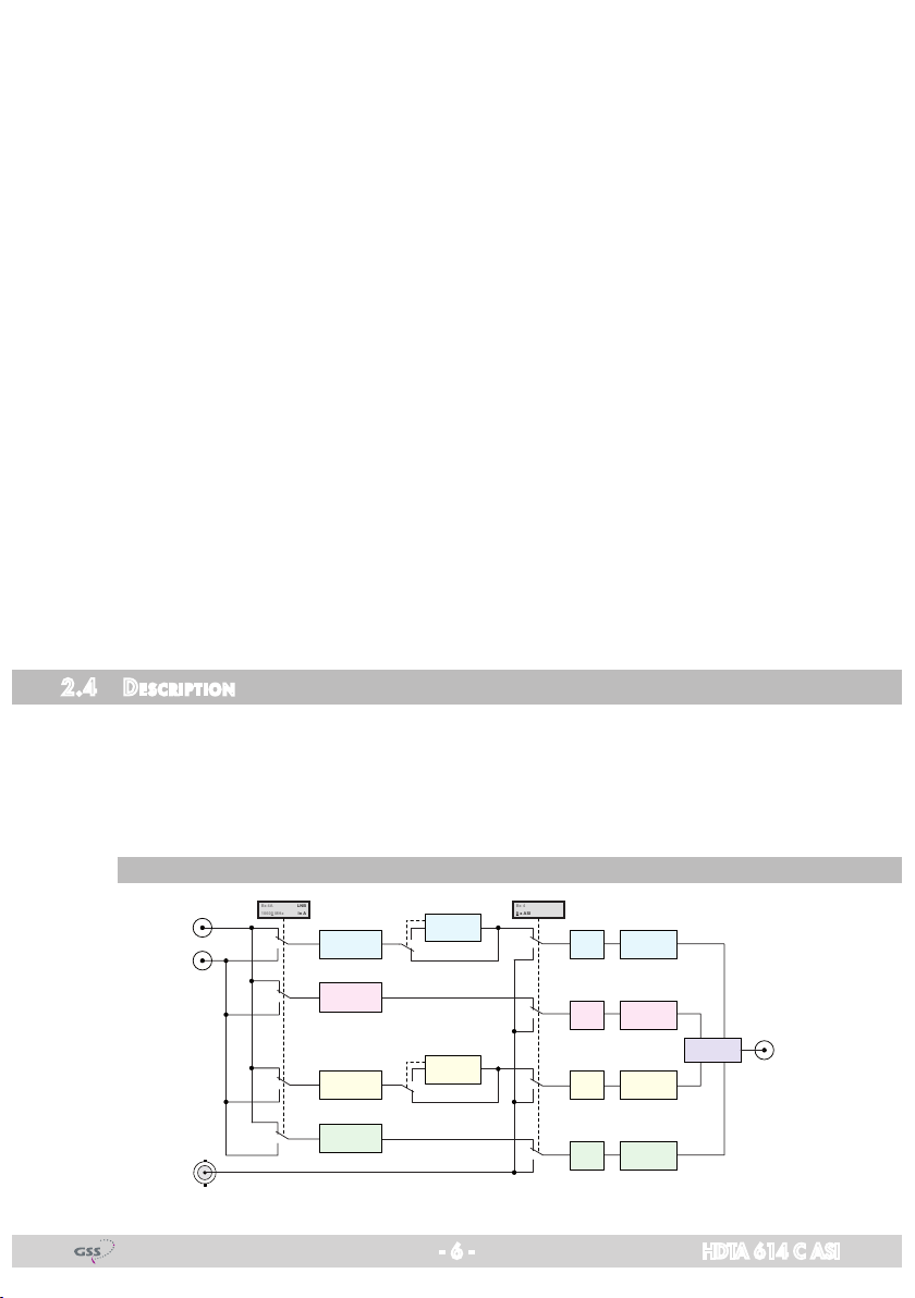
2.4 des CriPtion
The quad transmodulator cassette converts stations modulated according to
DVB-S /
for feeding into a cable network.
DVB-S2
standard (also 16/2 APSK) into four QAM modulated signals
The
cassette
has two digital SAT IF inputs, an
ASI input and one RF output.
bloCk d i agram
ASI
SAT IN "A"
SAT IN "B"
ASI IN
Tuner "A"
Tuner "B"
Tuner "C"
Tuner "D"
CA-Modul
CA module
CA-Modul
CA module
- 6 - HDTA 614 C ASI
OFF
Modulator
TPS
"A"
Modulator
TPS
"B"
TPS
TPS
Modulator
"C"
Modulator
"D"
Combiner
RF OUT
general
The cassette is equipped with four channel strips ("A" … "D"). The channel
strips consist of the digital tuners, the digital signal preparation units and the
output converters.
For channel strips A/B resp. C/D adjacent channel setting is fixed.
The channel strips are indicated in the head-end station display with "Bx …A"
… "Bx …D". Using adequate CA modules scrambled channels can be descrambled via tuner "A" and "C".
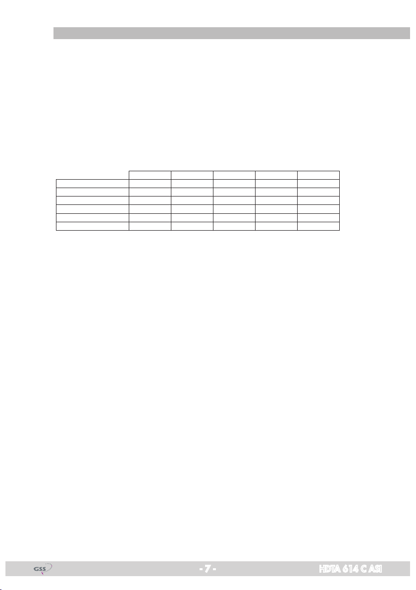
As signal source of the channel strips, tuners or the ASI input can be selected
according to the table below:
0xASI OFF Tuner A Tuner B Tuner C Tuner D 2
1xASI D Tuner A Tuner B Tuner C ASI 2
2xASI B/D Tuner A ASI Tuner C ASI 2
2xASI C/D Tuner A Tuner B ASI ASI 1
3xASI B/C/D Tuner A ASI ASI ASI 1
4xASI A/B/C/D ASI ASI ASI ASI 0
The control of the cassette takes place via the control unit of the head-end station.
Line A Line B Line C Line D CA
Four LEDs provide an indication of the SAT IF input signal quality based on
their colour and indicate if the respective channel strip is switched on (LED illuminates) or off. If there is an overflow of the output data rate, the corresponding LED blinks red/green.
The integrated TPS module (Transport Stream Processing) processes the data
of the transport streams.
Channel as well as frequency setting is possible for modulators "A" and "C".
The modulators "B" and "D" work at a spacing of + 8 MHz to modulators"A"
and "C". Herein only frequency setting (frequency spacing of channel strips
"A <–> B" and "C <–> D") is possible to reduce the bandwidth at signals of
low data rates.
The QAM modulated RF output signals are sent through the RF output of the
cassette to the output collector. The common output level of the channel strips
can be set at the output collector.
When the head-end station is switched on, the two-line LC display shows the
software version of the control unit. To operate this cassette the software version of the control unit must be "V 44" or higher. You can find the current operating software for the control unit and the cassette, the software "BE-Flash"
and the current assembly instructions on the website "www.gss.de/en".
The cassette is (with exception of STC 332) intended for use in the
STANDARD LINE
- 7 - HDTA 614 C ASI
head-end stations.

2.5 soft ware q u ery
Control unit
If necessary, you can activate the indication of the software version of the
control unit manually:
• Press any two keys on the control unit of the head-end station simultaneously
until the display goes dark and the software version, e.g. "V 44" appears.
Cassette
The software version of the cassette is shown in the display after activating the
cassette (see page 19).
2.6 how the tPs mod ule wo r ks
After decoding signals, the demodulated data streams and the data stream fed
via the ASI socket can be accessed via the integrated TPS module. These data
streams, also called transport streams, contain several stations in all their components (video, audio, data and service information), which can be changed
using the TPS module.
stati on filter
Individual stations can be deleted. This reduces the data rate and, conse-
quently, the output symbol rate.
Changi ng the trans Port s t ream a nd orgnet-id
The transport stream ID can be changed. If the stations of a transponder are
split into the transport streams of different channel strips, a new identification
must be allocated to the "new" transport streams to realise the channel search
of the settop boxes connected without mistakes.
If the ORGNET-ID is changed a new NIT must be generated.
Changi ng the nit
The transport stream contains data in the form of tables which the receiv-
ers evaluate and require for convenient use. The TPS module can adjust the
"Network Information Table" (NIT) to accommodate the new station data. The
"NIT" contains data which is required by the set-top boxes connected to the
cable network for the automatic search feature.
- 8 - HDTA 614 C ASI

2.7 exP la nat i o n of t h e term "sym bol r ate"
Modulation schemes such as QPSK and QAM transmit multiple bits simultane-
ously. These are referred to as symbols. In addition to the user data flow which
transmits video and audio information, error correction bits are transferred.
The FEC number states the ratio of user bits to the complete transmitted bits.
The output symbol rate is calculated as follows:
256-QAM: SR (A) = FEC x 1/4 x SR (E)
128-QAM: SR (A) = FEC x 2/7 x SR (E)
64-QAM: SR (A) = FEC x 1/3 x SR (E)
32-QAM: SR (A) = FEC x 2/5 x SR (E)
16-QAM: SR (A) = FEC x 1/2 x SR (E)
4-QAM: SR (A) = FEC x 1/1 x SR (E)
Example:
Output symbol rate SR (A) 64-QAM,
Input symbol rate SR (E) = 27,500
FEC= 3/4,
kSymb/s
SR (A)
= 3/4 x 1/3 x 27,500
kSymb/s
=
6,875 kSymb/s
—> If no "FEC" is stated in the station lists, it can be assumed to be "FEC
= 3/4".
tr an sPonder w ith a very low s ymbol rat e (sCPC stat i o n)
The extremely low data rate means that the output symbol rate is very low. If
there are reception problems with different digital receivers, set output symbol
rate to a higher value.
defined s ymbo l rat es
Some cable operators specify a fixed symbol rate (e.g. 6,900 kSymb/s).
- 9 - HDTA 614 C ASI
3 as s e m b l y
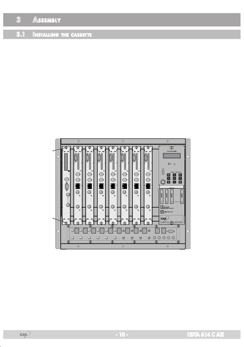
3.1 installi ng the C assette
– Ensure the head-end station is mounted so it will not be able to vibrate.
Avoid, for example, mounting the head-end station onto a lift shaft or any
other wall or floor construction that vibrates in a similar way.
– Before installing or changing a cassette unplug the power cable from the
mains power socket.
• Remove the fastening screws 1 of an unoccupied slot from the bracket of
the head-end station.
• Insert the cassette in this slot and push it into the housing.
• Align the cassette and apply slight pressure to connect it to the connections
of the board and the RF bus bar.
• Fasten the cassette with the screws 1.
1
1
- 10 - HDTA 614 C ASI
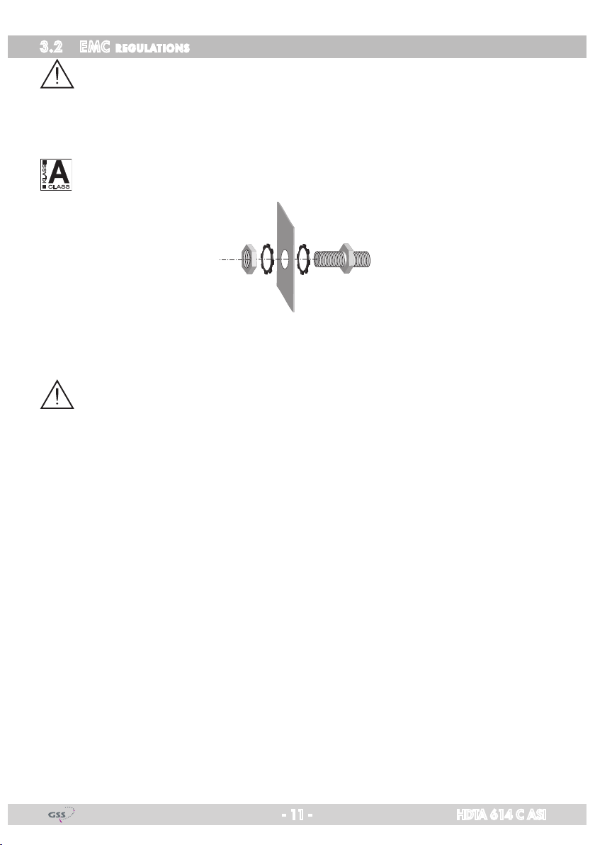
3.2 emC regulations
To comply with the current EMC regulations, it is necessary to connect the lines
leading in and out of the head-end station using cable terminals.
When mounting the cassette in a head-end station which is installed in a 19"
cabinet, make sure the connections leading in and out for the 19" cabinet are
made using cable terminals.
The attenuation of shielding of the connection lines for ASI and antenna must
KLASSE
CLASS
meet the requirements for "Class A".
• Insert the required number of cable terminals in the openings provided in
the head-end station or in the 19" cabinet.
Tighten the nuts on the cable terminals until the teeth on the lock washer have
penetrated the exterior coating and a good connection is made between the housing and cable terminals.
- 11 - HDTA 614 C ASI
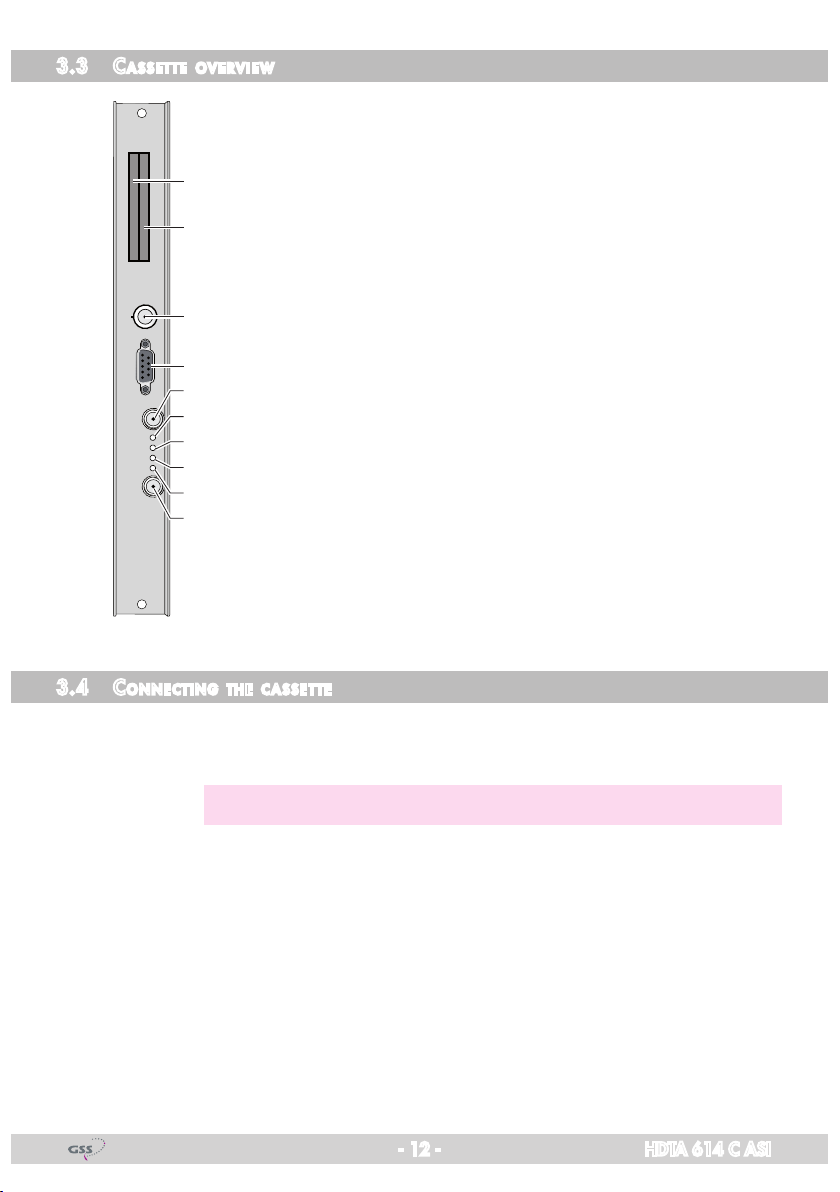
3.3 Cas sette overv iew
1 Slot for CA module of "tuner A"
2 Slot for CA module of "tuner C"
3 ASI input
1
4 D-SUB socket "RS 232"
5 SAT input "A"
2
6 Status LED of channel strip "A"
7 Status LED of channel strip "B"
3
8 Status LED of channel strip "C"
9 Status LED of channel strip "D"
0
4
5
SAT input "B"
6
7
3.4 Con neCting the C a ssette
The operating software of the cassette can be updated via the
8
9
9-pin D-SUB socket "RS 232" using a PC or notebook and the
0
software "BE-Flash". You can find the current operating software
on the website
"www.gss.de/en".
•
• If required connect the ASI input 3 to the ASI output of a corresponding
•
- 12 - HDTA 614 C ASI
Connect "
of the SAT IF input distributors.
signal source.
Connect the head-end station to the mains power supply.
SAT input A
—> Avoid wide differences in level at the inputs!
" 5 and "
SAT input B
" 0 to the respective outputs
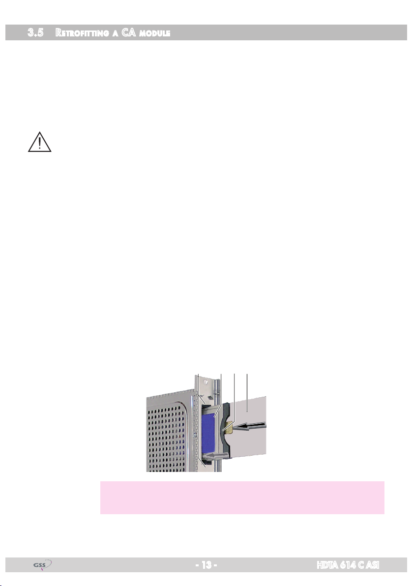
3.5 retr o fitting a Ca module
The cassette is equipped with two common interfaces. This allows you to con-
nect two CA modules for various scrambling systems and service providers.
Scrambled channels can only be descrambled with a CA module suitable for
the scrambling system and the corresponding smart card. The smart card contains all the information for authorisation, descrambling and subscription.
Caution
– Check with the distributor or manufacturer of the CA modules to be used
to ensure that they are suitable for descrambling several channels.
– The hardware and software of this cassette have been thoroughly prepared
and tested.
– Any changes made by programme provider to the structures in the pro-
gramme data might impair or even prevent this function.
– When working with the CA modules, please read the corresponding oper-
ating manuals from the respective providers.
• Insert the smart cards into the CA modules so that the chip 3 on the smart
card 1 faces the thicker side (top) of the CA module 2.
• Insert the CA modules into the slots 4 with the top sides of the CA modules
in left direction.
• Push the CA modules without canting into the guide rails of the CA slots 4
and contact them to the common interfaces.
34 12
—> If the QAM module is inserted in the head-end station, the left com-
mon interface is assigned to tuner A, the right one to tuner C.
- 13 - HDTA 614 C ASI
 Loading...