

Page 1

Grundig SAT SystEms
Assembly Instructions
A
CLASS
KLASSE
Head-End Digital Modulator HDTV
HDTV 610 CI TPS
A
KLASSE
CLASS
GSS
Grundig SAT Systems GmbH
Beuthener Straße 43
English
Assembly Instructions
D-90471 Nuremberg
Phone: +49 (0) 911 / 703 8877
Fax: +49 (0) 911 / 703 9210
E-mail: info@gss.tv
Internet: http://www.gss.tv
Page 2

- 2 -
Contents
1 Safety regulations .....................................................................................................4
2 General information .................................................................................................4
2.1 Packing contents ..........................................................................................4
2.2 Meaning of the symbols used ........................................................................5
2.3 Technical data .............................................................................................5
2.4 Description .................................................................................................6
2.5 Software query ............................................................................................7
2.6 How the TPS module works ...........................................................................7
2.7 Explanation of the term “symbol rate” ............................................................8
2.8 Bandwidth-efficient assignment of cable channels with low bandwidths ..............9
3 Assembly ...............................................................................................................10
3.1 Installing the cassette ..................................................................................10
3.2 EMC regulations ........................................................................................10
3.3 Connecting the cassette ..............................................................................11
3.4 Retrofitting a CA module ............................................................................12
4 The control panel at a glance ..................................................................................13
4.1 Menu items ...............................................................................................13
4.2 Control panel ............................................................................................13
5 Programming .........................................................................................................14
5.1 Preparation ...............................................................................................14
5.2
Notes on level setting .................................................................................14
5.3 Programming procedure .............................................................................15
5.3.1 Channel strips “A” without CA module and “B” ..................................15
5.3.2 Channel strip “A” with CA module ....................................................17
5.4 Programming the cassette ..........................................................................18
Selecting the cassette .................................................................................18
Selecting the channel strip ..........................................................................19
Selecting channel / frequency setting ...........................................................19
Setting the output channel ...........................................................................20
Setting the output frequency ........................................................................21
Switching the modulator off or on ................................................................21
Adjusting the output levels of the channel strips .............................................21
Setting the LNB oscillator frequency .............................................................22
Setting the input symbol rate .......................................................................23
Setting the DVB mode ................................................................................23
Setting the input frequency ..........................................................................24
Testing the signal to noise ratio ....................................................................24
Setting the station filter ...............................................................................26
Setting the QAM modulation ......................................................................28
Inverting the user signal ..............................................................................29
Setting stuffing ...........................................................................................29
Setting a substitute signal in the case of an incorrect input signal ....................30
Network Information Table (NIT) ..................................................................31
Saving settings ..........................................................................................32
- 2 -
Page 3

- 3 -
5.4.1 Operation with a CA module ............................................................32
Setting the operating voltage for the CA module .................................32
Setting the PID monitoring ................................................................33
Configuring the CA module ..............................................................34
Setting the station filter .....................................................................35
6 Channel and frequency tables .................................................................................37
- 3 -
Page 4

- 4 -
1 Safety regulations
Caution
• Assembly, installation and servicing should be carried out by authorised
electricians.
• Switch off the operating voltage of the system before beginning with assembly
or service work or pull out the mains plug.
• Do not perform installation and service work during thunderstorms.
• Install the system so it will not be able to vibrate…
- in a dust-free, dry environment
-
in such a manner that it is protected from moisture, fumes, splashing water and
dampness
- somewhere protected from direct sunlight
- not within the immediate vicinity of heat sources
- in an ambient temperature of -20 °C to +50 °C.
• Ensure that the head-end station is adequately ventilated.
Do not cover the ventilation slots.
• Beware of short circuits
• No liability is accepted for any damage caused by faulty connections or inappropriate handling.
• Observe the relevant standards, regulations and guidelines on the installation and
operation of antenna systems.
• Earth the
and VDE 0855 (earthed, equipotential bonding rail).
• For further information please read the assembly instructions for the head-
end station used.
SAT receiver in accordance with DIN EN 50083-1 / EN 60728-11
Take action to prevent static discharge when working on the device.
2 General information
2.1 Packing contents
1 cassette HDTV 610 CI TPS
2 HF cables
1 CD (assembly instructions)
1 Brief assembly instructions
- 4 -
Page 5

2.2 Meaning of the symbols used
Important note
—> General note
• Performing works
2.3 Technical data
The devices meet the following EU directives:
2006/95/EC, 2004/108/EC
The product fulfils the guidelines and standards for CE labelling.
HF input
Frequency range: 925 … 2150 MHz
Level range: 60 dBµV … 80 dBµV
DVB-S modes: DVB-S 1/2 , 2/3 , 3/4 , 5/6 , 7/8
DVB-S2 modes: QPSK 1/2 , 3/5 , 2/3 , 3/4 , 4/5 , 5/6 , 8/9 , 9/
8PSK
3
/5 , 2/3 , 3/4 , 5/6 , 8/9 , 9/
Symbol rate DVB-S: QPSK: 2 … 45 MSymb/s
Symbol rate DVB-S2: QPSK: 10 … 30 MSymb/s
8PSK: 10 … 31 MSymb/s
10
10
HF output
Channels: S21 … C69
Frequency range: 42.0 MHz … 860.0 MHz
Output level: typ. 97 dBµV
Output impedance: 75 Ω
Connections
SAT inputs: 2 F sockets
HF output: 1 IEC socket
Connection strip (10-pin): for supply voltages and control circuits
RS 232 socket: serial interface for software update
Conditional access: several channels can be decoded.
- 5 -- 5 -
Page 6

- 6 -
2.4 Description
The twin transmodulator cassette is a QPSK-converter, which converts all stations modulated according to DVB-S /
ed cable signals.
The
cassette
has two digital SAT IF inputs and an HF output. It
DVB-S2
standard into two QAM-modulat-
is equipped with two channel strips (“A” and “B”). The channel strips consist of
the digital tuners, the digital signal preparation units and the output converter.
The channel strips are indicated in the head-end station display with “Bx …A”
and “Bx …B”. Using an adequate CA module encoded channels can be decoded via channel strip “A”. The control of the cassette takes place via the control
unit of the head-end sta
tion.
Two LEDs indicate if the respective channel strip is switched on (LED illuminates)
or off, and also provide an indication of the signal quality based on their
colour. Additionally the quality of the data stream received is displayed
(“CN…”).
The integrated TPS module (Transport Stream Processing) processes the data
from the demodulated transport streams. This enables service information (NIT –
Network Information Table) to be changed, data rates to be increased (stuffing)
and for individual stations to be deleted from the transport stream (thus optimising bandwidth for the other stations being transmitted).
The HF output signals are sent through the HF output of the
cassette
to the output
collector. The common output level of the channel strips can be set at the output
collector.
When the head-end station is switched on, the two-line LC display shows the
software version of the control unit.
To operate this cassette the software version of the control unit must be “V 37”
or higher. You can find the current operating software for the control unit and
the cassette, the software “BE-Flash”
and the current assembly instructions
website “www.gss.tv”.
The
cassette is
designed for use in the following head-end stations:
– STC 1200
– STC 316
– STR 19-8
on the
- 6 -
Page 7

- 7 -
2.5 Software query
Control unit
If necessary, you can activate the indication of the software version of the control unit manually:
• Press any two keys on the control unit of the head-end station simultaneously
until the display goes dark and
the software version, e.g. “
V 37
” appears.
2.6 How the TPS module works
After decoding QPSK- or 8PSK-modulated signals, the demodulated data stream
can be accessed via the integrated TPS module. This data stream, also called
transport stream, contains several stations in all their components (video, audio,
data and service information), which can be changed using the TPS module.
The individual functions
Station filter
Individual stations can be deleted. This reduces the data rate and, consequently,
the output symbol rate required.
Stuffing
The transport stream is padded using what is known as zero data. This ensures
a steady and constant output symbol rate.
Changing the NIT
The transport stream contains data in the form of tables which the receivers
evaluate and require for convenient use. The TPS module can adjust the “Network Information Table” (NIT) to accommodate the new station data. The “NIT”
contains data which is required by the set-top box for the automatic search
feature.
- 7 -
Page 8

- 8 -
2.7 Explanation of the term “symbol rate”
Modulation schemes such as QPSK and QAM transmit multiple bits simultaneously. These are referred to as symbols. In addition to the user data flow which
transmits video and audio information, error correction bits are transferred. The
FEC number states the ratio of user bits to the complete transmitted bits. The
output symbol rate is calculated as follows:
1
256-QAM: SR (A) = FEC x
/4 x SR (E)
128-QAM: SR (A) = FEC x 2/7 x SR (E)
64-QAM: SR (A) = FEC x 1/3 x SR (E)
32-QAM: SR (A) = FEC x 2/5 x SR (E)
16-QAM: SR (A) = FEC x 1/2 x SR (E)
4-QAM: SR (A) = FEC x 1/1 x SR (E)
Example:
Output symbol rate 64-QAM,
Input symbol rate SR (E) = 27,500
SR (A)
= 3/4 x 1/3 x 27,500
SR (A)
=
6,875 kSymb/s
FEC= 3/4,
kSymb/s
kSymb/s
Note:
If no “FEC” is stated in the station lists, it can be assumed to be
“FEC = 3/4”.
Reception from a transponder with a very low symbol rate
(SCPC station)
The extremely low data rate means that the output symbol rate is very low. If
there are reception problems with different digital receivers, set output symbol
rate to a higher value.
Defined symbol rates
Some cable operators specify a fixed symbol rate (e.g. 6,900 kSymb/s).
- 8 -
Page 9
- 9 -
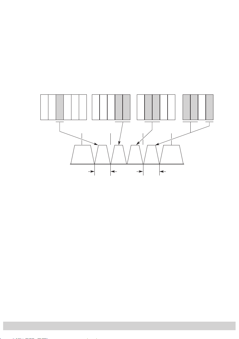
2.8 Bandwidth-efficient assignment of cable channels with low bandwidths
(SelecPlex®)
Channels with low bandwidths are the result of filtering out stations which are
not required. These “narrow” channels can then be arranged in one channel to
save space. To do this, activate the “Setting the output frequency” menu (assignment outside the official channel raster).
—> The required bandwidth (in kHz) is roughly equal to the symbol rate
(kSymb/s) plus 20% in MHz.
Astra 19,2° East Eutelsat 7° EastTürksat 42° EastEutelsat 13° East
TV 5
RTM 1
ESC 1
RAI UNO
DW TV
RTP
SISAL TV
TV Bulgaria
Mediolanum
Nile TV
Nile News
Super Sport
Viva
Gala
Fantasy
Cine 5
TVP 1
TVP 2
S21 S22 S23 S24
TV Polonia
TVP 3
ESC 1
3 MHz
64 QAM
2.5 Ms/s
Nile TV
Nile News
Viva
Gala
TVP 1
TVP 2
TVP 3
4 MHz
64 QAM
3.3 Ms/s
- 9 -
Page 10
- 10 -
3 Assembly
A
CLASS
KLASSE
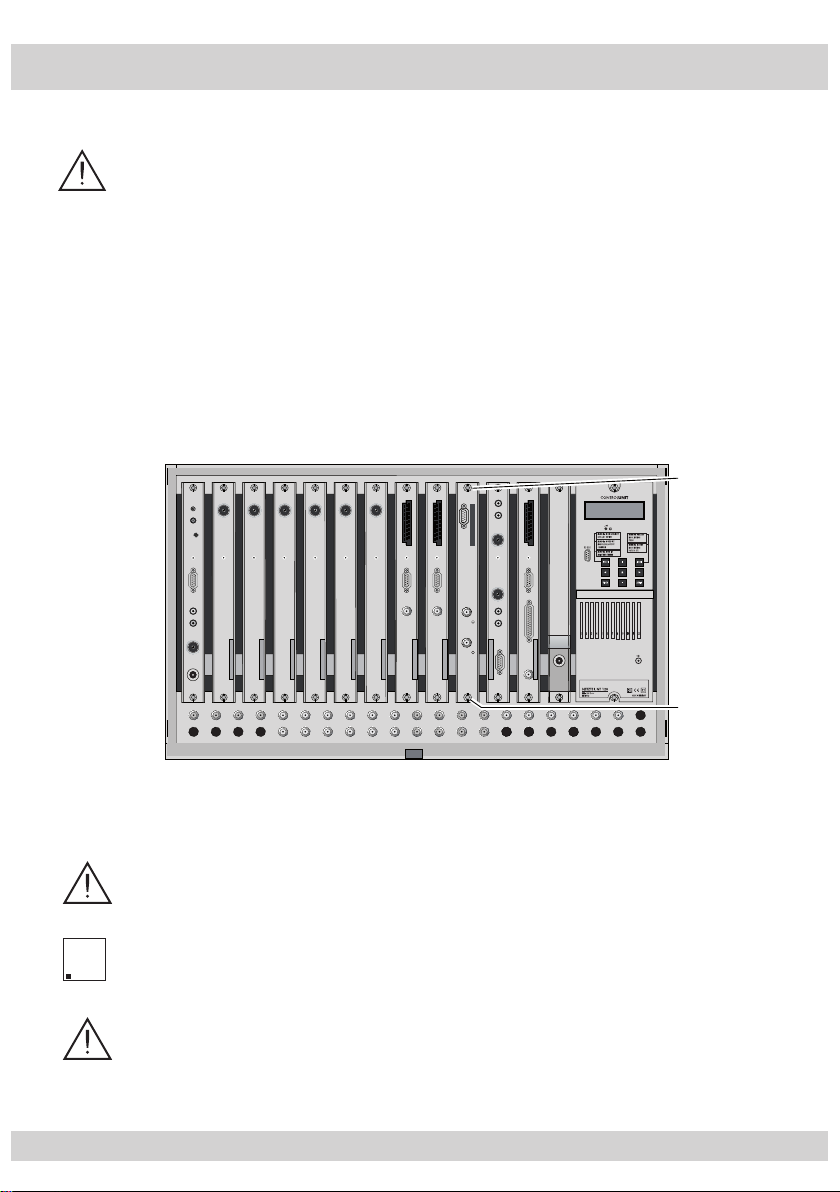
3.1 Installing the cassette
– Ensure the head-end station is mounted so it will not be able to vibrate.
Avoid, for example, mounting the head-end station onto a lift shaft or any
other wall or floor construction that vibrates in a similar way.
– Before installing or changing a cassette unplug the power cable from the
mains power socket.
• Remove the fastening screws
1 of an unoccupied slot from the bracket of the
head-end station.
• Insert the cassette in this slot and push it into the housing.
• Align the cassette and apply slight pressure to connect it to the connections of
the board and the HF bus bar.
• Fasten the cassette with the screws 1.
0°
CASSETTE
CASSETTE
CASSETTE
CASSETTE
CASSETTE
CASSETTE
CASSETTE
CASSETTE
CASSETTE
CASSETTE
CASSETTE
CASSETTE
MESSAUSGANG
ACHTUNG!
Vor dem Cassettenwechsel
unbedingt Netzstecker ziehen!
CAUTION!
Before changing cassettes remove
mains plug!
A
3.2 EMC regulations
To comply with the current EMC regulations, it is necessary to connect the
lines leading in and out of the head-end station using F terminals.
The attenuation of shielding of the connection lines must meet the require-
A
KLASSE
CLASS
ments for “Class A”.
When mounting the cassette in a STR 19-8 head-end station which is in-
stalled in a 19” cabinet, make sure the connections leading in and out for
the 19” cabinet are made using F terminals.
- 10 -
Page 11
- 11 -
• Insert the required number of F terminals in the openings provided in the
head-end station or in the 19" cabinet.
—> F terminals are not included in the scope of delivery.
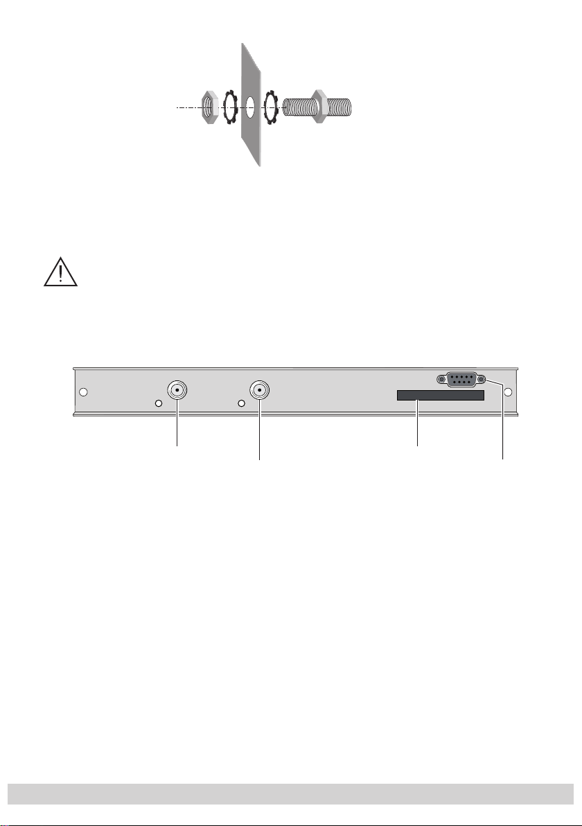
3.3 Connecting the cassette
Tighten the nut on the F terminal until the teeth on the lock washer have penetrated the exterior coating and a good connection is made between the
housing and F terminal.
SAT input "B"
SAT input "A"
•
Plug the SAT input cables into the SAT input sockets “
strip “A”) and “
•
Connect the head-end station to the mains power supply.
SAT input B
” 1 (channel strip “B”).
Slot for
CA module
SAT input A
” 2 (channel
3 Slot for a CA module
4 “RS 232 socket”
The operating software of the
socket “RS 232” using a PC or notebook and the software “BE-Flash”.
You can find the current operating software on the website “www.gss.tv”.
cassette
can be updated via the 9-Pin D-SUB
RS 232
- 11 -
Page 12

- 12 -
3.4 Retrofitting a CA module
The cassette is equipped with a common interface. It allows you to connect
a CA module for various encryption systems and service providers. Encoded
channels can only be decoded with a CA module suitable for the encoding
system and the corresponding smart card. The smart card contains all the information for authorisation, decoding and subscription.
Caution
– Check with the distributor or manufacturer of the CA module to be
used to ensure that it is suitable for decoding several channels.
– The hardware and software of this cassette have been thoroughly pre-
pared and tested.
– Any changes made by program vendors to the structures in the program
data might impair or even prevent this function.
– When working with the CA module, please read the corresponding op-
erating manual from the respective provider.
• Insert the smart card into the CA module so that the chip on the smart card
faces the thicker side (top) of the CA module.
• Insert the CA module into the slot
module facing the top side of the cassette.
• Push the CA module without canting into the guide rails of the common interface slot and contact it to the common interface.
3 (s. chap. 3.3) with the top side of the CA
- 12 -
Page 13

- 13 -
4 The control panel at a glance
4.1 Menu items
Program the
cassette
using the buttons on the control unit of the head-end station.
The two-line display of the control unit then shows the menus.
The parameters and functions to be set are underlined.
Use the key to select the following main menu items:
– Channel strip
– Selecting channel / frequency setting
– Output channel / output frequency
BE–Remote V 37
please wait . . .
– Output level
– LNB oscillator frequency
– Input symbol rate
– Input frequency
– Station filter
– QAM modulation
– Stuffing
– Substitute signal
– Network Information Table (NIT)
4.2 Control panel
The key pad on the head-end station is used to scroll through the menus and
menu items one at a time:
scrolls forward through the menus.
◀
▶
/
select parameters in the menus.
set values, initiate actions.
selects sub-menus.
AUDIO
M
scrolls backward through the menus.
saves all entries.
- 13 -
Page 14

- 14 -
5 Programming
5.1 Preparation
• Connect the test receiver to the HF output or the test output of the head-end
station.
• Set the output channel / output frequency of the
cassette
and adjust the TV test receiver to this channel.
•
Switch on the channel strip (modulator) if necessary (s. page 21). For each
channel strip, there is a status LED which indicates if the channel strip is
switched on.
(s. page 20 / 21)
Status LED
Channel strip
"B"
Status LED
Channel strip
"A"
• Balance the output levels of the channel strips “A” and “B” if the difference in
level is ≥ 1 dB (page 21).
5.2
Notes on level setting
In order to prevent interference within the head-end station and the cable system, the output level of the cassette must be lowered by 10 dB compared to
analogue cassettes at 64 QAM, and by 4 dB compared to analogue cassettes
at 256 QAM.
• Measure the output levels of the other
cassettes
and tune them to a uniform
output level using the appropriate level controls or software dependent on the
head-end station used.
Please regard the assembly instructions of the respec-
tive head-end station.
- 14 -
Page 15

- 15 -
5.3 Programming procedure
5.3.1 Channel strips “A” without CA module and “B”
Ein / On
BE–Remote
please wait …
t > 10 s
Bx 1A
C5-12,S3-24
+
Box 4
V 1
Bx 4A
V 1
Bx 4A
Channel
Bx 4A
S21
DVBS2-TPS
DVBS2-TPS
V 37
TWIN-SAT
C07
– – –
S21
OUTPUT
OUTPUT
on
A / B
◀
▶
/
Bx 1A
Böx 4
Bx 5A
C5-12,S3-24
C5-12,S3-24
BD3
Channel / Freq.
on / off
TWIN-SAT
TWIN-SAT
DVBT-DVBT
C09
C07
C07
Bx 4A
0 dB
Bx 4A
10600 MHz
Bx 4A
◀
▶
/
27500
DVB-S
LEVEL
LNB
SYMBOL
◀
/
◀
/
0 … -10 dB
▶
▶
DVB-S / DVB-S 2
- 15 -
Page 16

- 16 -
◀
▶
/
Bx 4A
11836 -1.8
FREQ
CN 12
Bx 4A
12.0 dB
C/N
(+ 9.6) OK
Anzeige: Signalqualität
Display: Signal quality
Bx 4A
Filter
ohne CA-Modul
without CA module
Kanalzug “B”
Channel strip “B“
Bx 4A
4 … 256
64-QAM
Bx 4A
SR=6900 (6325)
Bx 4A
Null Packets
PROGRAM
off
QAM
normal
STUFFING
FAILURE
Das Erste
▶
Bx 4A
Filter
Kanalzug “A” mit CA-Modul
Channel strip “A“ with CA module
◀
▶
/
normal / inverse
◀
▶
/
Null Packets … Single Carrier
PROGRAM
01/10Bx 4A TV +
on
Programme entfernen / hinzufügen
Removing / activating stations
nächster Service (Programm)
◀
▶
/
next service (station)
on / off
!
Bx 4A
on / off Make
off
=> Make
M
NIT
▶
- 16 -
Page 17

- 17 -
5.3.2 Channel strip “A” with CA module
M
Bx 4A 01/03
Information *)
*) Die angezeigte Information ist
abhängig vom verwendeten
CA-Modul.
The information displayed is
dependent on the CA module
used.
MENU
Bx 4A
Supply
Bx 4A
PID Check
Bx 4A
Menu <=
◀
CA
5.0 V
CA
on
CA
=> Edit
▶
3.3 V / 5.0 V
on / off
Bx 4A TV X
. . . .
S
Bx 4A
Menu <=
04/09
CA
=> Edit
X / 0
X – entschlüsselt
decrypted
0 – verschlüsselt
encrypted
◀
▶
/
nächster Service
next service
- 17 -
Page 18

- 18 -
5.4 Programming the cassette
Ein / On
BE–Remote
please wait …
V 37
t > 10 s
Box 4
V 1
DVBS2-TPS
– – –
Bx 1A
C5-12,S3-24
TWIN-SAT
C07
Bx 1A
C5-12,S3-24
TWIN-SAT
C07
Böx 4
C5-12,S3-24
TWIN-SAT
C07
Bx 5A
BD3
DVBT-DVBT
C09
+
5
A
3
—> Pressing the
button for longer than 2 seconds cancels the programming procedure. This takes you back to the program item “Selecting
the cassette” from any menu. Any entries that have not been saved are
reset to the previous settings.
M
—> Entries in the menus can be saved by pressing the
key. You are taken
back to the “Selecting the cassette” menu item.
• Switch on the head-end station
—> The display shows the software version (e.g. V 37)
—> The processor reads the
cassettes
‘ data
(approx. 10 seconds).
_
Selecting the cassette
• Select the
cassette
x
D
you want to program (e.g. Box 4) by
-
09
repeatedly pressing the button if necessary.
• By pressing the button, activate channel strip “A”.
- 18 -
Page 19

- 19 -
Selecting the channel strip
Bx 4A
V 1
DVBS2-TPS
S21
A / B
Selecting channel / frequency setting
• By pressing
—> The display shows e.g. the menu “
“Bx” stands for
“4” for
, select channel strip “A” or “B”
Bx 4A DVBS2-TPS
slot
cassette
4
(box),
”:
“A” for channel strip “A”
”DVBS2-TPS” Type of cassette
”S21” Channel set
• Press the button.
—> The “Selecting channel / frequency setting” –
“OUTPUT” menu is activated.
In this menu, you can choose the channel or frequen cy setting
for the adjustment of the HF output. The channel setting covers the range of channels S21 … C69, the frequency setting
covers the range from 42.0 MHz to 860.0 MHz.
The QAM signal is normally transmitted with a bandwidth of
8 MHz. This means that you can only use the channel centre
frequency of the existing channel raster in the range of channels S21 … C69 (frequency raster 8 MHz). The CCIR channel raster is 7 MHz in the range of the lower frequency bands
(channels C2 … S20). Therefore the frequency setting is used
here. If one uses the existing channel raster of 7 MHz in these
channel ranges, this will result in interference (overlapping)
with the 8 MHz QAM signal packages, thus causing transmission problems.
For programming in these channel ranges and in the frequency ranges below them, we recommend starting with channel
S21 / 306 MHz going back in steps of 8 MHz, or reducing
- 19 -
Page 20

- 20 -
the bandwidth of the QAM output signal by removing sta-
Bx 4A
Channel
OUTPUT
Channel / Freq.
Bx 4A
S21
OUTPUT
on
on / off
▶
◀
/
tions.
Using “SelecPlex®“ only the frequency setting can be used.
• Use
to select channel setting “Channel” or frequen-
cy setting “Freq.”.
• Press the button.
—> The “Setting the output channel” or “Setting the out-
put frequency” – “OUTPUT” menu is activated.
—>
If frequency setting is selected continue on page 21 with
“Setting the output frequency”.
Setting the output channel
In this menu you set the output channel of the channel strip.
Additionally the modulator of the channel strip can be
switched off or on (page 21).
•
Use the buttons to set the output channel.
- 20 -
Page 21

- 21 -
Setting the output frequency
Bx 4A
466.00
OUTPUT
on
▶
◀
/
▶
◀
/
on / off
Bx 4A
0 dB
LEVEL
0 … -10 dB
In this menu you set the output frequency of the channel strip
(42.0 … 860.0 MHz)
nel strip
• Use the
can be switched off or on.
◀
/
. Additionally the modulator
▶
buttons to position the cursor under the digit
of the chan-
to be set for the frequency display then use to set
the output frequency wished.
Switching the modulator off or on
• To switch off the modulator place the cursor under “on”
using the
▶
button and switch “off” the modulator of the
channel strip using the buttons.
—>
The switched off modulator is indicated by “ - - - “ in
the display.
• If the modulator is switched “off” use the to switch
it “on”.
• Press the button.
—>
The “Adjusting the output levels of the channel strips”
–
“LEVEL” menu is activated.
Adjusting the output levels of the channel strips
This menu item is used to set the output levels of the modulators of the channel strips “A” and “B” to the same value.
- 21 -
Page 22

- 22 -
• Measure and note down the output level of the channel
▶
◀
/
Bx 4A
10600 MHz
LNB
strip.
• Save the settings by pressing the M button.
• Select the other channel strip
(page 19),
measure and note
down its output level.
• Activate the
“LEVEL” menu of the channel strip with the
higher output level.
• By pressi
ng adjust the higher output level of one
channel strip to the lower output level of the other channel
strip incrementally from “0
” to “
–10 dB”.
• Press the button.
—> The “Setting the LNB oscillator frequency” – “
menu is activated.
Setting the LNB oscillator frequency
Set the oscillator frequency of the LNB used in this menu.
LNB
”
◀
• Use
▶
to place the cursor under the digit to be set for
/
the frequency display.
• Press to enter the oscillator frequency of the LNB
used.
• Press the button.
—> The “Setting the input symbol rate” – “SYMBOL” menu
is activated.
- 22 -
Page 23

- 23 -
Setting the input symbol rate
Bx 4A
27500
SYMBOL
DVB-S
▶
◀
/
▶
◀
/
DVB-S / DVB-S 2
The symbol rates of the satellite transponders can be found in
the current channel table of the satellite operator, in various
satellite magazines and in the Internet.
◀
• Use
▶
to position the cursor under the digit to be set
/
for the symbol rate displayed.
• Press
to enter the values of the symbol rate.
Setting the DVB mode
The cassette recognizes the transmitted DVB mode and
switches over between the normal QPSK mode (DVB-S) and
the DVB-S2 mode. Receiving stations with DVB-S2 mode,
we suggest to preset the DVB mode to shorten the time for
searching stations.
• Use the
set the required DVB-S2-mode with the buttons
▶
button to place the cursor under “DVB-S” and
.
• Press the button.
—> The “Setting the input frequency” – “FREQ” menu is
activated.
- 23 -
Page 24

- 24 -
Setting the input frequency
Bx 4A
11836 -1.8
FREQ
CN 12
▶
◀
/
Bx 4A
12.0 dB
C/N
(+ 9.6) OK
Anzeige: Signalqualität
Display: Signal quality
Bx 4A
11836 -1.8
FREQ
CN 12
▶
◀
/
Bx 4A
12.0 dB
C/N
(+ 9.6) OK
Anzeige: Signalqualität
Display: Signal quality
4A
8
Q
/
If three dots “ … “ appear in the second line of the display,
the cassette is in the “station search” mode. Please wait until
the process has finished.
Once the HF receiver has synchronised to the input signal,
any offset to the target frequency is displayed in MHz, e.g.
“– 1.8”.
If a question mark “?” appears in the second line of the display, there is no input signal present. Check the configuration
of the antenna system and head-end station as well as the
preceding settings of the cassette.
2.0 dBN+ 9.6) OK
◀
• Use
▶
to position the cursor under the digit to be set
/
of the frequency displayed.
• Press
to set the input frequency.
• Set the frequency offset shown in the display to less than
1 MHz
by varying the input frequency
using the
buttons.
• Press the button.
—> The “Testing the signal to noise ratio” – “C/N” menu
is activated.
Testing the signal to noise ratio
In this menu you can estimate the quality of the input signal.
x
1836 -1.
FRE
N 12
- 24 -
Page 25

- 25 -
Bx 4A
12.0 dB
C/N
(+ 9.6) OK
1 Current signal to noise ratio
2 This value shows the difference between the quality
of the input signal and the threshold of the tuner at
this type of modulation.
At a value lower than “5” picture dropouts can oc-
cur.
3 If “OK” is shown, the signal to noise ratio is ok.
If a value < 5 is shown under 2 the display changes
from “OK” to “??”. In this case test the input signal.
—>
In addition to the indicator in the display, there is
also a status LED which indicates the quality of the
received transport stream
Status LED
Channel strip "A"
Status LED
Channel strip "B"
LED indicator Indication
Green Signal quality is good
Yellow
Red No signal
Off
:
Signal quality is poor
The channel strip (modulator)
is switched off
• Press the button
to return to the main menu.
• Press the button.
—> The “Setting the station filter” – “PROGRAM” menu
is activated.
- 25 -
Page 26

- 26 -
Setting the station filter
Bx 4A
Filter
PROGRAM
off
01/10Bx 4A TV +
Das Erste
Bx 4A
Filter
PROGRAM
on
on / off
Programme entfern
Removing / activat
nächster Service (P
next service (statio
▶
◀
/
▶
The default setting for the station filter is “off”. In this menu
you define the stations received to be transmitted. If stations
are activated the output symbol rate increases.
If the station filter is switched off (factory default) all stations
of the transport stream passes the station filter. As soon as the
station filter is activated all stations are inactive and can be
added to the transport stream selectively.
•
Press the
button.
—> All stations from the channel strip will be read, and
then displayed with name and station type.
—> If no station is found, the following error message will
appear in the display “FILTER no Service”.
In this case, check the configuration of the antenna
system and head-end station, as well as the previously adjusted settings for the cassette.
—> The display shows e.g.:
Das Erste
Bx 4A TV + 01/10
Meaning of the indicators in the example:
“Bx 4A” – Slot 4, channel strip “A”
“TV” – TV channel type
“ + ” –
switched on.
“
01/10” – The 1st of 10 stations is being displayed.
“
Das Erste
The currently
” – Station name
- 26 -
selected
station is
Page 27

- 27 -
Further possible terms displayed:
“RA” Radio channel type
For radio stations, the back
the connected TV or test receiver is darkened.
“ – ”
* ” The star means that the TV or radio station se-
“
—> If a service number (e.g. “131”) appears instead of
• Use the
order, then use
remove them (“ – ”).
Factory default: All stations are deactivated.
•
To save changes and to activate the station filter press the
—>
The display shows “PROGRAM Filter on”.
—> If stations are activated the corresponding PIDs (au-
The currently selected station is
lected is encoded. To enable the stations, the CA
module and the appropriate smart card of the
station provider are required.
“TV” or “RA”, this indicates that an unnamed station
or an undefined data stream is being received.
◀
▶
The filter is activated.
dio, video, text) are inserted into the data stream and
the PAT and SDT tables are updated.
buttons to call up the stations in sequential
/
to activate (indicated by “ + ”) or to
button.
ground of the screen of
switched off.
Test the status of the individual stations:
If the filter is switched on, press the
you can test the settings of the station filters again or change
them if necessary.
•
In the “PROGRAM Filter on” menu the station filter can be
switched
“off” using the buttons .
- 27 -
▶
button. In this mode
Page 28

- 28 -
• Press the button.
Bx 4A
64-QAM
QAM
normal
▶
◀
/
4 … 256
normal / inverse
!
Kanalzug “A” mit CA-Modul
Channel strip “A“ with CA module
ohne CA-Modul
without CA module
Kanalzug “B”
Channel strip “B“
—
> The “Setting the QAM modulation”
– “QAM” menu is
activated when the channel strips “A” without a
module installed
and “B” are programmed.
Programming the channel strip “A” with a CA module
installed the “Setting the operating voltage for the
CA module” – “CA” menu is activated
(s. page 32).
CA
Setting the QAM modulation
In this menu, you can set the QAM modulation and invert the
user signal.
•
Use to set the QAM modulation (“4” … “256”).
—> For higher QAM modulation, the output symbol rate is
lowered. An output QAM modulation of > 64 QAM
places a large burden on the cable network. Due
to noise, delay and frequency response problems,
reception of the converted output signal can be impeded.
- 28 -
Page 29

- 29 -
Inverting the user signal
For exceptional cases and “older” digital cable receivers, the
spectral position of the user signal can be inverted.
◀
• Use
• Use
▶
to place the cursor under “normal”.
/
to set the spectral position to “inverse”.
• Press the button.
—>
The “Setting stuffing” – “STUFFING” menu is acti-
vated.
Setting stuffing
Bx 4A
SR=6900 (6325)
STUFFING
◀
▶
/
SR=6900 (= “Number 1”): Active output symbol rate
Bx 4A
SR=6900 (6325)
Number 1 Number 2
STUFFING
(6325) (= “Number 2”):
The current measured output symbol rate.
If the station filter is activated, this value is lower than
the value of the “Number 1”. The value fluctuates,
since the data rates of individual stations are dynamically modified by the broadcasters.
◀
•
Use the
▶
buttons to place the cursor under the
/
number to be changed (“Number 1”) and set the symbol
rate with the buttons .
The value set corresponds to the new output symbol rate.
- 29 -
Page 30

- 30 -
Notes:
– Increase the value of “Number 1”.
—> The “Number 1” can be increased to any value up to
7500.
– Reduce the value of “Number 1”.
With the station filter switched “on”, the “Number 1”
—>
can be decreased. To do this, observe the “Number
2” for approx. 30 seconds and note the highest value.
Add roughly 10 % to this value. Do not decrease the
“Number 1” lower than the value of “Number 2”.
Is the “Number 1” lower than “Number 2” question
marks “??” appear in the display.
Setting a substitute signal in the case of an incorrect input signal
Bx 4A
Null Packets
Bx 4A
SR=6200 (6325) ??
STUFFING
• Press the button.
—> The “Setting a substitute signal in the case of an in-
correct input signal” – “FAILURE” menu is activated.
You use this menu to set whether a QAM signal filled
with “Null Packets”, a QAM signal filled with null packets
and self-made tables
”Tables“
or a “Single Carrier” signal
should be provided as an output signal whenever an incorrect input signal occurs. Self-made tables are transmitted
furthermore.
FAILURE
Null Packets … Single Carrier
• Use the buttons to set the output signal required.
• Press the button.
—> The “Network Information Table” – “NIT” menu is ac-
tivated.
- 30 -
Page 31

Network Information Table (NIT)
Bx 4A
on / off Make
off
=> Make
M
NIT
▶
• To switch NIT on/off (“on”/” off”) press the
buttons.
• Press the ▶ button to activate NIT “Make”.
All active …-QAM cassettes must be set and ready
for reception.
—> The NIT of all …-QAM cassettes are switched on.
—> The cassette fetches all the information (output fre-
quencies, output symbol rates, etc.) it needs from all
the …-QAM cassettes in order to generate the cable
NIT. This process may take a few seconds.
Then the NIT is generated, added and sent to all
…-QAM cassettes. The other …-QAM cassettes also
add this new cable NIT. The status of all …-QAM
cassettes in the NIT menu changes to “on”.
The display shows: “read … / copy …”.
• To switch off the new NIT
The cable NITs of the other …-QAM
(”off”)
press the
button.
cassettes
stay switched on. When the cable NIT of the cassette
is
switched on again (“on”) by pressing the
button,
the previously generated NIT is added again. If you
have changed parameters in the meantime, you must
first select “
Make
” to generate a new, up-to-date
NIT.
will
- 31 -- 31 -
Page 32

- 32 -
Saving settings
• Press the
M
button.
—> Back to “Selecting the cassette” A (page 18).
—> The settings are saved.
—> If functions of the TPS module are activated, their sta-
tus is shown in the second line of the display:
“P” – The station filter is switched on
“N” – NIT activated
—> By pressing the
to the menu item “Selecting the channel strip” via B
without
—> If necessary set channel strip “B”.
5.4.1 Operation with a CA module
In order for this function of the CA module to be possible, stations capable of being decoded by the CA module you are
using and your smart card must be selected in the “Setting
the station filter” – “PROGRAM” menu (page 26).
Where both encrypted stations and unencrypted regional
broadcasters are transmitted via a single channel, short-term
picture loss may occur when switching between encrypted
and unencrypted broadcasts.
Setting the operating voltage for the CA module
In this menu the operating voltage for the CA module can
be set.
button, you will be returned
saving the programmed data
(page 19).
Bx 4A
Supply
CA
5.0 V
- 32 -
3.3 V / 5.0 V
Page 33

• Use the buttons to set the operating voltage for the
CA module.
• Press the button.
—>
The “Setting the PID monitoring” – “CA”
menu
vated.
Setting the PID monitoring
The factory default of the PID monitoring is switched on.
If particular PIDs are not decrypted the CI module is reset.
Additionally dropouts may occur if several stations are decrypted. To prevent this the PID monitoring can be switched
off.
Bx 4A
PID Check
CA
on
on / off
is acti-
• Use the
buttons to switch “off” or “on”. the PID
monitoring.
• Press the button.
—>
The “Configuring the CA module” – “CA”
vated.
- 33 -- 33 -
menu
is acti-
Page 34

- 34 -
Configuring the CA module
Bx 4A
Menu <=
CA
=> Edit
*) Die angezeigte Information ist
abhängig vom verwendeten
CA-Modul.
The information displayed is
dependent on the CA module
used.
Bx 4A 01/03
Information *)
MENU
Bx 4A TV X
. . . .
04/09
S
X – entschlüsselt
decrypted
0 – verschlüsselt
encrypted
X / 0
nächster Service
next service
▶
◀
M
▶
◀
/
Bx 4A
CA
X
4
9
X
üsse
d
üsse
d
e
ice
/
The menu varies according to which CA module you are
using. For this reason, please refer to the operating manual
of your particular CA module. The relevant information is
shown in the display of the head-end station. This may appear as a fixed display or as scrolling text according to display capabilities.
X / 0
Bx4A TV
/0
–
ntschl
ecrypte
0 – verschl
encrypte
ächster Servic
next serv
lt
lt
—> By pressing the
button you can skip the
“Configuring the CA module” – “CA” menu and activate the “Setting the QAM modulation” – “QAM”
menu (page 28).
• Press the ◀
button to activate the menu of the CA module.
—> The display shows e.g.: Bx 4A 01/03 MENU
Information
Meaning of the indicators:
“Bx 4A” – Slot 4, channel strip “A”
“
01/03
” – The first of three menu items is activated.
“
MENU
For the explanation of further details please use the
operating instructions of the CA module used.
• Use the buttons to activate the menu desired.
• Press the ▶ button to activate the menu.
” – The menu of the CA module is activated.
- 34 -
Page 35

- 35 -
• Use the buttons to select the function desired.
Bx 4A
Menu <=
CA
=> Edit
*) Die angezeigte Information ist
abhängig vom verwendeten
CA-Modul.
The information displayed is
Bx 4A 01/03
Information *)
MENU
Bx 4A TV X
. . . .
04/09
S
X – entschlüsselt
decrypted
0 – verschlüsselt
encrypted
X / 0
nächster Service
next service
▶
◀
M
▶
◀
/
4
3
)
◀
• To set the CA module use the
▶
and buttons.
/
• All settings are saved by pressing the M button.
—> You will be returned to the “Configuring the
CA module” – “CA” menu item.
—> By pressing the
button you can cancel the
settings in the menu of the CA module and are returned to the “Configuring the CA module” – “CA”
menu.
• Press the ▶ button.
—> The “Selecting stations” – “Edit” menu is activated.
Setting the station filter
In this menu you select the stations wished from the encoded
data stream, which are to be decoded.
—> The display shows e.g.:
Bx 4A TV X 04/09
. . . .
A 0
/0
nformation *
ENU
Meaning of the indicators in the example:
“Bx 4A” – Slot 4, channel strip “A”
“TV” – TV channel type
“X” –
decrypted.
“
04/09” – The 4th of 9 stations read is being
displayed.
“
. . . .
” – Station name
The currently
- 35 -
selected
station is
Page 36

- 36 -
Further possible terms displayed:
CA Modul.
The information displayed is
dependent on the CA module
used.
!
Bx 4A
Menu <=
CA
=> Edit
“RA” – Radio channel type
“0”
–
• Use the
◀
order which are to be decoded, then use
The currently selected station is
encrypted.
▶
buttons to call up the stations in sequential
/
to decrypt
(“ X ”) or not to decrypt them (“ 0 ”).
•
Save changes and activate the station filter:
Press the button.
—> The filter is activated. The display shows the
“Configuring the CA module” – “CA” menu.
• Press the button.
—> The “Setting the QAM modulation” – “QAM” menu is
activated (page 28).
- 36 -
Page 37

- 37 -
6 Channel and frequency tables
CCIR – Band I/III (Frequency raster 7 MHz)
Kanal
Channel
Bildträgerfrequenz
Picture carrier frequency
C 2 48.25
C 3 55.25
C 4 62.25
S 2 112.25
S 3 119.25
S 4 126.25
]
[MHz
S 5 133.25
S 6 140.25
S 7 147.25
S 8 154.25
S 9 161.25
S 10 168.25
Kanal
Channel
]
Kanal
[MHz
Bildträgerfrequenz
Picture carrier frequency
Channel
C 5 175.25
C 6 182.25
C 7 189.25
C 8 196.25
C 9 203.25
C 10 210.25
]
[MHz
Bildträgerfrequenz
Picture carrier frequency
CCIR – Hyperband (Frequency raster 8 MHz)
]
Kanal
S 21 303.25 306.00
S 22 311.25 314.00
S 23 319.25 322.00
S 24 327.25 330.00
S 25 335.25 338.00
S 26 343.25 346.00
[MHz
Channel
Bildträgerfrequenz
Kanalmittenfrequenz
Picture carrier frequency
Channel centre frequency
]
Kanal
[MHz
S 27 351.25 354.00
S 28 359.25 362.00
S 29 367.25 370.00
S 30 375.25 378.00
S 31 383.25 386.00
S 32 391.25 394.00
]
[MHz
Channel
Bildträgerfrequenz
Kanalmittenfrequenz
Picture carrier frequency
]
Kanal
[MHz
Channel centre frequency
S 33 399.25 402.00
S 34 407.25 410.00
S 35 415.25 418.00
S 36 423.25 426.00
S 37 431.25 434.00
S 38 439.25 442.00
CCIR – Band IV/V (Frequency raster 8 MHz)
C 21 471.25 474.00
C 22 479.25 482.00
C 23 487.25 490.00
C 24 495.25 498.00
C 25 503.25 506.00
C 26 511.25 514.00
C 27 519.25 522.00
C 28 527.25 530.00
C 29 535.25 538.00
C 30 543.25 546.00
C 31 551.25 554.00
C 32 559.25 562.00
C 33 567.25 570.00
C 34 575.25 578.00
C 35 583.25 586.00
C 36 591.25 594.00
C 37 599.25 602.00
C 38 607.25 610.00
C 39 615.25 618.00
C 40 623.25 626.00
C 41 631.25 634.00
C 42 639.25 642.00
C 43 647.25 650.00
C 44 655.25 658.00
C 45 663.25 666.00
C 46 671.25 674.00
C 47 679.25 682.00
C 48 687.25 690.00
C 49 695.25 698.00
C 50 703.25 706.00
C 51 711.25 714.00
C 52 719.25 722.00
C 53 727.25 730.00
C 54 735.25 738.00
C 55 743.25 746.00
C 56 751.25 754.00
C 57 759.25 762.00
C 58 767.25 770.00
C 59 775.25 778.00
C 60 783.25 786.00
C 61 791.25 794.00
C 62 799.25 802.00
Kanal
Channel
Bildträgerfrequenz
C 11 217.25
C 12 224.25
S 11 231.25
S 12 238.25
S 13 245.25
S 14 252.25
]
Channel
[MHz
Bildträgerfrequenz
Kanalmittenfrequenz
Picture carrier frequency
]
Kanal
[MHz
Picture carrier frequency
]
[MHz
Channel centre frequency
Channel
Bildträgerfrequenz
Picture carrier frequency
S 15 259.25
S 16 266.25
S 17 273.25
S 18 280.25
S 19 287.25
S 20 294.25
]
Kanal
S 39 447.25 450.00
S 40 455.25 458.00
S 41 463.25 466.00
C 63 807.25 810.00
C 64 815.25 818.00
C 65 823.25 826.00
C 66 831.25 834.00
C 67 839.25 842.00
C 68 847.25 850.00
C 69 855.25 858.00
[MHz
Channel
Bildträgerfrequenz
Picture carrier frequency
]
[MHz
]
[MHz
Kanalmittenfrequenz
Channel centre frequency
- 37 -
Page 38

Service:
Phone: +49 (0) 911 / 703 2221
Fax: +49 (0) 911 / 703 2326
Email: service@gss.tv
Alterations reserved. Technical data E. & O.E. © GSS GmbH 09062008
 Loading...