

Page 1
HAV 160
Assembly Instruction
Page 2

InhaltsverzeIchnIs
1 Safety regulations ..............................................................................................3
2 General information ..........................................................................................3
2.1 Scope of delivery ............................................................................... 3
2.2 Meaning of the symbols used ............................................................... 4
2.3 Technical data.................................................................................... 4
2.4 Description ........................................................................................ 5
3 Installation ........................................................................................................5
3.1 Installing the module ........................................................................... 5
3.2 Connecting the module ....................................................................... 6
4 Settings .............................................................................................................6
4.1 Audio level regulator .......................................................................... 6
4.2 Programming the modulator module ..................................................... 7
5 Final procedures ................................................................................................7
- 2 - HAV 160
Page 3
1 safety regulatIons
• The standards IEC/EN/DIN EN 50083 resp. IEC/EN/DIN EN 60728 must
be observed.
• Do not perform installation and service work during thunderstorms.
• Assembly, installation and servicing should be carried out by authorised
electricians.
• Switch off the operating voltage of the system before beginning with assembly or service work.
• Avoid short circuits!
• Observe the relevant country-specific standards, regulations and guidelines
on the installation and operation of antenna systems.
• To ensure electromagnetic compatibility, make sure all connections are tight
and the covers are screwed on securely.
• No liability is accepted for damage caused by faulty connections or inappropriate handling of the device.
Check the head-end station STC 160 according to the safety instructions listed
in their assembly instruction.
Take precautions to prevent static discharge when working on the device!
Electronic devices should never be disposed of in the household rubbish. In
accordance with directive 2002/96/EC of the European Parliament and the
European Council from January 27, 2003 which addresses old electronic and
electrical devices, such devices must be disposed of at a designated collection
facility. At the end of its service life, please take your device to one of these
public collection facilities for proper disposal.
2 general InformatIon
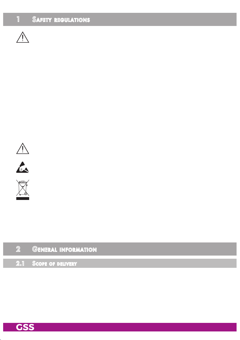
2.1 sco pe of d e lIvery
1 AV connection board
1 AV cable
1 Brief Assembly Instructions
- 3 - HAV 160
HAV 160
Page 4

2.2 mea nIng of t he sy mbols u s ed
Important note
—> General note
–
–
/
/
Optional use of the buttons
• Performing works
2.3 technIc al data
The requirements of the following EU directives are met:
2011/65/EU, 2014/30/EU, 2014/35/EU
The product fulfils the guidelines and standards for CE labelling (page 8).
Unless otherwise noted all values are specified as “typical”.
Inputs:
Audio
Impedance: .................................................................................. 47 kΩ
Audio level: ............................................................................... 0.5 V
Video
Impedance: ....................................................................................75 Ω
Video level:....................................................................................1 V
rms
pp
Connections:
Audio input: .................................................................... 8 cinch sockets
Video input: .................................................................... 4 cinch sockets
AV output: ...........................................................................
- 4 - HAV 160
26-pin
socket
Page 5

2.4 des c rIptIon
The AV connection board
signals into the modulator modules
The audio signals that have been fed in reach the AV interface via the audio
sockets (red = right-hand channel, white = left-hand channel / mono) as well
as the downstream level regulator. The video signals fed in via the video sockets (yellow) are also here. The existing signals are fed to the modulator module
via the AV interface.
HAV 160
is designed for feeding audio and video
HMM 470
and
HMS 470
.
3 InstallatIon
3.1 InstallI ng the m odule
– Observe the instructions for installing outlined in chapters 4 and 9 of the
assembly instructions STC 160.
– Assemble the AV connection board left of the corresponding modulator
module in a short, non-numbered groove.
—> The illustration shows, for example, slot 3 (modulator module) and
the slot for the add-on module (AV connection board) for installation.
B
A
• Insert the AV connection board into grooves A and B of the slot to the left
of the corresponding modulator module.
• Push the AV connection board with a little pressure into the head-end station
until they click into place.
- 5 - HAV 160
Page 6

3.2 co n n ectIng t he mo du le
Channel strip ”A“
Audio right
Audio mono / left
Video
Channel strip ”B“
Channel strip ”C“
Channel strip ”D“
C
• Using the AV cable C, connect the AV connection board to the modulator
module.
•
Connect the Cinch inputs of the AV connection board to the audio and video
signal sources via the intended cable terminals on the head-end station.
4 settIngs
4.1 aud Io leve l reg u l ato r
• If necessary, adjust the audio input level to the requirements using the level
controllers (factory setting: centre position).
Level control channel strip ”A“
Audio right
Audio left (mono)
Level control channel strip ”B“
Level control channel strip ”C“
Level control channel strip ”D“
- 6 - HAV 160
Page 7

4.2 pr o gr a m mIng th e mod ul ato r modu le
M
If a mono audio signal (white Cinch socket) is fed in, you program the cor-
responding channel strip of the connected mono modulator module to “Mono
L” (assembly instructions
HMM 470 / HMS 470
).
Bx 3A
Mono L
AUDIO
M
/
Mono L / L + R
5 fI n a l procedures
After installing the head-end station, upgrading accessories or installing mod-
ules it is necessary to tighten all cable connections, cable terminals and cover
screws in order to maintain compliance with current EMC regulations.
• Securely tighten the cable connections using an appropriate open-ended
spanner.
• Test the output level of the output collector according to the STC 160 assembly instructions and set the output level required for the cable system.
• Mount the base plate and the front cover (see STC 160 assembly instructions).
- 7 - HAV 160
Page 8

CE - Declaration of Conformity
GSS Grundig Systems GmbH • Beuthener Straße 43 • D-90471 Nuremberg
Phone: +49 (0) 911 / 703 8877 • Fax: +49 (0) 911 / 703 9210
www.gss.de/en • info@gss.de
Service: Phone: +49 (0) 911/703 2221; Fax: +49 (0) 911/703 2326; service@gss.de
Alterations reserved. Technical data E. & O.E. © by GSS Grundig Systems GmbH 002/2017
 Loading...