

GSS GSS.remote RLC 8 Assembly Instruction Manual
RLC 8
Assembly Instruction

Contents
1 Safety regulations .......................................................................................3
2 General information ....................................................................................3
2.1 Packing contents ............................................................................3
2.2 Meaning of the symbols used ..........................................................3
2.3 Technical data ...............................................................................4
2.4 Description ...................................................................................5
2.5 PC / laptop system requirements .....................................................6
2.6 Overview of the management unit ...................................................7
3 Installation ..................................................................................................8
3.1 Potential equalisation (PE) ...........................................................8
3.2 Assembling a connection cable .......................................................9
3.3 Connecting components .................................................................9
4 Installing the software on a PC or laptop ....................................................10
3.1 Key Code (Activation Code) for the software ...................................10
3.2 Installing the software ...................................................................10
5 Connecting to a network ............................................................................ 14
5.1 LAN configuration .......................................................................14
5.2 Check the configuration at the control unit of the head-end station .....16
6 Firmware update ....................................................................................... 17
7 Remote access via Internet .........................................................................18
- 2 - RLC 8
1 safety regulations
• Assembly, installation and servicing should be carried out by authorised
electricians.
• Observe
cassettes and head-end station used
tions e.g the standards
Take action to prevent static discharge when working on the device!
the safety regulations and notes in the assembly instructions for the
as well as the relevant safety instruc-
EN/DIN EN 50083 resp. IEC/EN/DIN EN 60728
2 general information
2.1 PaCk ing Co ntents
1 RLC 8
1 network cable 2 m
8 RS-232 plug (9-pin Sub D)
8 RS-232 sockets (9-pin Sub D)
1 ribbon cable (9-pin)
1 Power supply unit
1 Brief assembly instruction
.
2.2 meani ng of t h e sym b ols us e d
Important note
—> General note
• Performing works
- 3 - RLC 8

2.3 teChniCal da ta
The devices meet the following EU directives:
2011/65/EU, 2014/30/EU, 2014/35/EU
The product fulfils the guidelines and standards for CE labelling (page 30).
Connections
LAN 1000-BASE-T ............................................................. 1 RJ-45 socket
RS-232: .................................................................... 8 Sub D 9-pin plugs
for connecting up to 8 head-end stations
and/or a monitoring cassette PSCU 6000/HSCU 6000
DC socket 2,1 / 5,5 mm ............................................................1
Netzwork ports:
TCP port 60002 (alternative 35000 – 60100, 61000 – 65000)
HTML port 80
DNS port 53 UDP/TCP
Monitoring cassette PSCU 6000 / HSCU 6000
The following items are signalled:
– Level of the output signal measured via PSCU 6000 / HSCU 6000
– BIT – error rate at QAM output signals
– Present line synchronizing signal at analogous PAL output signals
– Present RDS station name at FM output signals
– Quality of the input signal (good, poor and no signal) at QPSK-PAL double
transmodulators as well as QPSK- QAM transmodulators
Remote control:
– Remote control is possible at all current cassettes and head-end stations of
the Standard- and Profi Line.
Required index levels for remote control:
PSW 1000 index level: ≥ V65
BE-Remote index level: ≥ V45
- 4 - RLC 8
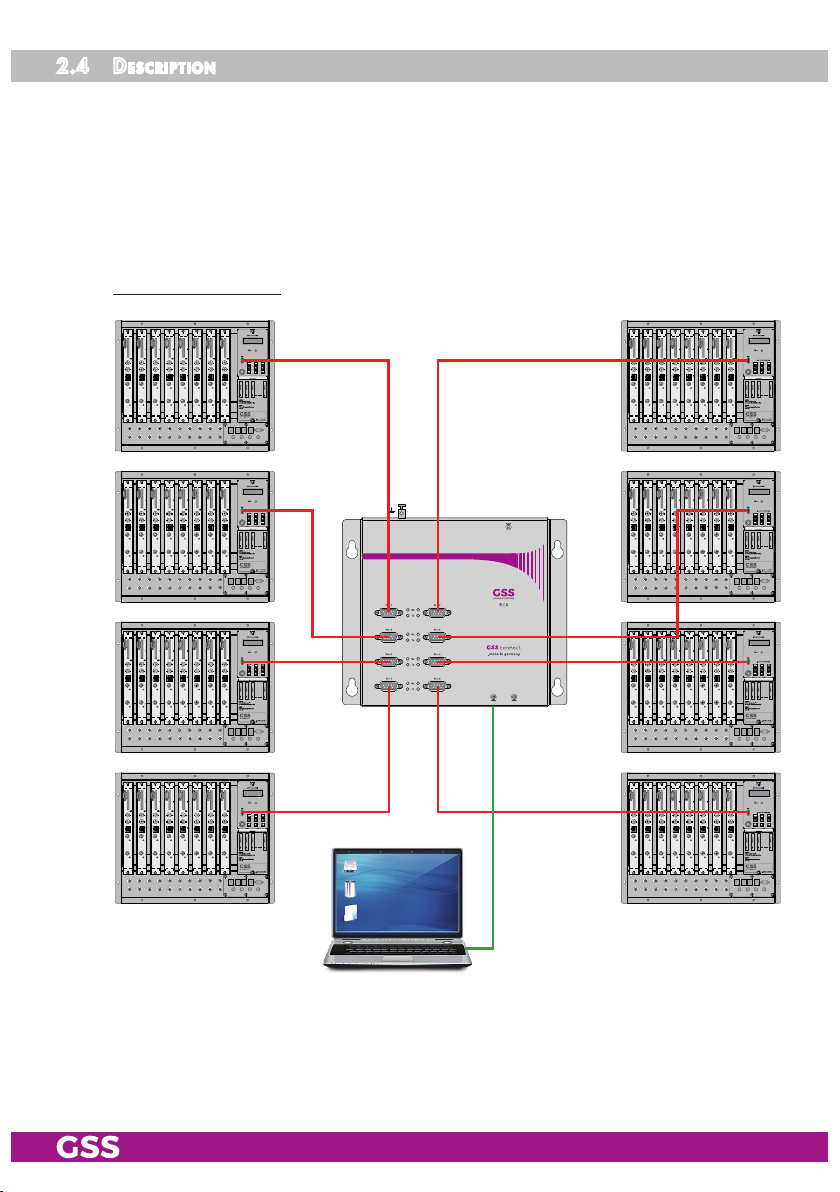
2.4 des CriPtion
The RLC 8 Management System will be connected to a PC or a network via the
LAN interface and enables communication between the PC and the connected
head-end stations (LAN <-> 8 x RS232). Therefore the Windows software
PSW 1000 ist needed.
A connection to the Internet (and thereby remote control) is possible via a
router.
Hardware concept:
- 5 - RLC 8
The basic units can be configured and remote controlled via Ethernet with
software PSW 1000.
The most current version can be downloaded from "www.mygss.eu".
A key code (activation code) is required for the activation of the PSW 1000
software.
This can be obtained from your regional authorised distributor.
The RLC 8 has 8 RS-232 interfaces (Sub D connectors/male) to connect up to
8 headend stations (control units "BE-Remote") to a PC/network. The monitoring cassette PSCU 6000/HSCU 6000 is also supported.
Error messages from the PSCU 6000/HSCU 6000 monitoring cassette can be
forwarded by e-mail.
Required index levels for remote control and remote updates:
– PSW 1000 index level: ≥ V65
– BE-Remote index level: ≥ V45
2.5 PC / l aPtoP s yste m requ irement s
System requirements for the PSW 1000 software:
– PC or laptop with a Pentium processor,
– Windows 95*/98*/ME/2000/Vista/7 (*from Internet Explorer 5 on),
– At least 32 MB RAM, at least 50 MB free space on hard drive,
– LAN interface (RJ 45 socket)
– Internet access for downloads and remote maintenance.
- 6 - RLC 8
 Loading...