

Page 1
SMCIP 401
DVB-S/S2 DVB-S
KLASSE
CLASS
GSS
Grundig SAT Systems GmbH
English
Beuthener Strasse 43
D-90471 Nuremberg
Phone: +49 (0) 911 / 703 8877
Fax: +49 (0) 911 / 703 9210
E-mail: info@gss.de
Internet: http://www.gss.de/en
Page 2

Contents
1 Safety regulations and notes ........................................................................4
2 General information ....................................................................................5
2.1 Packing contents ............................................................................5
2.2 Meaning of the symbols used ..........................................................5
2.3 Technical data ...............................................................................5
2.4 Description ...................................................................................6
Block diagram ...............................................................................6
Descrambling programmes of an existing plant .................................7
Extending an existing plant with descrambling the extended programmes ........8
General ........................................................................................9
3 Assembly ..................................................................................................10
3.1 Installing the device .....................................................................10
3.2 device overview ..........................................................................11
3.3 Connecting the device ..................................................................11
Potential equalisation (PE) .............................................................11
SAT IF Connections ......................................................................11
If a free input is available at the multiswitch: ..............................12
If no free input is available at the multiswitch: ............................12
3.4 Retrofitting a CA module ..............................................................14
3.5 Software .....................................................................................15
Software query............................................................................15
Software update ..........................................................................15
4 The control panel at a glance ..................................................................... 18
4.1 Control panel ..............................................................................18
4.2 Menu items .................................................................................18
5 Programming ............................................................................................ 19
5.1 Notes on frequency setting ...........................................................19
Level too high ..............................................................................20
Level too low ...............................................................................20
Thus, the level must be adjusted .....................................................20
5.3 Programming procedure ...............................................................21
5.4 Programming the cassette ............................................................23
Status menu ................................................................................23
Output parameter, level ................................................................24
Modulator frequency (SAT IF) ...................................................24
Output symbol rate, Spectral position, code rate (FEC) ................25
- 2 - SMCIP 401
Page 3

Input parameter ...........................................................................26
LNB oscillator frequency / control voltage .................................26
Input symbol rate ....................................................................28
Input frequency ......................................................................28
Operation with a CA module ...................................................29
Station selection .....................................................................29
Output data rate ..........................................................................31
Transport stream ID and ORGNET-ID ..............................................31
PCR Jitter ....................................................................................32
CA data packets .........................................................................32
PID monitoring ............................................................................33
CA module .................................................................................34
Factory reset ...............................................................................35
Saving data ................................................................................35
- 3 - SMCIP 401
Page 4
1 sa f e t y r e g u l a t i o n s a n d n o t e s
• This device is subject to the provisions of protection class II .
• Do not operate the device without equipotential bonding!
• The standards EN/DIN EN 50083 resp. IEC/EN/DIN EN 60728 must be
observed
• Observe the relevant standards, regulations and guidelines on the installation and operation of antenna systems.
• Observe the relevant VDE regulations.
• Do not perform installation and service work during thunderstorms.
• Assembly, installation and servicing should be carried out by authorised
electricians.
• Switch off the operating voltage of the system before beginning with assembly or service work or pull out the mains plug.
• Install the system so it will not be able to vibrate…
- in a dust-free, dry environment
- in such a manner that it is protected from moisture, fumes, splashing wa-
- somewhere protected from direct sunlight
- not within the immediate vicinity of heat sources
- in an ambient temperature of 0 °C to +40 °C. In case of the formation of
• Ensure that the device is adequately ventilated.
Do not cover the ventilation slots.
•
• Do not place any vessels containing liquids on the device.
•
•
• Avoid short circuits
• No liability is accepted for any damage caused by faulty connections or
• Test the software versions of the device and update them if necessary. The
Do not install the
Do not place anything on the device which could initiate fires (e.g. candles).
Due to the risk of fires caused by lightning strikes, we recommend that all
mechanical parts (e.g. distributor, equipotential bonding rail, etc.) be mounted
on a non-combustible base. Wood panelling, wooden beams, plastic covered
panels and plastic panels are all examples of combustible bases.
inappropriate handling.
current software versions can be found at "www.gss.de/en".
.
ter and dampness
condensation wait until the system is completely dried.
device
in cabinets or recesses which are not ventilated.
Take action to prevent static discharge when working at the device!
- 4 - SMCIP 401
Page 5
Electronic devices should never be disposed of in the household rubbish. In accordance
with directive 2002/96/EC of the European Parliament and the European Council from
January 27, 2003 which addresses old electronic and electrical devices, such devices
must be disposed of at a designated collection facility. At the end of its service life,
please take your device to one of these public collection facilities for proper disposal.
2 ge n e r a l i n f o r m a t i o n
2.1 PaCk ing Co ntents
1 SMCIP 401
1 Assembly instructions
2.2 meani ng of t h e sym b ols us e d
Important note
—> General note
• Performing works
2.3 teChniCal da ta
The devices meet the following EU directives:
2006/95/EC, 2004/108/EC, 2011/65/EU
The product fulfils the guidelines and standards for CE labelling (page 36).
Unless otherwise noted all values are specified as "typical".
RF input DVB-S2
Frequency range: ....................................................... 950 … 2150 MHz
Level range: ............................................................ 60 dBμV … 80 dBμV
DVB-S modes: .....................................DVB-S 1/2 , 2/3 , 3/4 , 5/6 , 7/8
DVB-S2 modes: .......QPSK 1/2 , 3/5 , 2/3 , 3/4 , 4/5 , 5/6 , 8/9 , 9/10
8PSK 3/5 , 2/3 , 3/4 , 5/6 , 8/9 , 9/10
16APSK 2/3, 3/4, 4/5, 5/6, 8/9, 9/10
32APSK 3/4, 4/5, 5/6, 8/9, 9/10
Symbol rate: .....................................................QPSK: 1 … 53 MSymb/s
8PSK: 1 … 45 MSymb/s
16APSK: 1 … 35 MSymb/s
32APSK: 1 … 28 MSymb/s
- 5 - SMCIP 401
Page 6
Maximum net data rate per tuner ...............................................72 Mbit/s
DiSEqC
*DiSEqCTM is a trademark of EUTELSAT
TM*
: ............................ 1.1 (16 Satellites with 4 levels, max. 60 mA)
RF output DVB-S
Frequency range: ....................................................... 950 … 2250 MHz
Level range: ............................................................ 48 dBμV … 95 dBμV
(Adjustable attenuation in 47 1dB steps)
DVB-S modes: .....................................DVB-S 1/2 , 2/3 , 3/4 , 5/6 , 7/8
Symbol rate: .....................................................QPSK: 1 … 45 MSymb/s
FEC:............................................................ 1/2 , 2/3 , 3/4 , 5/6 , 7/8
Maximum data rate. ........................................................... 72573 kbit/s
Rolloff: ...........................................................................................0.25
Connections
SAT inputs: ............................................................................. 4 F sockets
Loop input (LNB): .................................................................... 1 F socket
SAT output: ............................................................................ 1 F socket
Micro USB socket: ......................................................for software update
Common Interface: .......................1 (several channels can be descrambled)
Power Supply
Mains voltage: .................................................... 220–240V~, 50/60 Hz
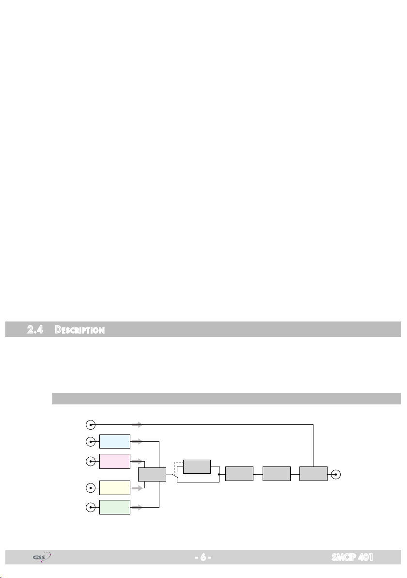
2.4 des CriPtion
The transmodulator converts channels from up to 4 DVB-S/DVB-S2 transpond-
ers into one DVB-S transponder.
Using an adequate CA module a scrambled channel can be descrambled.
bloCk d i agram
- 6 - SMCIP 401
LNB IN
SAT IN "A"
SAT IN "B"
SAT IN "C"
SAT IN "D"
Tuner "A"
Tuner "B"
Tuner "C"
Tuner "D"
MUX
CA-Modul
CA module
DVB-S
Modulator
47 dB
Attenuator
Combiner
SAT Output
Page 7
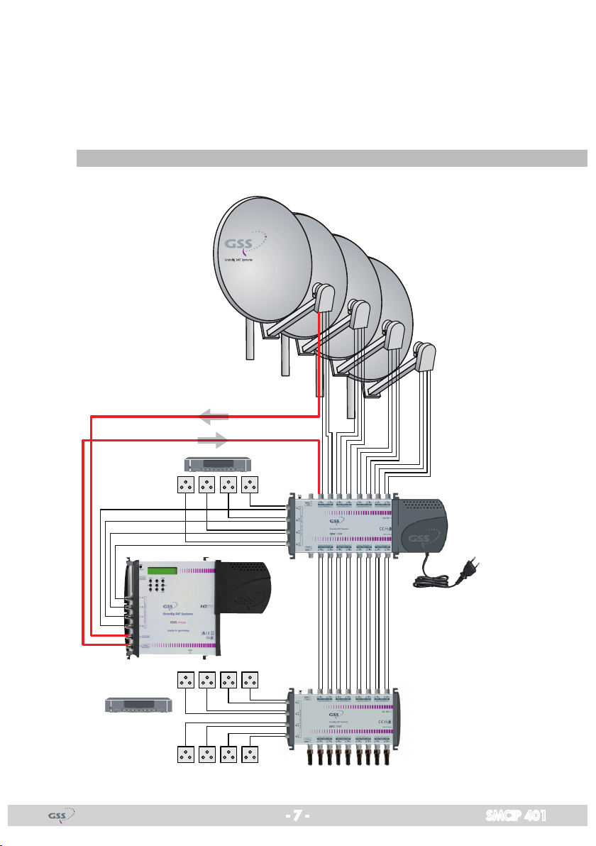
The 4 tuners receive their input signal from the outputs of a multiswitch. If no
further input is free for the converted signal at the multiswitch, the corresponding satellite band can be multiplexed with the converted signal via the LNB
input and then feed into the multiswitch. There are two fields of application for
the device:
desCrambli ng Pro g r a m m es of an e xisti ng Plant
Receiver
- 7 - SMCIP 401
Page 8
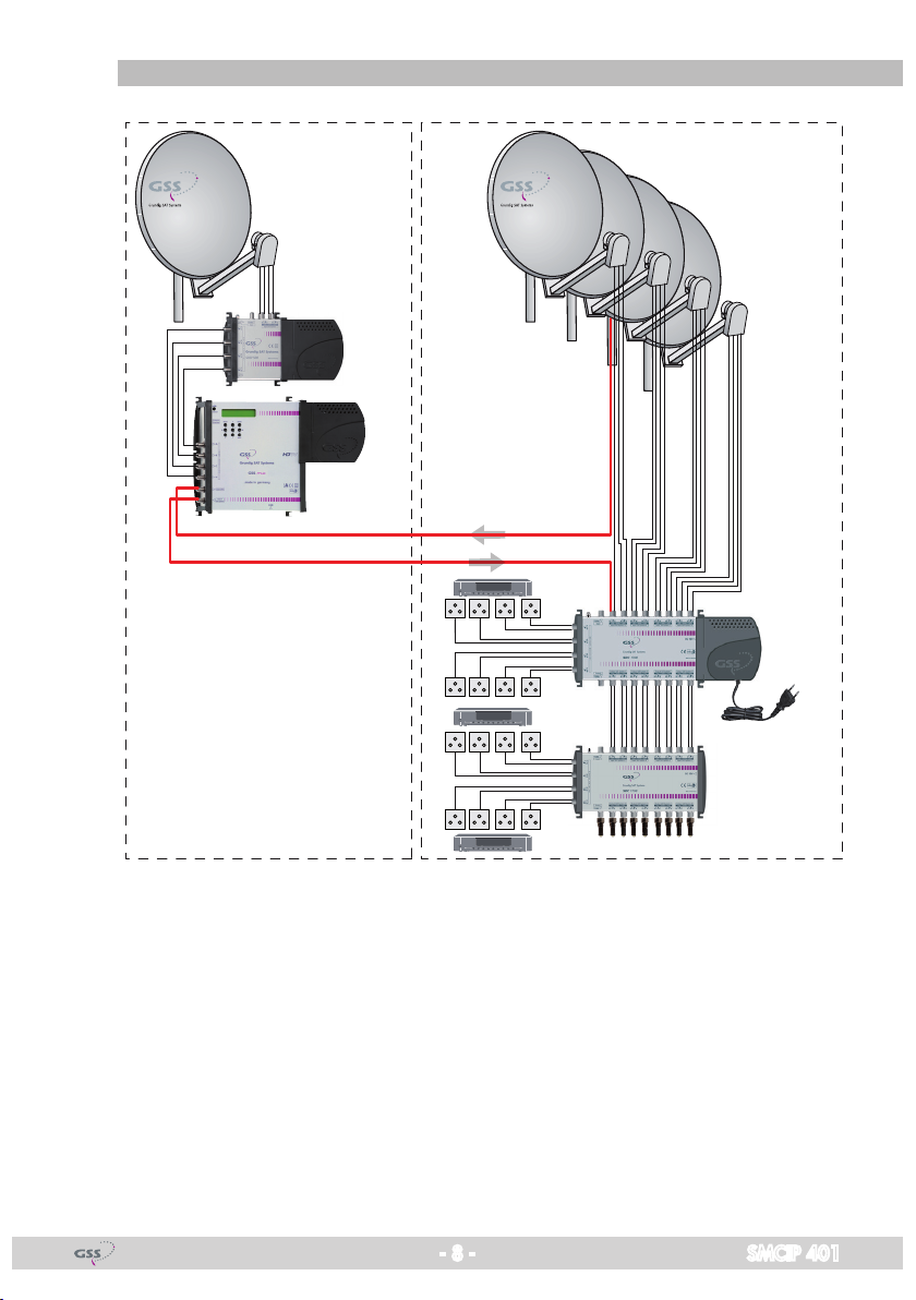
exte nding a n exis t i ng Pl ant wit h desC ra m b ling t he exte nded P rogrammes
Current plantExtension
The converted transponder must be fed into the SAT IF range with the same
frequency range.
- 8 - SMCIP 401
Page 9

general
As signal source the corresponding Tuner can be selected.
The letters abcd on the display provide an indication of the input signal quality:
DVB-S =>
ABcD
DVBS
V 2
In this example tuners A, B and D have reception (capitals), tuner C has no
reception (lower case).
The output signal (new transponder) can be fit in a gap of a SAT IF range.
Therefore the corresponding range must be connected to the LNB input. At the
RF output the SAT IF range with fit in "new" transponder is present.
- 9 - SMCIP 401
Page 10
3 as s e m b l y
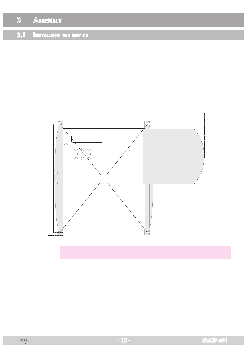
3.1 installi ng the d e viCe
– Ensure the device is mounted so it will not be able to vibrate. Avoid, for
example, mounting the device onto a lift shaft or any other wall or floor
construction that vibrates in a similar way.
• Position the device so that the distance on the left side, below and above is
minimum 20 cm.
• Fasten the
216 mm
227 mm
device
at the slots 1.
175 mm
300 mm
1
—> Use mounting material suitable for the wall properties.
- 10 - SMCIP 401
Page 11
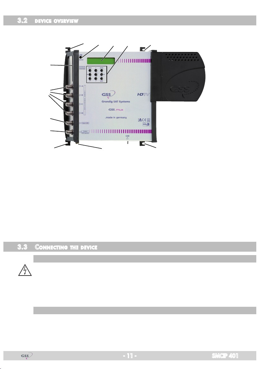
3.2 devi Ce ov ervie w
6
8
9
0
41 13 5
21 1
1 Assembling slots 2 PE connection terminal
7
3 Display 4 Display contrast control
5 Operating buttons 6 Slot for CA module
7 Micro USB socket (update) 8
9
3.3 Con neCting the d e v iCe
Pote ntial equa lisation (Pe)
•
sat if ConneCti ons
• Connect the SAT IF inputs
Loop through input (LNB) 0 SAT IF output
Equalise the potential (PE) in accordance with IEC/EN/DIN EN 60728.
Connect the PE connection terminal 2 to a PE rail (supplied by customer)
using a PE wire (Cu 4 mm2 - 6 mm2).
8 to the outputs of a multiswitch.
SAT
tuner inputs A…D
- 11 - SMCIP 401
Page 12

if a f ree in Put is available at t he multisw itCh:
• Connect the SAT IF output 0 to a free input of the multiswitch.
• Connect the device to the mains power supply.
Receiver
if no f ree i nPut i s avai la ble at th e multiswit C h:
—> In this case the new transponder should work at a unused frequency.
• Remove the connection cable of the multiswitch input, via which the fre-
quency range (low or high band) is connected, in which the converted transponder works and connect it to the LNB input 9 of the device.
- 12 - SMCIP 401
Page 13

—> If you would like to integrate the device to an existing plant, now
first you should connect it to the mains and perform all settings
(page 21). Therefore especially observe the notes on frequency setting (page 19) and level setting (page 20).
• If the programming is finished connect the SAT IF output 0 to the now free
input of the multiswitch.
—> The converted transponder will be output at the SAT IF output to-
gether with the SAT IF range, which is fed in to the LNB input and
then fed in again to the multiswitch.
• Connect the device to the mains power supply.
- 13 - SMCIP 401
Page 14

3.4 retr o fitting a Ca module
The device is equipped with a common interface. It allows you to connect a
CA module for various scrambling systems and service providers. Scrambled
channels can only be descrambled with a CA module suitable for the scrambling system and the corresponding smart card. The smart card contains all
the information for authorisation, descrambling and subscription.
Caution
– Any changes made by programme providers to the structures in the pro-
gramme data might impair or even prevent this function.
– When working with the CA module, please read the corresponding operat-
ing manual from the respective provider.
• Insert the smart card into the CA module so that the chip C on the smart
card A faces the thicker side (top) of the CA module B.
• Insert the CA module into the slot D with the top side of the CA module
facing the rear side of the device.
• Push the CA module without canting into the guide rails of the CA slot D
and contact it to the common interface.
CD AB
- 14 - SMCIP 401
Page 15

3.5 soft ware
softwa r e query
When the
device
is switched on, the two-line LC display shows the software
version.
softwa r e uPdate
The operating software of the device can be updated via the micro USB socket
using a PC and the software "BE-Flash".
You can find the current operating
software, the software "BE-Flash" and the current assembly instructions on the
website "www.gss.de/en".
• Unpack the downloaded ".zip file", which contains the new device software and the "BE-Flash" application.
• Open the device manager of the PC.
• Note down the already existing USB Serial Ports (e.g. COM3).
• Connect the
Micro USB socket via a commercially available USB cable with
the PC.
—> Windows installs the necessary driver automatically. This can take
several minutes. Do not disconnect the USB connection during installation!
• Use the device manager to identify the COM port, which is assigned to the
SMCIP401.
- 15 - SMCIP 401
Page 16

—> In this example – the new added port COM4.
• Start the "BE-Flash" application (BEflash.exe) and select the corresponding
interface (COM port).
• Click on button ,
• Select the .hex file you had unpacked before and click on button .
• Click on button .
- 16 - SMCIP 401
Page 17

—> The update progress is displayed.
• Close the "BE-Flash" application.
• Uninstall the COM port driver from the device manager after the update is
finished successfully!
—> Active the COM port driver (in this example COM4).
Select in menu Action or via the context menu
the menu item Uninstall.
• Disconnect the USB connection.
- 17 - SMCIP 401
Page 18

4 th e C o n t r o l P a n e l a t a g l a n C e
4.1 Co n trol Pane l
The key pad on the device is used to scroll through the menus step-by-step:
MODE
BACK
< / >
+ / –
MULTI selects presets
S saves all entries
F
4.2 me nu ite m s
scrolls forward through the menus
scrolls backward through the menus
select parameters/submenus
set values, initiate actions
"function"
Programme the
two-line display of the control unit then shows the menus.
The parameters and functions to be set are underlined.
Select the following main menu items:
– Output – level:
Output frequency
Symbol rate, FEC
– Input:
LNB oscillator frequency, DiSEqC
Input symbol rate
Input frequency
Station selection
– Data rate
– TS/ONID
– PCR
– CA mode
– CA module
– Factory reset
cassette
using the buttons on the control unit of the device. The
- 18 - SMCIP 401
Page 19

5 Pr o g r a m m i n g
5.1 not e s on f requenC y setti ng
If you fit in the "new" transponder to an existing SAT IF range, you have to set
the output frequency to a gap (or the beginning/end) of the spectrum.
—> To ensure that an existing gap will not occupied by the satellite op-
erator, you can cut the upper end of the frequency spectrum in order
to generate your own gap by using a filter to the LNB input 9. Our
filters lower the frequency spectrum from 1920 MHz ("GF1920")
resp. 2120 MHz ("GF2120") on to -30 dB.
0
GF1920
0
GF2120
-30
-60
dB
MHz
190015001000
-30
-60
dB
2100 MHz15001000
• Feed the SAT IF range, in which you would like to insert the "new" transponder, into the device via LNB input 9.
• Connect a SAT IF spectrum measurement device to output 0.
• Graph the spectrum which is present at the device output 0 with a measuring instrument and adjust the output frequency of the "new" transponder to
the gap.
—> In order to get the receiving frequency which must be set, you have
to add the corresponding LNB oscillator frequency (e.g. 9750 MHz
low band, 10600 MHz high band) to the SAT IF frequency of the
transponder.
- 19 - SMCIP 401
Page 20

5.2
not e s on l e vel se tting
Equalize the output level of the device (menu "OUTPUT") to the levels of the
other transponders, in order not to overdrive downstreamed multiswitches/
amplifiers.
level t o o high
level t o o lo w
th us, t he lev el mus t be a djus t ed
• Graph the spectrum which is present at the device output 0 with a measuring instrument and equalize the output level of the "new" transponder to the
spectrum.
- 20 - SMCIP 401
Page 21

5.3 Progr am ming Pr o Cedure
Ein / On
ABCD = Signal
Tuner
A / B / C / D
DVB-S =>
abcd
DVB-S
– 5 d B
0 … -47 dB
DVB-S
Tuner A
DVBS
V 2
OUTPU T
INPUT
OK =>
Bedienhinweise
"blättert" Menüs vorwärts
"blättert" Menüs rückwärts
wählen die Eingabeposition
wählt Untermenü
stellen Werte ein
speichert alle Eingaben
wählt Presets
spezielle Funktionen
1 zeigt die Eingabeposition
=>
2200…20000MHz
MULTI: 10600/9750
1000…56000ksymb/s
MULTI: 22000/27500
1236 MHz
DVB-S
45000
A
10600 MHz
A
27500
A
11837 +0.7
FREQDVB-S
SYMBO L
POS 7 /8
LNB
SYMBO L
8PSK 2/3
FREQ
CN 9
Operating Hints
scrolls forward through the menu
scrolls backward through the menu
select the enter position
selects a submenu
set values and triggers actions
saves all entries
selects presets
special functions
1 shows the enter position
950…2250 MHz
5000…45000 kSymb/s
POS/ NEG
1/2, 2/3, 3/4, 5 /6, 7 /8
off
off / _ _ _ _
h / l (high / low)
H / V (horizontal / vertical)
A,B / 0…F hex (0…15)
T (Ton/sound) / D (DiSEqC)
Bx 4A /B
10600 MHz
Beispiel: DAHh bedeutet
DiSEqC (D) -Position 10 (A),
Horizontal (H) high (h)
Example: DAHh means
DiSEqC (D) position 10 (A),
horizontal (H) high (h)
B
A
Page 22
LNB
DAHh
–/+/X (aus/ein/entschlüsseln)
–/+/X (off/on/descramble)
Sender wählen / select station
DVB-S
OVER
DVB-S
0x000 1
DATARATE
28 / 72.5
TS/ON ID
0x010 0
Das E rste
MULTI: alle ein/aus
MULTI: all on/off
aktuell benötigt/max.
current needed/max.
OVER = Overflow
01/06A TV
+
*
= verschlüsselt/scrambled
*
- 21 - SMCIP 401
Page 22

DVB-S
OVER
DATARATE
28 / 72.5
aktuell benötigt/max.
current needed/max.
OVER = Overflow
*
= verschlüsselt/scrambled
Sender wählen / select station
–/+/X (aus/ein/entschlüsseln)
–/+/X (off/on/descramble)
DVB-S
0x000 1
TS/ON ID
0x010 0
Tuner
A / B / C / D
2200…20000MHz
MULTI: 10600/9750
1000…56000ksymb/s
MULTI: 22000/27500
MULTI: alle ein/aus
MULTI: all on/off
POS 7 /8
45000
DVB-S
Tuner A
INPUT
OK =>
LNB
off
A
10600 MHz
SYMBO L
8PSK 2/3
A
27500
FREQ
CN 9
A
11837 +0.7
01/06A TV
*
+
Das E rste
POS/ NEG
1/2, 2/3, 3/4, 5 /6, 7 /8
Bx 4A /B
10600 MHz
LNB
DAHh
Beispiel: DAHh bedeutet
DiSEqC (D) -Position 10 (A),
Horizontal (H) high (h)
Example: DAHh means
DiSEqC (D) position 10 (A),
horizontal (H) high (h)
off / _ _ _ _
h / l (high / low)
H / V (horizontal / vertical)
A,B / 0…F hex (0…15)
T (Ton/sound) / D (DiSEqC)
DVB-S
origi nal
original / dejitter
DVB-S
204
DVB-S
PID C heck VidCA =>
off / Vid / All
DVB-S
Defau lts
DVB-S
S => S TORE
PCR
CA-MO DE
*) Die angezeigte Information ist abhängig
vom verwendeten CA-Modul.
The information displayed is dependent
on the CA module used.
FACTORY
=>
MEMORY
Data –> CA
204/188 Bit
nur mit CA-Modul/
onlywith CA module
DVB-S 01/0 5
Infor matio n *)
Werkeinstellung
aufrufen
invoke factory defaults
Einstellung speichern
store factory defaults
MENU
DVB-S
S TORE
Page 21
A
STORE
FACTORY
=> S
Page 21
B
- 22 - SMCIP 401
Page 23

5.4 Pro g r a m m i n g the Cass et te
—> Pressing the MODE button for longer than 2 seconds cancels the
programming procedure. This takes you back to the "Status menu"
from any menu. Any entries that have not been saved are reset to
the previous settings.
—> Entries in the menus can be saved by pressing the S key. You are
taken back to the "Selecting the cassette" menu item.
—> The cursor position for settings is shown by "_".
• Switch on the device (connect the mains plug to a mains socket).
status menu
—> The display shows the software version (e.g. V 2).
DVB-S =>
abcd
DVBS
V 2
The letters abcd on the display provide an indication whether tuners A…D are
locked to input signals:
DVB-S =>
ABcD
DVBS
V 2
—> In this example …
… the tuner A,B and D have locked an input signal / a transponder,
… tuner C has not locked an input signal.
Input signal locked => capitals
Input signal not locked => lower case
• Press the MODE button.
—> The "Output parameter" – "OUTPUT" menu is activated.
- 23 - SMCIP 401
Page 24

outPut Pa ra m e ter, level
In this menu you adjust the output level of the modulator and you have access
to the submenus for the modulator configuration.
DVB-S
– 5 dB
OUTPUT
=>
• Using buttons +/– adjust the desired level (0dB … –47dB).
—> Therefore observe page 20.
—> In order to skip the "output parameter" settings press button MODE.
The "input parameter" menu – "INPUT" is activated (page 26).
• Press the > button.
—> The "modulator frequency" submenu – "FREQ" is activated.
modulat o r fre q u enCy (sat if)
In this menu you adjust the output frequency of the modulator.
FREQDVB-S
1236 MHz
• Using buttons </> to select the cursor position for the frequency setting.
• Using buttons +/– to adjust the desired frequency (950 MHz … 2250 MHz).
—> Therefore observe page 19.
—> You must add the corresponding LNB oscillator frequency (e.g.
9750 MHz low band, 10600 MHz high band) to the SAT IF frequency, in order to get the receiving frequency, which must be set at
a receiver.
• Press the MODE button.
—> The "Output symbol rate" submenu – "SYMBOL" is activated.
- 24 - SMCIP 401
Page 25

outPut sym bol rat e, sPeCtr al Pos ition, Code r ate (feC)
In this menu you can set the symbol rate, the Spectral position and the code
rate of the output signal.
—> Modulation schemes such as QPSK transmit multiple bits simultane-
ously. These are referred to as symbols. In addition to the user data
flow which transmits video and audio information, error correction
bits are transferred. The FEC number states the ratio of user bits to
the complete transmitted bits.
DVB-S
45000
SYMBOL
POS 7/8
Symbol rate:
• Use the </> buttons to position the cursor under the digit of the displayed
symbol rate (5000…45000 kSymb/s).
•
Press +/– to set the respective digit of the symbol rate.
• Repeat the procedure by the quantity of the digits to be set.
Spectral position – inverting the user signal
For exceptional cases and "older" digital receivers, the spectral position of the
user signal can be inverted "NEG"
. The default setting is
"POS".
• Use </> to place the cursor under "POS".
• Use +/– to set the spectral position to "NEG".
Code rate (FEC):
—> During a transmission data can be lost or changed. To recover this
data redundancy is added to the signal to be transmitted (forward
error correction – FEC). The factor of the quantity of redundancy
contained in the bits transmitted is called code rate.
Using the setting "C7/8" you can get the highest output data rate at
lowest error correction.
• Use </> to place the cursor under "7/8
".
• Use +/– to set the required code rate ("1/2", "2/3", "3/4", "5/6", "7/8").
• Press the MODE button.
—>
Return to the
- 25 - SMCIP 401
"output parameter" main menu
– "OUTPUT"
.
Page 26

• Press the MODE button.
—> The "input parameter
" menu – "INPUT" is activated.
inPut Paramet er
In this menu you select the tuner for which you would like to do the input set-
tings in the related submenus.
DVB-S
Tuner A
—> In order to skip the input parameter settings, press button
"output data rate" menu is activated
—> "OK" indicates a present input signal.
INPUT
OK =>
(page 31).
MODE
. The
• Using the buttons +/– to select the desired tuner ("A"…"D").
•
Press the >
button.
—> The "LNB oscillator frequency, control voltage" – "
activated.
LNB
" submenu is
lnb o s C illat o r fre q u e nCy / Contro l vo ltage
In this menu set the oscillator frequency of the LNB used and, if necessary, a
LNB control voltage.
A
10600 MHz
LNB
off
LNB oscillator frequency:
• Using button MULTI you can toggle the customary standard values
9750/10600 MHz.
• For deviating values use the buttons </> to position the cursor under the
digit to be set for the displayed oscillator frequency.
• Press the +/– buttons to enter the corresponding digit of the oscillator frequency of the LNB used.
• Repeat the procedure by the quantity of the digits to be set.
- 26 - SMCIP 401
Page 27

DiSEqC commands:
• In order to set a DiSEqC command, position the cursor under "off" using
button >.
• Using buttons +/– to select the desired control voltage.
"abcd" are place-holders for the following setting options:
A
10600 MHz
LNB
abcd
Place-holder Value Description
a _ No function
T Sound
D DiSEqC
b _ No function
A, B Sound A or B
0…F Hexadecimal value for DiSEqC command
0…15
c: H Horizontal polarisation
V Vertical polarisation
d: h High-Band
l Low-Band
Example: DAHh means DiSEqC position 10, Horizontal high
—> The control voltage only serves to control multiswitches and is not
suitable for power supply of upstreamed components (maximum
load 65mA).
—> GSS Multiswitches must be triggered by the following DiSEqC co-
mands:
Input group A —> DiSEqC command D0
Input group B —> DiSEqC command D1
Input group C —> DiSEqC command D2
Input group D —> DiSEqC command D3
Example: In order to trigger input group B for horizontal polarisa-
tion and high band D1Hh must be set.
• Press the MODE button.
—> The "Input symbol rate / DVB mode" submenu – "SYMBOL" is activated.
- 27 - SMCIP 401
Page 28

inPut s ymbo l rat e
In this menu you set the symbol rate of the desired transponder in kSymb/s.
A
27500
SYMBOL
8PSK 2/3
The symbol rates of the satellite transponders can be found in the current chan-
nel table of the satellite operator, in various satellite magazines and in the
Internet.
• Using button MULTI you can toggle the customary standard values
22000/27500 kSymb/s.
• For deviating values use the buttons </> to position the cursor under the
digit to be set for the displayed symbol rate.
• Press the +/– buttons to enter the corresponding digit of the desired symbol
rate.
• Repeat the procedure by the quantity of the digits to be set.
—> If an input signal is present, its DVB mode (e.g. 8PSK) and the FEC
factor (e.g. 2/3) is displayed.
• Press the MODE button.
—> The "Input frequency" sub menu – "FREQ" is activated.
inPut f requen Cy
In this menu you set the input frequency of the desired transponder in MHz.
A
11837 +1.8
Once the RF receiver has synchronised to the input signal, any offset to the
FREQ
CN 9
target frequency is displayed in MHz, e.g. "– 1.8".
If a question mark "?" appears in the second line of the display, there is no
input signal present. In this case check the configuration of the antenna system
as well as the preceding settings of the device
- 28 - SMCIP 401
Page 29

• Use </> to position the cursor under the digit of the frequency displayed to
be set.
•
Press +/– to set the respective digit of the input frequency needed.
• Repeat the procedure by the quantity of the digits to be set.
• Set the frequency offset shown in the display (e.g. "– 1.8") to less than
1MHz ("± 0.x") by varying the input frequency using the +/– buttons.
Signal to noise ratio:
"CN …" indicates the current signal to noise ratio, in order to estimate the
quality of the input signal.
• Press the MODE button.
—> The "station selection" submenu – e.g. "TV" is activated.
oPerat i o n wit h a Ca module
In order to descramble scrambled channels a corresponding smart card is
needed.
The channels to be descrambled are set in submenu "station selection".
stati on sele C tion
In this menu you select the stations (services), which shall be inserted into the
"new" transponder.
Herein you select which scrambled station should be descrambled using an
adequate CA module.
A TV +
Das Erste
—> All stations from the channel strip will be read, and then displayed
with name and station type.
—> If no station is found, the following message will appear in the dis-
play: "FILTER no Service". In this case, check the configuration of
the antenna system, as well as the previously adjusted settings for
the device.
- 29 - SMCIP 401
01/06
Page 30

—> The display shows e.g.:
Das Erste
Meaning of the indicators in the example:
"A" Tuner "A"
"TV" TV channel type
" + "
"
01/06" The 1st of 6 stations is being displayed.
"
Das Erste
Further possible terms displayed:
"RA" Radio channel type
For radio stations, the back
" – "
" * " The star means that the TV or radio station selected is
" X "
—> If a service number (e.g. "131") appears instead of "TV" or "RA",
this indicates that an unnamed station or an undefined data stream
is being received.
The currently
" Station name
connected TV or test receiver is darkened.
The selected station is
stream.
scrambled. To enable the station, the CA module and
the appropriate smart card of the station provider are
required.
The selected station will be descrambled.
A TV * + 01/06
selected
station is switched on.
ground of the screen of the
not included in the transport
• Use the </> buttons to call up the stations in sequential order, then use
+/– to
activate (indicated by " + ") or to deactivate them (indicated by " – ").
—> If a station is scrambled (indication "*"), in this menu you select
whether it should be descrambled using an adequate CA module.
• Press button + twice to descramble a station (indication "X").
01/06A TV X +
• Press the MODE button.
—>
Return to the
"input parameter
" main menu – "INPUT"
.
• Press the MODE button.
- 30 - SMCIP 401
Page 31

—> The "Output data rate" – "DATARATE" main
menu is activated
.
outPut data r ate
This menu shows the output data rate defined by the output parameter settings
and the current needed output data rate in MBit/s.
DVB-S
OVER
DATARATE
28 / 72.5
28: The current needed output data rate.
72.5: Maximum output data rate (dependent on the settings of symbol rate
and the FEC).
If the station filter is set correctly, the current needed data rate is lower than
the maximum data rate. The value fluctuates, since the data rates of individual
stations are dynamically modified by the broadcasters.
—> Is the current needed data rate higher than the maximum data rate
"OVER" appears in the display. In this case correct the output parameter settings (pages 25…)
or
the settings of the station selection
(page 29).
DVB-S
OVER
DATARATE
75 / 72.5
• Press the MODE button.
—> The "Transport stream ID and ORGNET-ID" – "TS/ONID" main
menu is activated.
tr an sPort s tream id and orgnet-id
If a completely new, additional transponder is generated, IDs (ORGNET-IDs)
must be assigned to it, in order that a station search of connected SetTopBoxes
can be performed faultlessly.
DVB-S
0x0001
- 31 - SMCIP 401
TS/ONID
0x0100
Page 32

• Use the </> buttons to position the cursor under the digit of the hexadecimal
number of the TS-ID to be set.
•
Press +/– to set the respective digit of the hexadecimal number.
• Repeat the procedure by the quantity of the digits to be set.
• Using the > button place the cursor under the digit of the hexadecimal
number of the ON-ID to be set.
•
Press +/– to set the respective digit of the hexadecimal number.
• Repeat the procedure by the quantity of the digits to be set.
—>
By pressing the
< button you return to the
setting of the
TS-ID.
• Press the MODE button.
—> The "
PCR-Jitter
" – "PCR" main menu is activated.
PCr ji t t er
In this menu, you can, if PCR jitter causing interference, activate a jitter reduc-
tion.
• Use the buttons +/–
DVB-S
original
to activate (indicated by "dejitter"), resp. deactivate
PCR
(indicated by "original") the jitter reduction.
—>
The selection "dejitter" leads to significantly better jitter measurements, but may cause disruptions in older receivers.
• Press the MODE button.
—> The CA "
CA data packets
" – "CA-MODE" menu is activated.
Ca data PaCkets
In this menu you can adapt the size of the data packets, which are transmitted
to the CA module (depending on the CA module).
DVB-S
204
- 32 - SMCIP 401
CA-MODE
Page 33

• Use +/– buttons to set the size of the data packets (188/204 Bit).
—>
AlphaCrypt modules use 204 bit datapackets, Neotion modules
188 bit.
• Press the MODE button.
–> The "PID monitoring" – "CA" main
menu is activated
.
Pid m o n itori ng
In this menu you can switch off the PID monitoring and call up a menu for the
settings of the CA module (dependent on the CA module).
DVB-S
PID Check VidCA =>
—> If there is no CA module inserted, this menu has no function.
—> The factory default is video PID monitoring ("Vid"). Optionally all
PIDs can be monitored.
If particular PIDs are not descrambled the CA module is reset. Ad-
ditionally dropouts may occur if several stations are descrambled.
To prevent this the PID monitoring can be switched off.
• Use the +/– buttons to select …
– "off", to switch off the PID monitoring,
– "Vid", to monitor only video PIDs or
– "All", to monitor all PIDs.
• Use the > button to activate the menu of the CA module
—> Access to this menu is only possible with installed CA module and
inserted smart card.
- 33 - SMCIP 401
Page 34

Ca mo du le
The menu varies according to which CA module you are using. For this rea-
son, please refer to the operating manual of your particular CA module. The
relevant information is shown in the display of the device. This may appear as
a fixed display or as scrolling text according to display capabilities.
DVB-S
PID Check onCA =>
—> The display shows e.g.: 01/05 MENU
Meaning of the indicators:
"
01/05
" The first of five menu items is activated.
"
MENU
" The menu of the CA module is activated.
DVB-S 01/05
Information *)
MENU
For the explanation of further details please use the operating instructions of
the CA module used.
• Use the +/– buttons to activate the menu desired.
• Press the > button to activate the menu.
• Use the +/– buttons to select the function desired.
• To set the CA module use the </> and +/– buttons.
—> By pressing the MODE button you can cancel the settings in the
menu of the CA module and are returned to the "PID monitoring" –
"CA" menu.
• All settings are saved by pressing the S button.
—>
You will returned to the
"PID monitoring" – "CA" menu
.
• Press the MODE button.
—> The "Factory reset" – "FACTORY Defaults" main menu is activated.
- 34 - SMCIP 401
Page 35

faCtor y res et
In this menu you can reset all settings to the factory defaults.
DVB-S
Defaults
• Press the > button.
—> The factory defaults are invoked
—> By pressing the MODE button, you will be returned to the menu item
"Output settings" without
• Press the S button.
—> The factory defaults are saved
The display shows "STORE"
—> Back to
sav i ng data
FACTORY
=>
"Status menu"
DVB-S
STORE
(page 23).
DVB-S
S => STORE
MEMORY
FACTORY
=> S
.
invoking the factory defaults
.
(page 24).
• All programmed data is saved by pressing the S button.
—> The settings are saved
The display shows "STORE"
—> Back to
"Status menu"
—> By pressing the MODE button, you will be returned to the menu item
"Output settings" without
- 35 - SMCIP 401
.
(page 23).
saving the settings
(page 24).
Page 36

Declaration of CE conformity
Service:
Phone: +49 (0) 911 / 703 2221 • Fax: +49 (0) 911 / 703 2326 • Email: service@gss.de
Grundig SAT Systems GmbH • Beuthener Straße 43 • D-90471 Nürnberg • Germany
Alterations reserved. Technical data E. & O.E. © GSS GmbH V2/25072014
 Loading...