


GLC 100
Ethernet over Coax
KLASSE
CLASS
GSS
Grundig SAT Systems GmbH
English
Beuthener Strasse 43
D-90471 Nuremberg
Phone: +49 (0) 911 / 703 8877
Fax: +49 (0) 911 / 703 9210
E-mail: info@gss.de
Internet: http://www.gss.de/en

Contents
1 Safety regulations and notes ........................................................................4
2 General information ....................................................................................6
2.1 Packing contents ............................................................................6
2.2 Meaning of the symbols used ..........................................................6
2.3 Technical data ...............................................................................6
2.4 Description ...................................................................................7
Traditional LAN network .................................................................7
EoC network .................................................................................7
3 Assembly ....................................................................................................8
4 Overview of GCL 100 .................................................................................. 9
5 Installation and commissioning ..................................................................10
5.1 Define the approach ....................................................................10
Preparatory works for private networks via… ..................................10
… Security buttons ..................................................................10
… Configuration software .......................................................10
5.2 Installation ..................................................................................11
5.3 Application examples ...................................................................12
SAT IF distribution via multiswitch ..................................................12
Feed in via return channel capable antenna socket .....................12
Feed in via the input of the SAT multiswitch ................................13
Head-end station .........................................................................14
Feed in via return channel capable antenna socket .....................14
Feed in at the output of the head-end station ..............................15
Broadband cable ........................................................................16
Feed in via return channel capable antenna socket .....................16
Feed in at the output of the broadband cable modem .................17
5.4 Commissioning ............................................................................18
Indicators ...................................................................................18
Power-LED .............................................................................18
EoC-LED ................................................................................18
LAN-LEDs ...............................................................................18
Standby mode .............................................................................19
Factory defaults ...........................................................................19
Security button ............................................................................19
6 Configuration ............................................................................................ 20
6.1 Security function ..........................................................................20
- 2 - GLC 100

Private EoC network with encryption: .............................................20
Connect the first two devices: ...................................................20
Integrate further devices: .........................................................21
7 Configuration Software ..............................................................................22
7.1 Installation ..................................................................................22
7.2 Operation ..................................................................................23
Main menu .................................................................................23
Rename a device ....................................................................24
Enter the device password .......................................................24
Quality ..................................................................................25
Data rate (Mbps) ....................................................................25
MAC address ........................................................................25
Add an external modem ..........................................................25
Firmware update ....................................................................26
Create a private network ..............................................................26
Diagnostics .................................................................................28
Info ............................................................................................29
8 Drill template ............................................................................................30
- 3 - GLC 100
1 safety regulations and notes
cm
10cm
5
cm
5
+40
0
+5
ATTENTION: IN ORDER TO REDUCE THE RISK OF ELECTRIC SHOCK, DO
NOT OPEN THE CABINET. INSIDE THE CABINET THERE ARE NO PART
WHICH CAN BE REPAIRED BY THE USER. IF NECESSARY CONTACT QUALIFIED SERVICE TECHNICIANS.
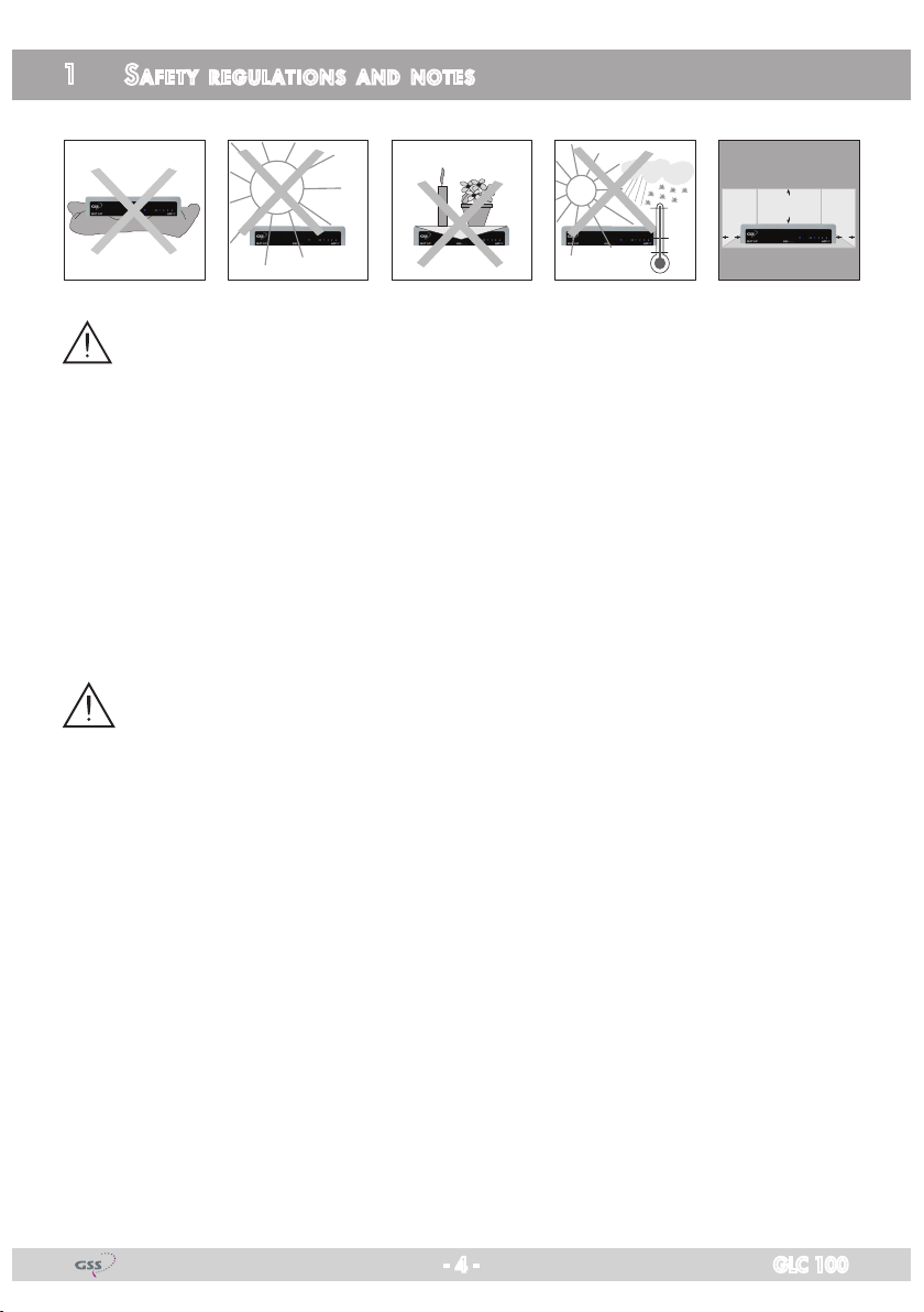
Safety precautions:
This device was manufactured according to the specifications of international
safety standards. For your own protection, you should read the safety instructions carefully before using your new device.
The manufacturer assumes no liability for damages caused by improper han-
dling or by ignoring the safety precautions.
• This device is designed to transmit data signals via coaxial cables. Any other
use is expressly prohibited.
• Operate the device only with the supplied AC cable.
• When setting up the device, make sure the mains socket is easily accessible.
• If the device is subject to a sudden change in temperature, for example
when brought in from the cold to a warm room, let it stand for at least two
hours before you connect it to the mains supply.
• Do not expose the device to any moisture. The digital receiver is designed
for use in dry rooms. If you do use it outdoors, please ensure that it is protected from moisture, such as rain or splashing water.
• Place the device on a flat, solid surface for use.
• Make sure the device is adequately ventilated. Make sure that the left and
right, a free space of about 5 cm, 10 cm above is available to allow the air
to circulate freely and the device does not overheat. Never cover the vents
with newspapers, tablecloths, curtains, etc..
• Do not place anything on the device which could initiate fires (e.g. candles)
or contain liquids.
• Do not use the device close to heating units or in direct sunlight.
- 4 - GLC 100

• The device should be operated at temperatures of 0 ºC to 40 ºC. Use the
device only in a moderate climate, not in tropical conditions.
• Avoid short circuits!
• Thunderstorms are a danger to all electrical devices. Even if the device is
switched off, it can be damaged by a stroke of lightning to the mains or the
antenna cable. Therefore always disconnect the device from the mains and
from the antenna unit during a thunderstorm or extended shutdowns (e.g.
holidays).
• Never open the device under any circumstances. No liability is accepted
for damage caused by faulty connections or inappropriate handling of the
device.
The devices meet the EU directives 2006/95/EC, 2004/108/EC and
2011/65/EU.
The product fulfils the guidelines and standards for CE labelling
Electronic devices should never be disposed of in the household rubbish. In
accordance with directive 2002/96/EC of the European Parliament and the
European Council from January 27, 2003 which addresses old electronic and
electrical devices, such devices must be disposed of at a designated collection
facility. At the end of its service life, please take your device to one of these
public collection facilities for proper disposal.
- 5 - GLC 100
2 general information
2.1 PaCking Cont ents
GLC 100
Power supply cable Network cable
Termination resistor Brief assembly instructions
2.2 meani ng of t h e sym b ols us e d
Important note
—> General note
• Performing works
2.3 teChniCal da ta
The devices meet the following EU directives:
2006/95/EC, 2004/108/EC and 2011/65/EU
The product fulfils the guidelines and standards for CE labelling (Page 31).
Unless otherwise noted all values are specified as "typical".
Frequency ranges
EoC in-/output ............................................................... 2…862 MHz
Data signal ..................................................................... 2…68 MHz
TV output .................................................................... 85…862 MHz
Through loss ...............................................................................<0.5 dB
Minimum output level 1…30 MHz ............................................. 100 dBμV
Minimum output level 30…68 MHz ............................................. 90 dBμV
Network ................................................................max. 64 EoC Modems
Gross data rate .......................................................................500 Mbps
Net data rate ..........................................................................230 Mbps
Range ................................................................................. max. 700 m
Modulation ..........................................4096/1024/256/64/16/8-QAM
QPSK, BPSK, ROBO Modulation
Encryption ........................................................................... 128 bit AES
Ethernet Interface .....................................................10/100/1000 Mbps
Network standard ...................................... IEEE 1901, IEEE802.3, 802.3u
Connectors (TV/EoC) ...................................................................... 2 x F
- 6 - GLC 100
Connectors (LAN) ..................................................................... 2 x RJ 45
Router
Smart-TV
Router
Smart-TV
Ethernet over Coax
LEDs ............................................................. Power /EoC /LAN 1/LAN 2
Switching Power supply ..........................................110-230 V~50/60 Hz
Power consumption ...............................................................max. 5.5 W
Dimensions (WxHxD) in mm ........................................... 145 x 33 x 82,5
Operating temperature .......................................................... 0°C ~ 40°C
Corresponds to the standards ................................EN50083-2, EN55022,
EN50412, EN60950-1
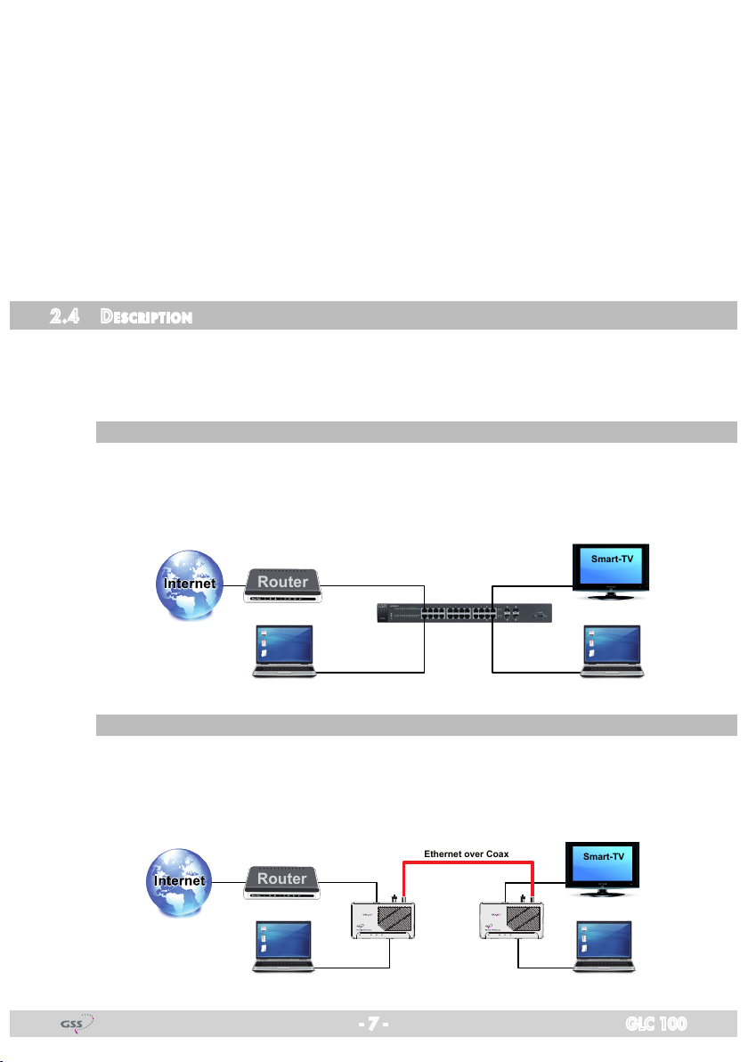
2.4 des CriPtion
The GLC 100 is an "Ethernet over Coax" (EoC) modem which allows the
feeding in of IP data signals (e.G. from the Internet, IPTV etc.) into an existing
coaxial distribution system (in star or tree distribution).
tr a d itiona l lan n et work
All components of a traditional LAN network are connected via network ca-
bles in star distribution. Starting from a switch, cables must be routed to all
components.
eoC n etwork
At an EoC network an existing coaxial antenna network is used for transmit-
ting the signals. Here both star, and tree distribution is possible. The data is
fed in and out via EoC modems.
Power EoC LAN1 LAN2 Power EoC LAN1 LAN2
- 7 - GLC 100

The EoC modems communicate in peer to peer mode (P2P).
In the factory default settings, each EoC modem can communicate with each
other modem in the network.
The advantage of "Ethernet over Coax" is that it is not necessary to lay new
network cables and that there is no expenditure for additional installation.
The data is transmitted through the low-attenuation return channel, frequency
range of 2…68 MHz. Depending on the quality of the coaxial cable, transmission distances of up to 700 m can be realized.
The feeding in is done via the terrestrial input of the SAT multiswitch capable
for return-channel signals, via the terrestrial input of the antenna distributor
structure or via an antenna socket capable for return-channel signals (OR 02,
OR 09, OR 11, OR 15, OR 20, ORS 13 DC) in the distribution network.
An access to the Internet or other transmitted IP data are then available on
each return channel capable antenna sockets.
Two networkable devices can be connected to one EoC modem. The IP net-
work can be extended to up to 64 EoC devices.
Ex factory all devices connected to a EoC modem can communicate with each
other. Data is exchanged, network games are transmitted or a centralized
network printer can be accessed. For the monitoring of houses, rooms etc., an
IP camera can be operated via an EoC modem.
At multiple-user antenna networks, encrypted private networks can be config-
ured (see page 20).
If e.g. you would like to provide Internet access in hotel rooms, although a
network connection to the Internet must be possible, but not between the different rooms. To achieve this, a so-called master / slave mode can be set. If
you have any need for this, please contact your sales partner (www.gss.de ->
Sales partners) because the network must be configured specifically for this
purpose.
3 assembly
The device is operated primarily as a stand mounted unit (4 rubber feet).
4 brackets for wall mounting are provided on the bottom. With 2 screws each
different orientations are possible. A drill template can be found on page 30 of
this manual.
- 8 - GLC 100
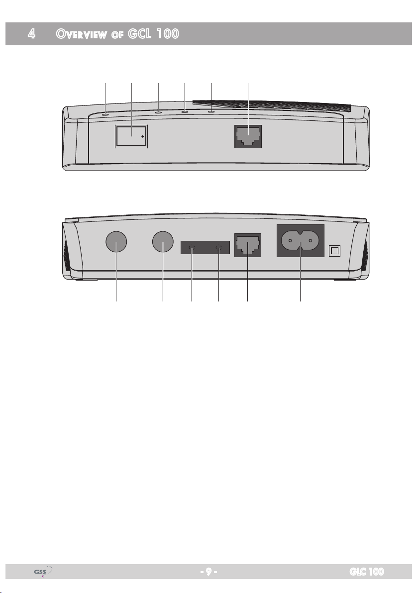
4 over view of gCl 100
1 2 3 4 5 6
OFF ON
Power
EoC TV Reset Security LAN1
7 8 9 0 ! @
LAN2
110-230V~
50-60Hz
1
Power LED
2 Power switch (ON/OFF)
3 EoC LED
4 LAN1 LED
5 LAN2 LED
6 LAN2 socket
7 EoC socket
8 TV socket
9 Reset button
0 Security button
!
@
- 9 - GLC 100
LAN1 socket
Socket for mains cable
5 installation and Commissioning
5.1 define t h e aPP roaC h
Dependent on the local conditions, several approaches are possible.
In order to avoid unnecessary movements, before installation you should de-
fine how you want to configure the EoC network.
If the antenna system is also used by other participants, you can build up your
own private EoC network.
By securing your EoC network, you protect all information sent via the network
against inadvertent access. This is particularly important in multi-family homes,
office buildings, schools and other buildings.
There are two possibilities to secure your EoC network.
Take a few minutes to read first the parts "Configuration" from page 20 on and
"Configuration software" from page 22 on.
Pre Par ato ry w o rks f o r Pri vate n et works via…
… se C urity b u t tons
If you would like to build up a private network with the help of the security but-
tons, it is easier if you first create the private network key for two devices via a
short coax cable and then successively transfer it into the further devices. Then
you only need to install the configured devices in the appropriate rooms.
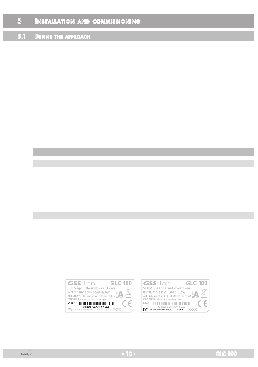
… Co n figurat ion so ft war e
If you want to build a private network using the Configuration software, you
should first create a list of the MAC addresses and their corresponding passwords of the EoC modems, in order to assign a private network name to
all modems – centrally from one modem using the Configuration software
(page 22). The MAC address and the corresponding password can be found on
the sticker on the bottom of the device.
- 10 - GLC 100
5.2 installat ion
All components of the coaxial distributor structure must support the return chan-
nel frequency range of 2…68 MHz.
In the simplest case, you establish a connection via two EoC modems (see
description page 7).
• Connect up to two network devices (e.g. router, PC, smart TV etc.) to the
LAN sockets 6/! of one EoC modem.
• Connect the "EoC" F socket 7 to the already existing antenna distribution
network.
Dependant on the local conditions there are several possibilities to feed the
IP data into the existing antenna network structure. Via the passive terrestrial
input of a SAT multiswitch resp. at the output of a head-end station or via the
CTV socket of a return channel capable antenna socket in the distribution
network. A TV which was connected to this socket must then be connected
to the TV socket of the EoC modem 8.
• Accordingly connect further EoC modems to the antenna distribution network.
—> Broadband networks:
The EoC transmission is done in the return channel frequency range
of 2…68 MHz, which is also used for Internet services in broadband networks. For this reason, it must be ensured that the EoC sig-
nal does not cause disturbances in the cable network via the point
of interconnection (POI) – e.g. by using a commercially available
high-pass filter at the output of the CATV amplifier.
Observe the examples on the following pages.
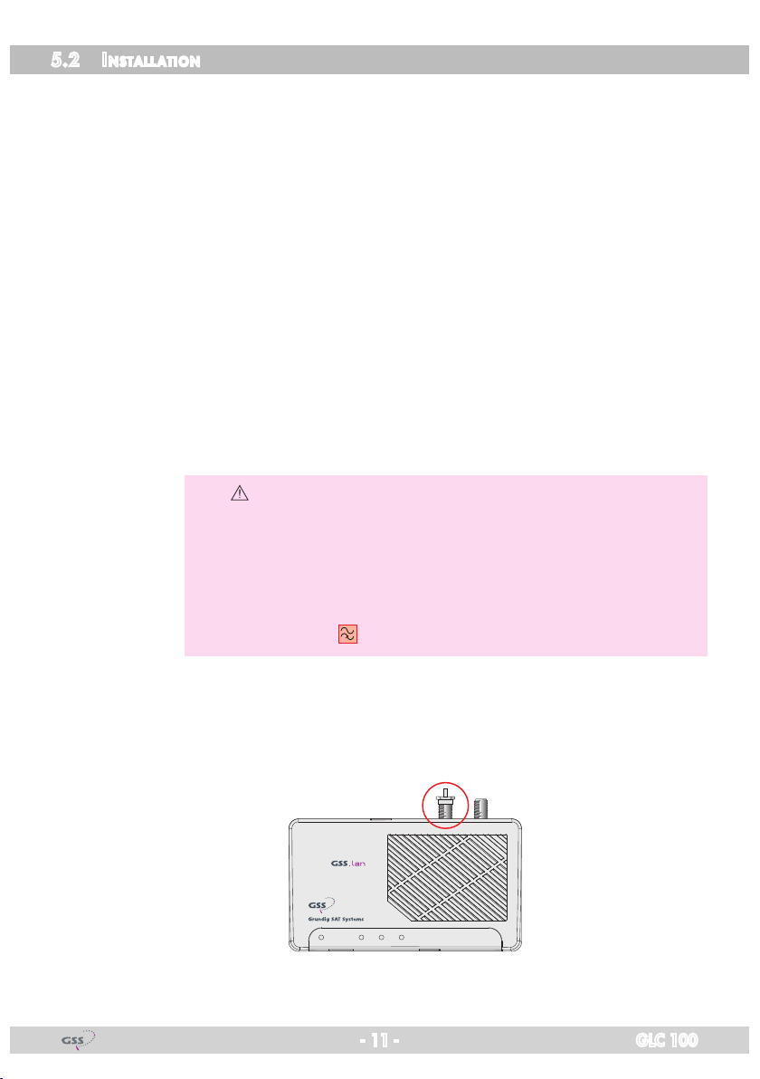
If the TV socket of an EoC modem is not used, it must be terminated with the
attached termination resistor!
Power EoC LAN1 LAN2
- 11 - GLC 100
5.3 aPP liCat i on examPl e s
Router
Receiver
Receiver
Receiver
Receiver
QRS13DC
QRS13DC
TV
TVTVTV
QRS13DC
QRS13DC
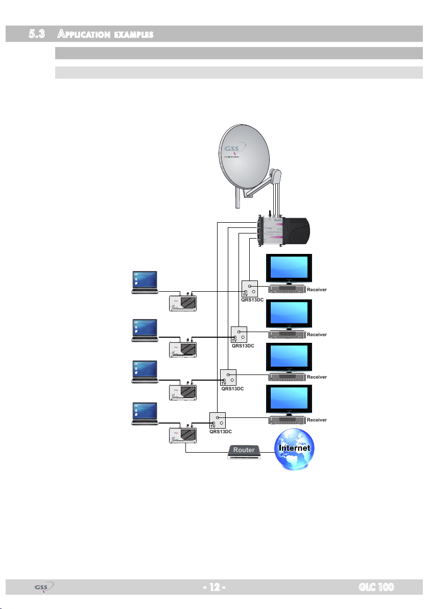
sat if distr i b ution v i a multiswi tCh
fe ed in v ia re turn C hannel C a Pab le an tenna s o Cket
The feed in of the IP signals e.g. is done via a return channel capable antenna
socket.
Power EoC LAN1 LAN2
Power EoC LAN1 LAN2
Power EoC LAN1 LAN2
Power EoC LAN1 LAN2
When feeding in IP data via the antenna socket, the terrestrial input of a SAT
multiswitch, if not used for other purposes, must be connected to a terminating
resistor of 75 Ω (e.g. FT 75).
- 12 - GLC 100
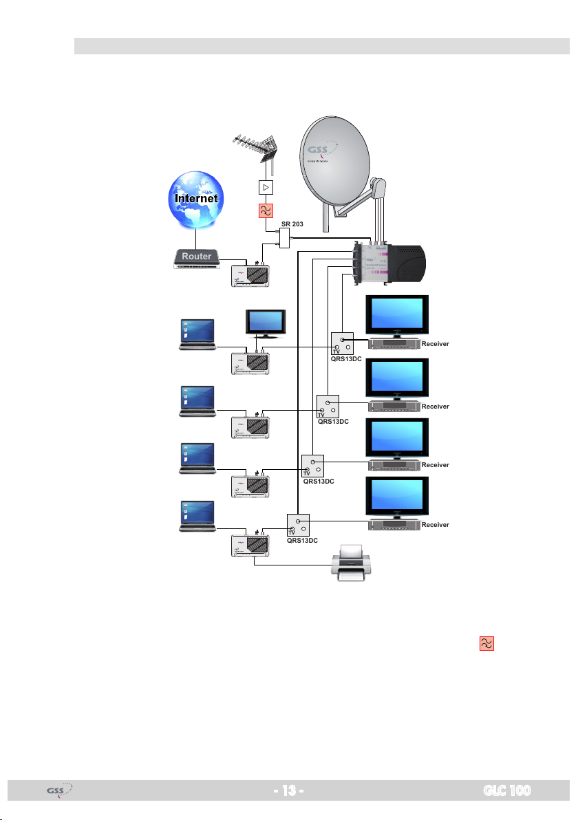
fe ed in v ia th e inPut of th e sat mu lti s w itCh
Router
Receiver
Receiver
Receiver
Receiver
QRS13DC
SR 203
QRS13DC
TV
TV
TV
TV
QRS13DC
QRS13DC
The feed in of the IP signals e.g. is done via the return channel capable ter-
restrial input of the SAT multiswitch.
Power EoC LAN1 LAN2
Power EoC LAN1 LAN2
Power EoC LAN1 LAN2
Power EoC LAN1 LAN2
Power EoC LAN1 LAN2
If the IP data and the DVB-T, FM or CATV signal are fed in using the terrestrial
input, the signals are interconnected via a two-way splitter (e.g. SR 203) operated in reverse direction. A commercially available high-pass filter , which
blocks the return channel range, must be inserted in the coaxial line of the
terrestrial signals.
- 13 - GLC 100

head -end stat ion
Router
HbbTV
+
DVB-C/T
HbbTV
+
DVB-C/T
HbbTV
+
DVB-C/T
HbbTV
+
DVB-C/T
OR…
OR…
OR…
OR…
fe ed in v ia re turn C hannel C a Pab le an tenna s o Cket
The feed in of the IP signals e.g. is done via a return channel capable antenna
socket.
Power EoC LAN1 LAN2
Power EoC LAN1 LAN2
Power EoC LAN1 LAN2
Power EoC LAN1 LAN2
A commercially available high-pass filter , which blocks the return channel
range, must be inserted in the coaxial supply line from the head-end station.
- 14 - GLC 100
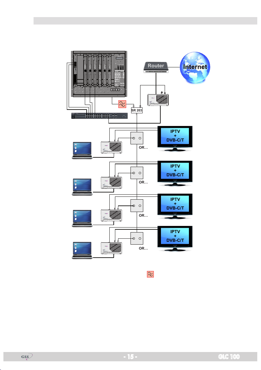
fe ed in at t h e outP u t of t h e head -e nd stat ion
IPTV
+
DVB-C/T
IPTV
+
DVB-C/T
IPTV
+
DVB-C/T
IPTV
+
DVB-C/T
Router
SR 203
OR…
OR…
OR…
OR…
The feed in of the IP signals e.g. is done via a two-way splitter (e.g. SR 203)
operated in reverse direction at the output of the head-end station.
Power EoC LAN1 LAN2
Power EoC LAN1 LAN2
Power EoC LAN1 LAN2
Power EoC LAN1 LAN2
Power EoC LAN1 LAN2
A commercially available high-pass filter , which blocks the return channel
range, must be inserted in the coaxial supply line from the head-end station.
- 15 - GLC 100

bro adband Cable
Router
HbbTV
+
DVB-C
HbbTV
+
DVB-C
HbbTV
+
DVB-C
HbbTV
+
DVB-C
POI
fe ed in v ia re turn C hannel C a Pab le an tenna s o Cket
The feed in of the IP signals e.g. is done via the return channel capable an-
tenna socket.
Power EoC LAN1 LAN2
Power EoC LAN1 LAN2
Power EoC LAN1 LAN2
Power EoC LAN1 LAN2
The EoC transmission is done in the return channel frequency range of
2…68 MHz, which is also used for Internet services in broadband networks.
For this reason, it must be ensured that the EoC signal does not cause disturbances in the cable network via the point of interconnection (POI) – e.g. by
using a commercially available high-pass filter at the output of the CATV
amplifier.
- 16 - GLC 100

fe ed in at t h e outP u t of t h e bro adban d Cable modem
Cable
Router
HbbTV
+
DVB-C
HbbTV
+
DVB-C
HbbTV
+
DVB-C
HbbTV
+
DVB-C
SR 203
CTV
EoC
LAN
POI
The feed in of the IP signals e.g. is done via a two-way splitter (e.g. SR 203)
operated in reverse direction at the output of the broadband cable modem.
Power EoC LAN1 LAN2
Power EoC LAN1 LAN2
Power EoC LAN1 LAN2
Power EoC LAN1 LAN2
Power EoC LAN1 LAN2
The EoC transmission is done in the return channel frequency range of
2…68 MHz, which is also used for Internet services in broadband networks.
For this reason, it must be ensured that the EoC signal does not cause disturbances in the cable network via the point of interconnection (POI) – e.g. by
using a commercially available high-pass filter at the output of the CATV
amplifier.
- 17 - GLC 100

5.4 Com mission ing
As soon as all connections have been established, the EoC devices can be
switched on by pressing the power switches 2 and the connected devices
(PC, notebook etc.) can be booted up.
indiC ato rs
Po w er-led
The Power LED 1 flashes for a short time and lights continuously as soon as
the device is ready for operation. It flashes in standby mode (page 19).
eoC-led
The EoC LED 3 light up green as soon as a connection to an other device is
established.
During data traffic the EoC LED flashes.
If the EoC LED light red, the attenuation of the coaxial network is too high.
In this case check the coaxial network resp. short the distance between the
devices.
—> If no EoC connection can be established…
– check whether a coaxial connection exists.
– check whether all components of the coaxial distributor struc-
ture support the return channel frequency range of 2…68 MHz.
– position the EoC modem closer to each other (shorter coaxial
wire).
– After having activated the security function (page 20), make sure
that all EoC modems use the same network key.
– If the problem occurs after modification of the network key
(page 20), restore the factory setting on each device. Afterwards, you can generate the key again.
lan-leds
The LEDs LAN 1/2 (4/5) light up if connections to connected devices are
established.
During data transfer the LEDs are flashing.
- 18 - GLC 100

standby mode
After some minutes without data transfer, an EoC modem switches into stand-
by mode. The Power LED flashes.
—> The standby mode is automatically terminated as soon as a connect-
ed device starts a data communication, or if the modem is switched
off and on again.
—> During standby mode the reset button and the security button are out
of order.
faCt o ry d efa u lts
Using the Reset button 9 the EoC modem can be reset to the factory default
setting.
• Remove the cover from the button.
• Hold the reset button depressed for one second using a bent up paper clip,
in order to reset the device to the factory defaults.
—> If you press the Reset button less than one second or for more than
two seconds, the factory settings are not restored.
—> The reset button does not work in standby mode (page 19).
seC urity b utton
Using the Security button 0 you can…
– delete the network key or
– generate a private network.
• Remove the cover from the button.
The further procedure is described below (security function page 20).
—> The Security button does not work in standby mode (page 19).
- 19 - GLC 100

6 Configuration
An EoC network consists of two or more (max. 64) EoC modems using the
same network key.
In an existing antenna system with several participants, all devices can con-
nect to each other (factory default).
6.1 seCuri t y fun Ction
If the antenna system is also used by other participants, you can build up your
own private EoC network.
By securing your EoC network, you protect all information sent via the network
against inadvertent access. This is particularly important in multi-family homes,
office buildings, schools and other buildings.
There are two possibilities to secure your EoC network:
– Using the Security button 0, you can generate a random network key in
order to built a private network with encryption.
—> Please refer to the procedure described below.
—> The key functions of a GLC 100 W modem (with WiFi function)
are different to that of a GLC 100. For each type observe the corresponding assembly instruction.
– Define a network name for your EoC network with the help of the configura-
tion software (page 22, download from http://www.gss.de).
Pri vate eo C netwo rk wi th en CryPti on:
Make sure that the devices are not in Standby mode! The power LED must light
continuously.
• Using a bent up paper clip, delete the network key by pressing the security
button 0 on the rear side of the EoC device for more than 10 seconds (until
the power LED becomes off). Carry out this step for all devices that should
be integrated in a private network.
Con neCt t h e firs t two d e v iCes:
• Using a bent up paper clip, hold the Security button of your EoC device de-
pressed for approx. one second. According to the "release" of the Security
button the Power LED starts flashing.
• Within the next two minutes press the Security button on the next EoC mo-
dem for approx. one second. According to the "release" of the Security
- 20 - GLC 100

button the Power LED starts flashing. A new network key between the two
EoC modems is generated and the devices establish a connection.
—> If you press the Security button less than one second or for more
than two seconds, no new network key is generated.
• Check the LEDs on the EoC devices. The Power LEDs must flash during the
connection establishment of the devices. Wait for approx. one minute while
the EoC devices get connected with each other. As soon as the procedure
is finished, the power LEDs are again permanently lit. If the Power LED is
not flashing after having pressed the Security button, you have pressed the
button for a too short or long time. Try it again and press the Security button
for one second. If the EoC LEDs are not lit on both EoC devices, the EoC
devices are not connected. In this case repeat the steps in this section.
inte g r ate furt h e r devi Ces:
• Hold the Security button of any EoC device of the private network depressed
for approx. one second. According to the "release" of the Security button
the Power LED starts flashing.
• Within the next two minutes press the Security button on the next EoC mo-
dem for approx. one second (its network key must be deleted before). According to the "release" of the Security button the Power LED starts flashing.
The network key of the first EoC modem is transferred to the device without
network key, a connection is established.
—> If no EoC connection can be established…
– Reset devices which can not establish a connection to factory
defaults (page 19), delete the network key again and try again
to integrate the device to your private network.
– Establish the connection using the configuration software which
can be downloaded under http://www.gss.de. The operation
of the configuration software is described from page 22 on.
- 21 - GLC 100

7 Configuration software
With the Software "GSS.lan configuration" EoC modems are indicated in a
network, network names are assigned and private and secured networks are
created (128 Bit/AES Encryption).
The network name "HomePlugAV" represents a public network. The EoC mo-
dems are shipped with the "HomePlugAV" as the default network name.
With the software "GSS.lan configuration" a firmware update of the EoC
modem is possible. Thus, EOC devices can always be updated to the current
status.
In general, multiple networks can be set up in a coax distribution network.
Through the network name or network key, the modems are assigned to a
network.
7.1 insta llat ion
• Unzip the software package after downloading from www.gss.de.
—> When installing "GSS.lan configuration" software WinPcap library
V4.1.2 is installed. Already installed other versions of the WinPcap
library must be uninstalled before.
• Start the "Setup.exe" file.
• Follow the instructions in the Setup Wizard.
—> If an older version of the software is found on your PC, first you
should uninstall it.
- 22 - GLC 100

7.2 oP e r ati on
• Start the "GSS.lan configuration" software.
main m e n u
The main menu displays all EoC modems, which are connected to the network
and are "active" (which are not in standby mode).
At the upper section "Local device on your computer", the modem, which is
connected to your PC, is displayed. If no locally attached modem is detected,
this will be indicated above the "Connect" button.
—> If no connection can be established to the locally connected EoC
modem, the firewall of the PC should be checked (Network Threat).
The software scans the local network at intervals and detects the modems
which are "active". This "active" EoC modems are displayed in the lower sec-
tion of the screen (section for external devices).
Above the section for external devices is ...
– on the left the total number of modems which are connected to the same
network and
– on the right the AutoScan status.
In menu "Info" the AutoScan function can be switched on and off (page 29).
- 23 - GLC 100
Using the "Scan" button, an instant search for external modems is performed.
For all modems that are displayed in the lower section, the following informa-
tion is available: Device name, password, quality, data rate and MAC address. If no external modem is detected, this field remains empty.
rena me a d eviCe
In the "Device Name" column, the default device name of a modem is dis-
played. The device name can be changed, either by clicking the "Rename"
button or by directly clicking on the name in the row.
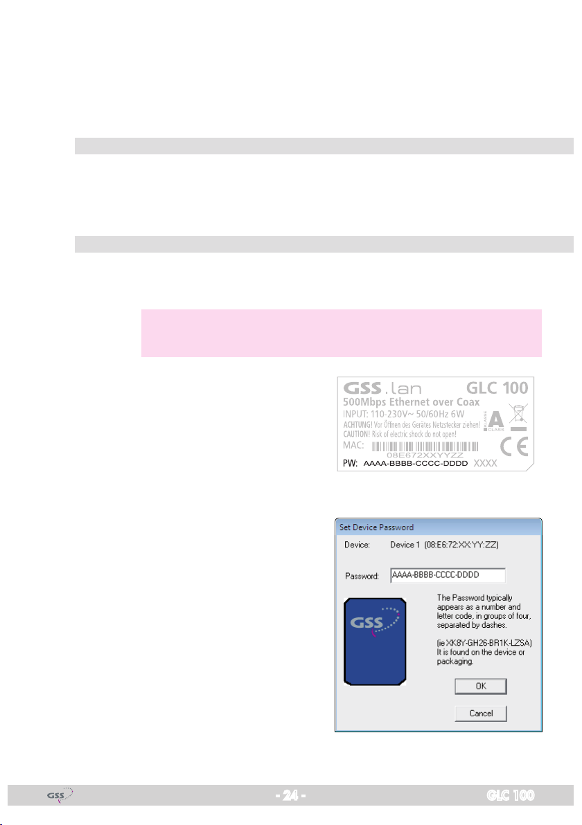
ent er th e deviC e Pa sswo rd
By default the Password column is blank. Here you can enter the device pass-
word using button "Enter Password".
—> The password is necessary for function "Set Local Device Only" in
menu "Privacy" (page 26).
The password is printed on the type la-
bel of the EoC modem. The password
consists of numbers and letters in groups
of 4.
• Select the appropriate modem at the
lower section of the main menu.
• Click on button "Enter Password" to
open the "Set Device Password" window.
• Enter the password and confirm with
"OK".
The password is now checked and con-
firmed in accordance. After that, the
password will be displayed in the "Password" column of the main menu.
- 24 - GLC 100
Qua l it y
In the "Quality" column, a bar display informs about the link quality from the
external modem to the local modem. The quality depends on the attenuation
in the distribution network.
data r ate (mbPs)
In the "Rate" column the current transfer rate between the external and local
EoC modem is displayed. The quality depends on the attenuation in the distribution network.
maC addres s
In the "MAC Address" column the MAC address of the external EoC modem
is displayed.
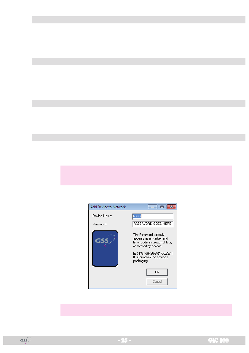
add a n exter nal m odem
With this function, you can add more EoC modems to the network of the con-
nected EoC modem.
—> While the device is added, it must be connected to the power sup-
ply and be ready for use.
• Click on button "Add" to open the "Add Device to Network" window.
• Enter a device name and the device password.
—> The password is printed on the type label of the EoC modem.
- 25 - GLC 100

• Click the "OK" button. It may take several seconds until the new modem is
added to the network.
fi rmwa r e uPd ate
You can use the "GSS.lan configuration" software to update the firmware of
the EoC modem that is locally connected to the PC. The latest PIB and NVM
firmware files are available on www.gss.de for download.
• Click the "Upgrade Firmware" button in the main menu. Then click the
"Browse" button and select the downloaded .nvm and .pib files.
• Start the firmware upgrade with button "OK".
The firmware of the modem connected to the PC is updated.
The EoC modem automatically performs a reset.
Cre ate a Pri vate n et work
In the "Privacy" menu, you can create a private, encrypted network and select
the modems, which shall be added to the network.
—> All EoC modems are shipped with the default network name
HomePlugAV.
- 26 - GLC 100

• In input field "Private Network Name" enter any network name, which
should basically consist of a string without spaces.
—> By entering "HomePlugAV" as the network name or by click-
ing the "Use Default (public network)" button, the public network
"HomePlugAV" is restored.
—> If another network name than HomePlugAV is entered, in the main
menu the network is displayed as private.
Basically, devices with the same network name can communicate.
For a network name, a network key is generated. Thus, several private networks can be constructed, which are secured by their own
network key. A network is defined by a common network key.
—> "Unknown Network Name" is displayed when a private network
has been created using the security buttons, because the security
button directly generates a network key (and no network name).
Thus, a number of private networks that have been created over the
security keys, are distinguished in the configuration software, only
by the displayed "members".
• Transfer the network name with button ...
– "Set Local Device Only" only to the modem, which is locally connected
to your PC, or
– "Set All Devices" to all modems, the device password is entered.
Using button "Set All Devices", the private network name can be assigned to
the local connected modem as well as simultaneously to all modems whose
device password has been entered in the main menu, so that they belong to
the same network. You will see a dialogue screen that indicates whether this
operation was successful. For devices, whose device password is not entered,
this operation is invalid.
After entering a private network name, all modems that are still in the "public"
network ("HomePlugAV") are no longer displayed. This communication of the
local modem with devices in the "public" network is effectively prevented.
- 27 - GLC 100
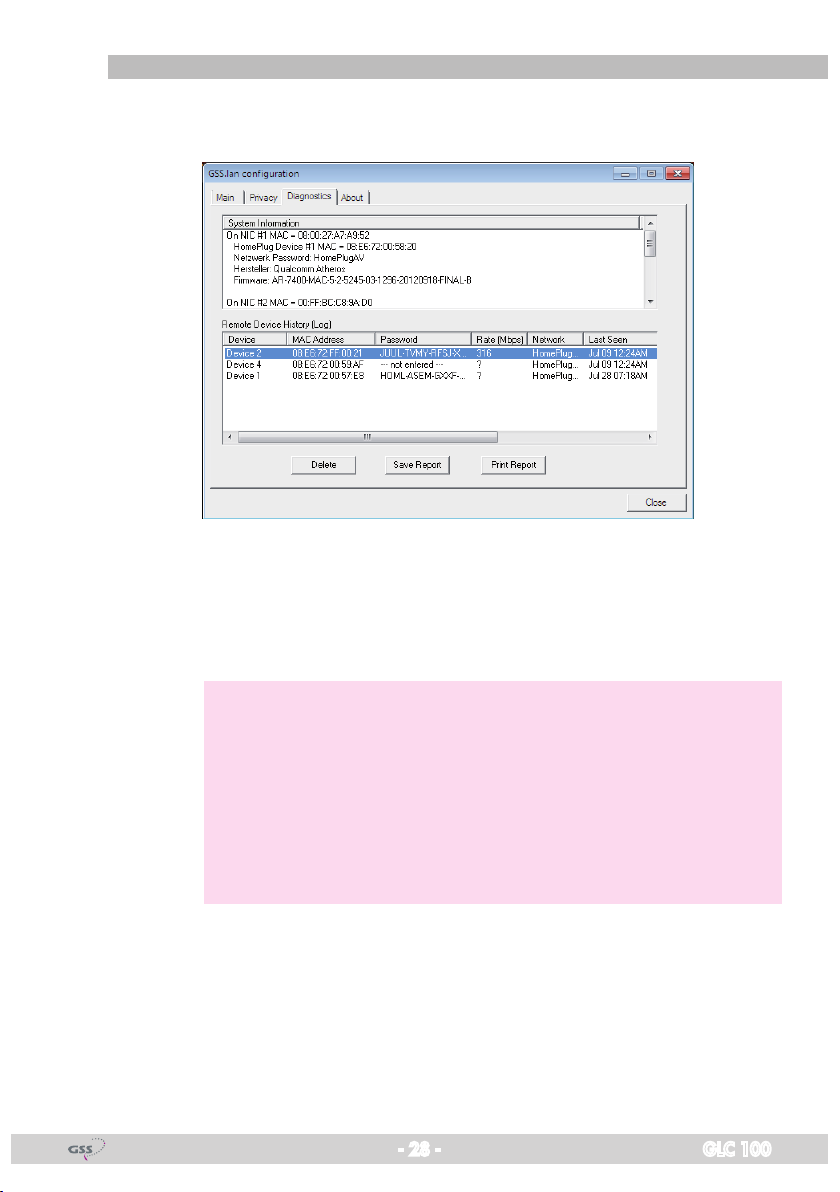
diag n ostiC s
The "Diagnostics" menu provides system information and a history of the ex-
ternal modems which where "active" over a period of time.
In the upper section specifications of software, firmware and hardware of the
EoC modem, which is connected locally to the PC, are displayed.
In the lower section a history of network-connected modem is included. Here
all the modems contained in the network are listed with some additional parameters.
—> For external modems, the following information is available:
– Device Name
– Device MAC address
– Device password
– Last known data rate of an active device
– Last known network name of the device
– The date on which the device was found on the network for the
last time
The information displayed can be stored for later use in a text file. Modems
that are no longer part of the network, can be deleted using the "Delete" button. When trying to delete a device whose password has been entered, a
dialogue screen for confirmation will appear.
- 28 - GLC 100

info
In section "Preferences" the "AutoScan" function can be switched on or off.
If AutoScan is enabled (default), the network will be scanned at certain inter-
vals and newly connected / activated modems will be displayed in the lower
section of the main menu.
In order to update the network status at deactivated "AutoScan", click on but-
ton "Scan" in the main menu (page 23).
- 29 - GLC 100

8 drill temPlate
90 mm
41 mm
- 30 - GLC 100

Declaration of CE conformity
- 31 - GLC 100

Service:
Phone: +49 (0) 911 / 703 2221 • Fax: +49 (0) 911 / 703 2326 • Email: service@gss.de
Grundig SAT Systems GmbH • Beuthener Straße 43 • D-90471 Nuremberg
Alterations reserved. Technical data E. & O.E. © GSS GmbH 04062014
 Loading...