

Page 1
STC 4-16 IPS CI
Default access data:
192.168.0.120
User: admin
Password: geheim
Assembly Instruction
Page 2

Contents
1 Safety regulations and notes ........................................................................4
2 General information ....................................................................................6
2.1 Packing contents ............................................................................6
2.2 Meaning of the symbols used ..........................................................6
2.3 Technical data ...............................................................................6
2.4 Description ...................................................................................8
Block diagram ...............................................................................8
General ........................................................................................8
Streaming .....................................................................................9
3 Assembly ..................................................................................................10
3.1 Installing the device .....................................................................10
3.2 Device overview ..........................................................................11
3.3 Potential equalisation (PE) .........................................................12
3.4 Connecting the device ..................................................................12
3.5 CI Slots ......................................................................................13
4 Configuration / Updates ............................................................................14
4.1 Initial configuration ......................................................................14
4.2 Configuration ..............................................................................17
Overview window .......................................................................17
Perform changes .........................................................................18
Number format............................................................................18
Configuration menus ....................................................................19
Input .....................................................................................19
Output ..................................................................................21
CA .......................................................................................28
System menus .............................................................................30
Logbook ................................................................................30
Notification ...........................................................................31
Network ................................................................................33
OpenVPN .............................................................................34
Security .................................................................................35
Firmware ...............................................................................36
- 2 - STC 4-16 IPS CI
Page 3

- System settings: ....................................................................36
- Firmware update: .................................................................37
- Backup: ...............................................................................38
- Manager: ............................................................................38
- Reset to factory defaults: ........................................................38
- System restart: ......................................................................38
- Ping (Network Diagnostic Tool): ..............................................39
User ......................................................................................39
5 Multiple satellite reception .........................................................................40
5.1 Reception of up to 4 satellites ........................................................40
Overview ...................................................................................40
Menu Configuration > Input ..........................................................41
Installing the SDUC 516 ...............................................................42
Potential equalisation (PE) ........................................................42
Connecting the SDUC 516 ..........................................................43
Appendix ......................................................................................................44
Panasonic VIERA TV Sets .......................................................................44
Configuration steps at the head-end station .....................................44
Upload the M3U List directly to the TV sets ................................44
Upload a link to the M3U List to the TV sets ...............................44
Configuration steps at the VIERA TV Sets ........................................44
Enable DVB-via-IP reception .....................................................45
DVB-via-IP – Update the M3U-Liste or Link ..................................45
- 3 - STC 4-16 IPS CI
Page 4
1 safety regulations and notes
• The devices meet the EU directives 2011/65/EU, 2014/30/EU and
2014/35/EU.
• This device is subject to the provisions of protection class I. Operate the
device only to mains sockets with protective conductor connection!
• If the power cord needs to be replaced, only use an OEM power cord.
• The standards EN/DIN EN 50083 resp. IEC/EN/DIN EN 60728 must be
observed, especially concerning equipotential bonding and earthing.
• Observe the relevant country-specific standards, regulations and guidelines
on the installation and operation of antenna systems.
• Before starting installation or service work disconnect the receiving system
from mains.
• Do not perform installation and service work during thunderstorms.
• Assembly, installation and servicing must be carried out by an authorised
electrician.
• For a complete disconnection from the mains, the mains plug must be pulled
out of the mains socket. Ensure that the mains plug can be pulled out without
difficulties.
• The head-end station should only be installed in a room where the permissible ambient temperature range (0 °C … +50 °C ) can be maintained, even
during fluctuations in climatic conditions.
• Make sure there is a minimum space of 10 cm on either side and 50 cm
above and below.
• To avoid too strong interacted heating of the head-end stations it is not
admissible to mount them one upon the other without using thermic precautions (e.g. permanently air recirculation, ventilation, heat deflectors etc.).
• If additional fans are to be used to circulate the air, ensure that the system
will be shut down (disconnected from mains) should any one of the fans fail.
• Install the head-end station
- in a dry, dust-free environment, in such a manner that it is protected from
moisture, fumes, splashing water and dampness
- where it is protected from direct exposure to sunlight
- on a vibration-free wall or floor construction
- not within the immediate vicinity of heat sources
• In case of the formation of condensation wait until the system is completely
dried.
• Ensure that the head-end station is adequately ventilated.
• Do not cover the ventilation openings!
• Do not install the head end in cabinets or recesses which are not ventilated.
- 4 - STC 4-16 IPS CI
Page 5

• Do not place any vessels containing liquids on the head-end station.
• Do not place anything on the head-end station which could initiate fires
(e.g. candles).
• Due to the risk of fires caused by lightning strikes, we recommend that
all mechanical parts (e.g. distributor, equipotential bonding rail, etc.) be
mounted on a non-combustible base. Wood panelling, wooden beams,
plastic covered panels and plastic panels are all examples of combustible
bases.
• Avoid short circuits!
• To ensure electromagnetic compatibility, make sure all connections are tight
and that the covers are screwed on securely.
• No liability is accepted for damage caused by faulty connections or inappropriate handling of the device.
• The firmware contains components which are licensed as Open Source
software. The components to which this relates and the respective license
terms can be called up via menu Help/Licences.
This parts of software source code can be provided at cost price on CD
upon request. The licensee is granted a non-exclusive right of use for the
Open Source Software by the respective right holders used; the conditions
stipulated by the respective valid license terms apply. The license terms of
this license only apply to the components which are not listed as Open
Source software.
In relation to the licensor the regulations on liability and warranty in these
license terms apply for the whole software. The liability and warranty regulations of the Open Source licenses only apply in relation to the respective
right holders.
• Test the firmware versions of the device and update them if necessary. The
current firmware version can be found at "www.mygss.eu".
Take action to prevent static discharge when working on the device!
Electronic devices should never be disposed of in the household rubbish. In
accordance with directive 2002/96/EC of the European Parliament and the
European Council from January 27, 2003 which addresses old electronic and
electrical devices, such devices must be disposed of at a designated collection
facility. At the end of its service life, please take your device to one of these
public collection facilities for proper disposal.
- 5 - STC 4-16 IPS CI
Page 6
2 general information
2.1 PaCk in g Co nt ents
1 STC 4-16 IPS CI 1 LAN cable
1 Brief assembly instructions 1 Mains cable
2.2 meani ng of t h e sym b o l s us e d
Important note
Danger by electrical shock
—> General note
• Performing works
2.3 te C h niCal da ta
The devices meet the following EU directives:
2011/65/EU, 2014/30/EU, 2014/35/EU
The product fulfils the guidelines and standards for CE labelling (page 46).
Unless otherwise noted all values are specified as "typical".
RF input DVB-S/S2 (ETSI 300 421)
Frequency range: ....................................................... 950 … 2150 MHz
DVB-S modes: ............................................................................... QPSK
DVB-S2 modes: ........................................ QPSK, 8PSK, 16APSK, 32APSK
Symbol rate DVB-S: ............................................ QPSK: 1 … 45 MSymb/s
Symbol rate DVB-S2:
QPSK ................................................................... 4.5 … 45 MSymb/s
8PSK .................................................................... 4.5 … 45 MSymb/s
16APSK ................................................................ 4.5 … 39 MSymb/s
32APSK ................................................................ 4.5 … 32 MSymb/s
Maximum data rate/tuner ......................................................... 83 MBit/s
Level range: ............................................................ 60 dBμV … 80 dBμV
Input impedance: ............................................................................ 75 Ω
LNC supply total: ................................................................max. 500 mA
- 6 - STC 4-16 IPS CI
Page 7

LAN interface for Streaming
Standard: ........................................................................... 1000-BASE-T
Data rate: .......................................................................... ≤ 820 MBit/s
IGMP ................................................................................................V2
Protocols: .......................................................... UDP (User Data Protocol),
RTP (Real-Time Transport Protocol)
LAN interface for configuration
Standard: ............................................................................. 100-BASE-T
Connections
SAT inputs: ............................................................................. 4 F sockets
LAN output for streaming: ................................................... 1 RJ 45 socket
LAN input for configuration: ................................................ 1 RJ 45 socket
Common Interfaces ...............................................................................6
General
Mains voltage: .................................................. 200…240V~, 50/60 Hz
Power consumption without LNC/CI ................................................. 30 W
Maximum Power consumption: ........................................................ 55 W
Admissible ambient temperature: ............................................0 … +50 °C
Dimensions (WxHxD): ............................................. 341 x 282 x 105 mm
Weight: .......................................................................................... 7 kg
- 7 - STC 4-16 IPS CI
Page 8
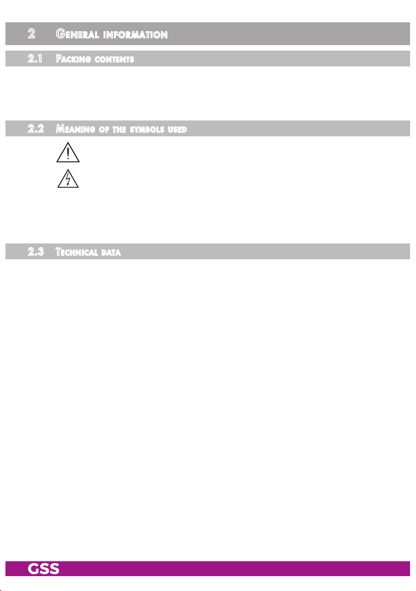
2.4 des Cr i P tion
The head-end station converts 16 transponders modulated acc. to DVB-S/
DVB-S2 standard (up to 32 APSK) into up to 128 SPTS transportstreams (maximum over all output data rate 820 MBit/s). In conjunction with specially programmed multiswitches up to four satellites can be received (multiple satellite
reception – option dCSS/Unicable II page 40).
bloCk d iag r am
Option dCSS/Unicable II
4 x SDUC 516
ASTRA 19,2
f1
f2
f3
f4
ASTRA 23,5
f1
f2
f3
f4
Hotbird
f1
f2
f3
f4
Türksat
f1
f2
f3
f4
SAT IN 1
SAT IN 2
SAT IN 3
SAT IN 4
Tuner "1"
Tuner "6"
Tuner "7"
Tuner "16"
6
x
CI
STC 4-16 IPS CI
SPTS
TPS –>
SPTS
Streams
LAN DATA
ge neral
The station is equipped with four SAT IF inputs, one Gbit LAN data output and
one 100Mbit configuration LAN input. It is preset to receive the most popular
ASTRA transponders. Different programming is possible at any time.
Each of the 16 tuners can be assigned to any SAT input.
Using adequate CA modules scrambled channels can be descrambled via tun-
ers "1"…"6".
The configuration of the station is to be done via an HTML user interface via a
PC and a standard HTML browser connected to the Control input.
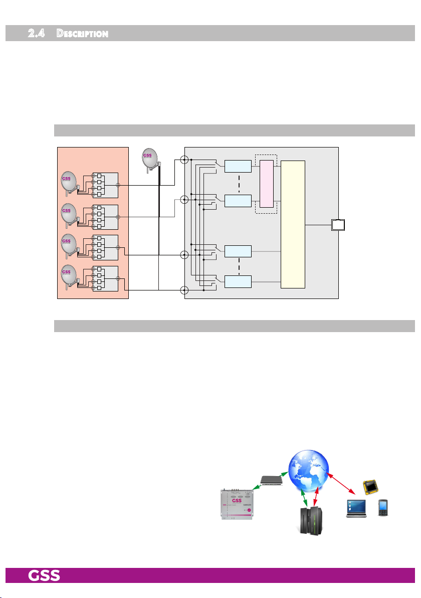
After the initial setup, you have
worldwide access to the station via
an OpenVPN connection – by PC,
tablet or smart phone with Internet access. Therefor observe menu
OpenVPN on page 34.
- 8 - STC 4-16 IPS CI
GSS
OpenVPN
Server
Page 9

—> When using mobile terminals – dependent on your mobile contract – ad-
ditional connection costs / data transfer costs may also be incurred here.
16 LEDs provide an indication of the SAT IF input signal quality based on their
colour.
str e a m i n g
Live Streaming/Multicast Streaming requires specially designed and config-
ured networks.
• Make sure the LAN network is adapted and configured for streaming!
Therefore note menu Help > Multicast Setup or www.mygss.eu > Service >
Service Informations > IPTV network setup..
- 9 - STC 4-16 IPS CI
Page 10
3 assembly
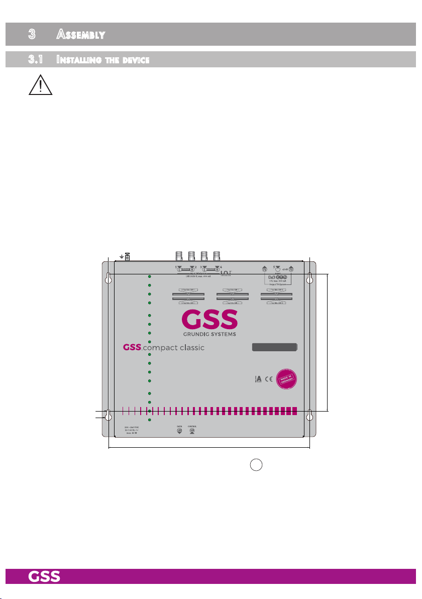
3.1 inst alli ng the d e v i Ce
– The device must not be operated lying down, since the function of the heat
sink will be severely restricted. Only with vertically arranged cooling fins
sufficient cooling is ensured.
– The device should only be installed in a room where the permissible ambi-
ent temperature range (0 °C … +50 °C ) can be maintained, even during
fluctuations in climatic conditions.
– Mount the device on a non-combustible base.
– Use mounting material suitable for the wall properties.
– Position the device with a minimum distance on the left and right side of
10 cm, below and above 50 cm.
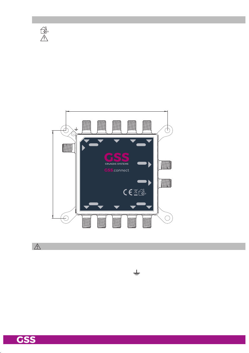
• Attach four mounting screws at the installation site. The drilling distances
are shown in the drawing below.
# #
Ø6 mm
Ø12 mm
STC 4-16 IPS CI
318 mm
222 mm
• Hang the unit with the mounting supports 13 on the 4 screws.
• Tighten the screws.
- 10 - STC 4-16 IPS CI
Page 11
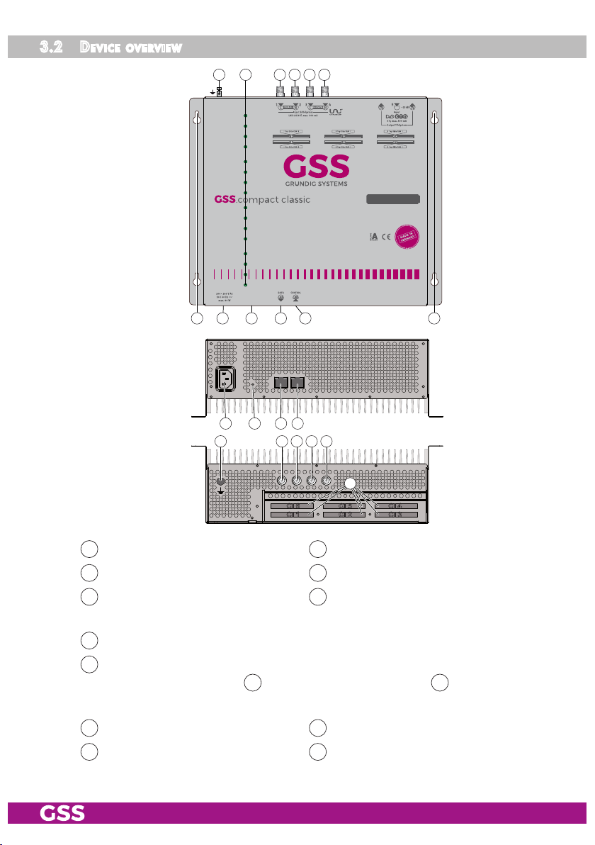
3.2 deviC e ov erview
1 2 3 4 5 6
1
2
3
4
5
6
7
8
9
10
11
12
13
14
15
16
913 1310 11 12
STC 4-16 IPS CI
9 10 11 12
65431
14
CI 6
CI 1
CI 5
CI 2
CI 4
CI 3
Connector potential equalisation 2 Reception LEDs of tuners 1…16
1
SAT IF input vertical low*
3
SAT IF input horizontal low*
5
SAT IF input vertical high*
4
SAT IF input horizontal high*
6
* Factory defaults for ASTRA reception, can be changed individually.
IEC connector C14; connector for mains cable
9
Reset IP address and password
10
to:
192.168.0.120 for 12 and 192.168.10.120 for 11;
(hold depressed for more than 5 seconds)
Host name gss;
Password geheim
* Use at least CAT6 LAN cables (EMC)!
- 11 - STC 4-16 IPS CI
LAN socket** streaming output
11
Mounting support
13
LAN socket** for configuration
12
CI slots
14
Page 12
3.3 Po t e nti al eq uali sat i o n (Pe)
Equalise the potential (PE) in accordance with IEC/EN/DIN EN 60728.
•
Connect the PE connection terminal 1 to a PE rail (supplied by customer)
using the PE wire (Cu 4 mm2 - 9 mm2).
3. 4 Con ne Cting the d e v i C e
• Connect the SAT IF inputs…
vertical low*; 4 vertical high*
3
horizontal low*; 6 horizontal high*
5
… to the corresponding outputs of an LNB.
*Factory defaults for the preprogrammed ASTRA reception, can be changed individually.
• Make sure that all inputs have the same level!
—> For multiple satellite reception observe the dCSS/Unicable II mode
from page 40 on.
• Connect the attached mains cable to the IEC connector C14 9.
• Connect the mains cable to a mains socket with protective conductor connection. Thereby note the voltage specified on the device.
—> This device has no power switch and starts immediately after con-
necting the operating voltage.
For a complete disconnection from the mains, the mains plug must
be pulled out of the mains socket. Ensure that the mains plug can be
pulled out without difficulties.
• Configure the device (page 14).
• Make sure the LAN network is adapted and configured for streaming!
Therefore note menu Help > Multicast Setup or www.mygss.eu > Service >
Service Informations > IPTV network setup.
• If the configuration is finished connect the streaming output 11 to the stream-
ing network.
- 12 - STC 4-16 IPS CI
Page 13
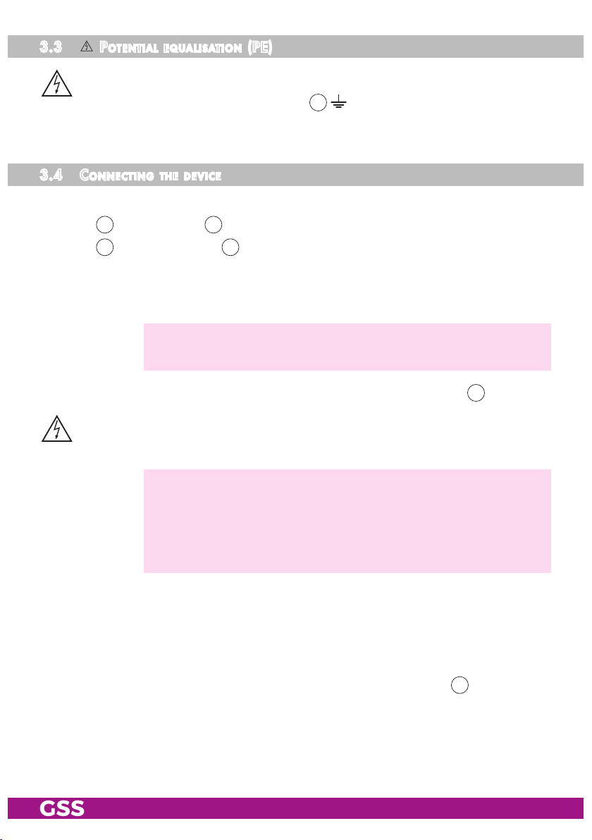
3.5 Ci sl ots
The CI slots are located under the CI cover on top of the case.
• Unscrew 4 screws 15 and remove the cover.
15
—> Note for the selection of slots:
Slots 1…6 are assigned to the tuners 1…6. If a CA module is not
sufficient to descramble all channels of a transponder, alternatively
the modules 6…4 can be assigned to the tuners 1…3 additional:
– Module 1 + 6 for tuner 1,
– Module 2 + 5 for Tuner 2 and
– Module 3 + 4 for Tuner 3.
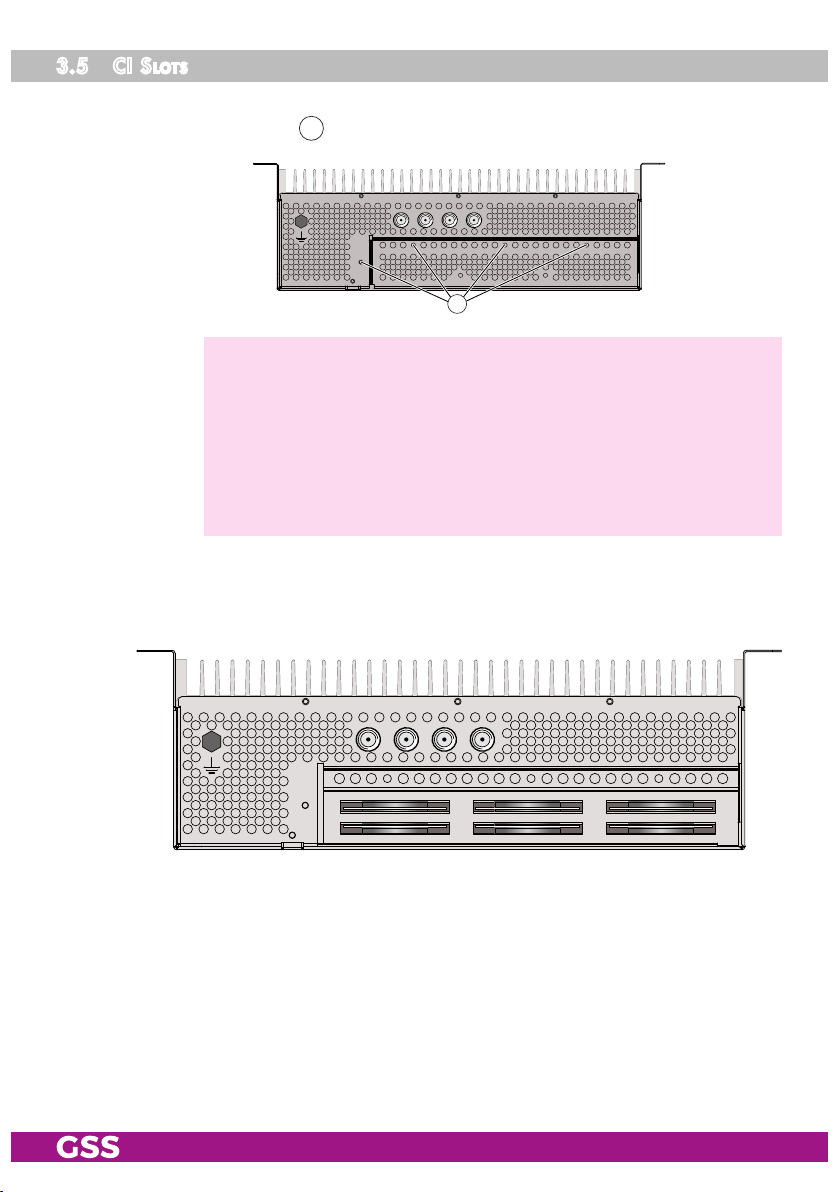
• Insert the CA modules …
– for slots 1 … 3 with the (thicker) top side towards housing-front, …
– for slots 4 … 6 with the (thicker) top side towards rear panel (heat sink).
6
1
5
2
4
3
• Final mount again the CI cover (EMC).
- 13 - STC 4-16 IPS CI
Page 14
4 Configuration / uPdates
The configuration of the station is to be done via an HTML user interface via a
PC and a standard HTML browser.
4.1 init ia l C o n f i gur at i o n
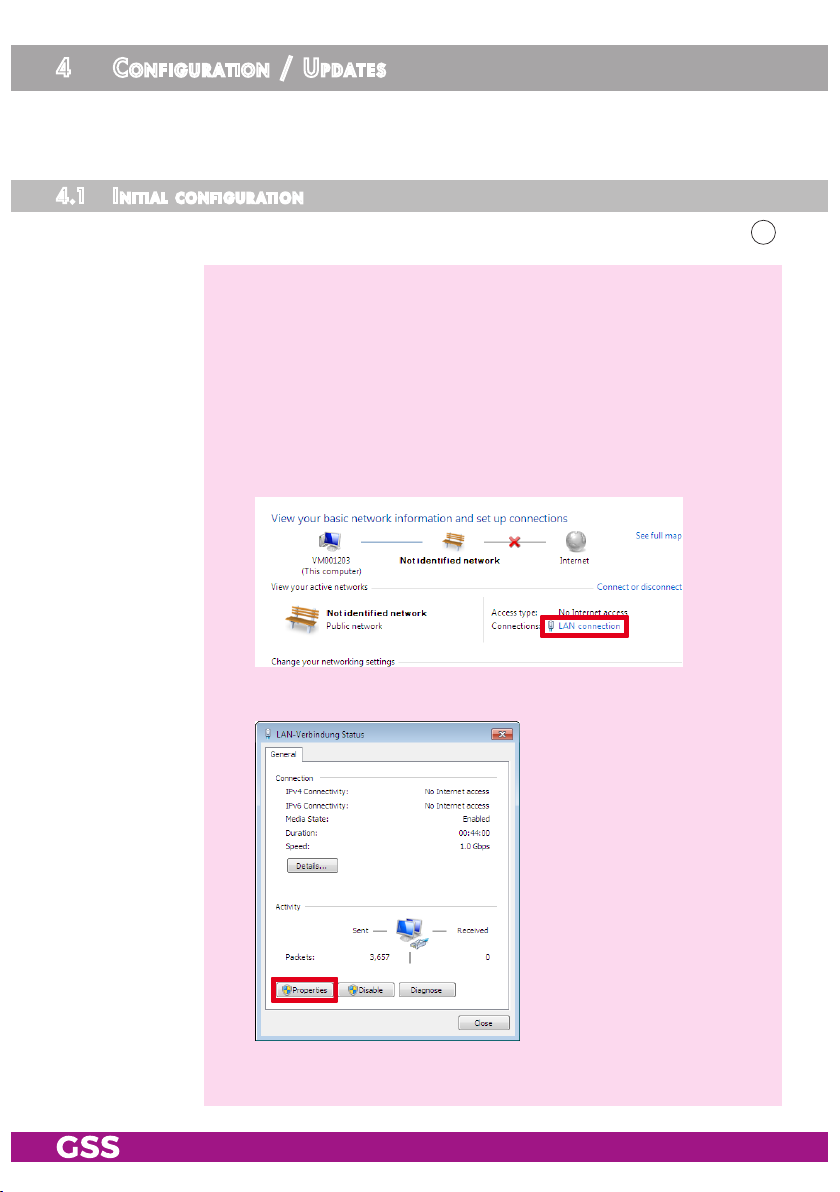
• Connect a PC via a CAT6 LAN cable directly to the configuration input 12.
—> The PC and the head-end station must be within the same network
(same IP address range). Cookies must be accepted and JavaScript
must be active.
Use current browser versions.
—> Example for IP address setting with Windows 7 operating system:
• For the initial setup open the properties for TCP/IPv4 of the PC:
> Control Panel
> Network and Sharing Center
> LAN connection
> Properties
- 14 - STC 4-16 IPS CI
Page 15

> Internet Protocol Version 4 (TCP/IPv4)
> Properties
• Activate point "Use the following IP address".
• Enter e.g. 192.168.0.2 for the IP address.
• Enter for the Subnet mask 255.255.255.0.
• Confirm the setting with "OK".
- 15 - STC 4-16 IPS CI
Page 16

• Start the browser, enter the IP address of the device (factory default is
192.168.0.120) and start the establishment of the connection.
• Enter user admin and your Password and click on button "Login".
The default password is geheim.
—> We recommend that you replace the default password to a pass-
word of your choice in order to prevent unauthorized access to the
head-end station (menu System > Security)!
—> For further logins observe the menus System > Network and System
> OpenVPN!
—> The Overview window is displayed.
First, an "empty" table is displayed (as with all menus). While the
data is read from the device ...
… is displayed.
—> Changes in the menus are only transmitted to the head-end station
when you click the button!
- 16 - STC 4-16 IPS CI
Page 17

4.2 Con fi gur at i o n
ov erv ie w wi nd ow
50
54
58
55
57
51
52
53
56
59
61
50
Logbook (page 30); Notification (page 31); Network (page 33);
OpenVPN (page 34); Security (page 35); Firmware (page 36);
User (page 39)
Via the selection System you have access to the System settings menus:
51
In all menus you will return to the Overview via the button Overview.
52
Via the selection Configuration you have access to the Configuration set-
ting menus: Input (page 19); Output (page 21); CA (page 28).
53
Herein the installed firmware version is displayed.
54
- 17 - STC 4-16 IPS CI
This location text can be modified arbitrary in menu System/User (page 39).
—> If you remote control head-end stations at different locations, herein
you can enter the location and a local contact person.
55
Select menu language (English/German)
56
Herein date and time of the last login is displayed.
57
Via button Logout you can leave the graphical user interface.
Page 18

58
Via the Help menu you can call up the assembly instructions (PDF), hints
about the configuration of a multicast network (PDF) as well as a ZIP file
containing a list and all licences of the used OpenSource software.
59
Overview of the transponders set, with input frequency, C/N value, services at the output with multicast addresses. Via the background colour
of column Line you are informed about the quality of the input signals
( good/ bad/ no signal).
—> If in menu Configuration/Input (page 19) transponder names are
—> The maximum displayed C/N value is 15.0dB at DVB-S resp.
61
Via button Download a configuration protocol can be stored as text file
respectively opened using a text editor.
—> From this protocol file e.g. a list of the programmed stations can be
Perfo r m C hange s
NOT assigned, the name of the first station of each transponder is
displayed.
20.0dB at DVB-S2. This means the actual value is ≥15/20dB.
prepared using e.g. a text editor.
Before leaving a menu, changes must be transmitted to the head-end station.
• Therefore click on button .
After that is displayed for a short time in the upper right corner.
number format
For entering/indication of the different IDs the number format can be set to
hexadecimal or decimal in menu System > Firmware.
- 18 - STC 4-16 IPS CI
Page 19

Confi gu r at io n men us
in Put
102
100
104
110
105 106 107 108 109
103
101
102
103
101
—> Via the background colour of column Line you are informed about
the quality of the input signals ( good/ bad/ no signal).
100
In column f
, enter the LNB Oscillator frequencies for the 4 inputs – de-
LNB
pendent on the LNB used.
—> In dCSS/Unicable II operating this column is omitted.
You need Quattro LNBs with 9.75 / 10.6 GHz oscillator frequency.
For multiple satellite reception observe the dCSS/Unicable II mode
from page 40 on.
101
In column Name, enter a personal input name.
—> If dCSS/Unicable II is activated you can assign the four levels of a
satellite to each input.
- 19 - STC 4-16 IPS CI
Page 20

102
With button LNB Power switch on or off the LNB power supply (max.
500 mA). If necessary switch the 14V/18V power supply to 14V "only"
using button 14V fixed.
103
dCSS/Unicable II Mode (page 40) on/off.
104
In column Name, you can enter a personal transponder name
—> If you delete a transponder name, the name of the first station of
this transponder is entered. If the transponder will be changed, the
transponder name will NOT be changed automatically!
105
In column Input, select the desired input for each tuner.
106
In column f (MHz), enter the desired input frequency for each tuner.
107
In column SR (kS/s), enter the related input symbol rate for each tuner.
108
In column f
—> The frequency offset should not exceed ± 1.5 MHz!
IF necessary correct the LNB oscillator frequency (if all transpond-
, the current frequency offset is displayed.
offset
ers of one input are affected) resp. the input frequency (if only one
transponder is affected) accordingly.
109
In this column, the C/N is displayed with reserve.
—> The maximum displayed C/N value is 15.0dB at DVB-S resp.
20.0dB at DVB-S2. This means the actual value is ≥15/20dB.
110
Before leaving the menu, changes must be transferred to the head-end
station!
• Therefore click on button .
—>
After that is displayed for a short time in the upper right corner.
- 20 - STC 4-16 IPS CI
Page 21

ou tPu t
155154 150 151 152 157
161
162
163
166
158 159
160156
153
164
165
150
Herein select the protocol UDP or RTP for all output streams.
—> For Panasonic TVs RTP must be set.
151
Herein you can switch off the transmission of the EPG data (Electronic
Programme Guide), in order to reduce data rate for more services.
—> 1.5Mbit/s for EPG per service are quite possible!
EIT = Event Information Table
- 21 - STC 4-16 IPS CI
Page 22

152
Herein the over all output data rate of all active streams (
155
is "ON") is
displayed (∑ column "DR").
153
Via buttons "Edit" you can change the settings for the columns
row by row (stream by stream).
—> Button OK confirms the settings.
Button Cancel aborts the settings.
Button Delete deletes Service, Ch.-No.
and SAP Group.
—> An arrow in front of the service indicates that this service is already
available at the output.
154
The value shows the current output data rates of the different streams, if
155
is set to "ON".
155
Column Output indicates whether a stream is switched on or off.
156
Indication of current services which are set as SPTS streams.
—> The input line (e.g., L01 = line 1/tuner 1) and service ID/type are
displayed in the bracket.
157
Indication of the Multicast IP Addresses
Multicast IP addresses are assigned to the streams (
switches recognize the addresses automatically and, if configured accordingly, route the streams only on request to end devices. This greatly
reduces network traffic.
155…160
153
). IGMP-capable
—> IP addresses in the range 224.0.0.0-239.255.255.255 are mul-
ticast addresses, but many addresses in this range are reserved
(www.iana.org/assignments/multicast-addresses).
—> Use the 239.x.y.z range! It is suitable for streaming TV content and
must also be used for Panasonic Viera TVs.
For x use only the range of 1…127.
The range 0 ... 255 is available for y and z.
—> You will find descriptions to important terms for configuring a
streaming network in menu Help > Multicast Setup.
- 22 - STC 4-16 IPS CI
Page 23

158
Indication of output port setting
159
Channel Number: Specifies a station assignment for clients that are pro-
grammed via the M3U or xml list (
162, 164
).
160
SAP Group (Groups/Genres for
161
Herein you can perform a quick setup for columns
162
)
155…160
as well as add
external services.
Quick-Setup:
—>
By entering "Idx - from - to" you can select the lines for which you
want to make changes. If you do not enter a value, programming
is carried out from line 1 to line 128, but only for those columns for
which you have entered changes.
—>
If you set a check mark at "Output change", the corresponding
outputs are switched on or off depending on selection / .
You can delete the contents of the columns "Service", "Prog.-No."
and "SAP group" when selecting "reset" for each column.
In the "Start IP" field, you can enter the output IP address for row 1.
This address is then increased by 1 in each additional row.
In the field "
Prog.-No.
" you can enter the station number for row 1.
This number is then increased by 1 in each additional row.
Entries in the fields "Port" and "SAP Group" are transferred to all
fields in the columns.
• Click on "accept", check the information and confirm with "OK".
Example:
- 23 - STC 4-16 IPS CI
Page 24

Add external services:
Added services are displayed in the overview starting from row 129 and
entered in the various lists (SAP, M3U, xml
162, 164
)
.
162
Herein switch on/off the transmission of the Session Announcement Protocol.
—>
If you want to use SAP, activate it at all parallel stations.
—> Clients who are able to process SAP, receive information on which
services are transferred with which multicast IP address as well as
about the groups entered in the "SAP group" column.
"Announcement delay" indicates the interval at which the data is
sent. Change the value only if the clients have problems with receiv-
ing the SAP data.
163
If this switch is set to "ON", the services of other stations which are oper-
ated in parallel are added to the M3U/xml lists (
tion list (
165
).
164
) and the documenta-
—> The query is made via the configuration interfaces. The IP addresses
of the configuration interfaces of the stations must be in the same IP
address range, e. g. 192.168.0.x.
—> In the case of parallel stations, activate this switch only at that sta-
tion at which you generate the lists.
—> Changes at the parallel stations are not imported for
164
until
is executed.
- 24 - STC 4-16 IPS CI
Page 25

164
Clients:
Here you can download service allocation tables for clients of different
manufacturers or a path for linking the clients to the head-end station.
—> The corresponding list is only generated if the protocol
for the clients is set.
—> Please also note
163
!
150
required
Panasonic VIERA IPTV sets:
Download the configuration file "satip_multicast.txt" for the configuration
or streaming interface. This file contains the path to the service list (M3U
list) that you can load into the clients. In this way, future changes to the
service list are automatically adopted by the client.
—> The clients require a permanent connection to the head station.
Select the Configuration file for the interface with the corresponding
IP range.
—> You will find hints about the TVs setup in the Appendix (page 44).
Alternatively, download the service list (satip.m3u) to import it into the
clients.
—> You will find hints about the TVs setup in the Appendix (page 44).
- 25 - STC 4-16 IPS CI
Page 26

VESTEL IPTV sets:
Here you can download the service list (channelTable.xml) for Vestel Ho-
tel TVs.
Alternatively, note the path (Server URL) to the service list for the configu-
ration or streaming interface. You can enter this path in the clients. In this
way, future changes to the service list are automatically adopted by the
client.
—> The clients require a permanent connection to the head-end station.
Select the path for the interface with the corresponding IP range.
—> Clients only update the list if the "Channel List Version" has in-
creased. If changes are made, the version is changed automati-
cally. If you want to integrate the head-end station into an existing
TV network, you can adjust the value to the TV sets in the Channel-
ListVersion input field.
BEWATEC IPTV-Geräte:
Here you can download the service list (channels_bewatec.xml) for Be-
watec IPTVs.
Alternatively, note the path (Server URL) to the service list for the configuration or streaming interface. You can enter this path in the clients. In this way,
future changes to the service list are automatically adopted by the client.
—> The clients require a permanent connection to the head station. Se-
lect the path for the interface with the corresponding IP range.
- 26 - STC 4-16 IPS CI
Page 27
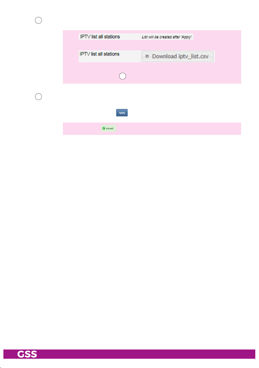
165
Here you can download a Station list in form of "*.csv" file.
—>
First you must execute "Apply" to create the list.
—> It also includes services which are switched off.
—> Please also note
166
Before leaving the menu, changes must be transferred to the head-end
73
station!
• Therefore click on button .
—>
After that is displayed for a short time in the upper right corner.
!
- 27 - STC 4-16 IPS CI
Page 28

Ca
In menu CA you can make
changes in assignment of the
CA modules (CAMs) as well as
define which services should be
descrambled. In addition you
get access to the CAM status
indications as well as the CAM
menus.
200
By default, CAM slots
1…6 are assigned to lines
1…6. By menu point CA
Mode you can change
the assignment of the CA
slots. If one CA Module is
not enough to completely
descramble a transponder,
here in addition you can
assign the CA modules 6-4
to lines 1-3.
CI 1…6 —>
CI 1+6 —>
CI 2…5 —>
CI 1+6 —>
CI 2+5 —>
CI 3…4 —>
lines
line
lines
line
line
lines
1…6
1;
2…5
1;
2;
3…4
200
201
202
204
205
206
207
209
203
208
1–>1; 2–>2; 3–>3; 4–>4; 5–>5; 6–>6
Line 6
Line 1
1–>1+6; 2–>2; 3–>3; 4–>4; 5–>5
Line 1
+
Line 1
1–>1+6; 2–>2+5; 3–>3; 4–>4
Line 1 Line 2
+ +
Line 1
Line 5
6
1
Line 2
Line 5
6
1
Line 2
6
1
Line 2
Line 4
5
2
Line 3
Line 4
5
2
Line 3
Line 4
5
2
Line 3
4
3
4
3
4
3
CI 1+6 —>
CI 2+5 —>
CI 3+4 —>
line
line
line
1;
2;
3
1–>1+6; 2–>2+5; 3–>3+4
Line 1 Line 2 Line 3
6
+ + +
1
Line 1
5
2
Line 2 Line 3
- 28 - STC 4-16 IPS CI
4
3
Page 29

201
The CA State indicators inform by their background colour about the
CAM conditions:
grey - CAM slot empty
blue - CAM detected
green - CAM is working
red - CAM error
202
Here you can activate/deactivate the CA Check for
Video PIDs or all PIDs.
—> If particular PIDs are not descrambled the CA module is reset.
203
Via button Open CA Menu you get access to the individual menus of the
CAMs (content is dependent on the CAM).
Via pull down menu CA Slot select the corresponding CAM.
Use the 10-key keyboard to control the menus by mouse click.
End the CAM settings by Close CA Menu button.
204
Herein you can select whether only one line is displayed or all lines are
displayed.
205
- 29 - STC 4-16 IPS CI
Indication of TS-/ON-ID.
—> For entering/indication of the different IDs the number format can
be set to hexadecimal or decimal in menu System > Firmware.
Page 30

206
In column CA, select whether, and if so, with which CA module services
are to be descrambled.
do not descramble / descramble
207
In column Pass Service the stations (services) are displayed.
—> indicates scrambling.
208
Via button Reset CA filter, setting for column CA
defaults ( do not descramble).
209
Before leaving the menu, changes must be transferred to the head-end
station!
• Therefore click on button .
—>
After that is displayed for a short time in the upper right corner.
sy s t em m e n u s
lo gbo ok
In the logbook different alerts or
events are displayed. This helps
at a possible troubleshooting.
300
Herein you can select
whether only one line is
displayed or all lines are
displayed.
301
Via this button you can
clear the logbook.
206
are reset to factory
300 301 302
302
Via this button you can refresh the indication.
—> Please also note the items
310
and
311
in the Notification menu
(page 31).
—> The logbook is included in the protocol file (page 17)!
- 30 - STC 4-16 IPS CI
Page 31

noti fi C at i o n
In this menu you use the reaction time to set when entries for input signal or
data overflow errors are entered in the logbook (page 30).
Enter the access data for the outgoing mail server of your e-mail account here
if you want to be informed about error entries in the logbook by e-mail. The
e-mail is then sent via the outgoing mail server of your e-mail account to the
inbox of the recipient.
—> Therefor the configuration interface must have access to the Internet.
310
312
314
316
317
319
321
310
Enter the duration in seconds that an input signal or data overflow error
must occur for an entry to be made in the logbook.
311
Enter here the duration in seconds which must be a signal "OK" again
for an entry to be made in the logbook.
312
Herein enter the e-mail address to transmit the e-mail.
313
Herein enter the password for the outgoing mail server of your e-mail account.
314
Herein enter the outgoing mail server of your e-mail account.
315
Herein enter the port of the outgoing mail server of your e-mail account.
316
Herein select the e-mail encryption which is supported from your e-mail
provider:
– "TLS/STARTTLS" (usually Port 587) or
– "SSL" (usually Port 465)
311
313
315
318
- 31 - STC 4-16 IPS CI
Page 32

317
Herein enter the mail address of the recipient.
318
Via button send alarm mail you can send a test mail.
—> Before you can send a test mail, changes must be transferred to the
head-end station! Therefore click on button .
—> Example:
—> If OpenVPN is activated, the Personal Link is also displayed here so
that you can connect to the station immediately.
—> In the e-mail, the contact details, which are stored in menu System >
User are displayed to identify the head-end station.
319
Enter here how long new e-mails will not be sent.
—> In order to prevent you (e. g. in case of changing reception condi-
tions) from being flooded with e-mails, the function is blocked for
this time after sending an e-mail. The lock can be removed by deleting the logbook.
321
Before leaving the menu, changes must be transferred to the head-end
station!
• Therefore click on button .
—>
After that is displayed for a short time in the upper right corner.
- 32 - STC 4-16 IPS CI
Page 33

net wor k
Herein you customize the IP Addresses,
Gateways and Subnet Masks for the
configuration interface and the streaming interface to the local network.
The configuration interface and the
streaming interface must be assigned
to different IP address ranges (fac-
tory setting 192.168.0.120 and
192.168.10.120)!
Enter fixed IP addresses which are not
yet assigned and are out of the DHCP
range of the router.
You can use the Hostname to call up the
user interface without entering the IP address. To do this, enter the host name
followed by ".local" in the browser (e.g. gss.local). If you operate several head
stations in the network, you must enter different names here.
—> Write down the IP addresses and the Host name! Further access to
the device is only possible via the IP address of the configuration
interface or the host name.
—> If you have forgotten your IP addresses, you can reset the
network settings and the password by the reset button (0 page 11)!
—> For remote access it is important to setup a gateway with Internet
access.
—> The MAC address is only displayed for information and can not be
changed.
—> Before leaving the menu, changes must be transferred to the head-
end station! Therefore click on button .
—>
After that is displayed for a short time in the upper right corner.
—> Note about IPTVs: If you are changing an IP address and IPTVs are
"linked" on the old IP address for the M3U list of the head-end station, you must import the changed path in the TV sets.
- 33 - STC 4-16 IPS CI
Page 34

oPenvPn
Via our VPN server you can get worldwide access to the head-end station by
an OpenVPN connection. Since the connection is made through our server,
you do not need a fixed external IP address or a dynamic DNS access.
—> In order that the OpenVPN connection works the following require-
ments must be fulfilled:
– Your PC must have access to the Internet.
– The configuration interface must have access to the Internet (already
at the system start).
– The outgoing TCP Port 1194 must be opened (e.g. at the router).
• Open menu System > OpenVPN.
• Copy the "Personal Link" http://… into the address line of your browser
and store it as favourite.
•
As there is no Internet connection at the system start for the initial configuration,
you need to reboot the device after configuration (System> Firmware> Restart).
—> If there is no Internet connection at the system start, the OpenVPN
service is deactivated temporarily.
—> The Private Link is also included in the protocol file (page 17)!
—> Via the ON/OFF button you can deactivate the OpenVPN service.
—> Before leaving the menu, changes must be transferred to the head-
end station! Therefore click on button .
—>
After that is displayed for a short time in the upper right corner.
- 34 - STC 4-16 IPS CI
Page 35

seCur it y
Herein replace the default password geheim by a password of your choice.
—> We strongly recommend that you change the default password to
prevent unauthorized access to the station.
• For authorisation enter the "old" password and after that the "new" password twice.
—> Before leaving the menu, changes must be transferred to the head-
end station! Therefore click on button .
—>
After that is displayed for a short time in the upper right corner.
—> If you have forgotten your password, you can reset the network set-
tings and the password by the reset button (0 page 11)!
- 35 - STC 4-16 IPS CI
Page 36

firmware
Herein select the time zone, automatic daylight saving time and the number
format (hexadecimal/decimal). In addition a firmware update, backup, factory reset as well as a system restart (warm start) can be done. The manager
allows you to store different configurations in the head station.
- sy ste m set ti n gs:
332
Herein select the time zone setting dependent on the location of the head-
end station. The head-end station receives the Coordinated Universal
Time – UTC from the satellite. Enter the corresponding UTC offset.
332
335
336
338
342
343
333
334
337
339
340
341
344
—> Herein the "standard" or "wintertime" must be set.
—> In order e.g. to adjust the Central European Time – CET, the offset
must be set to +1 hour.
333
Herein you can switch off or on the automatic daylight savings time (DST).
334
Herein you can select the number format for entering/indication the dif-
ferent transport stream IDs (hexadecimal/decimal).
- 36 - STC 4-16 IPS CI
Page 37

335
Before leaving the menu, changes must be transferred to the head-end
station!
• Therefore click on button .
—>
After that is displayed for a short time in the upper right corner.
- fi r m wa re uPd at e:
336
Herein the firmware version of the head-end station is displayed.
• Start the firmware update via button Load firmware update from PC.
• Select the new firmware file (*.tar) in the appearing pop-up menu.
—> Therefor the firmware must be previously stored on your PC. The
current firmware version can be found at "www.mygss.eu".
Unzip the *.zip file *.tar update file + added notes
—> A firmware update may take a long time to complete.
—> Aborting the firmware update or interrupting the power supply dur-
ing the update might in worst case result in a defect of the device!
—> During the update this warning is
displayed.
After a few minutes the LEDs be-
come off, shortly after that the LED
for line 1 flashes (update is being installed).
—> After a successful update, the following message is displayed:
The head-end station then restarts.
- 37 - STC 4-16 IPS CI
Page 38

- ba C kuP:
337
Via button Save settings to PC you can download the settings from the
head-end station as "*.tar" file for backup.
—> The file name must begin with backup_ so that a restore
(e.g. backup_"device"_"date".tar).
—> Settings including password but without network settings.
338
Via button Load settings from PC you can restore the settings from a prior
downloaded backup.
- mana g e r:
In the Manager, you can save configurations in the head station.
339
Enter a name and save the configuration with the Save actual config but-
ton.
Load a configuration stored in the manager:
340
In the "Saved configurations:" field, select a saved configuration and load
it with the Load config button.
Delete a configuration stored in the manager:
341
In the "Saved configurations:" field, select a saved configuration and delete it with the Delete config button.
- res e t to faC t o ry d e fa u lt s:
342
Reset the head-end station to factory defaults via button reset to factory
defaults.
338
works
—> All settings but NOT Password and IP address!
—> If you have forgotten your password or IP address, you can reset
the network settings and the password by the reset button (hold
depressed for more than 5 seconds; 0 page 11)!
- sy ste m res tart :
343
- 38 - STC 4-16 IPS CI
Via button Reboot you can restart the head-end station (warm start).
Page 39
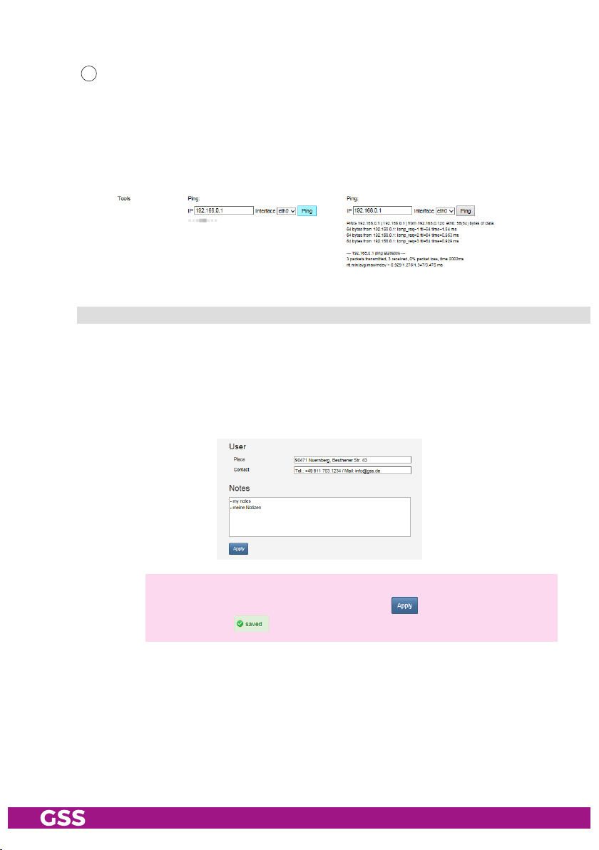
- Pi ng (n e tw ork d i agnos t i C to o l):
344
You can use the Ping button to check whether a device is accessible
on the network (also in the network to which you are connected via
OpenVPN).
• Select the interface via which the ping is to be sent.
(configuration interface = eth0; streaming interface = eth1)
• Enter the IP address you want to "ping" and click the Ping button.
user
In section User you can adjust the location-based data that is displayed in the
header of the menus accordingly. If you remotely manage multiple head-end
stations, you know at any time, at which station you just work.
In the Notes field you can enter any text that will be displayed in the overview
as a reference.
—> Before leaving the menu, changes must be transferred to the head-
end station! Therefore click on button .
—>
After that is displayed for a short time in the upper right corner.
- 39 - STC 4-16 IPS CI
Page 40

5 multiPle satellite reCePtion
5.1 reC eP t i on o f uP t o 4 s atel lites
Using four SDUC 516 transponders from up to 4 satellites (Quattro LNBs) can
be received. Therefore dCSS/Unicable II mode must be activated at the station. In this mode all inputs are working in dCSS/Unicable II mode and can
only be operated with upstream SDUC 516. Unused inputs must be completed
with DC-decoupled terminating resistors (FTD75).
The multiswitch is specially programmed for this application.
ov erv ie w
LOW HIGH
TV H V H
12V DC
LNB INPUTS
OUT 1
16 UB
SDUC 516
OUT 2
2 x 16 USER BANDS
16 UB
GSS Grundig Systems GmbH
90471 Nuernberg - Germany
LNB OUTPUTS
LOW HIGH
TV H V H
LOW HIGH
TV H V H
12V DC
LNB INPUTS
OUT 1
16 UB
SDUC 516
OUT 2
2 x 16 USER BANDS
16 UB
GSS Grundig Systems GmbH
90471 Nuernberg - Germany
LNB OUTPUTS
LOW HIGH
Potenzialausgleichsschiene
Potential equalisation rail
TV H V H
LOW HIGH
TV H V H
12V DC
LNB INPUTS
SDUC 516
2 x 16 USER BANDS
GSS Grundig Systems GmbH
90471 Nuernberg - Germany
LNB OUTPUTS
LOW HIGH
TV H V H
LOW HIGH
TV H V H
12V DC
LNB INPUTS
SDUC 516
2 x 16 USER BANDS
GSS Grundig Systems GmbH
90471 Nuernberg - Germany
LNB OUTPUTS
LOW HIGH
TV H V H
OUT 1
16 UB
OUT 2
16 UB
OUT 1
16 UB
OUT 2
16 UB
STC 4-16 IPS CI
- 40 - STC 4-16 IPS CI
Page 41

me n u C o n f i gur at i o n > i n P u t
In order that a head station with upstream SDUCs 516 works, the "dCSS/
Unicable II" switch in the input settings must be set to "ON". As a result the
preprogrammed frequencies of the SDUCs are set at the inputs of the head
station. For dCSS/Unicable II operation you need Quattro LNBs with 9.75 /
10.6 GHz oscillator frequency.
102
103
101
101
- 41 - STC 4-16 IPS CI
Personal input name
102
LNB supply on/off
103
dCSS/Unicable II Mode
Page 42
insta l ling t h e sd uC 516
– The device may only be installed in buildings.
– The device should only be installed in a room where the permissible
ambient temperature range (-20 °C … +70 °C; PSU max. 50 °C) can be
maintained, even during fluctuations in climatic conditions.
– Mount the device on a non-combustible base.
– Use mounting material suitable for the wall properties.
• If necessary attach four mounting holes at the installation site. The drilling
distances are shown in the drawing below.
• Fasten the unit.
95mm
86mm
LOW HIGH
12V DC
GSS Grundig Systems GmbH
90471 Nuernberg - Germany
LOW HIGH
TV H V H
LNB INPUTS
SDUC 516
2 x 16 USER BANDS
LNB OUTPUTS
TV H V H
OUT 1
16 UB
OUT 2
16 UB
Pot e n tial equa l i sat i o n ( Pe)
Make a potential equalisation (PE) according to IEC/EN/DIN EN 50083 resp.
IEC/EN/DIN EN 60728.
•
Connect the PE connection terminal of the SDUC 516 to a PE rail (supplied by customer) using the PE wire (Cu 4…5 mm2).
- 42 - STC 4-16 IPS CI
Page 43

ConneC t i n g th e sdu C 516
D E F G
LOW HIGH
12V DC
TV H V H
LNB INPUTS
I
OUT 1
16 UB
•
Connect the
SDUC 516
GSS Grundig Systems GmbH
90471 Nuernberg - Germany
2 x 16 USER BANDS
LNB OUTPUTS
LOW HIGH
TV H V H
SAT IF inputs D … G
OUT 2
16 UB
to
the corresponding outputs of a quat-
tro LNB.
• Connect the RF output H to an input of the head-end station.
• Screw the DC adapter onto the DC input I.
• Connect the power supply unit to the DC adapter.
• Connect the power supply unit to a mains socket.
H
- 43 - STC 4-16 IPS CI
Page 44

aPPendix
Pa nas on i C vi er a tv sets
This is a description how to configure the TV sets to receive the streams.
Confi gu r at io n st eP s a t th e head- e nd st at io n
In chapter Output (page 21) you create a service list (M3U list), which can be
upload to the TV sets for use as a channel list.
Therefore you have two options:
uPlo a d th e m3u list d i r eCtly t o the t v s e ts
• Download the service list as a M3U List (
164
page 21) and store it into the root
directory (main directory) of a USB stick in order to load it into a TV set.
—> With this option the upload must be done again after any changes
in the service list.
uPlo a d a l i n k to the m3u l i s t to t h e tv s ets
• Download the link for the M3U list into a configuration file for the TV set
164
(
page 21) and store it into the root directory (main directory) of a USB stick
in order to load it into a TV set. This file contains a link to the service list at
the head-end station.
—> With this option future changes to the service list are automatically
copied by the TV sets.
Confi gu r at io n st eP s a t th e vier a t v s e t s
The following configuration steps must be done at the VIERA TV Sets.
• Connect the USB stick with the M3U list / configuration file to the USB
socket of the TV set.
- 44 - STC 4-16 IPS CI
Page 45

enabl e dvb-via -iP r e C e P tion
—> The following steps must be done if DVB-via-IP was not yet activated
as reception source.
• Display the menu with button MENU.
• Select Setup > Tuning Menu > Add TV Signal and press OK to access.
• Select DVB- via- IP and press OK to access.
• Select Start Auto Setup and press OK to access.
• Select Client Settings and press OK to access.
• Select Multicast Environment and press OK to set.
—> In the right information section you will find a hint that the M3U list
was found on the stick / head-end station.
• Select Search Channels and press OK to access.
dv b -v ia-iP – uP dat e th e m3 u-li ste o r l i nk
—> The following steps must be done if DVB-via-IP was already acti-
vated as reception source.
• Display the menu with button MENU.
• Select Setup > Tuning Menu > Auto Setup and press OK to access.
• Select Start Auto Setup and press OK to access.
• Select Client Settings and press OK to access.
• Select Multicast Environment and press OK to set.
—> In the right information section you will find a hint that the M3U list
was found on the stick / head-end station.
• Select Search Channels and press OK to access.
- 45 - STC 4-16 IPS CI
Page 46

Declaration of CE conformity
GSS Grundig Systems GmbH • Beuthener Straße 43 • D-90471 Nuremberg
Phone: +49 (0) 911 / 633 240 0 • Fax: +49 (0) 911 / 633 240 98
www.gss.de/en • info@gss.de
KLASSEKLASSE
CLASSCLASS
Service: Phone: +49 (0) 911/ 633 240 90 • service@gss.de
Alterations reserved. Technical data E. & O.E. © by GSS Grundig Systems GmbH V43/010/2019
 Loading...