

GS Racing STORM Instruction Manual
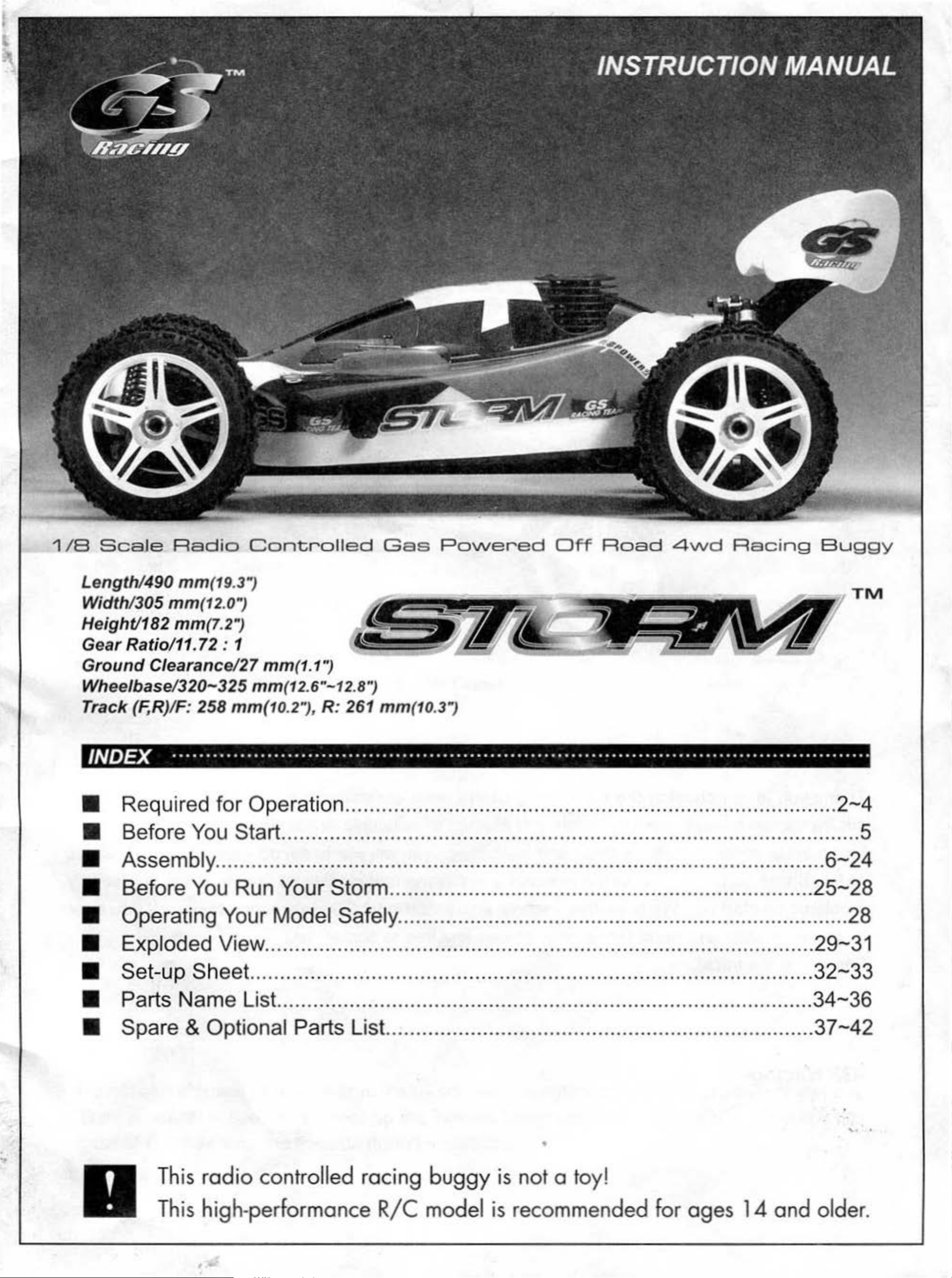
1
/B
ScaJe
Radio
Controlled
Gas
Po\Nered
Off
Road
4\N
d
Racing
Buggy
Length/490
Width/305
Height/182
Gear
Ground
Wheelbase
Track
Ratio/11. 72 : 1
(F,R)/F:
INDEX
mm
mm(12
mm
Clearance
/320-325
(7.2")
258
.......................................................................................................
• Required
II Before
You
(19.3")
.0")
/27
mm(12.6"-12.8'~
mm(1
for
Operation .................................................................................
Start
mm
(1.1")
0.2"), R: 261
mm
(10.3")
......................................................................................
.......
TM
.
2-4
...
5
..
- Assembly .....................................................................................................
• Before You Run Your Storm ......................................................................
6-24
25-28
• Operating Your Model Safely ........................................................................... 28
• Exploded View .................................... ....................................................... 29-31
II Set-up Sheet .............................................................................................
• Parts
• Spare & Optional Parts List.. .....................................................................
Name
List. .............................. ..........................................................
•
32-33
34-36
37-42
'.
.
Th
is
radio
Th
is hig h-performance
I
controll ed racing
R/C
buggy
model
is
not
is
recommen
o toy!
ded
for ages
14
and
older.
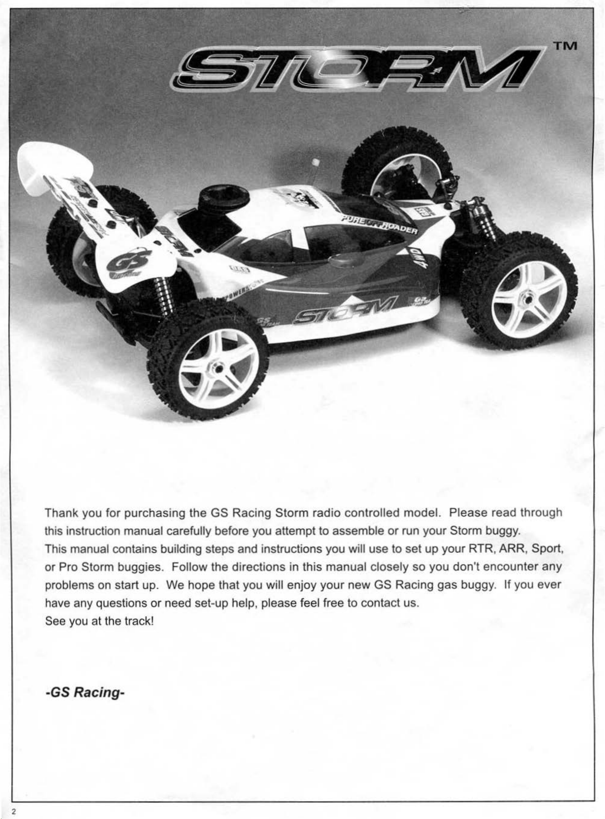
Thank you for purchasing the
GS
Racing
Storm
radio
controlled model. Please read through
this instruction manual carefully before you attempt to assemble
or
run your Storm buggy.
This manual contains building steps and instructions you will use to
or
Pro Storm buggies. Follow the directions in this manual closely
problems on start up. We hope that you will enjoy
set
have any questions or need
-up help, please feel free
your
new
to
GS
contact us.
Racing
See you at the track!
-GS Racing-
set
so
up your RTR, ARR, Sport,
you
don't
gas
encounter
buggy.
If
you ever
any
2
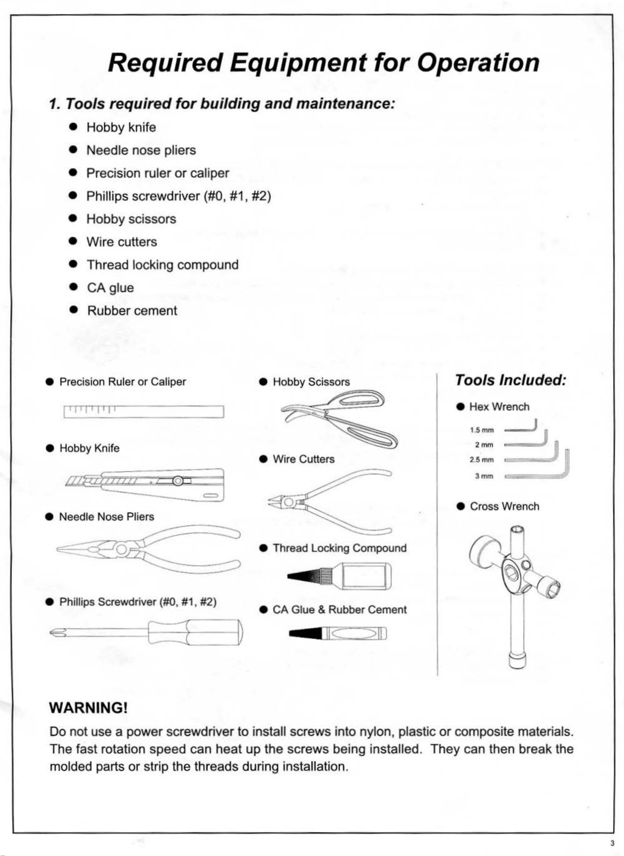
Required Equipment for Operation
1.
Tools required for building
• Hobby knife
• Needle nose pliers
Precision ruler or caliper
•
and
maintenance:
• Phillips
Hobby scissors
screwdriver (#0, #1, #2)
•
Wire cutters
•
Thread locking compound
•
CA
glue
•
•
Rubber cement
• Precision Ruler
or
Caliper
1'1'1'1'1'
e Hobby Knife
e Needle Nose Pliers
0
I
• Wire Cutters
e Thread Locking Compound
Tools Included:
•
Hex
1.
Wrench
5mm
2mm
J
e Cross Wrench
e Phillips Screwdriver (#0, #1, #2)
e
CA
Glue & Rubber Cement
WARNING!
Do not use a power screwdriver to install screws into nylon, plastic
The fast rotation speed can heat up the screws being installed.
molded parts
or
strip the threads during installation.
or
composite materials.
They
can then break the
3
. -
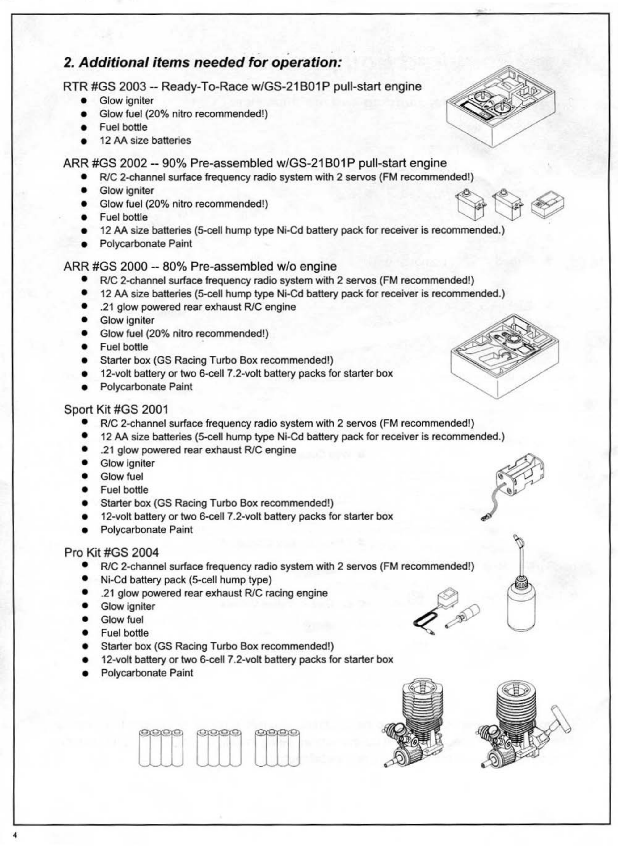
2. Additional items needed for operation :
RTR
#GS
• Glow igniter
• Glow fuel (20% nitro recommended!)
• Fuel bottle
•
12 AA size batteries
2003-
Ready-To-Race w/GS-21 801 P pull-start engine
ARR #GS 2002 - 90% Pre-assembled w/GS-21 801 P pull-start engine
• RIC 2-channel surface frequency radio system with 2 servos (F M recommended!)
• Glow igniter
• Glow fuel (20% nitro recommended!) . ""
•
•
• Polycarbonate Paint
Fuel bottle
12
AA
size batteries (5-cell hump type Ni-Cd battery pack for receiver is recommended.)
~
~
~
ARR
#GS
• RIC 2-channel surface frequency radio system with 2 servos (FM recommended!)
• 12 AA size batteries (5-cell hump type Ni-Cd battery pack for receiver
•
• Glow igniter
• Glow fuel (20% nitro recommended!)
• Fuel bottle
• Starter box (GS Racing Turbo Box recommended!)
• 12-volt battery
• Polycarbonate Paint
.21
2000 -- 80% Pre-assembled w/o engine
glow powered rear exhaust RIC engine
or
two
6-cell7
.2-volt battery packs for starter box
is
recommended.)
Sport Kit #GS 2001
• RIC 2-channel surface frequency radio system with 2 servos (FM recommended!)
• 12
AA
size batteries (5-cell hump type Ni-Cd battery pack for receiver
is
recommended.)
•
• Glow ignit
• Glow fuel
• Fuel bottle
• Starter
• 12-volt battery
• Polycarbonate Paint
.21
glow powered rear exhaust RIC engine
er
box (GS Racing Turbo Box recommended!)
or
two 6-cell 7 .2-volt battery packs for starter box
Pro Kit #GS 2004
• RIC 2-channel surface frequency radio system with 2 servos (FM recommended!)
• Ni-Cd battery pack (5-cell hump type)
•
• Glow igniter
• Glow fuel
.21
glow powered rear exhaust RIC racing engine
• Fuel bottle
• Starter box (GS Racing Turbo
• 12-volt battery
• Polycarbonate Paint
or
two 6-cell 7.2-volt battery packs for starter box
:s
Box
recommended!)
:2
4
Before You Start
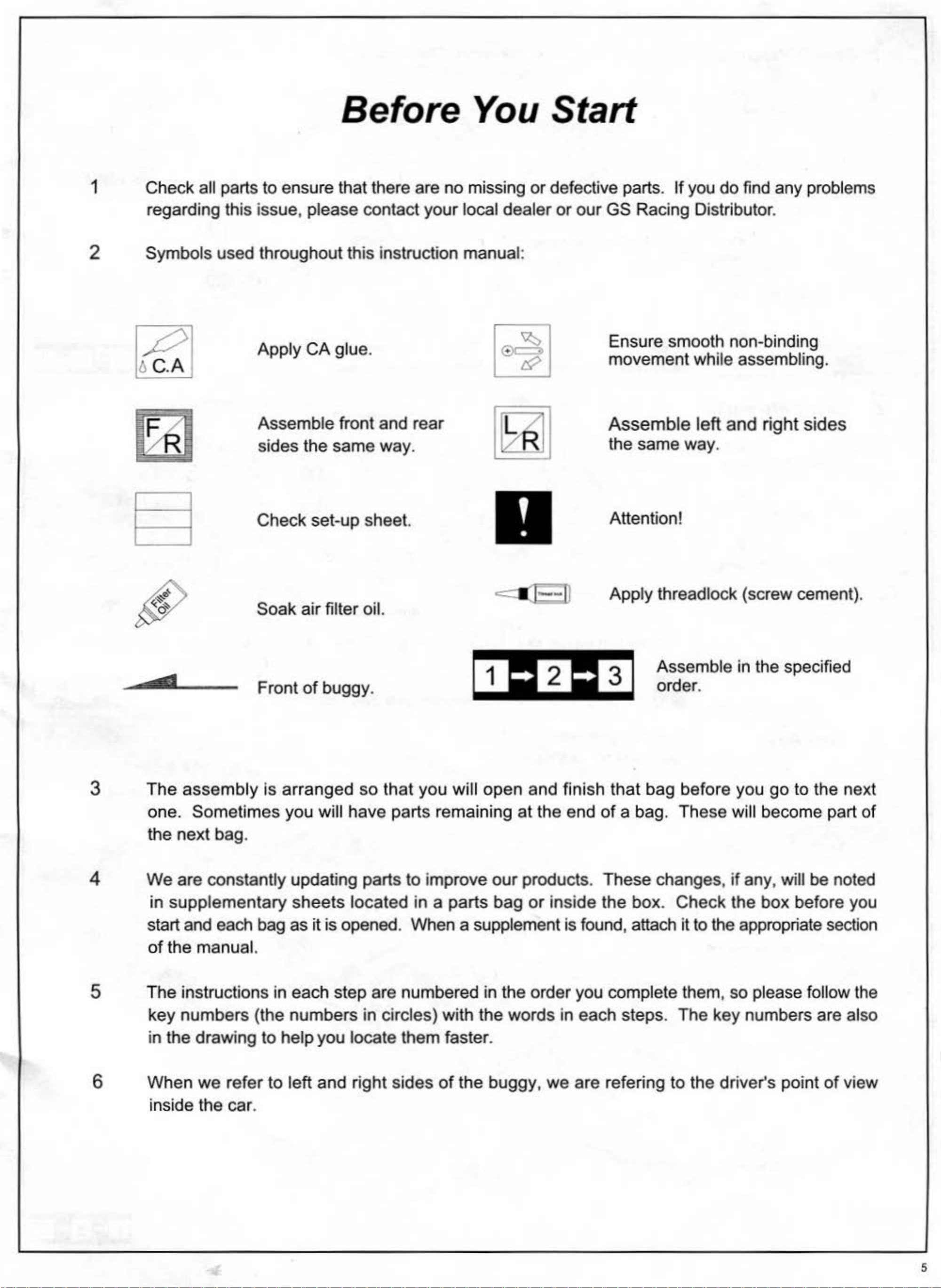
1 Check all parts to ensure that there are no missing
regarding this
issue
, please contact
your
local
dealer
2 Symbols used throughout this instruction manual :
Apply
1£1
Assemble
sides
~
CA
the
glue.
front
same
and
way
le~~
rear
.
BJ
or
defective parts .
or
our
GS Racing Distributor.
Ensure smooth non-binding
movement
Assemb
the same
If
you
le
way
do
find any problems
while assembling.
left
and
.
right
sides
3
___
, __
The
assembly
Check
Soak
Front
is
air
of
arranged
set-up sheet.
filter oil.
buggy
.
so
that
you
will
1
open
Attention!
Apply
3
and finish that bag before you
threadlock (screw cement).
Assemble in the specified
order.
go
to the
nex
t
4
one.
the next bag.
We
in
start and each bag
of
Sometimes
are constantly updating parts to i
supplementary
the manual.
you will
sheets
as
it
is opened. When a supplement is found, attach
hav
e parts remaining
located
mprove
in
a parts
5 The instructions in each step are numbered
6
key
in the
When
numbers
draw
we
ing to help you locate them faster.
refer
(the
to left
numbers
and right
in circles) with the words in
sides
of
the
at
the end
our
in
buggy, we
products.
bag
the
or
order you complete them , so please follow the
inside the
of
a bag.
These
box. Check
each
are refering to the driver's point
steps. The key numbers are also
These
changes,
it
to the appropriate section
will become part
if
any, will be noted
the
box
before you
of
of
view
inside the
car
.
5
1 Gear Differential
X3
4 x 4mm Set Screw
@
For
center (Flat surface)
X1
@
11. 4 x 10.x 0.3mm Shim
~
©
I I X3
5. 0-ring AS009 X
6.
6 x 10 x
7. 2.5 x 13.8mm Pin
2. 8x16mm Ball Bearin
2.5mm
X12
3
:..~hing
X3
2 Gear Differential
II
[II
m ® I
Build three differentials: front, center, and rear. ®
1==1
D Front -- 5000 wt.
Fill differential's using standard set up:
·~
~
~
·
~
3x
12mm RH/ST Screw
5. 0-ring AS009 X
© 6. 6 x 10 x
7. 2.5 x 13.8mm Pin
2. 8x16mm
2.5mm
Ba
ll Bearing
X12
3
::shing
X3
X3
/
@ For front and r
II
Fill oil
ear
X2
up
to where the differential
gear
--
pins cross.
@
Center --7000
Rear
-- 1000
X1
RH/ST 3x12mm
wt
w1.
3
GearBox
5 x 5mm Set Screw
{ffilmun
3.5x25mm RHIST Screw
2. 8x16mm Ball Bearing
\\l\
\til'.>
X2
xs
X4
X2
Build two gear boxes.
Mark gear boxes front and rear.
Apply threadlock!
\
Apply grease! m
@
RH/ST 3.5x25mm
6
15.
13.4x16x0.2mm Shim
RH/ST 3.5x25mm
~
LL:-----
~
·
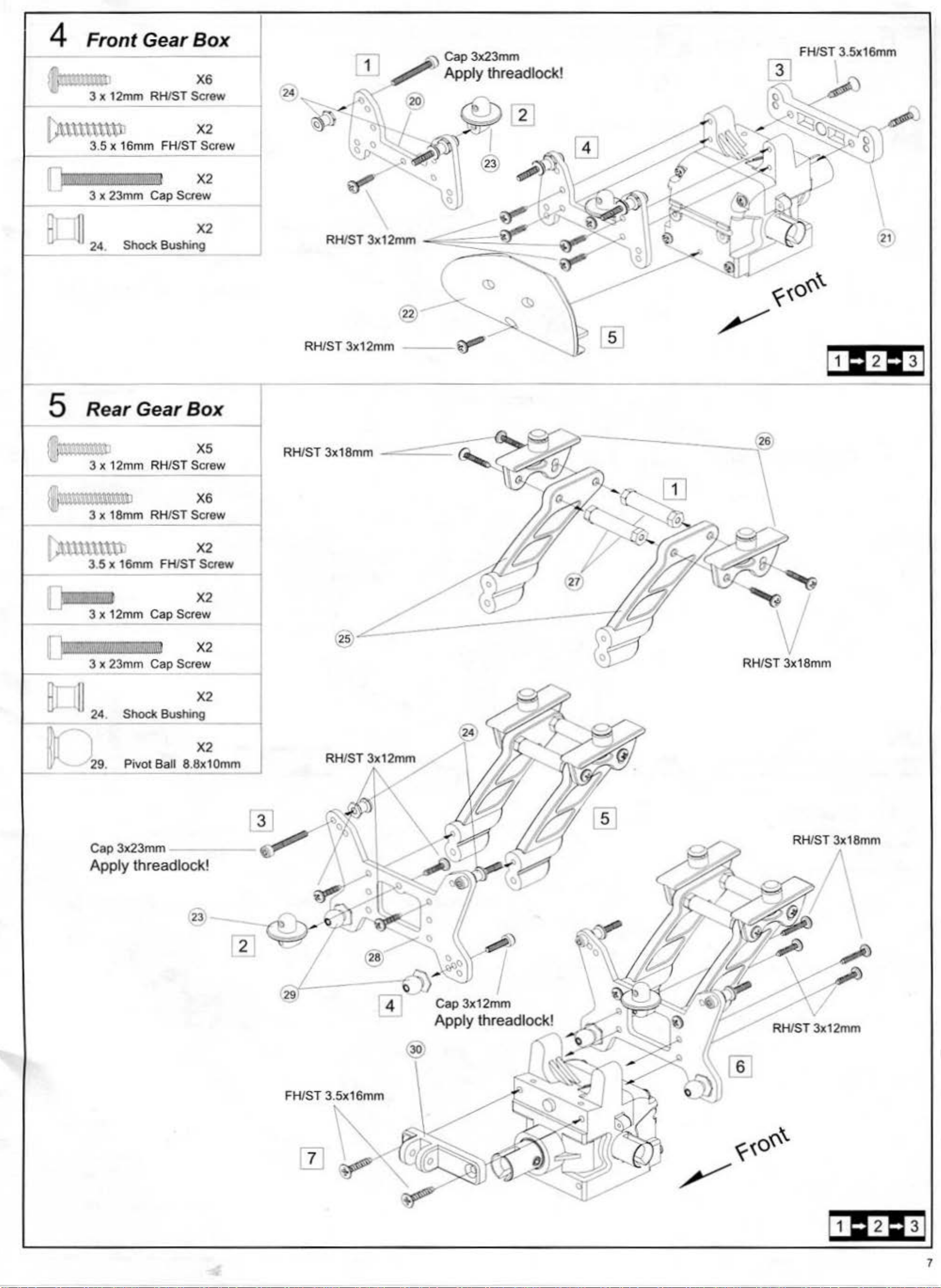
4 Front Gear
en,,
...,
Box
X6
..._
'J;( 12mm RHIST Screw
f'n~\U\t\.\11
II'-
1).:._:,
.5 x
16
mm
3
~n)lt:
3 x 23mm Cap Screw
.:·;
FHIST Screw
:&.
1
X2
x2
--1
24
--
11
. Shock S
24
ushi:
RHIST 3x12mm
-
--
~
·
~[
\
21
5]
5
If
...
!J\J""'
Rear
,.,"
~
-·;·
~"12
Gear
mm
RHIST Screw
~
3 x 18mm RHIST Screw
,l.Ul\l\ttt X
r
0·
~l.
" :
S
x 16mm FHIST Screw
x 12mm
3
..
e:rrc::::;
3 x 23mm Cap Screw
Cap Screw
:
a;:
ilt:
i X2
Box
xs
X6
2
X2
~
26
--
~
'v
RH/ST 3x18mm
ur
-,-
11
~
X2
24
.
Shock Bushing
X2
29
Cap3
Apply threadlock!
Pivot Ball 8.8x10mm
.
x23mm -
23
r 3]
RHIST 3x12mm
i
I
RHIST 3x18mm
II
FH/ST 3.5x16mm
~
]]
~
·
v
RHIST 3x12mm
7
6
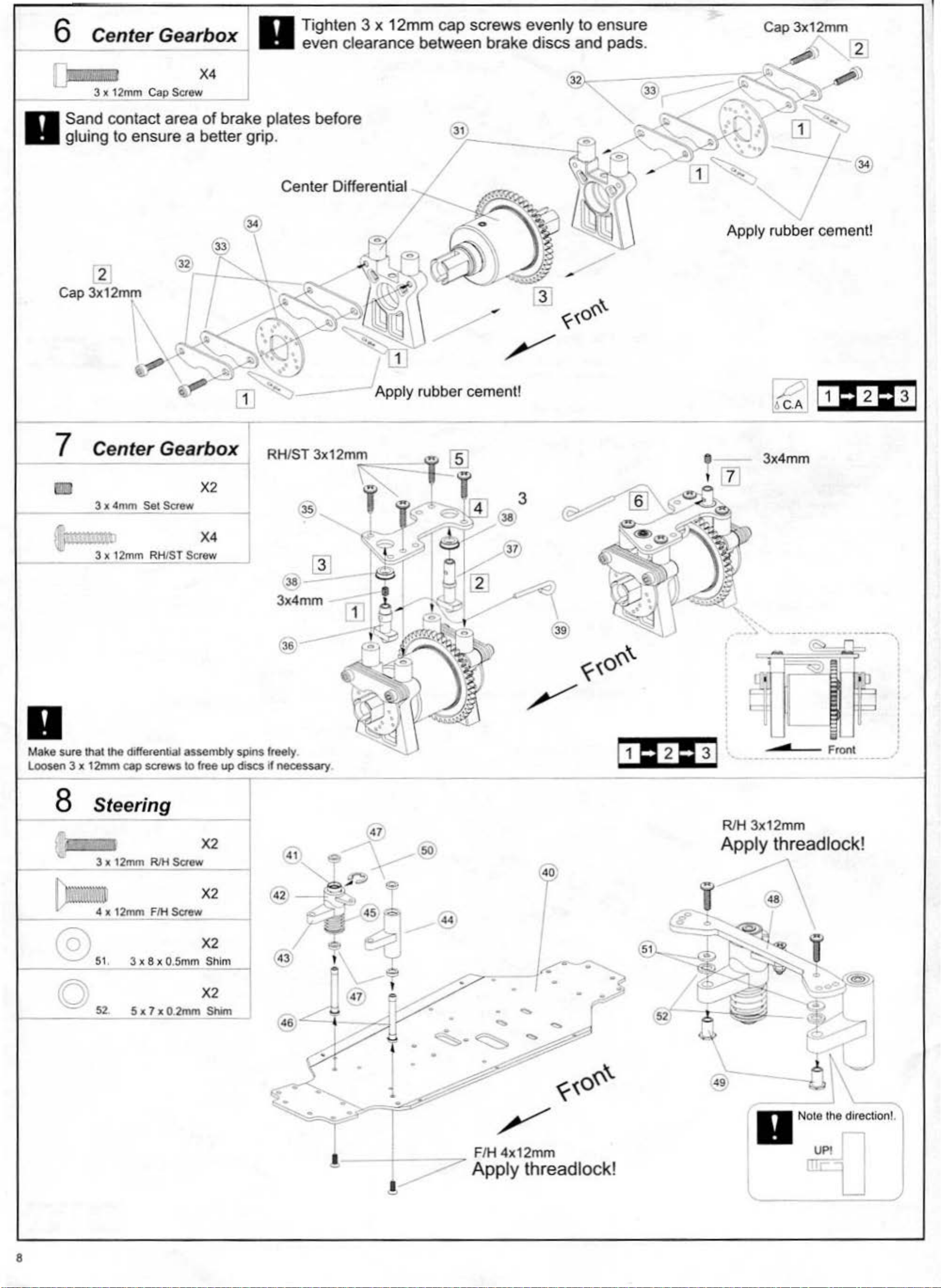
Center Gearbox
I
Tighten
even clearance
3 x
12mm
cap
between
screws
brake
evenly
discs
to ensure
and
pads
.
Cap
3x12
~
mm
-
2
_ _
II
Cap
_:
3 x
Sand c
gluing
....
2
3x12mm
12mm Cap
ontact
to
ensure a better
•
Screw
X
area
~
32
~
of
brake
plates
grip
before
.
I
.
ff
Center 1
34
D
erent1a
® \
_;·--.:.~.
. I
..,.
.......
31
-r-------1
-
@
-A~~
~G,"'-..
~
~
,..
~~..-'\...
;N
0
...
jJ
"'
...
Apply rubber cement!
7
------'
t
~··
" 3 x
3 x
4mm
,.,."':
12mm
Set
Saew
RHIST
X4
Scr
o:::ew.::...._
_
Apply rubber cement!
38
3
3
x4mm
----"
'
II
Make sure
Loosen 3 x
8 Steering
,.
'-
(:t:;a'J
---
c 52.
; t
lhallhe
12mm
NC
3 x
' 4 x
dJ!ferenbal
cap screws
'
12mm
12mm
RJH
FIH
3 x 8 x O.
S x 7 x 0.2mm Shim
aSS<>mbly
10
Screw
Saew
Smm
spins
free
up
discs
X2
--i
X2
~
~
im
X2
I
freely.
if
necessary
.........-¥
46
47
so
44
~
52
-
~
-
Front
RIH
3x12
mm
Apply threadlock!
48
~
8
•
!
•
l . .
•
•
•
,.,...
•
F
/H 4x12m
.?'
Apply threadlock!
m
,_-
49
II
Nolo lhe direction!. I
---
UP
!
~
l_j
/
9 Front Suspension
~
56
. 6.8 x 7mm Ball
55.
5x25
mm
Turnbuckle
)
54
. 6.8mm Ball End(S)
1 0 Front Suspension
1-
-
(ft)
58. E-clip E-2.5
X2
X2
X2
X4
-l
1
--
--
Assemble Right and
--
left
sides.
X2
1:1
•
Ill
11
!:]
X2
57. 3 x 34mm Hinge Pin
Front Suspension
X4
4 x12mm
Cap
Screw
Assemble one for each side.
Assemble Right and Left sides.
®
Cap4x12mm
V Apply threadlock!
R
X4
Knuckle Collar
X4
2. 8x16mm Ball Bearing
1 2 Front Suspension Assemble Right and
3
left
sides.
~
W..oll
o
~
@
.t:r.
Fl
.
~
'-.....
Cap
4x12mm
Apply threadlock!
0/)t
@
\
@
[S]
~
II
3 x
4mm
4 x
4mm
4 x 12mm Set Screw
.._
__
.J.--L-
69
. 3 x 36mm Hinge
L I I
68. 4 x 57mrn Hinge Pin
Set Screw
Set Screw
_
_1
X2
X.2
X2
X2
Pin
X2
L
4x12mm
I
9
13
Rear
Assemble Right and Left sides.
Suspension
0 72. 8.8 X 9mm
70. 8.8mm Ball End
71
14
•
. 5 x
Rear
3 x 4mm Set
SOmm
Suspension
Saew
Sal~
X4
~
X2
Turnbuckle
Rear toe-in can be adjusted
X2
by
®OJ
@
26mm
1:1
switching the adjusters!
@)
4x4mm
®·
----1.
@
X2
~
4 x 4mm Set
Ui!iiilllilu"'W
4 x 12mm Set Screw
l
oi
n.
79. 3 x 43mm Hinge P
0 I I
68.
3mm Stopper
4 x 57mm Hin
Saew
X2
X2
X2
X2
ge
X2
in
Pin
I
L
4x12mm
R
15
~
Suspension
4 x 15mm F/H
Saew
XB
10
0
F/
H
4x15mm
16 Chassis
3 x 12mm FIH Screw
~
X2
X8
RIH 3x12mm
Apply threadlock!
RH/ST 3x12mm
I.JWU
~
x
12mm F/H Screw
X2
0 X2
3mm Lock Nut
DQ
~
3.
Torque Rod
3 x 12mm
3 x 12mm
R1H
Screw
RHJST
a::
X2
X2
Screw
3mm Lock
nut
II
1 7
Check for
Rear
Suspension
Cap3x23mm
binding
X2
m
afte
r final
assembly
F/H4x12mm
of
all suspension parts!
F/H 4x12mm
FIH 3x12mm
Apply th readlock!
3mm Lock Nut
Cap
3x25mm
X2
-------
OJ
@
11
18
Assemble Right and Left sides.
Steering
~
85. 6.8mm
._I
_
0
~
~
0 3mmNut
__.
86
. 4 x 46mm Turnbuckle
56
.
7
.
3 x 16mm RIH Screw
Ball End
lli§l
6.8 x 7mm Ball
6.8 x
9mm
Pivot Ball
X4
I X2
X2
X2
X4
X2
®,
~
-@
___
_
RIH 3X16mm
,__
____
1-il
t_?
J
T
e
OJ
19
3mm
[)~~
SwayBars
Lock
X2
~~
Nut
·
~~~lmd~l
X2
L
1:1
24mm
_j
F=
l===
~~g;~C]
3mmnut --
(OQ~
~
t:::l
I
3mm Lock nut
QUICK
I "
Sk
~
d=:EE•
Using t
Changing the hole would give you either more
-
Aq~
he
middle hole is a good starting point.
@
\ SLOW /
MID
~
~
or
'\
__
less steering .
~
©.
-
•
3
3 x 4mm Set
5.8mm Ball End X
9. 5.l mm Ball End X
x 12mm Set Screw
Screw
0 X2
93. 5.8 x 4.6mm
0 94. 5.8 x 5.4mm
Ball
Piv~Ball
4
4
X4
X4
~OJ®~
~
3X4mm
Apply thread lock!
-
89
/ Set 3X12mm
oQ;
X4
®0
(§
~
[l]o>
~
~
@]
3X4mm
App
ly
threadlock!
®
00 X4
~
HI.\\'""'
[9]
II
92. 5.8 x
3 x 8mm RHIST Screw
3 x 15mm RHIST Screw
Do
•
not
11
mm Stabilizer Ba
over
tighten
X4
X4
3x8mm
ll
RHIST 3X8mm
RH/ST
[[j
screws.
The
sway
bars should
move
freely.
12
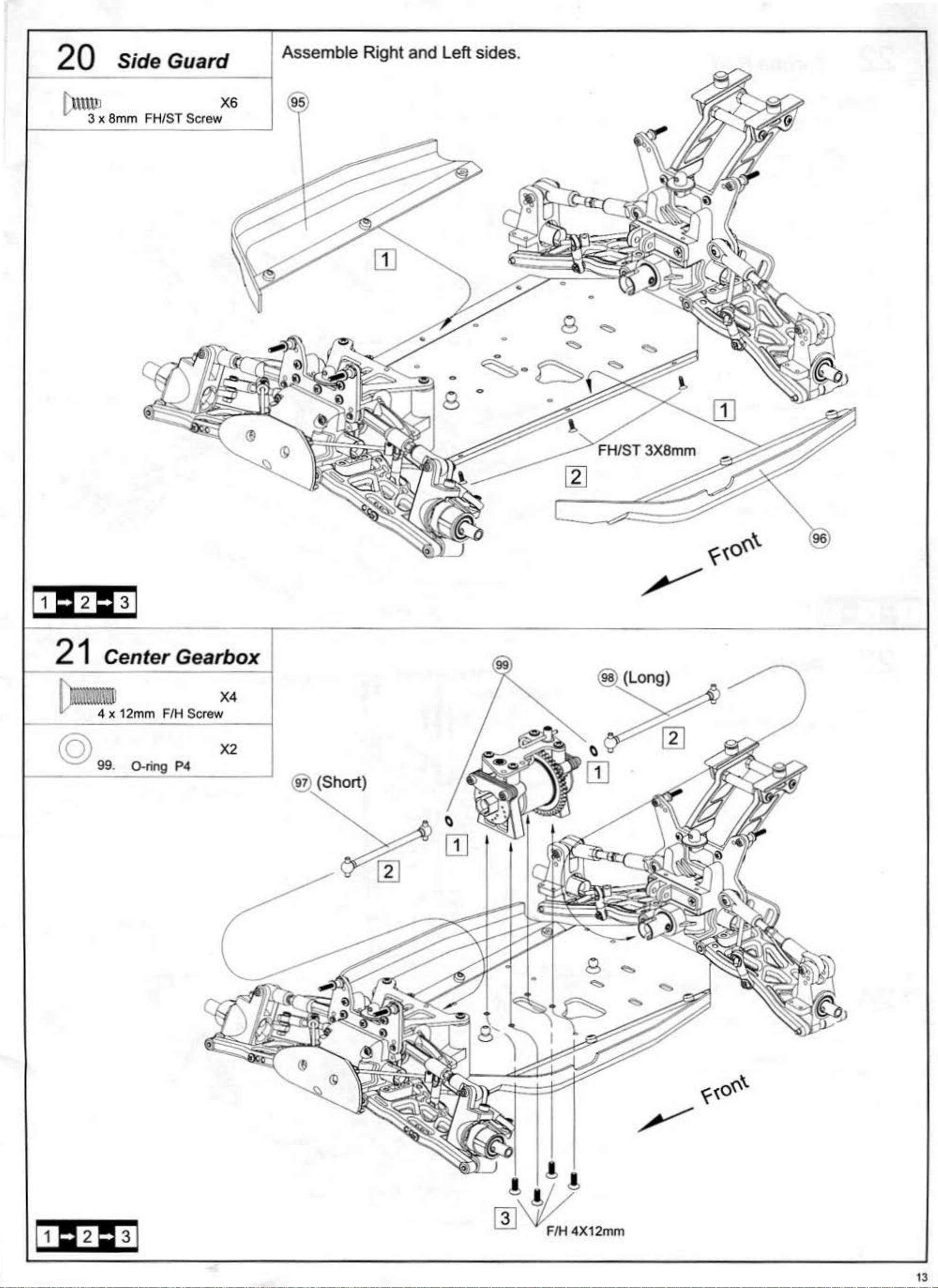
20 Side Guard
Assemble Right and Left sides.
~
3 x 8mm FH/ST Screw
X6
21
~
4 x 12mm F/H Screw
©
99. 0-ring P4
Center Gearbox
X4
X2
®.
(Short)
13
 Loading...