

GSN PATROL 101 Installation Manual
1 2 3 4 5
6 7 8 9 10
PATROL™- 101
WEATHERPROOF
CURTAIN PIR & MW
DETECTOR FOR
OUTDOOR USE
PATROL-101 combined
detector designed for use
in open, outdoor areas and
low-temperature environments
to -55°С.
PATROL-101 creates a
narrow protective curtain
allowing free movement within
the protected area without
triggering the alarm.
PATROL-101 with anti-mask
technology, to detect all types
of masking attempts.
PATROL-101 provides pet
immune detection up to 30kg.
FEATURES
· DUAL TECHOLOGY
PIR & MW
· QUAD ELEMENT
PYRO SENSOR
· BUILT-IN HEATER
· SHOCK SENSOR
· ANTI-MASK PROTECTION
· DOPPLER PULSE-COUNT
SELECTION (1-7)
· INDIVIDUAL PIR / MW/
ANTI-MASK SENSITIVITY
ADJUSTMENT
· IMMUNE TO PETS UP TO 30KG
· AUTOMATIC TEMPERATURE
COMPENSATION
· VISIBLE LIGHT DISTURBANCE
PROTECTION
· DOUBLE RFI/EMI PROTECTION
· WEATHERPROOF HOUSING
DETECTOR INSTALLATION
MANUAL
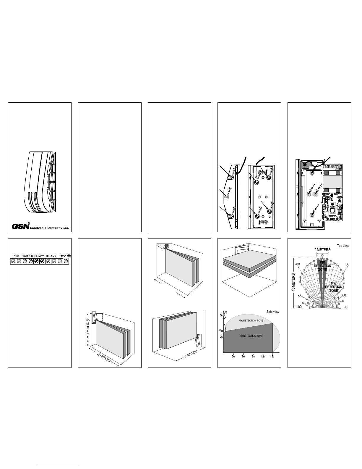
1. Run the installation wire
through the bracket wiring
hole.
2. Mount bracket onto the wall
and affix with screws, using
the knockouts.
Corner installation Wall installation
3. Run the installation wire
through detector back cover.
4. Mount back cover of the
detector to the bracket using
four screws.
5. Insert the PCB and connect
wires according to the
schematic.
6. Close front cover and affix
with screw.
TERMINAL BLOCK
CONNECTION
Terminals “+12V-“ – for
connection to the power
supply of the control unit.
Terminals “Tamper” –
for connection to a 24-hour
normally closed protective
zone in the control unit.
Terminals “Relay 1” –
PIR detector relay output.
Terminals “Relay 2”–
anti-mask relay output.
Terminals +12V- (H) – heater
power connects to external
12-16V/1A power unit.
IMPORTANT!
When connecting the heater,
take into consideration voltage
drop and power loss in cables.
PATROL-101 MOUNTING
OPTIONS
Detector can be installed
vertically or horizontally
(see illustration).
Recommended installation
height is 2.5m. Maximum
installation height is 5m.
* For installation over 3.5m,
mount the detector at an angle
of 20 degrees.
NOTE! Avoid installing detector
where direct sunlight can enter
the pyro sensor.
1
5
M
E
T
E
R
S
DETECTION AREA
11 12 13 14 15
16 17 18 19 20
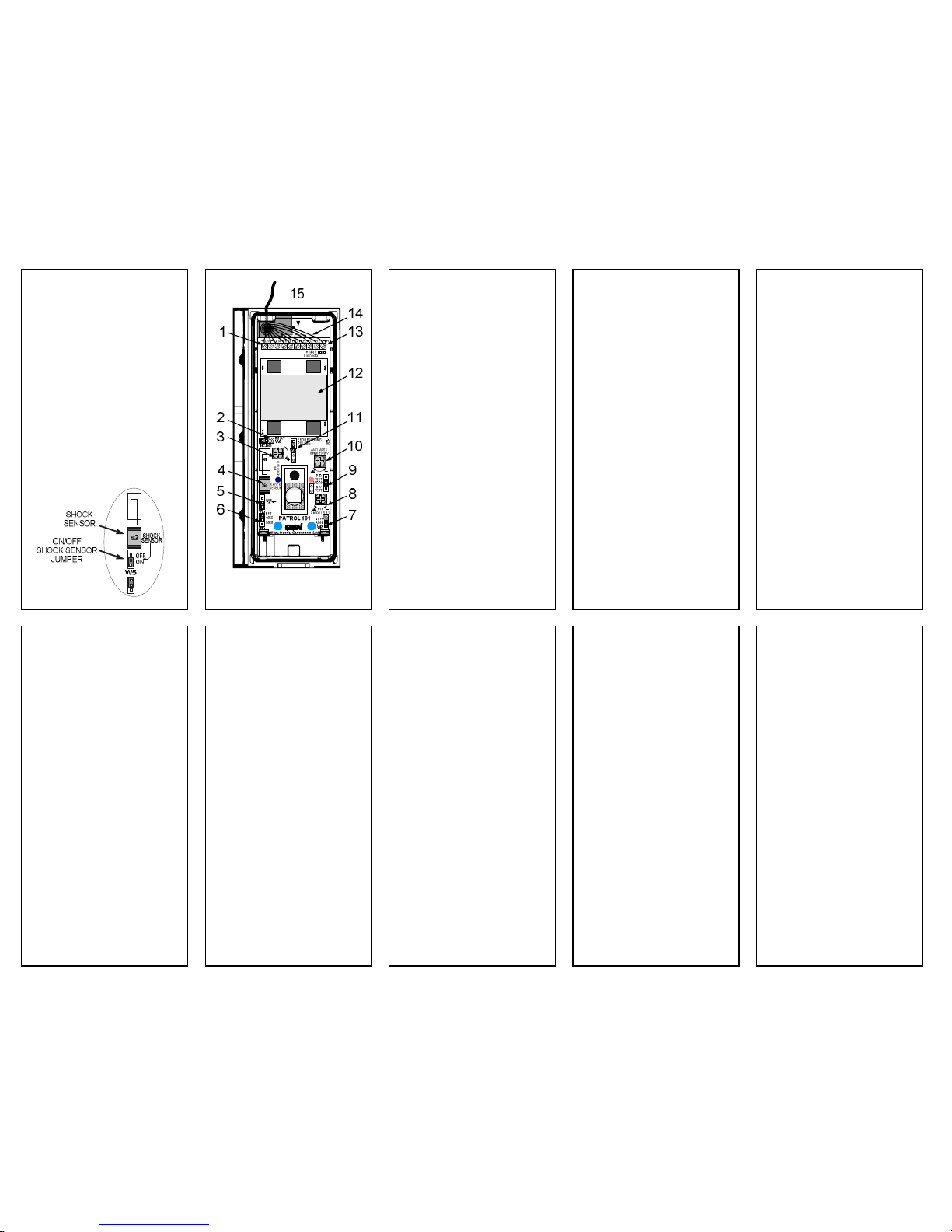
SHOCK SENSOR
PATROL-101 includes a shock
sensor that detects external
attack. Any physical impact or
attempt to separate the detector
from the wall will trigger an
alarm signal to the control
panel through the terminal
«TAMPER».
Jumper W5 enables/disables
the shock sensor.
· Jumper W5 On - Shock
Sensor activated.
· Jumper W5 OFF - Shock
Sensor disabled.
1. POWER SUPPLY CONNECTION
2. JUMPER TO SELECT NC/NO
3. MW SENSITIVITY
ADJUSTMENT
4. SHOCK SENSOR
5. ON/OFF SHOCK SENSOR
JUMPER
6. ANIMAL WEIGHT JUMPER
7. ON/OFF LED JUMPER
8. PIR SENSITIVITY ADJUSTMENT
9. OPERATING MODE SETTING
10. ANTI-MASK SENSITIVITY
ADJUSTMENT
11. PULSE PROGRAMMING
JUMPER
12. MW ANTENNA
13. HEATER POWER SUPPLY
CONNECTION
14. ANTI MASK RELAY OUTPUT
(RELAY 2)
15. PIR DETECTOR RELAY
OUTPUT (RELAY 1)
PIR ADJUSTMENT
1. Remove the front cover.
2. Connect the power and
wait for LED to stop flashing
(warm-up time 50 sec).
3. Set Jumper W1 to the
"PIR TEST" position, RELAY 1
is open.
4. Replace the cover.
5. Use the "PIR SENSITIVITY"
potentiometer to adjust the
PIR sensitivity, moving within
the protected area. The red
LED should flash with each
step.
MW ADJUSTMENT
1. Remove the front cover.
2. Set Jumper W1 to the
"MW TEST" position,
RELAY 1 is open.
3. Replace the cover.
4. Use the "MW SENSITIVITY"
potentiometer to adjust the MW
sensitivity, moving within the
protected area.
The blue LED should flash
with each step.
OPERATION MODE
1. Set Jumper W1 to "WORK"
position.
2. Set Jumper W6 according
to animal weight.
3. Replace the cover – LED
will blink. At the same time,
keep the detector field-of-view
clear, until the LED stops
blinking – the anti-mask
function will then be activated
correctly.
Use the “ANTIMASK
SENSITIVITY” potentiometer
to adjust anti-mask sensitivity.
4. Affix the cover with screw.
CHANGING RELAY
SWITCH CONNECTIONS
1. Disconnect the power.
2. Set Jumper W4 to "ON"
position.
3. Restore power.
PULSE-COUNTING METHOD
Selectable pulse count 1, 2, 3,
4,
5, 6 or 7 provides users with the
option of optimizing detector
sensitivity to suit the
environment, thus retaining
reliable performance at all times.
To adjust pulse count for
specific operating environments:
1. Remove Jumper W3.
The blue LED blinks indicating
that pulse counting has begun.
2. Replace Jumper W3 during
pause between LED blinking.
TECHNICAL
SPECIFICATIONS
Input voltage……………….9 – 16V
Current consumption:
In standby mode: …………...80mA
In alarm mode:……………..120mА
Heater input voltage….....12 – 14V
Heater current
consumption:……………….700mA
Microwave frequency:...10.525GHz
Anti-mask startup (boot)
period:……………..…… 50 ± 5sec
Adjustable mask
detection:……………….0.2 –20cm
Warm up period:…..……50 ± 5sec
Detection range:…...……15meters
Detection speed
range:………………..0.2 – 4 m/sec
Relay output:……………………….
………...NC/NO; 60V; 100mA; 16Ω
Tamper output:…...........................
……………..NC; 60V; 100mА; 16Ω
Anti-mask Relay output:…………..
………..NC/NO; 60В; 100mА; 16Ω
Anti-mask alarm activation
delay:…………………......40-60sec
Alarm period:…......................3sec
Reset time:………………..5 ± 1sec
Pulse counting:……...............1 – 7
Installation height:………..2.5 – 5m
Light immunity:……………………...
…………….no less than 30000 lux
Operating temperature range:
without heater ………–30°C +60°C
with heater ………....– 55°C +60°C
Storage temperature
range:....................– 60°C – +80°C
Protection rating………………IP65
RFI immunity: 30V/м
at a frequency range 30MHz-2GHz
EMI immunity……………..50,000V
Dimensions:………………………...
…………..55mm x 49mm x 153mm
Weight:…………….…………270gr.
WARRANTY:
GSN Electronic Company Ltd.
warrants the product to be free
from defects in materials and
workmanship under condition
of observance of service
regulations and to be repaired
or replaced under absence of
mechanical damages for a
limited period of five years
from the date of sale.
P/N: USMEPAT101REV.A
 Loading...