


User Manual for
GC0321, GC0641, GC1281
Applicable to software package Version 7.47 and up
Last Edited 03 October 2017
Before Attempting to connect or operate this product, please read these instructions in its entirety
This manual is intended to provide detailed technical specifications and explanations, to the basic
user as well as the more technically-minded person. This manual is a live document, and will be
updated often with new information. Please insure that you have the latest version, by checking our
website at: https://www.gsmcommander.com.
Changelog:
DS 03 October 2017 - Fixed specification table error
DS 09 June 2017 - Update error codes and content
DS 09 May 2017 - Update content (antenna info)
DS 20 April 2017 - Update content / IMEI number
DS 04 April 2017 - Fix errors and update content
SD 30 September 2016: - Fixed errors and updated content
DS 25 August 2016: - Updated contents table, fix errors and update content
HM 15 June 2016: - Updated contents table with missing references,fixed spelling errors.
HM 14 June 2016: - Amended operating parameters and description of settings.
HM 01 June 2016: - Added new Airdrive SMS config command, variable population strings.
SJD 25 July 2014: - Corrected General Status Message format.
SJD 05 July 2014: - Updated General Status Message format.

TABLE OF CONTENTS
Features.......................................................................................................4
Specifications................................................................................................5
System requirements.......................................................................................5
Dimensions...................................................................................................6
Installation....................................................................................................7
Environment...............................................................................................7
Power Supply...............................................................................................7
USB Port....................................................................................................7
SIM Card....................................................................................................7
Antenna.....................................................................................................8
Software Installation.....................................................................................8
Mounting..................................................................................................11
Optically - Isolated Digital Inputs.....................................................................11
Outputs....................................................................................................13
Temperature Sensor.....................................................................................14
Analog Input..............................................................................................15
Battery Input.............................................................................................16
Internal Battery..........................................................................................16
Expansion Unit...........................................................................................17
Dimensions of Expansion Unit..........................................................................18
Status LEDs...............................................................................................19
Testing the GSM Commander...........................................................................21
Commissioning Mode....................................................................................22
Configuration VIA PC......................................................................................23
Basics......................................................................................................23
Software Tabs............................................................................................24
Numbers Tab List A and B...............................................................................24
Messages Tab.............................................................................................24
Behaviour Statements Tab..............................................................................24
Settings Tab...............................................................................................25
Status Tab.................................................................................................25
IO Names Tab.............................................................................................26
Analog Scaling Tab.......................................................................................26
Lock Setup................................................................................................26
Configuration via SMS.....................................................................................27
Set Administrator number..............................................................................27
Clear Administrator number...........................................................................27
Check Administrator number...........................................................................28
Check Airtime............................................................................................28
Add a Number to the list...............................................................................28
Remove a Number from the list.......................................................................28
Enable/Disable statements.............................................................................28
Override GPRS Settings.................................................................................29
Reset GPRS................................................................................................29
IMEI Number..............................................................................................30
Switch SIM card..........................................................................................30
Reset GSM Commander.................................................................................30
IF-THEN Behaviour statements.........................................................................31
Supported IF Conditions................................................................................31
Supported THEN Actions................................................................................37
Multiple Actions to a Single IF Condition..............................................................39
Message Parameters.......................................................................................40
Variables.....................................................................................................41
Timed operations..........................................................................................41
Prepaid Airtime voucher loading.......................................................................42
Serial port...................................................................................................42
RS232 Configuration.....................................................................................43
Serial Functionality......................................................................................43
© Polygon Technologies. All rights reserved Page 2

Firmware Updates.........................................................................................47
Low power / Battery Operation.........................................................................48
4-20mA Analog Application Note.......................................................................49
Special Settings............................................................................................50
NITZ Timekeeping........................................................................................50
Set Variable via SMS.....................................................................................50
Jamming Detection......................................................................................50
Application Examples.....................................................................................51
Example 1: Periodic message..........................................................................51
Example 2: Monitor alarm..............................................................................51
Example 3: Control an appliance......................................................................52
Example 4: Gate / garage door opener..............................................................52
Example 6: Set an Output as a flag...................................................................52
Example 5: Contact to Contact relay.................................................................53
Troubleshooting............................................................................................54
GSM Commander setup software reports............................................................54
GSM Commander setup software reports “Hardware not detected”............................54
GSM Commander does not send any SMS messages / Error codes................................55
GSM Commander does not display the Airtime value..............................................56
GSM Commander does not respond to Voice Calls..................................................56
Guarantee...................................................................................................57
Disclaimer / Important Notice...........................................................................57
Important Notice...........................................................................................57
Manufacturer Contact details...........................................................................58
© Polygon Technologies. All rights reserved Page 3
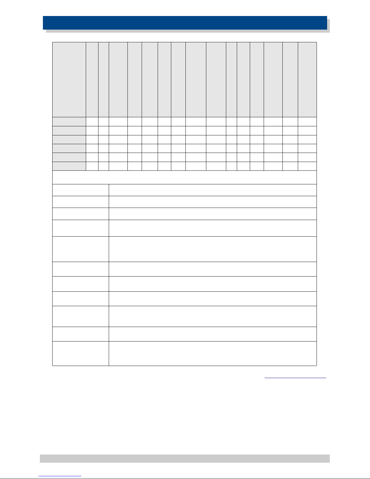
1. FEATURES
* Only able to view the current status and history (on Historian package) via Airdrive ( http://www.airdrive.co.za).
** 3G capable GSM Commanders are capable of operating on 3G networks, where 2G is not available. Most countries can
operate on 2G without any issue.
© Polygon Technologies. All rights reserved Page 4
Model
On-board Inputs
On-board Outputs
Max Number of Statements
Max number of Messages
Max Length of Messages
GPRS Enabled
3G Capable**
Temp probes Supported
Analog Inputs
Battery / Power Monitor
Extended Analogs
DTMF Decoder
SIM Card Slots
GC0321 2 2 12/12 32 256 64 127 YES* NO 2 1 YES NO NO Single
2 2 12/12 32 256 64 127 YES* YES 2 1 YES NO NO Single
GC0641 2 2 22/22 64 512 128 127 YES NO 2 1 YES YES YES Single
2 2 22/22 64 512 128 127 YES YES 2 1 YES YES NO Single
GC1281 2 2 32/32 128 512 128 127 YES NO 2 1 YES YES YES Dual
2 2 32/32 128 512 128 127 YES YES 2 1 YES YES NO Dual
Matrix Feature Descriptions
Model The code used to define between the various units functionality and capabilities
On-board Inputs The number of inputs provided on the base unit itself
On-board Outputs The number of outputs provided on the base unit itself
The maximum total number of messages that can be programmed into the unit
GPRS Enabled
The number of temperature probes the base unit can accept
Analog Inputs
Expandable
Inputs / Outputs
Max number of Phone
Numbers
GC0321 3G
GC0641 3G
GC1281 3G
Expandable
Inputs/Outputs
The maximum total number of Inputs/Outputs that can be expanded to by fitting
expansion units
Max Number of
Statements
A measure of the amount of complexity that can be programmed into the unit.
Each statement is of the form IF <ABC happens> THEN <do something>, such as IF
Input 1 goes Active, THEN send “Generator Tripped” to “0831231234”
Max Number of
Phone Numbers
The maximum total number of phone numbers that can be programmed into the
unit
Max Number of
Messages
Max Number of
Statements
The maximum total number of behavior statements that can be programmed into
the unit
If yes, the unit is able to be registered onto the AirDrive Platform which can allow
it to log it's status, log it's events,have remote config and remote output control
via GPRS.
Temp Probes
Supported
The number of analog Inputs available. By default this is a 0-10V analog port. Inconjunction with a 470 Ohm resistor it can be used for a 4-20mA port as well. See
more information in the Analog port section.

2. SPECIFICATIONS
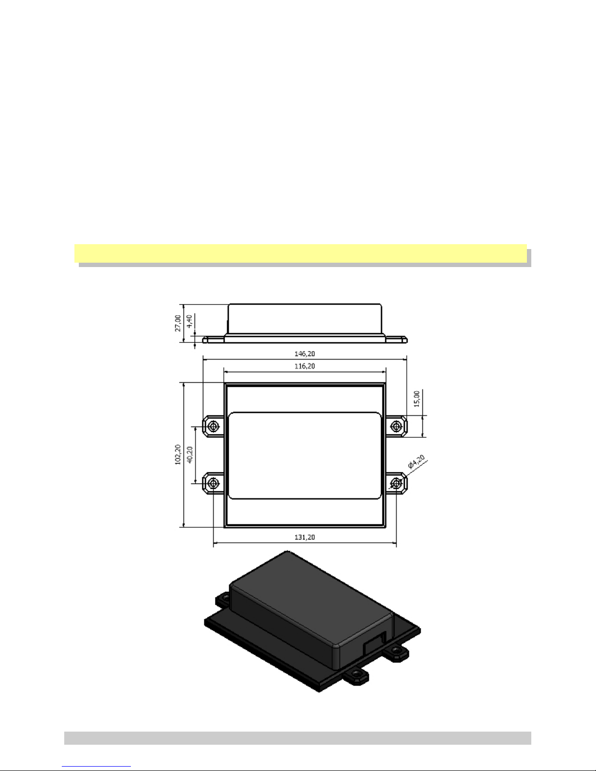
Weight 200 grams
Dimensions
146.2 x 85,2 x 27 mm
Power Supply
12-24V DC via DC Jack
Power Consumption ~ 2.5W
Current Consumption
~ 60mA at idle (no inputs or outputs active)
Operating Temperature -30°C to +60°C
Storage Temperature -30°C to +80°C
Digital Inputs
Opto-isolated. Inputs draw 2 - 45mA, depending on
voltage. Can accept any DC signals of any type,
including:
➢ Dry Contacts
➢ Open Collector (NPN)
➢ Closed Collector (PNP)
➢ DC Voltage (3 - 20V)
Digital Outputs
2 x SPDT Relay Contact rating: 8 Amp DC (10 - 48V) or
4 Amp AC (110 – 250V). Expandable to maximum of 32*
Analog Inputs 1 x Analog input 8 bit resolution 0-10.8V / 4-20mA
IO Connector type Pluggable terminals
GSM-850/900MHz Output Power Class 4 +33dBm (2W)
GSM-850/900MHz Sensitivity -107dBm
GSM-1800/PCS-1900 Output
Power
Class 1 +30dBm (1W)
GSM-1800/PCS-1900 Sensitivity -106dBm
* Model Dependent (See Feature Matrix in Section 2 )
3. SYSTEM REQUIREMENTS
The setup software requires a PC with the following specifications:
Operating system Windows 2000 / XP / Vista / 7 / 8 /10
Computer Architecture Pentium 2 or higher IBM compatible PC
Disk space 20MB
Ports 1 x free USB port
© Polygon Technologies. All rights reserved Page 5
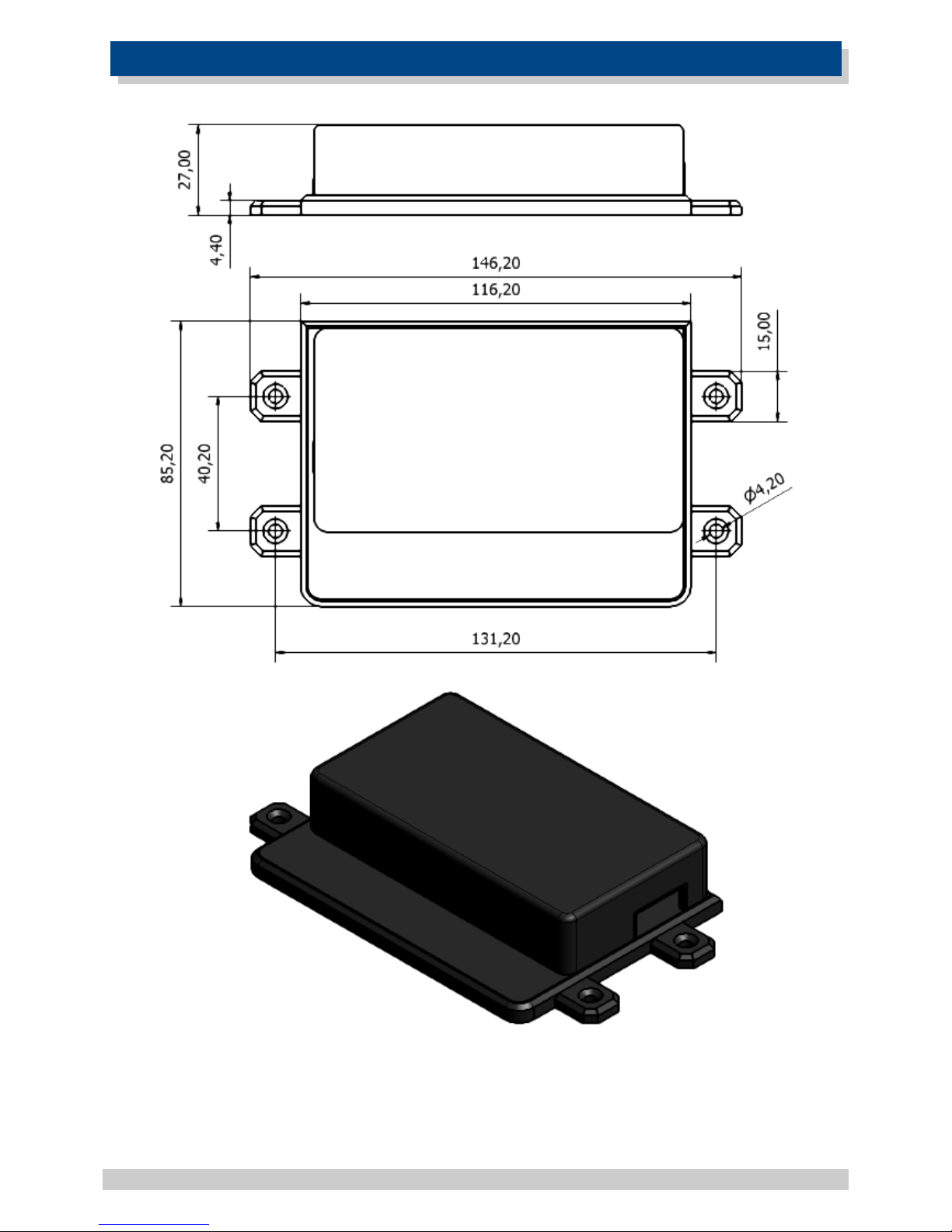
4. DIMENSIONS
© Polygon Technologies. All rights reserved Page 6
5. INSTALLATION
5.1. Environment
Due to the make-up of the GSM Commander and it's electronics, we STRONGLY advise that it not be
installed in close proximity to a variable speed drive or any other electrically noisy equipment. DO
NOT install the GSM Commander into a metal enclosure unless an antenna is mounted on the outside
of the enclosure.
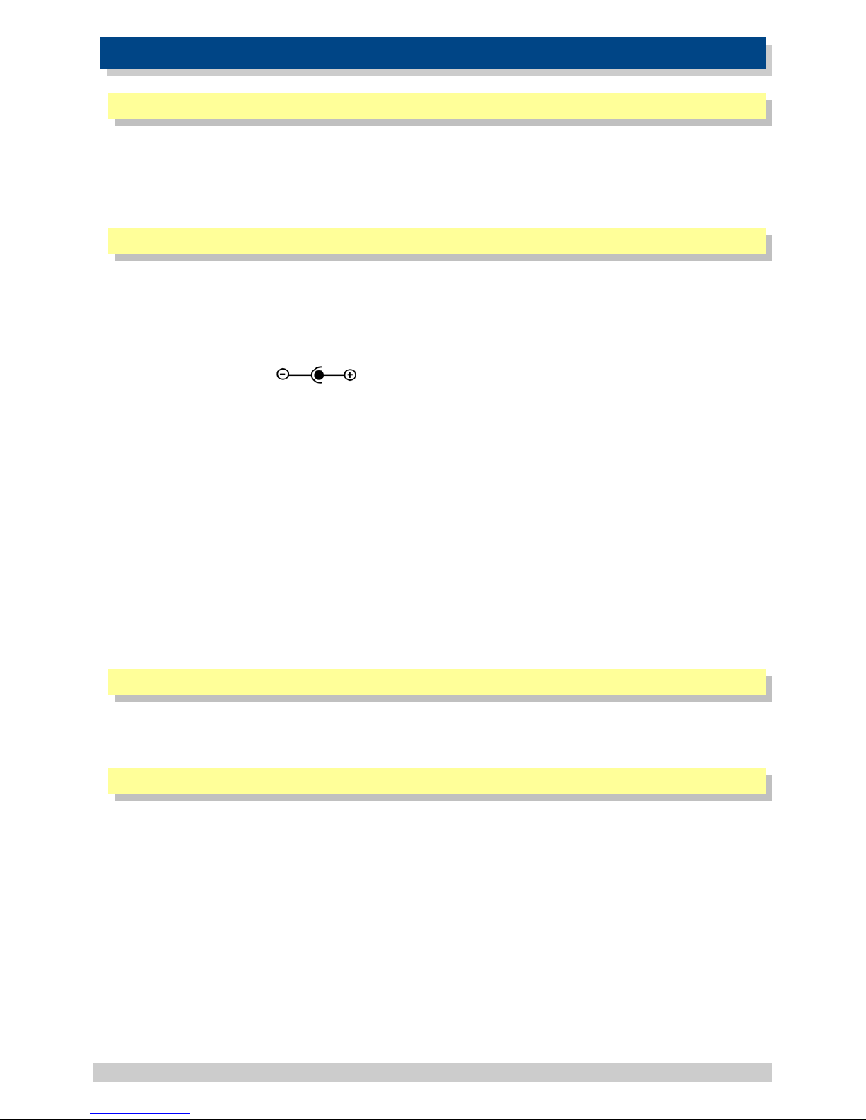
5.2. Power Supply
The GSM Commander has a 2.1mm DC jack connector where a power supply must be connected. The
power supply should have the following specifications:
• Output Voltage: 14V nominal
• Output Current: 0.5A
• Polarity:
A suitable power supply is supplied with the retail product.
Please Note: It is advised to use a 14V Switching Power Supply if more than one Expansion Unit is
connected to the GSM Commander.
In industrial applications, it is advised that the GSM Commander be installed into its own
metal housing and be powered from a separate power supply with a DC Filter. (As opposed to
sharing one with other equipment).
Please Note: While the GSM Commander has fairly rugged internal power supply circuitry, no
special provision for lightning protection is made. If the GSM Commander is used in an area that is
prone to thunderstorms, it is advisable to use a commercially available lightning suppressor (The
same applies to inputs or outputs that are connected to wires longer than 2 or 3 meters). The
guarantee does not cover damage resulting from lightning strikes! The GSM Commander can
operate reliably from voltages in the range of 12 to 24V DC.
5.3. USB Port
The GSM Commander provides a USB port that connects to a PC using the supplied USB cable. This
allows the PC to configure the unit.
5.4. SIM Card
The GSM Commander accepts a standard GSM SIM card from any network. The SIM card may be
prepaid or on contract. If the SIM Card is purchased as part of a prepaid plan, ensure than the card
is loaded with sufficient airtime.
WARNING: DO NOT Insert or remove the SIM card while the GSM Commander is powered!!
Note that airtime will decrease with every SMS that is sent from the unit. The unit can
automatically detect if the airtime is running low. It is user's responsibility to make sure than the
airtime is topped up. See your network's documentation on how to purchase and load airtime.
The SIM card is fitted into the back of the unit, as indicated by the legend on the enclosure. The SIM
card will click into place and is removed simply by pressing against it. The card will pop out with a
“click” sound, ready to be completely removed.
© Polygon Technologies. All rights reserved Page 7

Before you install your SIM Card:
• Install the SIM card into a normal cellular phone
• Verify that there is no SIM PIN enabled (The phone must not ask for a PIN when switched on with
this SIM card inside). If the phone does request a PIN, you need to enter the correct pin so that
the phone can start, and then disable the SIM Card PIN. See your cellphone documentation on
how this can be done.
• Verify that you are able to send an SMS message.
The SIM card will now work with the GSM Commander.
Please Note: If you are using a prepaid SIM card, be aware that if the SIM card has not produced a
billable event on the network for a long period of time (typically 3 months), the card will be deactivated by the network, and the SIM card then becomes useless. It is strongly recommended that
you configure the GSM Commander to send you an SMS every now and then (once or twice a week)
so that your SIM card remains active on the network.
The GSM Commander can ONLY check the airtime of a PREPAID SIM card.
5.5. Antenna
The GSM Commander is supplied with a basic antenna operating in the correct frequency band for
your area / country. Connect the antenna to the GSM Commander securely. Verify, using a cellphone,
that there is sufficient signal at the proposed installation site. On a phone with a 4 or 5-bar signal
strength indicator, you should have at least 1-2 bars of signal.
If the signal is too weak, the GSM Commander may have trouble sending or receiving SMS messages.
Low signal can also affect the unit and might result in more data charges (using the GPRS gateway).
In these cases, try and find a better location, or order one of our special antennas.
If you are outside South Africa, you may require a different antenna.
The frequency bands are:
➢ 2G : 850 / 900 / 1800 / 1900MHz
➢ 3G : 800 / 850 / 900 / 1900 / 2100MHz
Your network will be able to tell you which frequency band(s) are in use. Contact your local
electronics supplier about antennas that operate in your area.
Feel free to contact Polygon Technologies with your request for a special antenna.
5.6. Software Installation
The latest software is supplied on a CD (where applicable) with the product and is also available to
download from our website for free at https://www.gsmcommander.com.
We do recommend downloading the latest version from our website.
The setup program (on the CD) will start automatically, or if the autorun feature is not enabled on
your PC, you may run the “setup.exe” executable file on the CD to start the setup process. The
software has been tested to work on Windows XP, Windows Vista, Win7, Win8 and Win10.
The setup process for Windows 7 has been documented here, but the process is similar in the other
versions of Windows.
© Polygon Technologies. All rights reserved Page 8
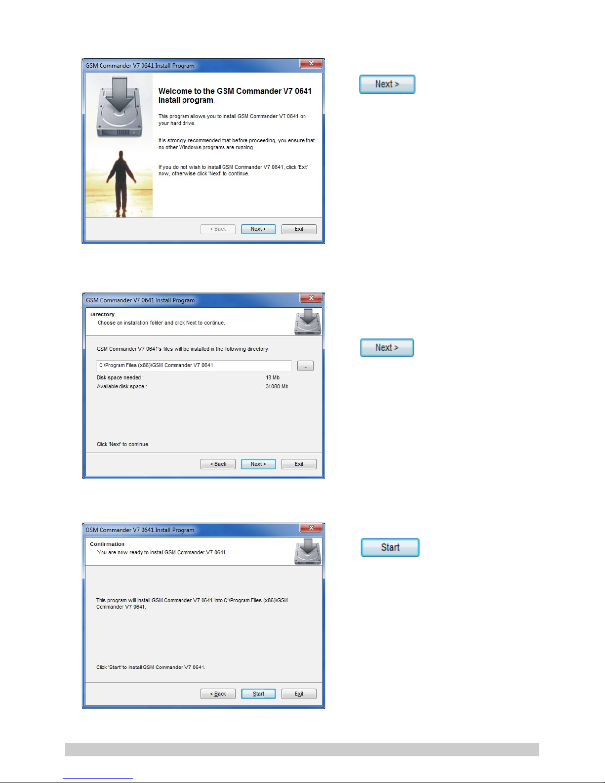
Screen 1:
Click
Screen 2:
It is recommended that you leave the
install path at the default location.
Click
Screen 3:
Click
© Polygon Technologies. All rights reserved Page 9
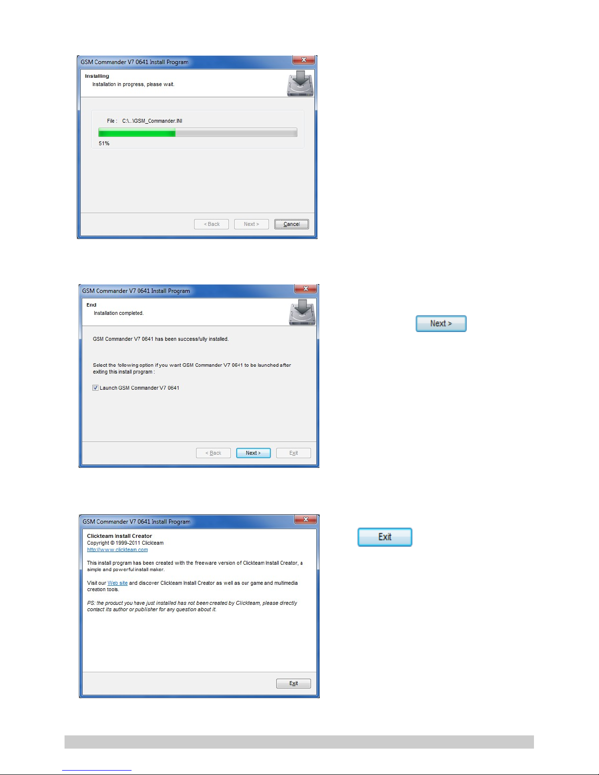
Screen 4:
Installation is in progress.
Screen 5:
Installation has been completed
successfully. Click
Screen 6:
Click
© Polygon Technologies. All rights reserved Page 10
5.7. Mounting
The GSM Commander is housed in a very durable ABS casing which has 4 protruding tabs, which
allows it to be mounted firmly to any surface by means of a screw. There is also a DIN-rail mounting
kit available separately.
Please note: The GSM Commander is not water- or weatherproof. The GSM Commander must be
mounted indoors, or inside an appropriate IP65-rated weatherproof enclosure. The guarantee does
not cover damage resulting from water ingress! DO NOT mount the GSM Commander inside a steel
cabinet, unless you also mount a separate antenna on the outside of the cabinet.
5.8. Optically - Isolated Digital Inputs
The GSM Commander itself provides 2 signal inputs. The number of inputs can be expanded by the
addition of Expansion modules, up to a maximum of 32 inputs*. Each of these inputs have 4
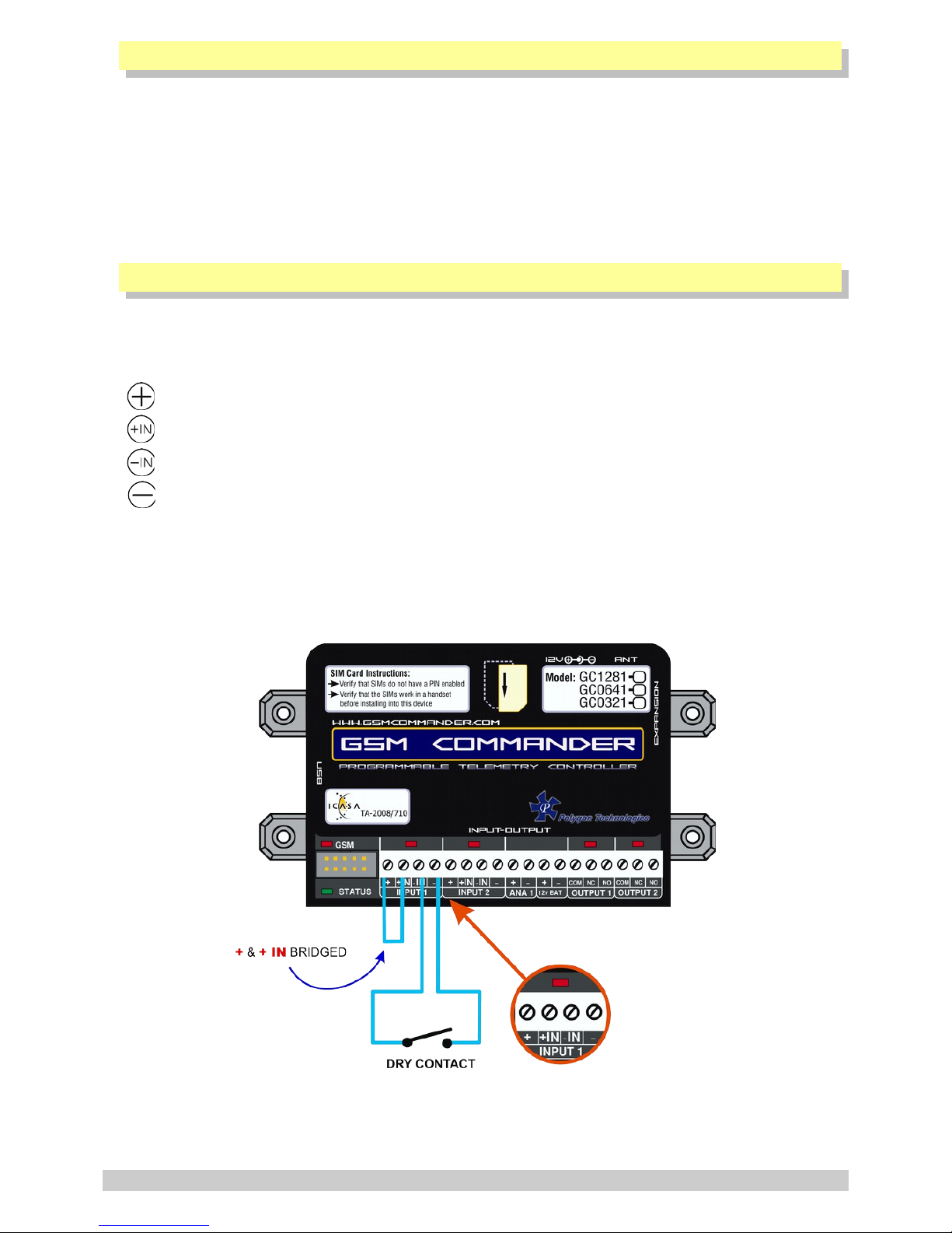
terminals associated with them:
Internal positive supply
Positive input
Negative input
Internal negative supply
To connect a switch or contact to an input, simply connect the switch between the - and -IN
terminals, and a wire between the + and + IN terminals. The reverse is just as suitable, i.e. that
you connect a wire between - and -IN and place the switch between + and +IN.
* Model Dependent (See Feature Matrix in Section 2)
© Polygon Technologies. All rights reserved Page 11
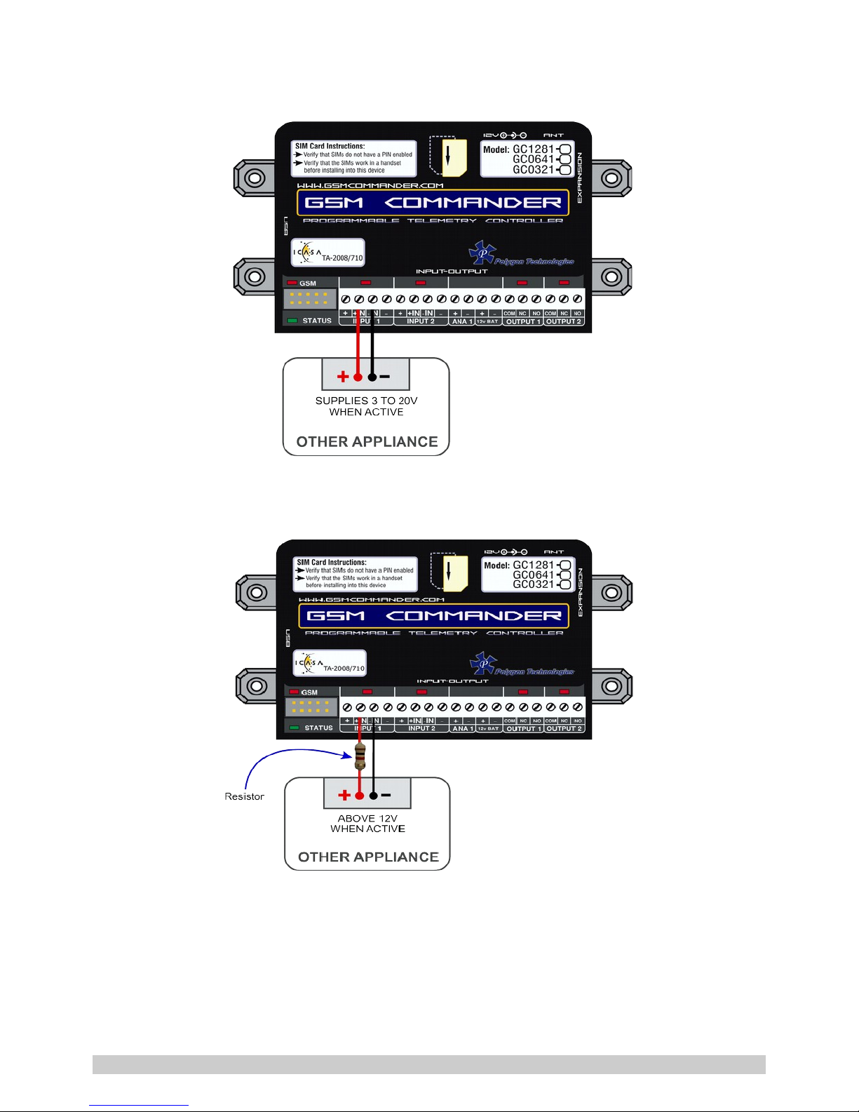
You may need an input to activate when power is supplied from some other unit. A good example
will be a burglar alarm that applies power to the wires going to the siren. In such a case, it will be a
simple matter of connecting the positive wire to the +IN input, and the negative wire to the –IN
input.
Please keep in mind that these inputs are designed for 3V to 20V operation. If you require to connect
a voltage above 20V to these terminals, you should connect a resistor in series with the input, as
shown below.
Input Voltage range Required Series resistor:
20V – 40V DC 1K ohm
The + and – terminals are connected to the input power supply of the GSM Commander.
If the power supply is 14V, the voltage at the + and – terminals will be slightly less at about 13.8V
(due to an internal series diode for reverse polarity protection).
© Polygon Technologies. All rights reserved Page 12
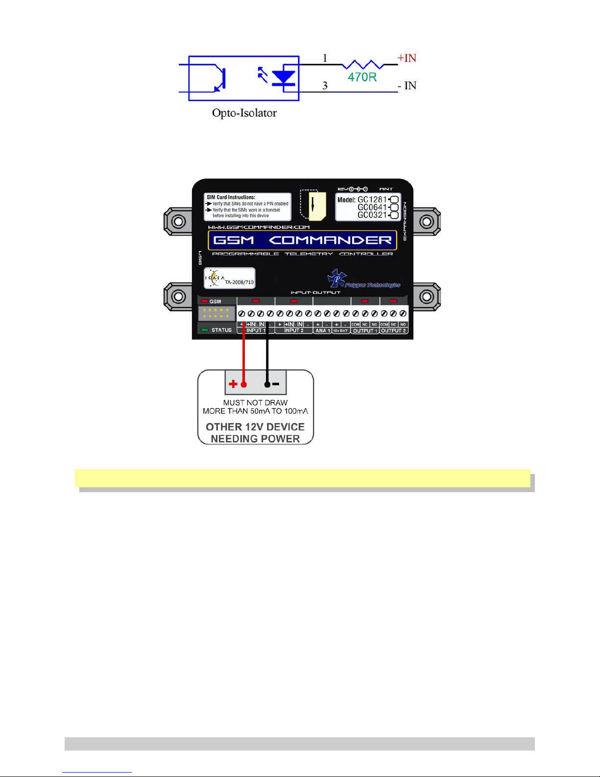
Here is a schematic of the input circuit used on the GSM Commander:
Drawing power for external hardware from the power terminals on the input:
One should not attempt to draw more than 50-100mA in total from the power terminals at the inputs
on the GSM Commander. For each expansion unit, the same applies.
5.9. Outputs
The GSM Commander itself provides 2 x 8A (DC) Relay outputs. The number of outputs can be
expanded by the addition of Expansion modules, up to a maximum of 32 outputs*. Each of these
inputs each have 3 terminals associated with them:.
Each of these inputs each have 3 terminals associated with them:
COM – Common Terminal
N/C – Normally Closed Terminal
N/O – Normally Open Terminal
When the output is off, the COM and N/C terminals will be internally connected to each other.
When the output is on, the COM and N/O terminals will be internally connected to each other.
Note that there are small LED indicators above the output terminals, that will show if the output is
ON or OFF (if the LED is on, then the output is also on).
* Model Dependent (See Feature Matrix in Section 2)
© Polygon Technologies. All rights reserved Page 13
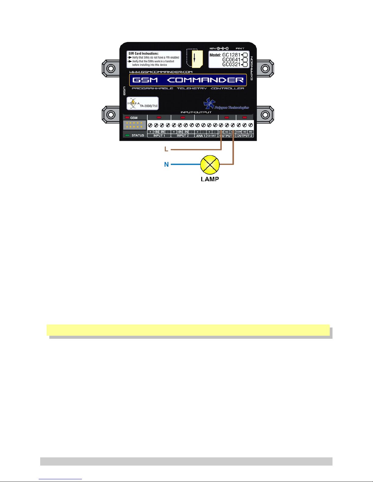
In the picture below, the output is connected so that the lamp will light up when the output is on.
This output can be used to control devices and appliances, and is rated for 8A DC. It may be used to
control most types of electrical loads, excluding AC motors above 500W.
Here are some examples of things you CAN directly switch on and off using the outputs on the GSM
Commander:
• Gate motors and any other motor less than 500W
• Mains Lights (energy savers, incandescents, halogens) (maximum 750W)
Here are some examples of things that you can NOT directly switch on and off using the outputs on
the GSM Commander:
• Ovens, Heaters, kettles
• Pumps and motors above 500W
Please note: Keep in mind that if required, the above loads can easily be switched on and off using
an externally connected relay or contactor.
5.10. Temperature Sensor
One can connect 2 temperature sensors to the GSM Commander (at the expansion port via a
temperature interface module) to measure temperature and allow the GSM commander to perform
certain tasks if the temperature falls above or below a certain point. The sensor provides an
accuracy of 2°C.
The temperature sensor (with 2m, 4m or 8m lead) and temperature interface is available from
Polygon Technologies.
© Polygon Technologies. All rights reserved Page 14
5.11. Analog Input
The GSM Commander provides a single 0-10.8V analog input, which can be used to measure incoming
voltages from sensor devices or power sources (example: battery banks). Using an appropriate
resistor, one can also connect 4-20mA sources to the GSM Commander. (See application note under
section 18)
What makes this input so special, is that the GSM
Commander can interpret the analog value on your
behalf. It is perhaps the best to explain this at the
hand of a good example.
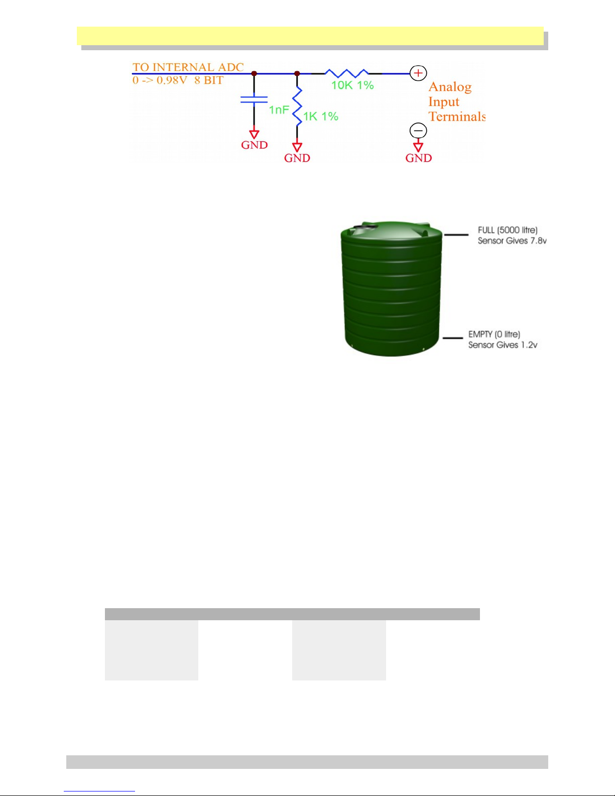
Suppose you have a water tank, with a level sensor
that is connected to the analog input of the GSM
Commander. The sensor is such, that when the tank is
empty, the voltage is 1.2V, and when the tank is full,
the voltage is 7.8V. The configuration software allows
you to request the current reading in a scaled format.
You would thus tell the software that 7.8V should correspond to 5000 litres, and 1.2V should
correspond to 0 litres, and leave the rest of the calculations to the GSM Commander.
You can now receive a message from the GSM Commander, detailing the actual contents of the tank
in litres, instead of just a raw value. (Which you would otherwise have had to convert back to
“real” numbers yourself).
Please note: This feature assumes a linear relationship between the input voltage and the desired
output units. Thus, this will not work very well for a cylindrical tank that is mounted on its side,
as the voltage from the level sensor is not linearly proportional to the actual contents of the tank.
The user is also able to define the message to precede, and the message to follow the analog value.
The output of the circuit above feeds to an Analog-to-Digital converter with a reference voltage of
0.98V, and a resolution of 8 bits. The full-scale input voltage to the GSM Commander is therefore
10.8V. The range of the analog input can easily be increased by the addition of a resistor in series
with the analog input.
Below are some examples of resistor values, and the resultant input ranges.
RESISTOR MAX VOLTAGE RESISTOR MAX VOLTAGE
1K Ohm 0 – 11.8V 18K Ohm 0 – 28.4V
3.3K Ohm 0 - 14.0V 22K Ohm 0 – 32.3V
6.8K Ohm 0 – 17.4V 39K Ohm 0 – 49.0V
10K Ohm 0 – 20.6V 56K Ohm 0 – 65.6V
15K Ohm 0 – 25.5V 68K Ohm 0 – 77.4V
The configuration software assumes no series input resistor, when defining behaviour statements for
the analog input.
© Polygon Technologies. All rights reserved Page 15

The software shows both a voltage and a “counts” value when selecting trip points for the analog
input. The “counts” value is a variable from zero to 255 (8 bits). If you have connected a 3.3K Ohm
resistor in series, and you want to select a trip point at, say 12V, you will ignore the voltage shown
by the configuration software, and simply select the correct counts value of 214. ((12 / 14) x 250*)
Please note: The analog input counts never go above 250 (This is a known hardware limitation
problem) and the input is NOT isolated, and must be used with care.
5.12. Battery Input
The GSM Commander provides connections for an external rechargeable 12V battery. Under normal
circumstances, the GSM Commander will trickle-charge the battery at a current of about 60mA. In
the case of a power failure, the GSM Commander then starts drawing power from the battery to
continue operating.
In the case of a power failure, the GSM Commander can continue operating from the external
battery. The unit can be configured to perform certain tasks (like sending a warning SMS) if the
battery voltage falls below a certain point, and can also perform tasks in the case of a power
failure. (Like sending an SMS and switching on emergency lighting)
In cases where the GSM Commander is used in conjunction with a large system with its own battery
(such as UPS systems), the battery terminals of the GSM Commander can be safely connected to the
large (12V) battery, and the GSM Commander can then monitor the battery voltage for you (only
while power is NOT supplied to the power input connector).
Also, in cases where the user may want to connect other hardware directly to the battery, be aware
that this will probably drain the battery, since the charging current from the GSM Commander is so
low. Other hardware should rather be connected to the power terminals provided at the inputs
(See sec 5.8 for more information on this).
Internal to the GSM Commander, the Battery terminal is wired with a 47ohm resistor between the +
Batt terminal and the positive power supplied to the GSM Commander. There is a diode in parallel
with this resistor (cathode facing to the battery) to allow the GSM Commander to draw power from
the battery under power-fail conditions.
A resettable fuse has now also been added to give the Battery terminal added protection against
voltage spikes and short circuits.
Suitable batteries are available from Polygon Technologies.
5.13. Internal Battery
GSM Commanders with a "+" at the end of their part numbers (GCXXXX+), are equipped with an
internal 3.7V li-ion battery. This battery can keep the unit going even when the mains power is
turned off.
Please Note: Because of the low battery voltage, the GSM Commander will not be fully functional
when running from the internal battery. Specifically, ALL INPUTS and OUTPUTS will be disabled.
The GSM Commander will still be able send/receive SMSes and voice calls. This is very handy for
applications where the only requirement of a battery is for power failure notifications. Mounting an
external lead-acid battery can be troublesome. This option will effectively solve the problem.
Another area where this feature is important, is in security applications. Sometimes criminals would
break open the enclosure and cut all the wires in an effort to prevent an SMS or call from being
made. The internal battery will be impossible to turn off, and thus they cannot prevent the
transmission.
© Polygon Technologies. All rights reserved Page 16

5.13.1. Resetting the GSM Commander (GCXXXX+)
The GSM Commander will leave the factory in a constant reset state.
The moment an external power supply is connected to the GSM Commander, the internal battery will
switch on.
Now that it is almost impossible to turn the GSM Commander off, it may be a problem to reset it. To
reset the GSM Commander, the "Turn-Off " dongle that is supplied with the unit must be inserted into
the GSM Commander's RS232 port. This will place the GSM Commander in in a constant reset state.
Removing it will return the GSM Commander to normal functionality.
5.13.2. Pitfalls
It is NOT recommended to remove or insert the SIM card while the GSM Commander is powered up,
thus we advise that the GSM Commander should first be in the reset state (See sec 5.4) before
removing or inserting the SIM card.
5.14. Expansion Unit
The GSM Commander supports comprehensive expansion by means of the GSM Commander Expansion
unit, which provides an additional 5 inputs and 5 outputs similar to the ones found on the GSM
Commander itself. A total of 6 Expansion units may be daisy chained to provide a maximum of 30
outputs and 30 inputs* in addition to those on the GSM Commander itself.
14V DC Jack and Battery Input on Expansion Unit
Each Expansion unit has both a 14V DC jack and battery input, so that it could also be powered by a
separate power supply and battery. Applying power to the Expansion unit either through the DC jack
or battery terminal is optional. The Expansion unit can draw power via the ribbon cable, but under
certain conditions it is better to supply a separate 14V source and battery to the expansion unit.
These conditions are:
➢ When the ribbon cable run becomes very long (>5m)
➢ If you are going to connect more than one expansion unit
➢ If you expect to draw power from the input on the Expansion unit
➢ If you expect most of the inputs and outputs on the expansion to likely be active at once
© Polygon Technologies. All rights reserved Page 17
The Expansion unit will automatically detect if power is applied at either of the it's 14V inputs (DC
jack and battery) and thus stop drawing power via the ribbon cable. So to ensure that the Expansion
unit functions properly in mains power failure conditions, it is advised that you connect a 12V
battery to it's battery terminals together with it's main 14V power supply.
Interface Ribbon cable
Supplied with each Expansion unit is a short (40cm) ribbon cable for interface purposes, but this
ribbon can also be very long. We have tested up to 10m, but we generally recommend a maximum
cable run of 7-8m. Please contact us if you need a longer ribbon cable.
The ribbon cable connectors are mounted such that pin 1 on the one end connects to pin 10 on the
other, Pin 2 connects to pin 9 etc.
It is important to connect the Expansion port on the GSM Commander to the IN connection on the
expansion unit. An additional Expansion unit must be connected with its IN connection to the OUT
connection of the “upstream” Expansion unit.
* Model Dependent (See Feature Matrix in Section 2)
5.15. Dimensions of Expansion Unit
© Polygon Technologies. All rights reserved Page 18

5.16. Status LEDs
The GSM Commander has 2 LEDs to show the current status of the GSM Commander. The red LED,
labelled “GSM”, shows the status of the internal GSM cellular engine, while the green LED, labelled
“STATUS”, shows the status of the GSM Commander as a whole.
The following table shows how one can determine the current status:
GREEN LED (STATUS)
➢ Solid On
: Busy Booting
➢ on for 500ms, off for 500ms (slow flash)
: All OK
➢ on for 200ms, off for 200ms (fast flash)
: Airtime running low
➢ on for 10ms, off for 500ms (2 short flashes per second)
: Signal is low
➢ on for 50ms, off for 50ms (very fast flash)
: Problem with GSM engine
➢ on for 100ms, off for 500ms, on for 100ms, off for 500ms,
on for 500ms, off for 500ms (2 short and 1 long flash)
: Setup is corrupt
➢ on for 50ms, off for 100ms, on for 50ms, off for 100ms,
on for 50ms, off for 1000ms (3 short flashes)
: Supply voltage below 9,5V
RED LED (GSM)
Applicable to units with SN:xxxxxx- 3 xxxx:
➢ OFF : GSM engine OFF
➢ on for 600ms, off for 600ms
: GSM engine searching for network
➢ on for 75ms, off for 3000ms (1 short flash every 3 seconds)
: GSM engine registered OK
➢ Solid On
: GSM busy with a voice-call
© Polygon Technologies. All rights reserved Page 19

Applicable to units with SN:xxxxxx- 4 xxxx:
➢ OFF : GSM engine OFF
➢ on for 64ms, off for 800ms
: GSM engine searching for network
➢ on for 64ms, off for 2000ms (1 short flash every 2 seconds)
: GSM engine registered OK
Applicable to units with SN:xxxxxx- 5 xxxx:
➢ OFF : GSM engine OFF
➢ on for 200ms, off for 1800ms
: GSM engine searching for network
➢ on for 1800ms, off for 200ms
: GSM engine registered OK
➢ Solid On
: GSM busy with a voice-call
© Polygon Technologies. All rights reserved Page 20

5.17. Testing the GSM Commander
5.17.1. Status Request
The GSM Commander (even with a blank configuration) has a built-in test feature. If the GSM
Commander receives “TEST GSMC” as an SMS message, it will reply to the number that sent the
message, with the following text:
DT=01/01/2017-12:00:00 < Indicates current date & time of the GSM Commander
Sig=68% < Indicates the received signal strength
AT=35 < Indicates the amount of airtime remaining
FW=7.46 < Indicates the firmware version
SN=160641-30001 < Indicates the serial number
PWR=On < Indicates status of mains power
BT=13.2V < Indicates voltage of battery (if connected)
A=108 < Indicates analog value in counts (0 - 250)
T= 23,18 < 1st value indicates temperature of Probe A (in °C) if connected and
2
nd
value indicates temperature of Probe B (in °C) if connected
IN1,2=0,1 < Indicates status of inputs 1 and 2 (0 = inactive, 1 = active)
OUT1,2=0,1 < Indicates status of outputs1 and 2 (0 = inactive, 1 = active)
SIM=1 < Indicates active SIM card *
Please Note: The airtime remaining will be displayed as “AT=--” if airtime checking has been
disabled or the incorrect network operator has been chosen in the current setup.
* Only applicable to the GC1281 model
© Polygon Technologies. All rights reserved Page 21

5.18. Commissioning Mode
This function was introduced in version 7.46 of the the SmartSetup software. Commissioning Mode is
basically a TESTING mode without needing physical triggers. This is ideal for workshop testing,
before going live.
Examples what you can do:
1. Trigger inputs without physically triggering it. Just click on the input number in the status.
Clicking it will toggle the input state.
2. Change Variable values. Just left click on the variable and a box will pop up where you can
change the variable value.
3. Test / simulate global details. This includes Power ON / OFF, Battery value, Temp on probe A
& B, Analog value.
You can simulate / change the following values:
• Power status ( 1 – ON / 0 – OFF)
• Battery voltage
• Analog value
• Temperatures (probe A & B)
• Date / time
© Polygon Technologies. All rights reserved Page 22

6. CONFIGURATION VIA PC
6.1. Basics
The following is required to configure the GSM Commander:
➢ A PC running Windows XP / Vista / Windows 7 / Windows 8/ Windows 10
➢ Setup utility installed on the PC (Available on the CD supplied with the product)
or downloaded at https://gsmcommander.com/downloads/software
➢ USB cable
➢ Power supply (See sec 6.2)
➢ Antenna (See sec 6.5)
➢ SIM card(s) (See sec 6.4)
Please note: The GSM Commander will eventually startup if no SIM card is inserted, but there
would be no GSM functionality, which means none of the GSM features will work.
Follow these steps:
Step 1:
Insert SIM card(s) into unit (when unit is not powered up)
Step 2:
Connect GSM Commander to PC via the supplied USB cable
Step 3:
Connect power to the GSM Commander
Step 4:
Run the Utility
Start Menu> All Programs [All Apps] >GSM Commander V7 > Configure GSM Commander)
The software will show this screen when
started. Here you can select whether you
would prefer opening an existing setup
from a file on your PC, retrieve the setup
currently on the GSM Commander, just
open to the main screen.
© Polygon Technologies. All rights reserved Page 23
6.2. Software Tabs
The GSM Commander Setup Utility software has been designed to make the configuration process of
the GSM Commander as easy and user-friendly as possibly. With this in mind the software has been
divided into the following tabs:
➢ Numbers
➢ Messages
➢ Behaviour Statements
➢ Settings
➢ Status
➢ IO Names
➢ Analog Scaling (For Analog expansion only – in conjunction with GC-0641 or GC-1281)
➢ Lock Setup
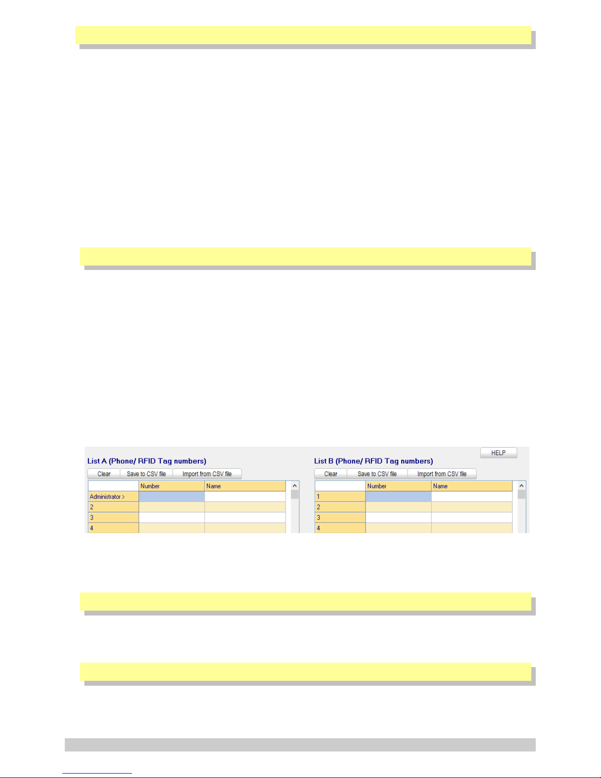
6.2.1. Numbers Tab List A and B
This tab allows the user to program the GSM Commander with the numbers they wish the GSM
Commander to communicate with and listen to. There is a list A and list B which allows one to save
phone numbers and RFID tag numbers to the device for further functionality.
RFID tag numbers will be used when the GSM Commander is fitted with the Stealth RFID Reader
125KHz antenna (Product Code: GA100).
List A and List B provides the option to easily prioritize certain users according to the 2 groups.
ie. special ability could be granted to numbers in list A and restricted ability could be
granted to those in list B.
The FIRST number in the list A is defined as the ADMINISTRATOR number. Only the Administrator
may send configuration SMS messages to the device. (See sec 7 for more information)
Please Note: The user should adjust the sliding bar at the bottom of the screen to reserve space
for numbers to be added/removed via SMS. The numbers added/removed via sms will affect the
list B only not list A. So one cannot add or remove numbers from list A but only list B.
6.2.2. Messages Tab
This tab allows the user to program the GSM Commander with the messages they wish the GSM
Commander to respond to and respond with.
6.2.3. Behaviour Statements Tab
This tab allows the user to program the GSM Commander with a number of trigger conditions.
(See sec 8)
© Polygon Technologies. All rights reserved Page 24

6.2.4. Settings Tab
This tab allows the user to configure the following:
➢ Network Service and GPRS Settings
➢ Temperature Probe Configuration
➢ Enable/Disable SIM card Pin(s)
➢ Enable/Disable Periodic Automatic GSM Reset
➢ Set Default Baud-rate
➢ Show Debug Comms
➢ Manually send an SMS via the GSM Commander
➢ Write Recipient and IO Names to device
➢ Enable/disable settime messages
➢ Enable/disable inhibit if supply voltage not good
➢ Assign on-board analog input to Variable P*
➢ Assign on-board temp inputs to Variable N and O*
➢ Only use control channel for sms delivery
➢ Recall Device Status on startup
➢ Asset ID String
➢ My number
➢ Special settings
6.2.5. Status Tab
This tab allows the user to monitor the status of GSM Commander (while connected to PC) with
regards to:
➢ Active SIM
➢ GSM Status
➢ GPRS Status
➢ Power Status
➢ Temperature Status
➢ Current Battery Voltage (combination of battery & power supply voltage)
➢ Current Analog Value
➢ Signal Strength
➢ Airtime Balance Available (provided network settings are correct in settings tab of the software)
➢ Date / Time
➢ Status of Behaviour Statements
➢ Status of Variables*
➢ Inputs/Outputs Status
➢ Stuff happening right now
* Only applicable to the GC-0641 & GC-1281 models
© Polygon Technologies. All rights reserved Page 25

6.2.6. IO Names Tab
This tab allows the user to rename the inputs and outputs to something that means a little more.
Please Note: These IO Name changes will be stored in the setup that is saved to file, but will
ONLY be stored in the setup that is saved to the GSM Commander if enabled under Settings Tab.
6.2.7. Analog Scaling Tab
This tab allows the user enable the Analog scaling functionality when an Analog Expansion Unit is
connected to the GSM Commander. (See sec 12)
6.2.8. Lock Setup
This tab allows the user to password protect tabs from being accessed as well as the option to save
a new setup to the GSM Commander. This feature comes in handy when an installer doesn't want
the end-user to be able to make changes under certain tabs.
© Polygon Technologies. All rights reserved Page 26

7. CONFIGURATION VIA SMS
The GSM commander provides functionality to provide some configuration changes to be done via
SMS message (from the administrator number only). Note that the unit cannot be setup by SMS only.
A PC is still required to perform the initial setup. Thereafter, some simple changes to the setup may
be done using SMS messages.
Please note: The Configuration SMS is NOT case sensitive.
The following operations can be performed via SMS message:
➢ Set Administrator number
➢ Clear Administrator number
➢ Check Administrator number
➢ Check Airtime
➢ Add a number to the list
➢ Remove a number from the list
➢ Enable/Disable statements
➢ Configure GPRS settings
➢ Reset GPRS
➢ Set GPRS logging interval
➢ Switch SIM card
➢ Reset GSM Commander
7.1. Set Administrator number
This command can ONLY be sent from the administrator number(if one exists), otherwise it can be
sent from any number .
ADMIN SETADM 0831234567
This will store “0831234567” as the new administrator number. The GSM Commander will reply with
a confirmation message.
7.2. Clear Administrator number
This command can ONLY be sent from the administrator number.
ADMIN CLRADM
This will remove the current administrator number. The GSM Commander will reply with a
confirmation message.
© Polygon Technologies. All rights reserved Page 27

7.3. Check Administrator number
This command can be sent from ANY number, and is useful to determine which number is the correct
administrator number.
ADMIN?
The GSM Commander will reply with the administrator number in the reply message.
7.4. Check Airtime
This command can be sent from ANY number, and is useful to check the amount of airtime remaining
on the unit. To check airtime, you must send:
ATCHECK
The GSM Commander will reply with a message detailing the current airtime.
7.5. Add a Number to the list
This command can only be sent from the administrator number. To add a number to the list, the
administrator must send:
ADMIN ADDN 0831234567
The GSM Commander will reply with a confirmation message.
7.6. Remove a Number from the list
This command can only be sent from the administrator number. To remove a number
(+27831234567) from the list, the administrator must send:
ADMIN REMN 0831234567
The GSM Commander will reply with a confirmation message.
Please Note: The value predefined by the user via the software under the “Numbers Tab” (as
illustrated below), will determine how many numbers are able to be added and removed by means
of SMS.
7.7. Enable/Disable statements
This command can only be sent from the administrator number. To enable or disable a specific
statement in the setup on the GSM Commander, the administrator must send:
ADMIN STATEMENT 8 ON or ADMIN STATEMENT 8 OFF
This will either enable(ON) or disable(OFF) statement 8 respectively. The GSM Commander will reply
with a confirmation message.
© Polygon Technologies. All rights reserved Page 28

7.8. Override GPRS Settings
This set of commands allows you to override the GPRS settings that the GSM Commander may have
been configured with and can only be sent from the administrator number. These override settings
are volatile, which means their effect will not be retained after power has been recycled.
To configure the GSM Commander to connect to the Airdrive 7.2 server via a South African network
you must send:
ADMIN SETSERVER: "internet" "" "" "UCGPBUPGGQGC"
(applicable to firmware version 7.3x and earlier)
OR
ADMIN GPRSSETUP.AIRDRIVE
(applicable from firmware version 7.42 onwards)
To turn off GPRS functionality you must send:
ADMIN GPRSSETUP.OFF
To disable any override, and go back to whatever settings were specified by the configuration, you
must send:
ADMIN GPRSSETUP.SETUP
If you need to specify the username and password of your APN(Access Point Name) you must send:
ADMIN SETSERVER: "<apn>" "<username>" "<password>" "UCGPBUPGGQGC"
The GSM Commander will reply with a confirmation message for each of the above.
7.9. Reset GPRS
This command can only be sent from the administrator number. To re-open GPRS you must send:
RESET GPRS
The GSM Commander will reply with a confirmation message.
7.10. Set GPRS logging interval
This set of commands allows you to override the GPRS logging interval that the GSM Commander may
have been configured with and can only be sent from the administrator number. These override
settings are non-volatile, which means their effect will remain after power has been cycled.
ADMIN GPRSSETUP.LOG5
(GPRS logging interval will be set to every 5 minutes)
ADMIN GPRSSETUP.LOG30
(GPRS logging interval will be set to every 30 minutes)
The GSM Commander will reply with a confirmation message.
© Polygon Technologies. All rights reserved Page 29

7.11. IMEI Number
If you need the IMEI number of the device, you can send the following command from the
Administrator's phone / number. It will reply via SMS with the IMEI number. This is very useful if you
need the IMEI number for our online, Airdrive platform, to add a new unit, for example.
ADMIN IMEI
Please note: This function only works with firmware versions 7.43 and above
The only other way to retrieve the IMEI number is, when you have the unit connected via USB in the
SmartSetup software and get it from the STATUS tab.
7.12. Switch SIM card
This set of commands allows you switch from the one SIM card to the other and can only be sent
from the administrator number on a GC-1281 unit only.
To switch to primary SIM card you must send:
SIM1
To switch to secondary SIM card you must send:
SIM2
To switch from the currently active SIM card to the inactive SIM card you must send:
SIMTOGGLE
7.13. Reset GSM Commander
This command can be sent from ANY number. To reset the GSM Commander you must send:
RESET GSMC
© Polygon Technologies. All rights reserved Page 30

8. IF-THEN BEHAVIOUR STATEMENTS
The GSM Commander is configured by defining a number of behaviour statements. Each statement
takes the form of an IF-THEN pair. You are thus able to select certain trigger conditions that will
cause desired actions to be performed. Any combination of IF and THEN parts can be assembled into
complete statements using the configuration software. The GSM Commander can accept up to 128
separate behaviour statements, depending on the model .
One is also able to select time and input/output* constraints for any IF-THEN statement pair, so that
a statement will only be allowed to trigger at certain times of day, and on certain days of the week
or only if certain input/output conditions are met.
8.1. Supported IF Conditions
8.1.1. IF a Message is Received
A statement containing this IF condition, will trigger on the arrival of a SMS message.
The user has a choice of the following seven options:
• From Any number Containing Anything or a Specific Message
• From Any number appearing in the list A Containing Anything or a Specific Message
• From Any number appearing in the list B Containing Anything or a Specific Message
• From Any number appearing in the list A or B Containing Anything or a Specific Message
• From one Specific number in the list A Containing Anything or a Specific Message
• From Any un-listed number Containing Anything or a Specific Message
• From Serial port Containing a Specific Message (“Serial Port” refers to the connection labelled “RS232”)
Thus, if the user chooses “From Any number Containing Anything or a Specific Message”, then literally any
SMS(if not specified) from any number will cause the statement to trigger. This will include SMS messages
from private (withheld) numbers.
Note the word “containing” in this condition. If you have a trigger condition like this one:
IF a Message is Received From Any number containing “Apple” is received from XYZ, then <ACTION>,
The statement will trigger on arrival of any of the following messages:
“Apple”
“APPLE”
“The Red apple”
You will notice that trigger text strings are NOT case sensitive. Both “Apple” and “APPLE” will work fine.
It is also important to note that you can trigger multiple statements with different trigger texts, in the
same SMS. For example, if you have the following two statements:
IF a Message is Received From Any number containing “Apple” is received from XYZ, then <ACTION>
IF a Message is Received From Any number containing “eat” is received from XYZ, then <ACTION>
These statements will both be triggered if “I eat an Apple” is received via SMS.
Please Note: If “From Any number appearing in the list Containing Anything or a Specific Message” or
“From a Specific number in the list Containing Anything or a Specific Message” are selected, and an SMS
arrives from a private number, the statement will not trigger.
If the user chooses “From Serial port Containing a Specific Message”, then a specific message sent via a PC
through a Serial connection(See section 15) to the unit will cause the statement to trigger.
© Polygon Technologies. All rights reserved Page 31

8.1.2. IF Voice Call is Received (Call Options : Hang up or Stay on)
A statement containing this IF condition, will trigger if someone actually places a call to the GSM
Commander number. The user has the option to select which group of senders (originators) are able to
cause the the statement to trigger.
The user can choose between the following six options:
• From Any number
• From Any number in list A
• From Any number in list B
• From Any number in list A or B
• From one specific number in list A
• Any un-listed number
Thus, if the user chooses “From any number”, then literally any call from any number will cause the
statement to trigger (This will include calls from private numbers). The same applies to the remaining
options, provided their conditions are met.
Please Note: If anyone of the other two options are selected, and a voice call is made from a private
number, the statement will not trigger.
As soon as the statement triggers, the GSM Commander will hang up (if option is selected). This is of
importance, because it allows the user to have some sort of feedback that the GSM Commander has in fact
responded to the call.
Since the GSM Commander answers the call for a split second, it is cost effective. This type of statement
option is very handy to use for tasks of high importance, for instance the arming of an alarm system.
If the “Stay on” call option is selected, the GSM Commander will hold the call until the caller ends the
call.
Please Note: If the “Stay On” call option is selected it should be defined in the last “IF Voice Call is
Received” behaviour statement (if any exist).
8.1.3. IF Input
A statement containing this IF condition, will trigger if the selected input changes according to
specification.
The user can choose between the following seven options.
• Goes Active (Trigger on rising edge)
• Goes Inactive (Trigger on falling edge)
• Changes State (Trigger on rising or falling edge)
• Goes Active, remaining Active for longer than
• Goes Inactive, remaining Inactive for longer than
• Is Active (Trigger on high level)
• Is Inactive (Trigger on low level)
Thus, if the user chooses “Goes Active”, then as soon as the specified input changes from inactive to
active, the statement will trigger. The same applies to the remaining options, provided their conditions
are met.
The user is also able to specify a “Lockout Time” for this statement, which is the time that, after the
statement has triggered, it will not allowed to trigger again until this time has elapsed.
If the user selects a “Lockout Time” of zero, the statement will only trigger once (will trigger again when
the trigger condition has changed and becomes true again, with the last two options being an exception).
© Polygon Technologies. All rights reserved Page 32

8.1.4. IF Output
This trigger condition is very similar to “IF Input”, as it monitors and output instead of an input.
8.1.5. IF Logic Expression
A statement containing this IF condition, will trigger if the specified logic conditions are met. This allows
the user to specify interesting combinations, like input 1 AND input 2 must be active before action is
taken.
The user is also able to specify a “Lockout Time” for this statement, which is the time that, after the
statement has triggered, it will not allowed to trigger again until this time has elapsed.
The logic options available includes:
AND : ALL the selected signals become active (TRUE) or ANY of the selected signals become inactive (FALSE)
OR : ANY of the selected signals become active (TRUE) or ALL of the selected signals become inactive (FALSE)
XOR : ANY UNEVEN number of the selected signals become active (TRUE) or ANY EVEN number of the selected
signals become active (FALSE)
8.1.6. IF Variable*
A statement containing this IF condition, will trigger if selected variable meets the specified
requirements.
The user can choose between the following two options:
• Check if Above Threshold
• Check if Below Threshold
Thus, if the user chooses “Check if Above Threshold”, then as soon as the specified variable goes above
the specified threshold, the statement will trigger. The same applies to the other option, provided it's
condition is met.
The user is also able to specify a “Hold Time” for this statement, which is the time that the trigger
condition must continuously be true before it will be allowed to trigger
The user is also able to specify a “Lockout Time” for this statement, which is the time that, after the
statement has triggered, it will not allowed to trigger again until this time has elapsed.
If the user selects a “Lockout Time” of zero, the statement will only trigger once (will trigger again when
the trigger condition has changed and becomes true again).
8.1.7. IF DTMF Tone is Received During Voice Call*
A statement containing this IF condition, will trigger as soon as the selected digit tone is detected during
an ongoing voice call. Obviously, for this to work, you need to have another statement that will answer
and keep the call open, typically something of the form "IF Voice Call is Received from ABC, then do
nothing" - at the setup of this statement is a check-box where you can select to keep the incoming call
open.
Please Note : If the “Stay On” call option is selected it should be defined in the last “IF Voice Call is
Received” behaviour statement (if any exist).
To note: The 3G enabled models do not have DTMF functionality, as there is no analog capabilities on the
GSM module.
* Only available on the 0641 and 1281 models
© Polygon Technologies. All rights reserved Page 33

8.1.8. IF Analog Input
A statement containing this IF condition, will trigger if the analog voltage measured at the terminals
meets the specified requirements.
The user can choose between the following four options:
• Check if Above Threshold
• Check if Below Threshold
• Check if Inside Window
• Check if Outside Window
Thus, if the user chooses “Check if Above Threshold”, then as soon as the analog voltage measured at the
terminals goes above the specified threshold, the statement will trigger. The same applies to the
remaining options, provided their conditions are met.
The user is also able to specify a “Hold Time” for this statement, which is the time that the trigger
condition must continuously be true before it will be allowed to trigger.
The user is able to specify a “Lockout Time” for this statement, which is the time that, after the
statement has triggered, it will not allowed to trigger again until this time has elapsed.
In other words, if you select a “Lockout Time” of 10 minutes, a “Hold Time” of 5 seconds, and choose
“Check if Above Threshold” of 5V, the statement will trigger as soon as the voltage goes above 5V, and
remains above 5V for 5 seconds. It will then start checking the input again after 10 minutes and trigger
once more if the voltage is above 5V for 5 seconds.
If the user selects a “Lockout Time” of zero, the statement will only trigger once (will trigger again when
the trigger condition has changed and becomes true again).
8.1.9. IF Temperature
A statement containing this IF condition, will trigger if the temperature measured at the probe meets the
specified requirements.
The user can choose between the following four options:
• Check if Above Threshold / Check if Below Threshold
• Check if Inside Window / Check if Outside Window
Thus, if the user chooses “Check if Above Threshold”, then as soon as the temperature measured at the
probe goes above the specified threshold, the statement will trigger. The same applies to the remaining
options, provided their conditions are met.
The user is able to specify a “Lockout Time” for this statement, which is the time that, after the
statement has triggered, it will not allowed to trigger again until this time has elapsed.
The user is also able to specify a “Hold Time” for this statement, which is the time that the trigger
condition must continuously be true before it will be allowed to trigger.
In other words, if you select a “Lockout Time” of 10 minutes, a “Hold Time” of 5 seconds, and choose
“Check if Above Threshold” of 30°C, the statement will trigger as soon as the temperature goes above
30°C, and remains above 30°C for 5 seconds. It will then start checking the temperature again after 10
minutes and trigger once more if the temperature is above 30°C for 5 seconds.
If the user selects a “Lockout Time” of zero, the statement will only trigger once (will trigger again when
the trigger condition has changed and becomes true again).
Please Note: To use this option, you need to have a temperature probe connected to the expansion port
of the GSM Commander via a temperature interface module. Also make sure that the correct type of
probe is selected in the “Temperature Probe Configuration” box under the “Settings” tab in the
software.
© Polygon Technologies. All rights reserved Page 34

8.1.10. IF Power Failure Detected
A statement containing this IF condition, will trigger if the power supplies to the 2.1mm DC jack power
connector on the GSM Commander is interrupted.
The user is able to specify a “Lockout Time” for this statement, which is the time that, after the
statement has triggered, it will not allowed to trigger again until this time has elapsed.
The user is also able to specify a “Hold Time” for this statement, which is the time that the trigger
condition must continuously be true before it will be allowed to trigger.
If the user selects a “Lockout Time” of zero, the statement will only trigger once (will trigger again when
the power is restored and fails again).
Please Note: To use this option, the user needs to have a 12V battery connected to the BATT terminals on
the GSM Commander or an internal battery (see 6.13). The GSM commander will operate from the
battery in the case of a power failure.
8.1.11. IF Power Restored
This trigger condition is the inverse of 15.1.9.
8.1.12. IF Battery Voltage < X
A statement containing this IF condition, will trigger if the battery voltage goes below a preset threshold
level.
The user is also able to specify a “Hold Time” for this statement, which is the time that the trigger
condition must continuously be true before it will be allowed to trigger.
The user is able to specify a “Lockout Time” for this statement, which is the time that, after the
statement has triggered, it will not allowed to trigger again until this time has elapsed.
If the user selects a “Lockout Time” of zero, the statement will only trigger once (will trigger again when
the voltage goes above and below “X”).
Please Note: To use this option, the user needs to have a 12V battery connected to the BATT terminals on
the GSM Commander.
The GSM commander will operate from the battery in the case of a power failure. While the GSM
Commander is powered, the battery will be trickle-charged by the GSM Commander. It is therefore
important to note that the battery level will only be checked while a power-failure is in progress.
8.1.13. IF Prepaid Airtime < X
A statement containing this IF condition, will trigger if the prepaid airtime goes below a preset threshold
level.
The user is able to specify a “Lockout Time” for this statement, which is the time that, after the
statement has triggered, it will not allowed to trigger again until this time has elapsed.
The GSM Commander will check the prepaid airtime balance from time to time, and the statement will
trigger if the balance is below the selected threshold.
Please Note: To use this option, the user obviously needs to use a PREPAID SIM card.
Important: Under the “Settings” Tab in the configuration software, you need to have “DO NOT Check
Airtime” unchecked, which is found in “Edit Settings”. Also make sure that the correct network is
selected.
© Polygon Technologies. All rights reserved Page 35

8.1.14. IF time elapsed > X
A statement containing this IF condition, will trigger every X seconds or minutes.
8.1.15. IF Statement X has not triggered in a certain period
A statement containing this IF condition, will trigger if the referred-to-statement has triggered in a
specified period. Thus this type of statement actually monitors the triggering behaviour of another
statement.
8.1.16. IF Date/Time = X
A statement containing this IF condition, will trigger on a specific time every day within a specified range
of dates, or on every selected day of the week.
The user can choose between the following four options:
1. Everyday 2. Day-of-Week 3. Once per month 4. Specific Date Range
8.1.17. IF Power-up or Reset
A statement containing this IF condition, will trigger as soon as the unit has finished booting up.
8.1.18. IF GSM Signal Strength
A statement containing this IF condition, will trigger as soon as GSM signal strength meets the specified
requirements.
The user can choose between the following two options:
• Above X
• Below X
Thus, if the user chooses “Below X”, then as soon as the GSM signal strength goes below the specified
threshold, the statement will trigger. The same applies to the remaining options, provided their conditions
are met. The same applies to the other option, provided it's condition is met.
The user is able to specify a “Lockout Time” for this statement, which is the time that, after the
statement has triggered, it will not allowed to trigger again until this time has elapsed.
If the user selects a “Lockout Time” of zero and the “Below X” option, the statement will only trigger
once (will trigger again when the signal goes above and below “X”).
8.1.19. IF Statement X Triggers
A statement containing this IF condition, will trigger if the referred-to-statement has triggered. Thus this
type of statement actually monitors the triggering behaviour of another statement.
8.1.20. IF RFID Tag is read via Serial
A statement containing this IF condition, will trigger if a RFID tag is scanned via a Stealth RFID Reader
125KHz antenna (Product Code: GA100) that is fitted to the GSM Commander.
The user can choose between the same six options as listed under “IF Voice Call is Received”
(See sec 8.1.2 for more detail)
Please note: * Only available on the 0641 and 1281 models
** Only available on the 1281 model
© Polygon Technologies. All rights reserved Page 36

8.2. Supported THEN Actions
8.2.1. THEN Change Output
A statement containing this Action, will change the selected output according to specified actions.
The user can choose between the following five actions:
• Activate for a time
• Activate for a time – Pause – Activate for a time
• Activate (Leave Activated)
• De-Activate (Leave De-Activated)
• Change State
If the user chooses:
➢ “Activate for a time”, it will Activate the selected output for the selected number of seconds specified.
➢ “Activate for a time – Pause – Activate for a time”, it will Activate the selected output for the selected
number of seconds specified. The output will remain off for a selected period, after which it will again
activate for the selected number of seconds.
➢ “Activate (Leave Activated)”, it will Activate the selected output and leave it activated. The inverse
applies to “De-Activate (Leave De-Activated)”.
➢ “Change State”, it will either change the state of the selected output, meaning that it will active it if it
was de-activated and vice versa.
8.2.2. THEN Send Message
A statement containing this Action, will send a message via SMS to each of up to 6 selected recipients or a
message via Serial port or a message to our server.
The user can choose between the following fourteen options:
• Plain Message
• Input / Output Status
• General Status
• Analog Input Status (Able to define own scale and unit)
• Global Input Status
• Global Output Status
• Please Call Me
• Baselog Message
• Log Status to Sever*
If the user chooses:
➢ “Plain Message”, it will send a predefined message either via SMS to each of up to 6 selected recipients,
via the serial port or to server*.
➢ “Input / Output Status”, it will send a predefined message(one for active and one for inactive) regarding
the status of the selected input or output either via SMS to each of up to 6 selected recipients, via the
serial port or to server*.
➢ “General Status”, it will send a general status message either via SMS to each of up to 6 selected
recipients, via the serial port or to server* containing the following information: date & time, signal
strength, firmware version, serial number, airtime remaining, status of mains power.
➢ “Analog Input Status”, it will send a message either via SMS to each of up to 6 selected recipients, via
the serial port or to server* containing the status of the analog input. The user is able to specify the
maximum and minimum value as well as the unit. The user is also able to define the message to
precede, and the message to follow the analog value.
© Polygon Technologies. All rights reserved Page 37

➢ “Global Input Status”, it will send a message either via SMS to each of up to 6 selected recipients, via
the serial port or to server* containing the status of the inputs. (only inputs 1-12 are displayed)
➢ “Global Output Status”, it will send a message either via SMS to each of up to 6 selected recipients, via
the serial port or to server* containing the status of the inputs. (only outputs 1-12 are displayed)
➢ “Please Call Me”, it will send a “Please Call Me” message via SMS to each of up to 6 selected recipients .
Please note that the “Please Call Me” will only work if the correct network is selected in the Settings
tab of the configuration software.
➢ “Baselog Message”, it will send a message either via SMS to each of up to 6 selected recipients, via the
serial port or to server* containing the information required by the GSM Base Logger software.
➢ “Log Status to Server”, it will send a status message via GPRS to our server to update the status of the
GSM Commander on the AirDrive platform. (Log onto Airdrive to find out more)
The recipient number can be defined in one of the following six ways:
• Not Used
• Last voice call number
• Last SMS number
• Reply to originating number (only available with IF conditions 8.1.1 and 8.1.2)
• a predefined number from the “numbers” list A or B
• a new number
The user also has the option to insert special characters into the string to create more complex messages.
(See section 10) See section 15 to find out more about the serial port.
8.2.3. THEN Place Voice Call
A statement containing this Action, will place a voice call to each of up to 6 selected recipients. The user
is able to specify the time to ring, the number of calls to make as well as the time between calls.
The recipient number can be defined in one of the following five ways:
• Not Used
• Last voice call number
• Last SMS number
• A predefined number from the “numbers” list
• A new number
Please Note: If a call is answered, then hung up, subsequent calls for this event will be cancelled.
8.2.4. THEN Enable/Disable Statements
A statement containing this Action, will enable or disable up to a maximum of 8 selected behaviour
statements such that it will be allowed to trigger if it is enabled and not be allowed to trigger if it is
disabled.
8.2.5. THEN Enable/Disable ALL SMS Sending
A statement containing this Action, will enable or disable ALL SMSes, meaning that if it is enabled it will
allow the sending of any SMS messages and if it is disabled it will inhibit the sending of any SMS messages.
8.2.6. THEN Set Multiple Outputs to Pattern
A statement containing this Action, will change the status of multiple outputs to a certain state.
© Polygon Technologies. All rights reserved Page 38

8.2.7. THEN Change Variable*
A statement containing this Action, will change the selected variable according to specified actions. The
user can choose between the following five actions:
• Increment variable
• Decrement variable
• Clear variable
• Set variable to a specific value
8.2.8. THEN Change Active SIM Card**
A statement containing this Action, will change to the selected SIM card or toggle the active SIM Card.
8.2.9. THEN Copy Variable*
A statement containing this Action, will copy a selected variable to another variable.
8.2.10. THEN Perform Math Operation*
A statement containing this Action, will allow the GSM Commander to perform some basic math operations
on the variables.
8.2.11. Save Device Status
A statement containing this Action, will save all current statuses to memory, including all variable values
& current status of outputs. If the Recall Device Status on startup (See sec 6.2.4) is enabled, it will
recall the latest saved status when the unit initiates a restart.
Please note: If an output is temporarily activated by your setup, and the reset occurs during the the
time it happens to be active, the output will be re-activated on startup, but will remain active.
8.2.12. THEN Reset device
A statement containing this Action, will reset the GSM Commander.
Please note: * Only available on the 0641 and 1281 models
** Only available on the 1281 model
9. MULTIPLE ACTIONS TO A SINGLE IF CONDITION
It is often required to have more than a single action to be executed for a single trigger condition.
For instance, if your home alarm is triggered, you may want to activate an output (that in turns
switches on a loud alarm or perhaps pulls the trigger on a rigged-up shotgun), and you also want to
receive a voice-call and an SMS as well.
The GSM Commander will always execute all statements that are eligible to trigger due to a certain
event, in other words, the first statement that is triggered, does not void or “eat up” the event.
So to take our example, we will have a set of statements like:
Statement 1: IF input 1 becomes Active, THEN Place Voice Call to <your number>
Statement 2: IF input 1 becomes Active, THEN Send XYZ via SMS to <your number>
Statement 3: IF input 1 becomes Active, THEN Activate Output 1 for 10 minutes
If input 1 becomes active, all the above statements will trigger, and their associated actions will
take place (The action for the first statement will be executed first). Alternatively, “IF Statement X
Triggers” could have been used. (See sec 8.1.19)
© Polygon Technologies. All rights reserved Page 39

10. MESSAGE PARAMETERS
The GSM Commander support the use of parameters in predefined messages. This allows the user to
insert and refer to certain values in message.
➢ \t – Current time (HH:MM:SS)
➢ \d – Current date (DD/MM/YYYY)
➢ \a – Current analog input reading (0-255)
➢ \# – Unit's serial number
➢ \f – Unit's current firmware version
➢ \b – Battery voltage (in volts)
➢ \p – Current power status of mains
➢ \1 – Temperature probe A reading (in °C)
➢ \2 – Temperature probe B reading (in °C)
➢ \s – GSM signal strength (in %)
➢ \c – Airtime credit remaining (local currency)
➢ \i– Current status of inputs (32-bit hexadecimal bitmap)
➢ \o – Current status of outputs (32-bit hexadecimal bitmap)
➢ \v – Last received voice call number
➢ \w – Last received voice call name
➢ \m – Last received message number
➢ \y- Last received message name
➢ \q – Last received message text
➢ \@ - Last scanned RFID tag
➢ \! - Last scanned RFID tag name
➢ \r – Carriage Return (0x0D)
➢ \n – Line Feed (0x0A)
➢ \$ - Asset ID
➢ \+ - Own number
➢ \A – Variable A
➢ \B – Variable B
➢ \C – Variable C
➢ \D – Variable D
➢ \E – Variable E
➢ \F– Variable F
➢ \G– Variable G
➢ \H – Variable H
➢ \I – Variable I
➢ \J – Variable J
➢ \K – Variable K
➢ \L– Variable L
➢ \M – Variable M
➢ \N – Variable N
➢ \O – Variable O
➢ \P – Variable P
For example:
“Serial no \#'s signal is \s%” will send “Serial no 100641-12345's signal is 75%”
For Variables A..P, it is also possible to specify a decimal point. You do this by adding a number (1,2
or 3) after the parameter, and this number will indicate the position of the decimal point. \A1 will
show digit after the decimal, \A2 will show 2 digits etc. Let us assume Var A contains temperature,
and a value of 213 is supposed to correspond to 21.3°C, then you can specify this in a message as
follows: “Temperature in fridge is \A1 degrees”
This parameters also apply on serial / RS232 commands by using the following parameter:
*SLASHx#
x = parameter, example “s” for signal strength (without the slash “\”)
Example: *SLASHs# return the signal strength in the following format: SLASHVAR=80
Please Note: All message parameters are case sensitive.
© Polygon Technologies. All rights reserved Page 40

11. VARIABLES
The GSM Commander supports 16 variables* (A,B...P), whose values can each go up to about 16
million (24bits). These variables can be incremented, decremented and otherwise manipulated via
behaviour statements. The value of a variable can be sent via SMS, and can also be used to trigger
another statement. It is important to note that these variables are volatile, in that their values will
be reset to zero when the device loses power.
If you are using an Analog Expansion unit with Your GSM Commander, the analog values (extended
inputs 1-8) will be populated into variables A-H automatically.
By default, these values are in millivolts or microamps, depending on what range has been selected
on the Analog Expansion unit. When the analog values arrive from the Analog Expansion unit the GSM
Commander can be configured to apply a scaling factor to each variable, and these are set up under
the “Analog Scaling” tab. This allows you to set the device up such that the variable contains a realworld unit of measure.
* Only available on the 0641 and 1281 models
12. TIMED OPERATIONS
The GSM Commander supports time constraints, which can be setup for any statement. Time
constraints will prevent a statement from triggering outside of the preselected times and days of the
week. The GSM Commander can also be configured to trigger a statement at a certain time on a
certain date or group of days.
The current time and date can be set in one of two ways, either by SMS or by clicking on the tab
“Set to PC time” in the software interface under the “Status Tab”.
By means of SMS you would send a special SMS message to the GSM Commander, containing the text:
“SETTIME”. The cellular network supplies the time and date with any message that is sent, and the
GSM Commander sets its own time according to this.
Please Note: The GSM Commander will lose its time if power is removed, and no battery backup is
used. Upon power-up, if any statement has a time constraint enabled, the GSM Commander will
automatically send a message to the first number in the list, requesting a “SETTIME” reply so that
it can set its time. This message will be sent a maximum of 3 times.
By entering a capital letter N in the special settings of the SmartSetup software (and saving it to
device), it will request the time from the network. If available, it will update the time on startup.
There is also an L option as well, this will get the time on periodic GSM option selected (for example
at Noon or Midnight).
The GSM Commander will not allow any time constrained or time-based statement to trigger if the
time has not yet been set.
© Polygon Technologies. All rights reserved Page 41

13. PREPAID AIRTIME VOUCHER LOADING
If using a prepaid SIM card, it is recommended that prepaid airtime be topped up via an ATM or via
your bank's Internet banking portal. If your network or bank does not support this, you can purchase
a normal airtime voucher and remotely send the voucher number to the GSM Commander, which will
in turn send the voucher number to the network to top up the airtime.
Your airtime top-up voucher is typically a long number, and when using this voucher number with a
normal cellphone, you typically need to frame this number by some preceding and appending text.
For example, with MTN in South Africa, you need to send:
“*141*0000000000000#”
where the “141” is network-dependent, and the 0000000000000 is the voucher number.
This detail is typically provided on the voucher slip.
To send a voucher to the GSM Commander, you simply send it an SMS of the form :
SENDUSD:*141*000000000000# ( from any number)
where 000000000000 is the voucher number.
The GSM Commander will receive this and post the voucher number along to the network.
14. SERIAL PORT
The GSM Commander is configured via USB from a PC. The GSM Commander also provides a serial
functionality, that can be used for various functions, described later in this manual. Both the USB
and Serial ports are internally connected to the GSM Commander microprocessor.
Signalling levels: RS232
Connector: RS232 / Audio (10pin IDC Header)
Please Note: Configuration via the software is ONLY possible through the USB port and
configuration messages sent via the Serial port will ONLY get a response via the Serial port.
The pin-out is as follows:
Pin 1 : MIC+ (Can connect to condenser MIC for voice calls)
Pin 2 : MIC– (Can connect to condenser MIC for voice calls)
Pin 3 : SPR– (can be connected to an external audio system)
Pin 4 : SPR+ (can be connected to an external audio system)
Pin 5 : RS232 RX to GSM Commander(Input)
Pin 6 : RS232 TX from GSM Commander(Output)
Pin 7 : Not used (Do NOT Connect)
Pin 8 : +5V
Pin 9 : GND
Pin 10 : +14V from input supply
© Polygon Technologies. All rights reserved Page 42

Making your own Serial cable for connection to a PC:
-PIN5 on GSM Commander's RS232 PORT TO PIN3 on Female DB9 (GSM Commander's RX)
-PIN6 on GSM Commander's RS232 PORT TO PIN2 on Female DB9 (GSM Commander's TX)
-PIN9 on GSM Commander's RS232 PORT TO PIN5 on Female DB9 (Ground)
Below is the schematic:
14.1. RS232 Configuration
It is important that any user software that connects via the RS232 connection on the GSM
Commander, connects using the following default serial parameters:
Baud-rate: 38400
Data Bits: 8
Stop Bits: 1
Parity: none
Flow-control: none
14.2. Serial Functionality
Please Note: All configuration messages ARE case sensitive.
14.2.1. SMS Sending
The user can send an SMS message directly from the GSM Commander by sending the following:
*SMSTX:0831231234:This is the message#
Where “0831231234” is the recipient number, and “This is the message” is the message to be
sent.
The GSM Commander will reply with OKQ if the instruction is successfully received and once the
SMS has successfully been sent it will reply with OKSENT.
© Polygon Technologies. All rights reserved Page 43

14.2.2. SMS Receiving
The user can request the GSM Commander to relay incoming messages via the serial port.
The user sends *SMSRXON#, to which the GSM Commander will reply OK <ON>. From then
onwards, whenever the GSM Commander receives any SMS, it will send out the following data
from the serial port:
*SMSRX:0831231234:This is the message#
Where “0831231234” is the originating number, and “This is the message” is the message
received.
Please Note: if the GSM Commander is reset for any reason, this functionality will revert to the
default inactive state. (No messages getting relayed to the serial port).
This functionality can also be disabled from the serial port by sending *SMSRXOFF#, to which
the GSM Commander will reply OK <OFF>
14.2.3. GPRS Message Sending (Only available on the 0641 and 1281 models)
The user can send a GPRS message directly from the GSM Commander by sending the following:
*GPRSTX1:This is the message#
Where “This is the message” is the message to be sent to the connected server.
The GSM Commander will reply with OK if the instruction is successfully received.
14.2.4. Voice Call Receiving
The user can request the GSM Commander to report incoming voice calls via the serial port.
The user sends *VCALLON#, to which the GSM Commander will reply OK <ON>.
From then onwards, whenever the GSM Commander receives a voice call, it will send out the
following data from the serial port:
*VCALL:+27831231234#
Where “+27831231234” is the number of the voice call received.
Please Note: if the GSM Commander is reset for any reason, this functionality will revert to the
default inactive state. (No voice calls reported to the serial port).
This functionality can also be disabled from the serial port by sending *VCALLOFF#, to which
the GSM Commander will reply OK <OFF>
14.2.5. Clear SMS/Voice-call Queue
The user can request the GSM Commander to clear the SMS/Voice-call queue via the
serial port by sending the following:
*CLEARQ1#
The GSM Commander will reply with FLUSH GSM if the instruction is successfully
received.
© Polygon Technologies. All rights reserved Page 44

14.2.6. Clear GPRS Queue
The user can request the GSM Commander to clear the GPRS queue via the serial port by
sending the following:
*CLEARQ2#
The GSM Commander will reply with FLUSH GPRS if the instruction is successfully
received.
14.2.7. Accessing Inputs and Outputs
The user can change outputs and read inputs via the the Serial Port.
To set an output, Send *OUTON# then the GSM Commander will respond with ?. Now send two
digits corresponding to the output you want to set. if you want to set output 1, then send 01.
Likewise, if you want to set output 13, send 13. In a similar way, you can clear outputs by
sending *OUTOFF#
To read the inputs, simply send *READIN#. The GSM Commander will respond by sending a
hexadecimal representation of all the digital inputs. It will be of the form INPUTS=0x00000004.
(In this example, Input 3 is set and the rest are cleared)
14.2.8. Check Signal
The user can request the current GSM Signal Strength via the serial port. The user sends
*SIGNAL#, to which the GSM Commander will reply like this: SIG=60%
14.2.9. Check Status
The user can request the current Status of the device via the serial port. The user sends
*STATUS#, to which the GSM Commander will reply with the following parameters:
DT=01/01/2017-12:00:00 < Indicates current date & time of the GSM Commander
Sig=78% < Indicates the received signal strength
AT=35 < Indicates the amount of airtime remaining
FW=7.47 < Indicates the firmware version
SN=160641-30001 < Indicates the serial number
PWR=On < Indicates status of mains power
BT=13.2V < Indicates voltage of battery (if connected)
A=108 < Indicates analog value in counts (0 - 250)
T= 23,18 < 1st value indicates temperature of Probe A (in °C) if connected and
2
nd
value indicates temperature of Probe B (in °C) if connected
IN1,2=0,1 < Indicates status of inputs 1 and 2 (0 = inactive, 1 = active)
OUT1,2=0,1 < Indicates status of outputs1 and 2 (0 = inactive, 1 = active)
SIM=1 < Indicates active SIM card (Only indicated by the GC281 model)
© Polygon Technologies. All rights reserved Page 45

14.2.10. Check Airtime
The user can request the GSM Commander to check current airtime via the serial port by sending
the following:
*ATCHECK#
The GSM Commander will request the airtime balance from the network and reply with
AT=xx (where xx is the current airtime value)
Please Note: The airtime remaining will be displayed as “AT=--” if airtime checking has been
disabled or the incorrect network operator has been chosen in the current setup.
14.2.11. Variable Population (Only available on the 0641 and 1281 models)
The GSM Commander can accept strings via the serial port to populate its variables. This
functionality is quite handy when combining the GSM Commander with external devices to
monitor certain parameters or trigger a corresponding action.
Variables can be populated with positive values by sending the following string:
*VxC*yyyyyyyy#
Where "x" is the variable name, ie A to H, and "yyyyyyyy" is an 8 digit number representing the
value.
To populate variable A with the value “300” for example the user will send:
*VAC*00000300#
Variables can be populated with negative values by sending the following string:
*VxD*yyyyyyyy#
Where "x" is the variable name, ie. A to H, and "yyyyyyyy" is an 8 digit number representing
the value. (This is similar to the positive number string)
How to populate variable H with the value “-200” for example the user will send:
*VHD*00000200#
14.2.12. Other uses
The GSM Commander can send out a preselected message on the serial port in reaction to a
chain of events. See Section 8.2.2 for more detail. This is very handy for connection to peripherals
like serial displays and other devices.
© Polygon Technologies. All rights reserved Page 46

15. FIRMWARE UPDATES
Step 1:
Download the software package (which includes the firmware for the device) from our website
(https://www.gsmcommander.com/downloads/software)
Step 2:
Run the executable file (See 5.6)
Step 3:
Connect GSM Commander to PC via the supplied USB cable
Step 4:
Connect power to the GSM Commander
Step 5:
Run the Utility (Start > All Programs [ALL APPS]> GSM Commander V7 > Update Firmware)
The SmartSetup software will also automatically detect upon startup if the firmware currently
loaded on the GSM Commander unit does not match it's current version. It will then prompt you to
run the update firmware utility.
Screen 1:
The loader utility will show this screen when
started.
Screen 2:
The loader utility will now show this screen,
which means the firmware is being updated.
The green LED, labelled “STATUS” on the
GSM Commander, will start flashing.
On completion the loader utility will close and the unit will start up automatically or if you so wish
you can disconnect the power.
© Polygon Technologies. All rights reserved Page 47

16. LOW POWER / BATTERY OPERATION
By the use of current limiting resistors on the inputs of the GSM Commander and Expansion Units,
the GSM Commander can operate more efficiently in terms of current consumption. This is
particularly important when the GSM Commander is powered by means of a battery connected to a
solar panel or any other alternative source of power generation.
To connect a switch or contact to an input, simply connect the switch between the + and +IN
terminals, and a 5k6 resistor between the – and IN– terminals. The reverse is just as suitable, i.e.
that you connect a 5k6 resistor between + and +IN and place the switch between – and IN–. This will
decrease each input's current consumption (when active) from 25mA to 2mA.
Similarly a 5K6 resistor can be connected to all the inputs of the Expansion Unit(s) to decrease each
input's current consumption (when active).
Please Note: The above results were obtained by connecting a 14V switching power supply to the
GSM Commander.
© Polygon Technologies. All rights reserved Page 48

17. 4-20MA ANALOG APPLICATION NOTE
Goal:To connect a 4-20mA sensor to your GSM Commander.
GSM Commander Wiring:
Connect a wire from the (+) terminal(14V) of any Input from the GSM Commander to the supply
voltage input of the sensor. Then connect a wire from the output(4-20mA) of the sensor to the (+)
terminal of the Analog Input. Connect GND of the sensor to the (–) terminal of the Analog Input. Very
important, connect a 470 ohm resistor in parallel with the output signal of the sensor and GND as
illustrated above. This resistor together with the internal voltage divider resistors ensures that the
voltage across the Analog Input is between 0 – 10,8V as required. To be more specific, the minimum
voltage would be 1.88V when the output signal is 4mA, and the maximum voltage would be 9,4V
when the output signal is 20mA.
Further Clever Ideas (The MacGyver Move):
The possibility exists, that the Temperature Interface module could be used to make an extra 2x
Analog Inputs available. The slight drawback would be that you would have to make use of the
temperature monitoring features in the software to control these inputs. Thus a 4mA output signal
of the sensor would be equivalent 19°C and a 20mA output signal would be equivalent to 94°C.
Convert this temperature reading in the Setup Software in order to SMS a “value” instead of a
temperature reading. Eg: If temperature at probe A stays below 36C, then send “Alarm: 200-Lit in
reservoir” via SMS to…... It may not be pretty, but it works.
© Polygon Technologies. All rights reserved Page 49

18. SPECIAL SETTINGS
Special setting can be found in SmartSetup software. This enabled or disable advanced functions on
the GSM Commander. Some function is explained below. New functions will be added from time to
time. Please click on the What is this? Button for up to date descriptions
You just enter the characters in the special setting box. No space needed.
Please note: All Special Settings characters are CASE SENSTIVE.
18.1. NITZ Timekeeping
• N - This enables the NITZ function. NITZ stands for Network Identity and Time Zone. This
function can grab the time, if available from the network on unit start-ups.
• L - This function can grab the time, if available from the network on GSM periodic resets.
This will happen if Periodic GSM reset is enabled, either at midnight or noon.
18.2. Set Variable via SMS
You can set variables via SMS on GC-0641 and GC-1281 units with the following special characters.
To enable this function, enter the following characters:
• S - Enables you to change variables via SMS from List A or B
• D - Enables the Administrator to change variables via SMS
If a special setting is set to change variables, then you send the following string to change / update
variables:
The SMS command to change a variable value is SETVARX=YYYYYY
Where X is variable A-P and YYYYYY is the variable value which can be 1-6 digits.
If you need to set a negative value you just send SETVARX=-YYYYYY
18.3. Jamming Detection
Signal jamming detection are available on GSM Commander models where the serial number is in
the following format: SN:xxxxxx-4xxxx or SN:xxxxxx-5xxxx.
Example: 170641-40001, 170641-50002
To activate this function, you can update the special setting in the SmartSetup software. You can
turn on physical outputs or turn outputs on as a flag, to trigger a statement.
List of options for jamming detection:
a – Activate Output 1 if jamming is detection / b – Activate Output 12 if jamming is detection
c – Activate Output 22 if jamming is detection / d – Activate Output 32 if jamming is detection
Example: Enable Output 1 when signal jamming is detected, which might be connected to a siren or
other device to go off when jamming is detected.
© Polygon Technologies. All rights reserved Page 50

19. APPLICATION EXAMPLES
19.1. Example 1: Periodic message
In this example we discuss the use of periodic messages to ensure that your GSM Commander
produces a billable event on the network on a regular basis. If you use a prepaid SIM card, the
network will de-activate your SIM-card if it has not been used for some time (See Section 6.4).
We will create two behaviour statements, The first will send a free-of-charge “please call me”
message every day, to give you a confirmation that the unit is up and running. The second will send
a Status SMS to your cellphone once a week to ensure that the SIM-card remains active on the
network. (The status message also gives you the total airtime remaining)
Configuration:
Using the setup software, we create a behaviour statement that will read as follows:
IF Date / Time is 12:00 THEN Send “Please call me” to +27821231234
A second behaviour statement is created, that reads:
IF Date / Time is 8:00 On every Monday THEN Send Status Message to +27821231234
The GSM Commander could also be configured to only execute an action during a specific date
range. A time constraint could also be assigned to any trigger condition.
19.2. Example 2: Monitor alarm
In this example we need to monitor an alarm system, and in the case of an alarm, the GSM
Commander must make a voice call and send a message to one or more numbers.
Hardware:
We connect the alarm output (12V signal that drives the siren) to one of our inputs as described in
section 6.8. The positive wire from the alarm panel is connected to the +IN terminal, and the
negative wire is connected to -IN.
Configuration:
Using the setup software, we create a behaviour statement that will read as follows:
IF Input 1 Goes Active THEN Place voice call to +27821231234
We create a second behaviour statement that will read as follows:
IF Input 1 Goes Active THEN Send “Alarm triggered!” via SMS to +27821231234; +27843214321
The first statement will cause a voice call to be placed to +27821231234 in the event of an alarm.
The second statement will cause a notification SMS to be sent to both +27821231234 and
+27843214321.
This is an example of how the GSM Commander can have multiple actions triggered by a single event
(in this case, an input becoming active). Note that the voice call will not “say” anything when the
call is answered.
One will typically use Caller ID to identify the GSM commander number, and this will be enough to
let you know that there is something wrong at home.
© Polygon Technologies. All rights reserved Page 51

19.3. Example 3: Control an appliance
In this example we need to switch a 220V light bulb on or off via a suitable SMS message from a
specific number listed on the GSM Commander.
Hardware:
We connect light bulb to a 220V power source via the output 1 contact on the GSM commander,
exactly as described in section 6.9
Configuration:
Using the setup software, we create a behaviour statement that will read as follows:
IF Message is received, containing “Lights on” from 0821231234 THEN Activate Output 1.
We create a second behaviour statement that will read as follows:
IF Message is received, containing “Lights off” from 0821231234 THEN Deactivate Output 1.
19.4. Example 4: Gate / garage door opener
In this example we need to open a gate in response to a missed call from any number in a list of
accepted numbers. This is an ideal method to control a communal gate in a complex.
Hardware:
Many gate openers require a pulse to open, and second pulse to close. We will use the output of the
GSM commander to supply this pulse at the position where the open/close switch is normally
connected to the opener.
Configuration:
Using the setup software, we create a behaviour statement that will read as follows:
IF a Voice Call is received from any listed number
THEN Activate Output 1 for 1 Sec, Pause for 20 Sec, Activate again for 1 Sec.
19.5. Example 6: Set an Output as a flag
In a few instances it may be necessary to use an Output to set a flag. This allows to you monitor an
output (does not necessarily have to be physical output) which has been assigned to indicate the
state of a certain condition. For example, you want your security system to be automatically armed
again in 30 minutes after it has been disarmed(in the event someone forgets to arm it again).
Using the setup software, we create the following behaviour statements:
St1 : IF Message is received containing “disarm” from any listed number
THEN disable a group of statements (typically these are the statements that are configured
to send a SMS when an alarm condition is detected)
St2 : IF “ST.1” Triggers THEN Activate Output 12 for 30 Min
St3 : IF Logic Expression: “OP12; ALL AND” becomes false
THEN enable a group of statements (these are the same statements that where disabled in St.1)
In the above example output 12 was used to set a flag. Any output can be used to set a flag
© Polygon Technologies. All rights reserved Page 52

19.6. Example 5: Contact to Contact relay
In a few instances it may be necessary to transmit the status of a contact to a remote point. Let us
use an alarm as example. If the alarm at your home sounds, you may want a warning light to switch
on in a remote location and a voice call to be placed to a specified number.
For this example, we will use two GSM commander units, one at the local alarm system, and another
at the remote location.
Local GSM Commander Hardware:
We connect the alarm output (12V signal that drives the siren) to one of our inputs as described in
section 6.8. The positive wire from the alarm panel is connected to the +IN terminal, and the
negative wire is connected to -IN.
Local GSM Commander Configuration:
Using the setup software, we create the following behaviour statements:
St1 : IF Input Goes Active THEN send “alarm on” via SMS to +27833341234
St2 : IF Input 1 Goes Active THEN Place Voice Call to +27821121323
St3 : IF Input 1 Goes inactive THEN send “alarm off” via SMS to +27833341234
The above 3 statements detail two actions to trigger in the event that the input goes active. One is
an SMS message to the remote unit, and another is a voice call to a cellphone. In the above
statements, +27833341234 is the number of the GSM commander at the remote location.
Remote GSM Commander hardware:
We use a second GSM commander unit at the remote location. Here we connect the warning light to
output 1 of the GSM Commander so that if the relay is activated, the warning light will turn on.
(exactly as described in section 6.9)
Remote GSM Commander configuration:
The configuration of the remote unit will be similar to example 2 (control an appliance). Using the
setup software, we create the following behaviour statements:
IF Message is received containing “alarm on” from any listed number THEN Activate Output 1.
IF Message is received containing “alarm off” from any listed number THEN Deactivate Output 1.
© Polygon Technologies. All rights reserved Page 53

20. TROUBLESHOOTING
20.1. GSM Commander setup software reports “Could not initialize the internal
module”(Also shown by the green Status LED flickering at a vary fast rate)
This is a problem state, and may be caused by a supply voltage that is too low. (The supply must be
in the range 10..24V). If this problem persists, the GSM Commander is faulty.
20.2. GSM Commander setup software reports “Hardware not detected”
This error can have several causes:
Cause 1: GSM Commander not powered properly
Cause 2: GSM Commander not connected via USB
Cause 3: GSM Commander USB drivers not installed.
It is a good idea to disconnect all cables from the GSM Commander, and then reconnecting
everything (power and USB cable). If the problem persists, please follow this procedure to verify
that the drivers are correctly installed:
Step 1: Connect USB Cable to GSM Commander (ONLY USB, and not the Power)
Press “Windows key” and “Pause” simultaneously on your computer keyboard. This will bring up the
“System properties” window as below:
© Polygon Technologies. All rights reserved Page 54

Step 2: Select “Device Manager”. This will open the device manager window as below:
Double Click on “Universal Serial Bus(USB) controllers”
In the list of USB controllers, you should see an item called “GSM Commander”.
If this item is not present, the drivers are not installed correctly. To install your drivers, go to
C:\Program Files\GSM Commander V7\drivers\drv_install and run “GSMC_USBXpressInstaller.exe
or run “Reinstall drivers” (Start > All Programs [ALL APPS] > GSM Commander V7 > Reinstall drivers). This
will install your drivers.
20.3. GSM Commander does not send any SMS messages / Error codes
Cause 1: Airtime / network problem
The airtime on your SIM card may be depleted, or the SIM card may have been de-activated by the
network. Refer to Section 5.4 (SIM Card)
Cause 2: Reception problem
You may have bad reception in your area, preventing the unit from connecting to the network.
Please check using a regular cellular phone that there shows 1-2 bars of signal right next to the GSM
Commander. Refer to Section 5.5 (Antenna).
Cause 3: Bad configuration
You may have configured the unit incorrectly. Please send a status request message to the unit, and
see if it responds (Section 5.17). If it does respond, the unit is operating correctly.
Here is a list of error messages you might see under “Stuff happening right now” on the Status
page of the SmartSetup software:
SMS Problem 187
This means that the internal GSM module failed not respond while trying to send the SMS. This could
be a network or hardware issue.
SMS Err 189, retry. (Could be airtime?):X
This means that the internal GSM module reported and error while trying to send the SMS.
In most cases the error is related due to the airtime being depleted. “X” is the number of attempts.
After 5 failed attempts, the GSM Commander will restart the GSM module.
SMS Err 190, retry...
This means that the internal GSM module failed to respond during another point in the SMS sending
process
© Polygon Technologies. All rights reserved Page 55

GSM Problem, Restart 1
A generic error counter keeps track of the number of errors we have received from the GSM Module.
If this is more than 4 within a relatively short time, it restarts the GSM and gives this error
GSM Problem, Restart 2
If it is found that the GSM module has not responded to input from the GSMC, I call a function that
tries to re-establish comms with the GSM module (sending AT a few times and see what happens). If
the comms cannot be restored by this method, it restarts the GSM and gives this error. If the comms
is effectively restored, but if it appears this happens repeatedly, (more than 10 times in the last 2
hours), the GSM is restarted, but with GSM Problem, Restart 3
GSMC voluntary restart reasons
Reason 1: An SMS was received containing "RESET GSMC", "REBOOT GSMC" or "RESTART GSMC"
Reason 2: A reset statement was executed
Reason 3: Stack overflow problem
Reason 4: The GSM module has not been in the idle state for longer than 10 minutes.
Reason 5: A new setup was received via USB
Reason 6: Sanity check failed
Reason 7: One of the internal watchdogs have tripped. there are 3 of them. Two will trip if we
have not evaluated statements for a long time. Three will trip if we have not queried the GSM
module for received SMSes in a while.
20.4. GSM Commander does not display the Airtime value
Cause 1: Incorrect operator selection
You may have chosen the incorrect operator settings under the “SETTINGS TAB” in the software
interface. If your operator is not in the list, then choose “Other” and define the airtime checking
and please call me numbers respectively (If available).
Cause 2: “Do Not Check Airtime” is enabled
You may have disabled airtime checking by ticking the box labelled “DO NOT Check Airtime” which is
located in “Supplementary Data Services” under the “SETTINGS TAB”.
Cause 3 : Reception problem
You may have bad reception in your area, preventing the unit from communicating with the
network. Please check using a regular cellular phone that there shows 1-2 bars of signal right next
to the GSM Commander. Refer to Section 5.5 (Antenna).
20.5. GSM Commander does not respond to Voice Calls
Cause 1: Caller ID on phone is disabled
Your Caller ID feature on your phone may be deactivated. Please refer to your phone's manual on
how to enable this feature.
Cause 2: Bad configuration
You may have configured the unit incorrectly. Make sure the number you are calling from is stored in
the “Numbers List” on the GSM Commander.
© Polygon Technologies. All rights reserved Page 56

21. GUARANTEE
The GSM Commander is guaranteed for a period of 24 months against defects in materials or
workmanship. Should your product become defective during the guarantee period it will be repaired
or replaced at the sole discretion of Polygon Technologies CC under the following conditions:
A: The unit must not have been opened or otherwise tampered with. If the enclosure of any unit has
been opened at all, the guarantee will be null and void.
B: The guarantee does not cover damage resulting from excessive input voltages, lightning, power
surges or water ingress.
A decision about issues A and B will be at the sole discretion of Polygon Technologies CC. This
guarantee does not provide for shipping costs. This will be for the account of the user under all
circumstances.
Important: The GC-1281 model comes with a 10-year no questions asked guarantee!
Terms and conditions apply.
22. DISCLAIMER / IMPORTANT NOTICE
Herein, “the Company” will mean:
Polygon Technologies CC, its directors, members, employees and agents.
Much effort has been made to ensure the contents of this manual are complete and without errors.
Nonetheless, the Company cannot be held liable for any damages directly or indirectly resulting
from any errors in this manual.
The Company will under no circumstances be held liable for any injuries/death or damages that
result from the use of this product, irrespective of whether such injuries/death or damages resulted
from a faulty product or negligence of any kind on the part of the Company.
All Information and images in this manual are proprietary to Polygon Technologies CC. The manual
as a whole may be distributed and copied freely, but no partial content may be used/copied or
distributed in any way. No part of the product (including the hardware, firmware and software) may
be copied or reverse-engineered.
Disclosure of Product limitations / known issues
The GSM Commander is a reliable product and we have many thousands of units sold and used in all
sorts of different applications. That being said, there are limitations to what it can do, and to the
applications where it's use is appropriate.
Firmware bugs / errors
The GSM Commander is in a constant state of development, and we are adding functionality on a
regular basis. Sometimes we make mistakes, and a problem may slip past our extensive testing
process and into a release version. For this reason, it is recommended to always test your
application in it's entirety, and to never upgrade firmware unnecessarily on an existing installation.
If it works, leave it alone.
Forced reset
The GSM Commander may from time to time decide to restart itself if it detects an internal error.
This happens rarely, but is not impossible. When this happens, any outputs that were on at the
time, will become inactive. If the "recall" function was enabled on the device, the output will go
back on after bootup. Unless the "recall" function is enabled, the enable/disable status of each
statement as well as the value of each variable will be lost.
© Polygon Technologies. All rights reserved Page 57

Corrupted firmware or setup
It is possible that the GSM Commander firmware or setup program may become corrupted. This
could happen because of lightning strikes or power surges, and is extremely rare (less than one
incident per 5 000 units per year)
Logic functions
The GSM Commander has some functionality that reminds one of a PLC. This is true, but the GSM
Commander is NOT a PLC, and if you are an automation engineer, some of the limitations will tend
to annoy. When compared to a PLC, the GSM Commander provides extremely basic logic functions
only.
Polygon Technologies CC reserves the right to make changes to contents of this manual, without
notice, at any time.
23. MANUFACTURER CONTACT DETAILS
Polygon Technologies may be contacted at:
Email: Info@gsmcommander.com
Web: https://gsmcommander.com
Telephone: +27 (0) 21 9817062
Fax: +27 (0) 86 6823310
Postal Address: PO Box 1655
Brackenfell
7561
South Africa
© Polygon Technologies. All rights reserved Page 58
 Loading...