

Page 1
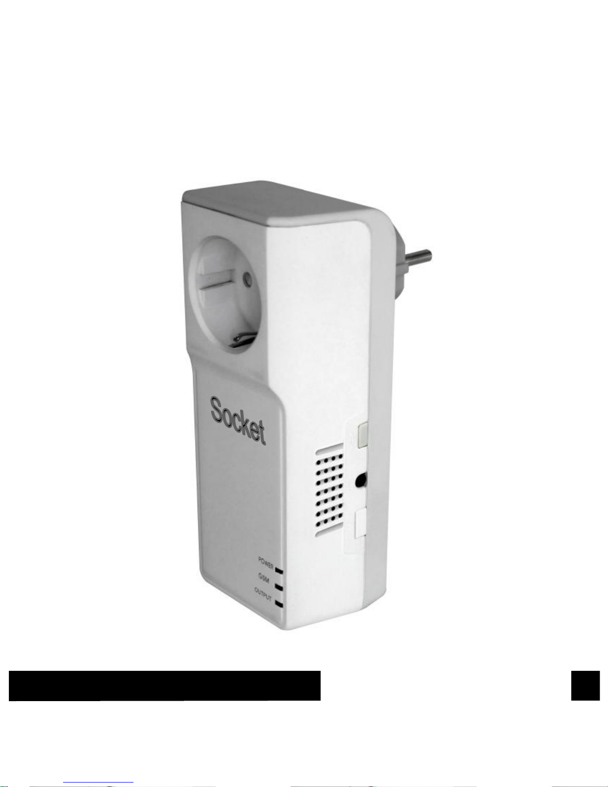
GSM Power Socket
User Manual
Page 2

GSM POWER SOCKET USER MANUAL
2
GSM Power Socket
Thank you for purchasing the GSM Power Socket .
GSM Power Socket is a remote controlled socket consisting of a GSM
module. The power supply output of the socket can be turned on or off
remotely by the SMS (Short Message System) command or local
controlled by pressing button. It is an intelligent power supply socket
controlled by users’ mobile phone at anytime and anywhere.
GSM Power Socket is suitable for controlling electrical appliances which
power consumption less than 3000W in household or office. It is
universal for all kinds of indoor power supply sockets.
With extended-connected temperature sensor, GSM power socket can
switch on or off the socket output according to the environment
temperature. It’s available for power control of the heating or
refrigeration plant, to keep the environmental temperature within
presetting range or at a fixed temperature value. Furthermore, a SMS
notification will be sent to master’s mobile phone if GSM Power Socket
detects the rapid-changing or the reaching of pre-set alert value of
surroundings temperature.
GSM Power Socket is mainly applied for house and office usage. It is
not suited for industry application, especially in humidity or dust
condition.
All services and functions need to be supported by the GSM network
and a SIM card.
This brochure suits for GSM Power Socket model.
Details of the functioning and advanced operation of this socket are
described in this instruction manual.
Page 3

GSM POWER SOCKET USER MANUAL
3
For your safety ................................................................................ 5
Exception clause ............................................................................. 6
Chapter 1 Features and accessories .................................................... 7
1.1 Main function ................................................................ ............. 7
1.2 Package contents ................................................................ ...... 8
1.3 Sockets instructions ................................................................... 9
1.4 Light indicator and “Beep” warning tone ................................... 10
Chapter 2 Quick start .......................................................................... 12
2.1 Install the SIM card and temperature sensor ............................ 12
2.2 GSM Power on/ off .................................................................. 12
2.3 Add a Master number to the socket .......................................... 13
2.4 The regulation of time .............................................................. 14
2.5 Socket output switching on/off .................................................. 14
2.6 External power supply notification ............................................ 15
Chapter 3 Advanced settings .............................................................. 16
3.1 Define the users ...................................................................... 16
3.2 Change password .................................................................... 19
3.3 Switching on/off the socket output manually ............................. 19
3.4 Delayed-switch on/off the socket output ................................... 21
3.5 Timed switching on the socket output ....................................... 22
Page 4

GSM POWER SOCKET USER MANUAL
4
3.6 Auto-control the socket output by temperature ......................... 24
3.7 Temperature alarm ................................................................... 27
3.8 SMS notification upon the socket output changing ................... 28
3.9 SMS notification upon external power supply changing ............ 29
3.10 “Beep” warning tone............................................................... 29
3.11 Check status .......................................................................... 30
3.12 Resetting the socket .............................................................. 32
Chapter 4 Maintenance ...................................................................... 33
Chapter 5 General Troubleshooting .................................................... 34
Chapter 6 Main Technical Parameters ................................................ 36
Appendix: SMS commands list ........................................................... 37
Page 5

GSM POWER SOCKET USER MANUAL
5
1. Purchase a GSM SIM card (mobile phone card) from
GSM network service provider and install it in the
socket. This SIM card number is referred as GSM Power
Socket number on this brochure.
2. The user needs to activate the Caller ID Presentation
function of SIM card, and deactivate PIN code of the
SIM. Contact with GSM network service provider for
support.
3. Change the original password at the beginning use. Be
sure to keep the password and SIM card number
secret. Do not disclose this information to anyone
other than the authorized users in order to ensure your
safety.
For your safety
This socket was designed for home or office use. Do not use it on
the electrical appliance which is for industry or business operation,
for example, iatrical appliances, large heaters and refrigerates.
Before using this socket, make sure that the mobile phones can be
used well in the area, otherwise, do not put this socket into
operation.
The power consumption of the appliances connected with the socket
cannot exceed 3000W and the current cannot exceed 16A.
The electrical appliance which power consumption is higher than
1500W must be grounded.
Do not make two plugs of socket short circuit.
Do not touch the socket jack by any metal objects or hand.
This socket was designed for indoor use. Don’t use it in wet,
chemically aggressive or dusty environment.
Page 6

GSM POWER SOCKET USER MANUAL
6
Do not open the case unless maintenance needed.
Do not keep shaking or fall down this socket, otherwise it can be
damaged.
This socket is a wireless signal transmission socket. Keep it away
from electronic equipment likely to interfere with the wireless signals,
in order to avoid signals interference.
Switch off this socket and mobile phone when entering areas
marked "Explosive", "Might explode", "Closed wireless transceiver
sockets" etc.
Do not cast this socket in a fire, as this may cause explosion.
This socket should only be operated from power approved by the
socket manufacturer. The use of any other types of power may
damage the socket.
Keep the socket and its accessories out of the children reach.
Exception clause
1. We operate on a policy of continuous development. We reserve the
right to make changes and improvements to any of the sockets
described in this document without prior notice.
2. We don’t guarantee for the document veracity, reliability or any
content except regulate in proper laws. Including no guarantee for
socket suitable market or suitable area promise.
3. We hold no responsibility for the illegal use of this socket.
4. We hold no responsibility for any loss of income or any special,
incidental, consequential or indirect damages howsoever caused.
5. The contents of this document are provided “as is”. Except as
required by applicable law, no warranties of any kind, either
expressed or implied, including, but not limited to the accuracy,
reliability or contents of this document. We reserve the right to revise
this document or withdraw it at any time without prior notice.
Page 7

GSM POWER SOCKET USER MANUAL
7
Chapter 1 Features and accessories
1.1 Main function
This socket uses a GSM SIM card.
Remotely operate by SMS command: The socket be controlled and
set by sending SMS commands.
Input: 110V-250V/50Hz.
Output: Max.16A for long-duration operation.
Relay: 30A/250V relay with two working status power on/off for
output outlet.
M button: To manual control output power on/off.
Delayed control socket output.
Auto operates by preset schedule: Fixing-time control output power
on/off.
External temperature sensor supported: Send environmental
temperature SMS to mobile phone.
Auto operates by temperature: Available for power control of the
heating or refrigeration plant, to keep the environmental temperature
within presetting range or at fixed temperature value.
SMS alarm when temperature rapid-changing or reaching the
pre-set value: When it detects the rapid-changing or the reach of
pre-set alert value of surroundings temperature, it can auto-send the
SMS alarm message to master’s mobile phone.
Support 5 mobile phone users.
Auto time-synchronization.
SMS notification upon external power source changing.
Page 8
GSM POWER SOCKET USER MANUAL
8
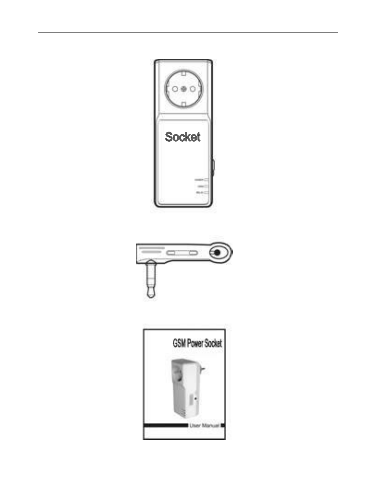
1.2 Package contents
GSM power socket(1 unit)
Temperature sensor(1 unit)
User manual(1 unit)
Page 9
GSM POWER SOCKET USER MANUAL
9
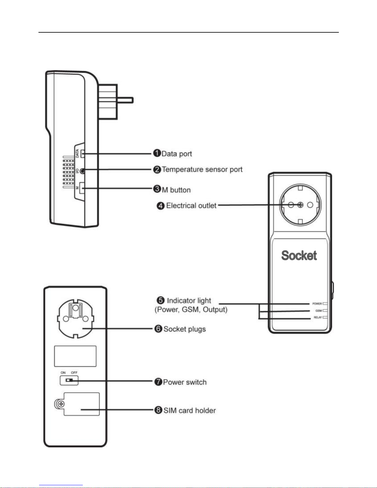
1.3 Sockets instructions
Figure 1: GSM Power Socket instructions
Page 10
GSM POWER SOCKET USER MANUAL
10
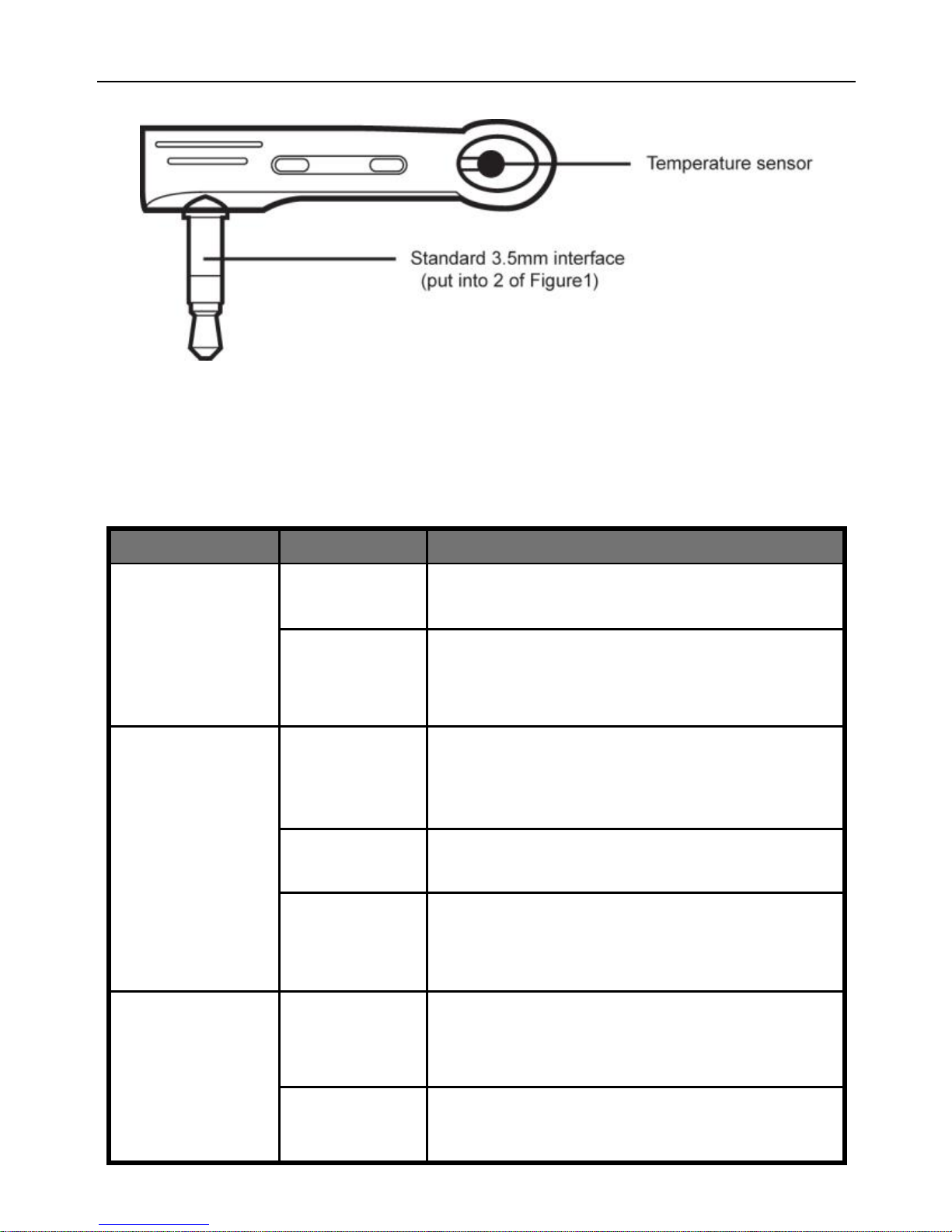
Figure 2: Temperature sensor Instruction
1.4 Light indicator and “Beep” warning tone
Indicator
Action
Status
Power
(Green) light
Turning off
No power supply input
Constant
light
Has power supply input
GSM (Blue)
light
Turning off
Not installed SIM card, or the power
switch of socket is “OFF”.
Flash
Be busy or searching GSM network.
Constant
light
Successfully load to GSM network.
Output (Red)
light
Constant
light
The socket outlet has power supply.
Turning off
The socket outlet cuts power supply.
Page 11
GSM POWER SOCKET USER MANUAL
11
“Beep”
warning tone
(Default
turning off)
One time
The socket outlet changes power
supply status.
Several
times
GSM Power Socket lost external
power supply.
Long Beep
GSM Power Socket is successfully
register GSM network, or it is
successfully reset to its factory
settings.
Note: The “Beep” warning tone can be turn on or turn off by SMS
command. Refer to Chapter 3.9 for details.
Page 12

GSM POWER SOCKET USER MANUAL
12
Chapter 2 Quick start
2.1 Install the SIM card and temperature sensor
Turn the power switch to “OFF” position.
Loosen the screw and open the socket’s SIM cover; you will see a
SIM card holder.
Push the metallic cover of the holder to “OPEN” direction and open
the SIM card holder.
Put the SIM card on the card holder, ensuring that the beveled
corner is toward the beveled corner of the SIM holder and the golden
contact area is facing downwards.
Cover back the metallic cover and push it to “LOCK” direction. The
SIM card will be fixed in the holder.
Screw the SIM cover back.
Insert the temperature sensor into the I/O port until it is seized.
2.2 GSM Power on/ off
Power on:
1. Turn the power switch to “On” position (See 7 on Figure1).
2. Plug the GSM Power Socket in an AC power socket (See 6 on
Figure1).
The blue light will be flashing slowly for about 20 seconds, then blue
light be on constantly and a long “Beep” tone can be heard (if “Beep”
warning tone is enabled).
The default state of the socket outlet is no power supply output.
3. Insert the plug of electronic appliance in the GSM Power Socket
electrical outlet (See 4 on Figure1).
Page 13

GSM POWER SOCKET USER MANUAL
13
4. M button (See 3 on Figure1) can be pressed for about 0.5 second to
switch on or off the output of socket.
After adding user numbers to the socket, users can send SMS
command to control the power supply output. (Refer to Chapter 3.2)
Power off:
1. Turn the power switch to “Off” position. The blue light turns off.
2. The socket outlet can work as a normal power socket. GSM Power
Socket can not be controlled by SMS commands. M button is
disabled.
Note:
1. If the GSM indicator light is not constant lights, which imply
the SIM card working abnormally, all functions of this socket
are invalid.
2. Check GSM network signal of the using place:
The GSM network’s signal strength may affect the socket
feature. Therefore, before using, the user should ensure
that GSM Power Socket is used in an area with a strong
GSM network signal.
For the first time use, the user should perform a test-run
by sending SMS to the socket. This allows the user to
check the GSM network connection of the socket.
2.3 Add a Master number to the socket
The user must edit and send the following SMS to socket via his/her
mobile phone (the phone number will be the Master number) in order to:
Add a Master number to the socket: #00#
Successful SMS reply
Welcome to use GSM Power Socket.
Your Password is:1234.
Page 14

GSM POWER SOCKET USER MANUAL
14
2.4 The regulation of time
Important note
If GSM Power Socket is being used for the first time, or it has been
reset, the Master user must adjust the socket time according to
the current time of SMS center. Otherwise, GSM Power Socket will
use the original time from 00:00:00, 1st.Jan.2004.
Method
The Master user sends following SMS message in order to:
Regulate the socket time: #152#SIMCardNumber# (1)
The SIMCardNumber should be the SIM card number of GSM
Power Socket .
Successful SMS reply
The socket current time is yyyy/mm/dd hh:mm.
2.5 Socket output switching on/off
Method
Method 1:To press M button 0.5 second (See 3 on Figure1).
Method 2:
The Master user sends following SMS message to socket in order to:
Switch on the socket output: #01#
Switch off the socket output: #02#
Successful SMS reply
Status: ON/OFF
Temp:**
Temp control: function ON/OFF
Schedule control: function ON/OFF
Delay control: function OFF
Page 15

GSM POWER SOCKET USER MANUAL
15
2.6 External power supply notification
GSM Power Socket will notify the user when the external power changes.
The “Beep, Beep…” tones will be heart (if enabled), also a SMS
notification will be sent if the SIM card is available:
Lost external power supply:
If the plug of GSM Power Socket is disconnected from external AC power
or lost of the AC power occurs, all operating on GSM Power Socket is
de-activated, including M button and all SMS commands. GSM Power
Socket will notify the user “Main electricity supply lost Temp:**”.
Resume external power supply:
If the AC power of GSM Power Socket is available again, the SMS
notification will be sent to the user, i.e.” Main electricity supply restore
Status: ON/OFF Temp:**”
When the external power supply is resumed, the output of GSM Power
Socket will keep its previous working status. For example, if the output is
switched on before the external power supply cut off, the output will be
switched on when the external power supply is resumed.
If the power supply is switched on and off frequently, GSM Power Socket
will send reminding SMS messages.
The SMS notification upon external power supply changing can be
disabled. (Refer to Chapter 3.8)
Page 16

GSM POWER SOCKET USER MANUAL
16
Chapter 3 Advanced settings
3.1 Define the users
3.1.1 User authorization level
All the settings of GSM Power Socket can be set or adjusted via a SMS
command.
There are two mobile phone user controlling levels:
Master user:
Only one Master user has authorization to use all features of GSM
Power Socket.
In order to enable all the functions on the socket, the Master user
must store his/ her mobile number in the socket’s memory. Only one
Master’s mobile number (Master number) is allowed for a socket.
Family users:
There are four Family users have authorization to use two
commands of switch on or cut off the socket output.
The other mobile phone users have no authorization to use GSM
Power Socket .
3.1.2 About the SMS Command
Master user’s SMS command format: #code#content#.
Family users’ SMS command format: #code#content#password#.
The password must be a four-digit number.
The original password is 1234.
The maximum digits that are allows for the phone number is sixteen.
Page 17

GSM POWER SOCKET USER MANUAL
17
GSM Power Socket will reply to the user after it receives the SMS
command.
Note
The “#” symbol must not be ignored when typing an SMS
command.
No allow any space within the commands.
3.1.3 Add a master number to the socket
Description
If GSM Power Socket is being used for the first time, or GSM Power
Socket has been reset to factory settings, the Master user’s
number must be programmed into the socket.
Method
The user must edit and send the following SMS to socket via
his/her mobile phone (the phone number will be the Master
number) in order to:
Add a master number to the socket: #00# (2)
Successful SMS reply
Welcome to use GSM Power Socket.
Your Password is:1234..
Failed SMS reply
If a user tries to add another Master user again, GSM Power
Socket will send a notification via SMS stating “The master user
already exists.”. The Master number should be changed. (Refer
to Chapter 3.1.4)
3.1.4 Change the master number
Method
Method 1:
The Master user sends following SMS message in order to:
Change the master user’s number: #14#NewMasterNumber (3)
Page 18

GSM POWER SOCKET USER MANUAL
18
NewMasterNumber should be the new Master user’s
mobile phone number.
Method 2:
GSM Power Socket should be reset to factory settings to remove
old Master number before setting the new one. (Refer to Chapter
3.11)
Successful SMS reply
New master number set successfully.
Successful SMS reply will be sent to the new Master user. Then
the old Master user’s number will not be able to control GSM
Power Socket anymore.
3.1.5 Add a family number
Up to 4 family users’ number can be stored on one socket.
Family users have the authority to send SMS command to switch on or
cut off the GSM Power Socket output. The family users should remember
and safeguard the socket’s SIM number.
Method
The Master user sends following SMS message in order to:
Add a family number:
#06#FamilyNumber# (4)
Add several family numbers:
#06#FamilyNumber1#...#FamilyNumber4# (5)
FamilyNumber should be the Family user’s mobile phone
number.
Successful SMS reply
#******# Family numbers set successfully.
3.1.6 Check family user’s number
Refer to Chapter 3.10 Check status.
Page 19

GSM POWER SOCKET USER MANUAL
19
3.1.7 Delete family number
Method
The Master user sends following SMS message in order to:
Delete a family number: #113#FamilyNumber# (6)
Delete several family numbers simultaneously:
#113#FamilyNumber1#…#FamilyNumber4# (7)
Delete all family numbers: #113# (8)
Successful SMS reply
#******# Family number has been deleted.
Failed SMS reply
#******# The family number does not exist.
3.2 Change password
Method
The Master user sends following SMS message in order to:
Change the password: #04#Oldpassword#Newpassword# (9)
The password is a four digit number.
The original password is 1234.
Successful SMS reply
New password is ****.
3.3 Switching on/off the socket output manually
Description
When the socket output is switching on, GSM Power Socket offers
power supply for electronic appliance which being connected with it;
the red indicator light is lighted constantly. Otherwise, GSM Power
Socket has no power supply for electronic appliance and the red light
is turned off.
Note: If the socket output status is changed manually (including
pressing the M button, sending SMS, making phone call), the preset
timing, delaying or temperature control of the socket will be invalid
Page 20

GSM POWER SOCKET USER MANUAL
20
automatically and a SMS notification message will be sent to the
Master, but the setting time range and temperature range
parameters will be saved until GSM Power Socket is reset to factory
settings.
3.3.1 Switching on/off by SMS
Method
The Master user sends following SMS message in order to:
Switch on the socket output manually: #01# (10)
Cut off the socket output manually: #02# (11)
The Family users send following SMS message in order to:
Switch on the socket output manually: #01#Password# (12)
Cut off the socket output manually: #02#Password# (13)
Password should be 4 digits password number. Default 1234.
SMS reply will be also sent to Master user when Family users use
these two commands to change the socket output successfully.
Successful SMS reply
Status: ON/OFF
Temp:**
Temp control: function ON/OFF
Schedule control: function ON/OFF
Delay control: function ON/OFF
3.3.2 Switching on/off by M button
Keep press M button on the GSM Power Socket for half a second.
The OUTPUT indecator light will turn on or off to indicate that
GSM Power Socket output is switching on or off.
The SMS reply is same with Chapter 3.2.1.
3.3.3 Switching on/off by calling
Description
If the Master user calls GSM Power Socket , the socket output will
Page 21

GSM POWER SOCKET USER MANUAL
21
be switched on or cut off automatically when the user hears the
ring tone in the phone. The calling will be hung up automatically if
the user doesn’t hang up the call.
Method
The Master user sends following SMS message in order to:
Enable switching on/off the output by calling:
#18#1# (14)
Disable switching on/off the output by calling (Default):
#18#0# (15)
Successful SMS reply
Control the socket power output status by calling activated
/de-activated.
3.4 Delayed-switch on/off the socket output
Description
The output of GSM Power Socket can be set to delay switch on or off
for a period with SMS commands.
When the “delayed-switch on/off the socket” function is applied, the
preset “timed switch on the output” function will be invalid at once.
When the “delayed switch on the socket” command is received and
if the socket output is switched on, the socket output will be switched
off immediately and be switch on again as the setting delayed time is
reaching. Contrarily, if the socket output is switched off, the output
will remain switching off until the setting delayed time is reaching.
Afther switching on the output, the following SMS reply will be sent:
Status: ON
Delay control: function OFF
When the “delayed switch off the socket” command is received and if
the the socket output is switched on, the socket output will remain
the switch on state and be switched off as the setting delayed time is
reaching. If the socket output is switched off, it will be switched on
Page 22

GSM POWER SOCKET USER MANUAL
22
immediately and be switch off again when reaching the setting
delayed time. After switching off the socket output, the following
SMS reply will be sent:
Status: OFF
Delay control: function OFF
Method
The Master user sends following SMS message in order to:
Delay switching on the output after a certain minutes:
#138#1#Minutes# (16)
Delay switching off the output after a certain minutes:
#138#0#Minutes# (17)
Minutes are time parameters, its range is 0-720,
When Minutes is 0, the “delayed switch on/off the socket” function
will be invalid, but the current output status won’t be changed.
Successful SMS reply
Status: ON/OFF
Output will switch off/on after * minutes.
3.5 Timed switching on the socket output
3.5.1 Enable timing switching on the output
Description
The output of GSM Power Socket can be set to switch on for a
duration and then be switch off after the duration.
If the socket output status is changed manually (including pressing
M button, sending SMS and making phone call), the preset timing,
delaying or temperature control of the socket will be invalid
automatically, but the setting time range parameters will be saved
until GSM Power Socket is reset to factory settings. If these functions
need to be restarted, the following SMS commands must be set:
Timing #128#1#, Temperature control #159#1#, “delayed switch
on/off the socket” commands need to be reset.
Page 23

GSM POWER SOCKET USER MANUAL
23
Method
The Master user sends following SMS message in order to:
Enable timing switch on the output: #128#1# (18)
Successful SMS reply
Schedule control: function ON
WorkDay, StartTime-EndTime
If the value of the “WorkDay, StartTime, EndTime” on the SMS
reply are all 0, it means the time duration has not been set. (Refer
to 3.4.2)
Then GSM Power Socket will keep switching on or off the output
automatically according to the schedule settings.
3.5.2 Set time period to switch on the output
Description
After successful setting of time duration to switch on the socket
output, the schedule parameter will be saved on the socket until
GSM Power Socket is reset to factory settings.
But the “timed switch on the output” feature is applied only when
command 17 be set.
Method
The Master user sends following SMS message in order to:
Set time period to switch on the output:
#129#WorkDay#StartTime#EndTime# (19)
WorkDay: one digit, the values lie in the range of “0” to “8”.
The following table contains the descriptions of each value:
Value
Corresponding day
0
Sunday
1
Monday
2
Tuesday
3
Wednesday
4
Thursday
Page 24

GSM POWER SOCKET USER MANUAL
24
5
Friday
6
Saturday
7
Everyday
8
Monday to Friday
StartTime and EndTime: Be consists of 4 digits (hh:mm) and works
on a 24 hour clock. The StartTime and EndTime should be in the
same day, and the EndTime must be later than StartTime.
The socket output will switch on at the StartTime and cut off at the
EndTime.
For example: #129#1#0000#2130# , 0000 means time
00:00(hh:mm)AM, 2130 means time 9:30PM.
Successful SMS reply
Schedule control: function ON/OFF
WorkDay, StartTime-EndTime
3.5.3 Disable timing switching on the output
Method
The Master user sends following SMS message in order to:
Disable timing switch on the output: #128#0# (20)
Successful SMS reply
Schedule control: function OFF
WorkDay, StartTime-EndTime.
3.6 Auto-control the socket output by temperature
3.6.1 Enable auto-controlled by temperature
Description
The external temperature sensor must be inserted into the I/O port
of GSM Power Socket. The output status of the socket can be
controlled by the environmental temperature automatically.
If users don’t open the “timed switch on the socket” or “delayed
Page 25

GSM POWER SOCKET USER MANUAL
25
switch on/off the socket” functions, the socket will control to switch
on or cut off the output according to temperature setting.
If users open the “timed switch on the socket” or “delayed switch
on/off the socket” functions, the temperature control function will only
be valid when power output is switch on (including timed switch on
or delayed switch on time period).
For example: GSM Power Socket is used for the power control of the
heating apparatus. If users set the socket output on when indoor
temperature is bellow 20 degrees and off when indoor temperature
is above 28 degrees. Meanwhile, users set the GSM Power Socket
output is on from 9am to 5pm. In this case, the socket will control to
switch on or off the output according to indoor temperature
automatically from 9am to 5pm duration.
Method
The Master user sends following SMS message in order to:
Enable auto-control the output by temperature: #159#1# (21)
Successful SMS reply
Status: ON/OFF
Temp control: function ON
Temp: **
Mode: Heating/Cooling
Range: LowTemp ~ HighTemp
Then GSM Power Socket can switch on or off the output
automatically according to the temperature range setting.
3.6.2 Set temperature range to switch on/off the output
Description
After successful setting of temperature range, the temperature
parameter will be saved on the socket until GSM Power Socket is
reset to factory settings.
But the “Auto-controlled by temperature” feature is applied only
Page 26

GSM POWER SOCKET USER MANUAL
26
when command 20 be set.
Method
The Master user sends following SMS message in order to:
Set temperature range to switch on/off the output:
#159#Mode#LowTemp#HighTemp# (22)
Mode is the control selection:
For coldness, mode=1. For warmness, mode=0.
LowTemp and HighTemp means temperature value, the range is
-10 to 50 centigrade degree, if LowTemp equals to HighTemp,
constant temperature control will be actived.
Temperature unit is degree Celsius.
Example 1: set commands: #159#0#10#20#, if the environmental
temperature is 5 degrees (bellow the limitation of 10 degrees in the
command), the socket output will be switched on to power heating
apparatus; and if the environmental temperature is 24 degrees
(above the limitation of 20 degrees in the command), the socket
output will be switched off and the heating apparatus stops working;
Example 2: set commands: #159#1#10#20#, if the environmental
temperature is 26 degrees (above the limitation of 20 degrees in the
command), the socket output will be switched on to power cooling
apparatus; and when the environmental temperature is 7 degrees
(bellow the limitation of 10 degrees in the command), the socket
output will be off, cooling apparatus stops working.
Successful SMS reply
Status: ON/OFF
Temp control: function ON/OFF
Temp: **
Mode: Heating/Cooling
Range: LowTemp ~ HighTemp
3.6.3 Disable auto-controlled by temperature
Method
The Master user sends following SMS message in order to:
Page 27

GSM POWER SOCKET USER MANUAL
27
Disable auto-control the output by temperature: #159#0# (23)
Successful SMS reply
Status: ON/OFF
Temp control: function OFF
Temp: **
Mode: Heating/Cooling
Range: LowTemp ~ HighTemp
3.7 Temperature alarm
3.7.1 Over-temperature alarm
Description
A range of temperature can be pre-set onto the socket. In this case,
if the surroundings temperature is detected out of the pre-set
temperature range, the GSM Power Socket will auto-send the SMS
alarm message to master’s mobile phone.
This feature depends on the temperature sensor.
Method
The Master user sends following SMS message in order to:
Enable over-temperature alarm: #170#1# (24)
Set limits of temperature: #170#MinTemp#MaxTemp# (25)
MinTemp and MaxTemp: The values can be set within the range of
-10 to 50 centigrade degree.
Default MinTemp is 20 and MaxTemp is 30 centigrade degree.
Disable the alarm upon going beyond limits temperature:
#170#0# (26)
Successful SMS reply
Temperature alert: function ON/OFF
Min Temp.:**
Max Temp.: **.
Page 28

GSM POWER SOCKET USER MANUAL
28
3.7.2 Temperature rapid-changing alarm
Description
A time period value and temperature changing value can be pre-set
onto the socket. In this case, if the surroundings temperature change
to the pre-set value within the pre-set time period, a SMS alarm
message will be auto-sent to master’s mobile phone.
This feature depends on the temperature sensor.
Method
The Master user sends following SMS message in order to:
Enable the temperature rapid changing alarm: #160#1# (27)
Set time period and temperature changing value:
#160#Temp#Time# (28)
Temp: The values lie in the range of 1 to 50 centigrade degree.
Time: The values lie in the range of 1 to 300 minutes.
Default Temp is 2 degree and Time is 1 minute.
Disable the temperature rapid changing alarm: #160#0# (29)
Successful SMS reply
Fast temperature changing.: function ON/OFF
Delta:**
Time:* minutes
3.8 SMS notification upon the socket output changing
Description
GSM Power Socket will default notify the user when the state of the
socket output is changed with a SMS notification. The Master user
can enable/disable this SMS notification.
Method
The Master user sends following SMS message in order to:
SMS notification upon the socket output changing (Default):
#11#1# (30)
No SMS notification upon the socket output changing:
#11#0# (31)
Page 29

GSM POWER SOCKET USER MANUAL
29
Successful SMS reply
Set no SMS notification when socket output changed.
Set SMS notification once socket output changed.
3.9 SMS notification upon external power supply
changing
Description
GSM Power Socket will default notify the user when the state of the
external power supply is changed with a SMS notification. For
example:
Main electricity supply lost
Temp:**
or
Main electricity supply restore
Status: ON
Temp:**
The Master user can enable/disable this SMS notification.
Method
The Master user sends following SMS message in order to set:
SMS notification upon the power supply changing (Default):
#12#1# (32)
No SMS notification upon the power supply changing: #12#0# (33)
Successful SMS reply
(No) SMS notification upon main electricity supply changing.
3.10 “Beep” warning tone
Description
A “Beep” warning tone will be sounded if the work state of GSM Power
Socket is changed. The “Beep” warning tone is default turning off.
The Master user can enable it by sending SMS command.
Method
Page 30

GSM POWER SOCKET USER MANUAL
30
The Master user sends following SMS message in order to:
Enable the “Beep” warning tone: #19#1# (34)
Disaable the “Beep” warning tone (Default): #19#0# (35)
Successful SMS reply
Beep alarm activated/de-activated.
3.11 Check status
Method
The Master user sends following SMS message in order to:
Check socket operating status: #07# (36)
After receiving the SMS commands, GSM Power Socket will reply one
SMS message of socket status checking:
Number:***********,**********
Status: ON/OFF
TEMP:**
Temp control:function ON/OFF
Schedule control:function ON/OFF
Delay control:function ON/OFF
Check socket output status: #000# (37)
After receiving the SMS commands, GSM Power Socket will reply one
SMS message of socket output status:
Status: ON
Temp:23.
Check “delayed switch on/off the socket” parameters: #138# (38)
After receiving the SMS commands, GSM Power Socket will reply one
SMS message of “Delayed switch on/off the socket” parameters
checking:
Status: ON/OFF
Output will switch off/on after ** minutes.
Check “Timing switch on the socket” parameters: #128# (39)
After receiving the SMS commands, GSM Power Socket will reply one
Page 31

GSM POWER SOCKET USER MANUAL
31
SMS message of “Timing switch on the socket” parameters:
Schedule control: function ON/OFF
WorkDay, StartTime-EndTime.
Check “Temperature control” parameters: #159# (40)
After receiving the SMS commands, GSM Power Socket will reply one
SMS message of temperature parameters checking:
Status: ON/OFF
Temp control: function ON/OFF
Temp: **
Mode: Heating/Cooling
Range: LowTemp ~ HighTemp
If “No temperature sensor connected” be received, it means GSM
Power Socket cannot detect the temperature sensor. User needs to
check if the temperature sensor is inserted to the I/O port.
Check “temperature rapid changing alarm” parameters: #160# (41)
After receiving the SMS commands, GSM Power Socket will reply one
SMS message of parameters. It means SMS alarm message will be
sent upon the surrounding temperature changes “Delta” centigrade
degree within * minutes:
Fast temperature changing.: function ON/OFF
Delta: *
Time: * minutes
Check “over-temperature alarm limits” parameters: #170# (42)
After receiving the SMS commands, GSM Power Socket will reply one
SMS message of parameters. It means SMS alarm message will be
sent upon temperature reaches MinTemp or MaxTemp centigrade
degree:
Temperature alert: function OFF
Min Temp.: **
Max Temp.: **
Page 32

GSM POWER SOCKET USER MANUAL
32
3.12 Resetting the socket
Description
This function resets all programmed settings to their original values,
including cleaning all user number, timing parameter and
temperature parameter.
If the setting status is wrong or the malfunctions can’t be
corrected, users can restore the socket to its original status to make
it work normally.
Note
This function needs to be used carefully as it also erases all setting
values.
Method
Method 1: Press the side M button of the device for 5 seconds.
Method 2: The Master user sends following SMS message to GSM
Power Socket in order to:
Reset the socket: #08# (43)
Successful SMS reply
Reset the socket to factory setting successfully.
A long “Beep” tone (if enabled) will be heard and it means resetting
the socket successfully.
Page 33

GSM POWER SOCKET USER MANUAL
33
Chapter 4 Maintenance
If GSM Power Socket does not in use for long time, it
should be powered off.
Store and use the remote socket in suitable temperature.
Too high or too low temperature will likely to damage the
socket.
Try to keep the GSM Power Socket and all its accessories
dry. Do not store and use it in the bathroom, or other
place with high humidity. Do not allow pour water or other
liquids into the socket, otherwise, it might cause
malfunctions.
Do not store and use the socket in dusty.
Do not use alcohol, acetone and other similar solvents to
clean it. Wipe it with soft-wet cloth.
Do not attempt to open it except as instructed. If the
socket does not work normally, try to resolve it as the
guide of the "general troubleshooting", if to the problem
can not be solved, contact with the dealer immediately.
Page 34

GSM POWER SOCKET USER MANUAL
34
Chapter 5 General Troubleshooting
No.
General
Trouble
Possible Reason
Solution
1
Power
indicator light
turns off
No power input.
Check GSM Power
Socket ’s external AC
power is available.
2
GSM
indicator light
turns off
Can’t find or identify
the SIM card.
The power switch is
OFF.
SIM card no install
properly: Power off
the socket and check
it again.
Power on the socket.
3
Socket
output cannot
be changed
by M button.
No power input.
The power switch is
OFF.
Check GSM Power
Socket’s external AC
power is available.
Power on the socket.
4
All functions
disable
(Indicator is
working)
Caller ID
presentation do not
active, insufficient
fee of the SIM card.
Contact network
provider to active SIM
card function. Pay for
the card.
5
Socket didn’t
response of
any
operation.
GSM Power Socket
work abnormally.
Switch off the power,
check SIM card, or
reset factory setting.
6
After power
on the
socket, GSM
indicator
keeps
flashing.
Network signal
weak or network
busy.
If mobile phone’s
signal is weak too,
place the socket at
other place with
strong signal and try
again.
Page 35

GSM POWER SOCKET USER MANUAL
35
No.
General
Trouble
Possible Reason
Solution
SIM card PIN code
actives.
Close the PIN code.
SIM card invalid.
Contact with local
operator to check of it.
7
The master
number
already
exists.
Other master is
already set in the
socket.
Change Master
number or recover to
factory default setting.
8
Invalid
format.
Please check
and try again.
Invalid command.
Refer to the user
manual.
9
No
authorization
user
Use the Master
mobile phone to try
the command again.
Note: If the problem can’t be solved with above guidelines, contact to
your local distributor or after service center.
Page 36

GSM POWER SOCKET USER MANUAL
36
Chapter 6 Main Technical Parameters
Input power socket
110~230V/50HZ,
CEE 7/7 hybrid Schuko/French plug
Output power socket
110~ 230V/50HZ, 230V/30A(30s),
16A long-duration,
CEE7/4 German “Schuko”
Operating temperature
-10℃~+50℃
Store temperature
-20℃~+60℃
Relative humidity
10-90%,without condensation
Communication
protocols
GSM PHASE 2/2+
(including data operation)
Data interface
GSM SIM 1.8V/3.0V socket
External temperature
sensor
-10℃~50℃
GSM working band
GSM850, EGSM900,
DCS1800 ,PCS1900 Optional
Page 37
GSM POWER SOCKET USER MANUAL
37
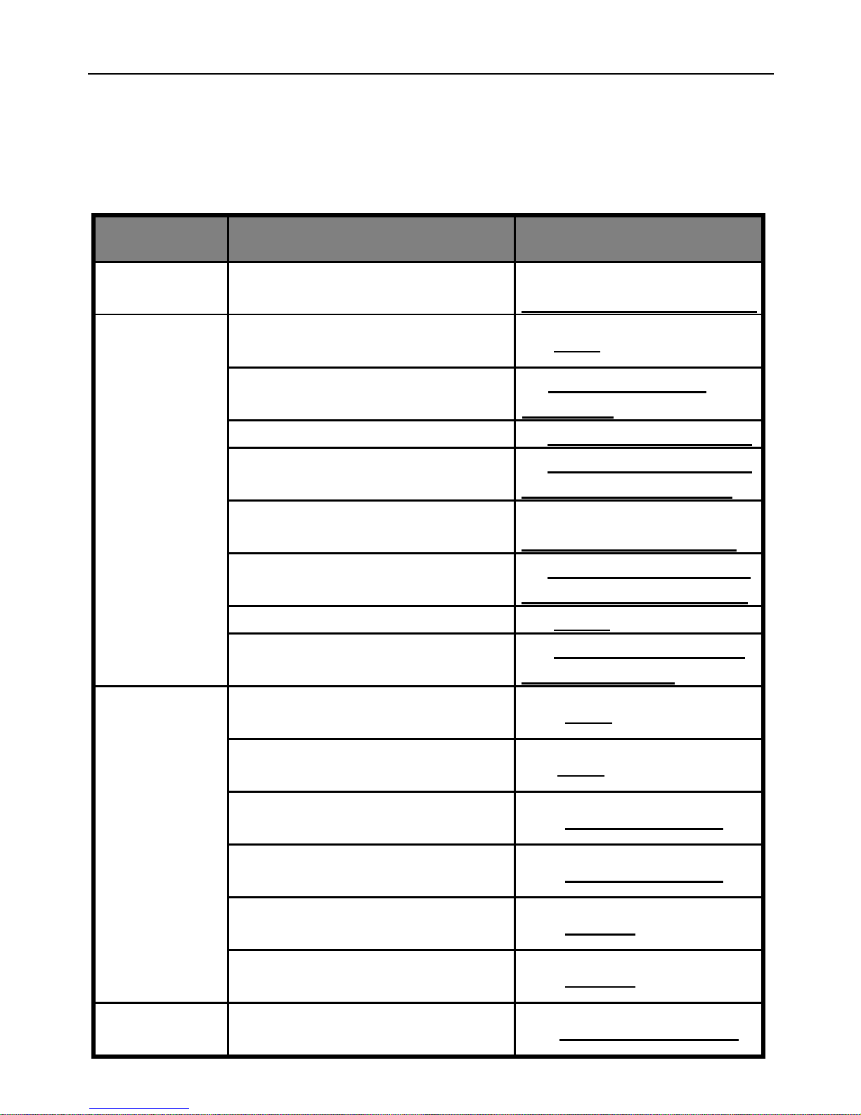
Appendix: SMS commands list
Category
Function
Command
Time
Regulate the socket time
(1)
#152#SIMCardNumber#
Define the
users
Add a master number to the
socket
(2) #00#
Change the master user’s
number
(3)#14#NewMaster
Number#
Add a family number
(4)#06#FamilyNumber#
Add several family numbers
(5)#06#FamilyNumber1
#...#FamilyNumber4#
Delete a family number
(6)
#113#FamilyNumber#
Delete several family
numbers simultaneously
(7)#113#FamilyNumber
1#…#FamilyNumber4#
Delete all family numbers
(8) #113#
Change the password
(9) #04#Oldpassword#
Newpassword#
Switching
on/off
output
manually
Master user switches on the
socket output manually
(10) #01#
Master user cuts off the
socket output manually
(11)#02#
Family user switches on the
socket output manually
(12) #01#Password#
Family user cuts off the
socket output manually
(13) #02#Password#
Enable switching on/off the
output by calling
(14) #18#1#
Disable switching on/off the
output by calling (Default)
(15) #18#0#
Delay
control
Delay switching on the output
after a certain minutes
(16) #138#1#Minutes#
Page 38
GSM POWER SOCKET USER MANUAL
38
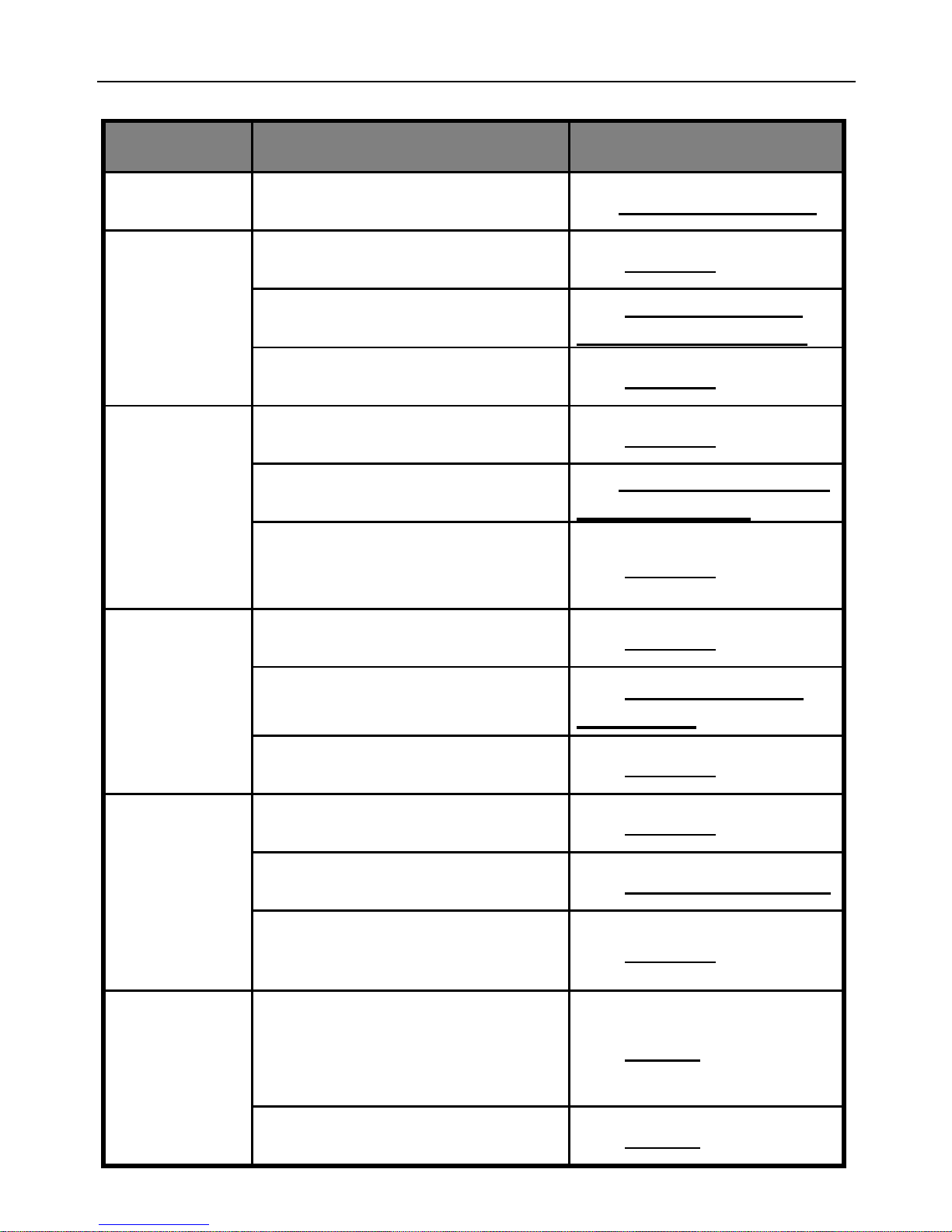
Category
Function
Command
Delay switching off the output
after a certain minutes
(17) #138#0#Minutes#
Timing
control
Enable timing switch on the
output
(18) #128#1#
Set time period to switch on
the output
(19) #129#WorkDay#
StartTime#EndTime#
Disable timing switch on the
output
(20) #128#0#
Temperatu
re control
Enable auto-control the
output by temperature
(21) #159#1#
Set temperature range to
switch on/off the output
(22)#159#Mode#LowTe
mp#HighTemp#
Disable auto-control the
output by temperature
(23) #159#0#
Over-
temperatur
e alarm
Enable the over-temperature
alarm
(24) #170#1#
Set limits of temperature
(25) #170#MinTemp#
MaxTemp#
Disable the over-temperature
alarm
(26) #170#0#
Temperatu
re rapid-
changing
alarm
Enable the temperature
rapid-changing alarm
(27) #160#1#
Set time period and
temperature changing value
(28) #160#Temp#Time#
Disable the temperature
rapid-changing alarm
(29) #160#0#
SMS
notification
SMS notification upon the
socket output changing
(Default)
(30) #11#1#
No SMS notification upon the
socket output changing
(31) #11#0#
Page 39
GSM POWER SOCKET USER MANUAL
39
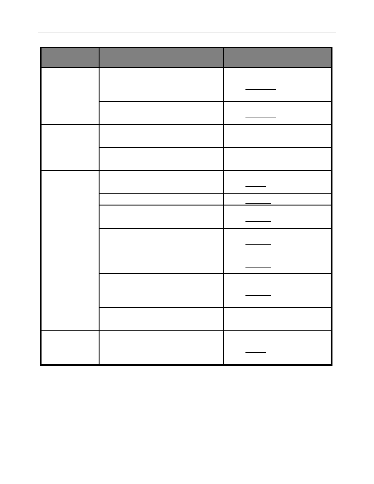
Category
Function
Command
SMS notification upon the
power supply changing
(Default)
(32) #12#1#
No SMS notification upon the
power supply changing
(33) #12#0#
“Beep”
warning
tone
Enable the “Beep” warning
tone
(34) #19#1#
Disaable the “Beep” warning
tone (Default)
(35) #19#0#
Check
status
Check socket operating
status
(36) #07#
Check Socket output status
(37) #000#
Check “Delayed switch on/off
the socket” parameters
(38) #138#
Check “Timed switch on the
socket” parameters
(39) #128#
Check “Temperature control”
parameters
(40) #159#
Check “temperature
rapid-changing alarm”
parameters
(41) #160#
Check “over-temperature
alarm” parameters
(42) #170#
Reset to
factory
settings
Reset the socket
(43) #08#
Page 40

GSM POWER SOCKET USER MANUAL
40
GSM Power Socket
 Loading...