

Page 1
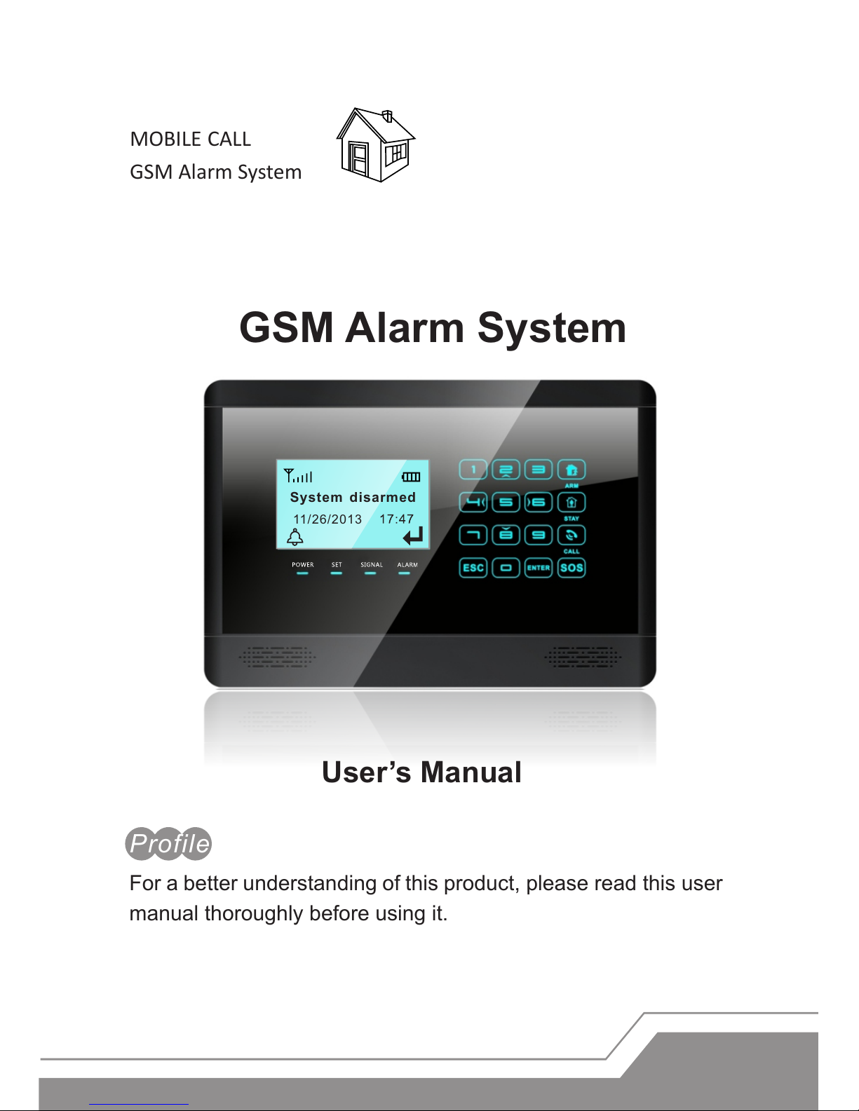
GSM Alarm System
MOBILE CALL
GSM Alarm System
For a better understanding of this product, please read this user
manual thoroughly before using it.
Profile
User’s Manual
Syst em disarmed
11/26/2013
Page 2
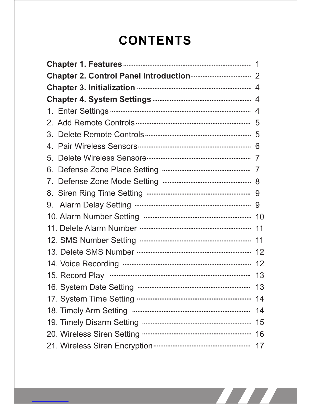
CONTENTS
Chapter 1. Features
Chapter 2. Control Panel Introduction
Chapter 3. Initialization
Chapter 4. System Settings
1.
2. Add Remote Controls
3. Delete Remote Controls
4. Pair Wireless Sensors
5. Delete Wireless Sensors
6. Defense Zone Place Setting
7. Defense Zone Mode Setting
8. Siren Ring Time Setting
9. Alarm Delay Setting
10. Alarm Number Setting
11. Delete Alarm Number
12. SMS Number Setting
13. Delete SMS Number
14. Voice Recording
15. Record Play
16. System Date Setting
17. System Time Setting
18. Timely Arm Setting
19. Timely Disarm Setting
20. Wireless Siren Setting
21. Wireless Siren Encryption
Enter Settings
1
2
4
4
4
5
5
6
7
7
8
9
9
10
11
11
12
12
13
13
14
14
15
16
17
Page 3
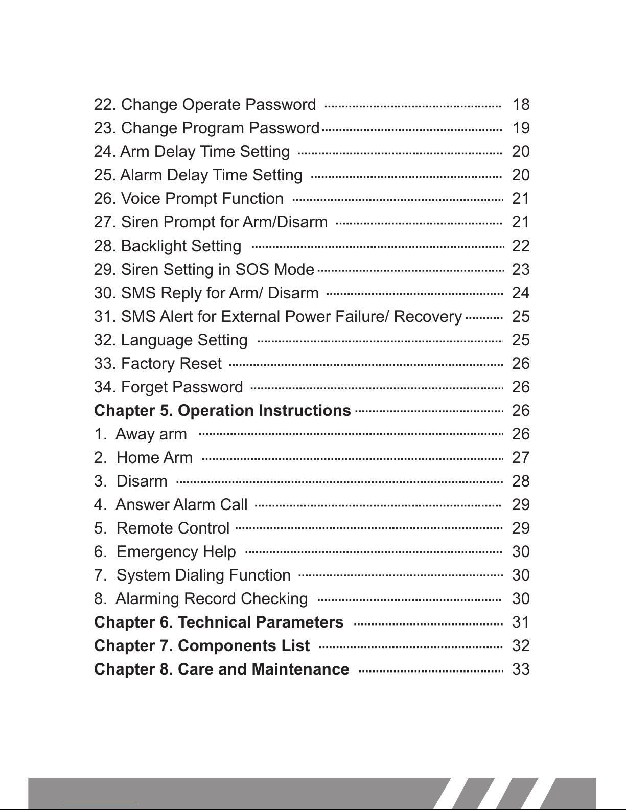
22.
23. Change Program Password
24. Arm Delay Time Setting
25. Alarm Delay Time Setting
26. Voice Prompt Function
27. Siren Prompt for Arm/Disarm
28. Backlight Setting
29. Siren Setting in SOS Mode
30. SMS Reply for Arm/ Disarm
31. SMS Alert for External Power Failure/ Recovery
32. Language Setting
33. Factory Reset
34. Forget Password
Chapter 5. Operation Instructions
1. Away arm
2. Home Arm
3. Disarm
4. Answer Alarm Call
5. Remote Control
6. Emergency Help
7. System Dialing Function
8. Alarming Record Checking
Chapter 6. Technical Parameters
Chapter 7. Components List
Chapter 8. Care and Maintenance
Change Operate Password
18
19
20
20
21
21
22
23
24
25
25
26
26
26
26
27
28
29
29
30
30
30
31
32
33
Page 4
1
Features
Elegant and advanced touch keypad for easy operation;
128x64 lattice LCD screen with clock display;
4 wired and 10 wireless defense zones; each wireless zone supports
maximum 10 sensors;
Support maximum 8 remote controls;
One relay switch: it will be connected when alarming;
Built-in high-volume speaker, and artificial intelligent digital voice
announcer;
Built-in artificial intelligent English message;
10-second automatic voice message recording;
Can preset 6 phone numbers: when alarming, system will make audio
call to these numbers automatically;
Can preset 3 SMS numbers: when alarming, system will send SMS;
Timely arm and disarm;
Can be used as a wireless telephone by using keypad to make calls;
One-key-control: out arm, home arm, arm by remote controller or
phone call;
SOS, fire, gas, door, hall, window, balcony, and boundary places
alarm;
Real-time, delay, 24 hours, bypass defense zones programming
function;
Wireless learning code: easy to add additional wireless accessories;
Remote control the device to arm, disarm, monitor, and intercom by
phone;
Record checking: the device can store 30 alarm records;
Built-in LI battery: automatically recharge.
Different arm status: out arm, home arm, delay arm and timely arm;
Arm by different ways: panel keypad, remote controller, remote call;
Alarm call has the priority: even when the number of the device is busy;
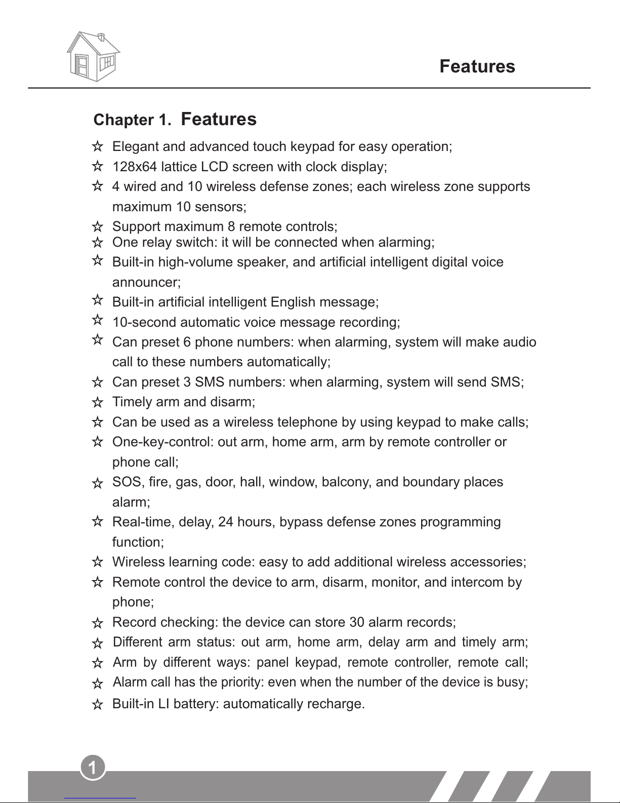
Chapter 1. Features
Page 5
System di sarmed
2
Chapter 2. Control Panel Introduction
Control Panel Introduction
2.
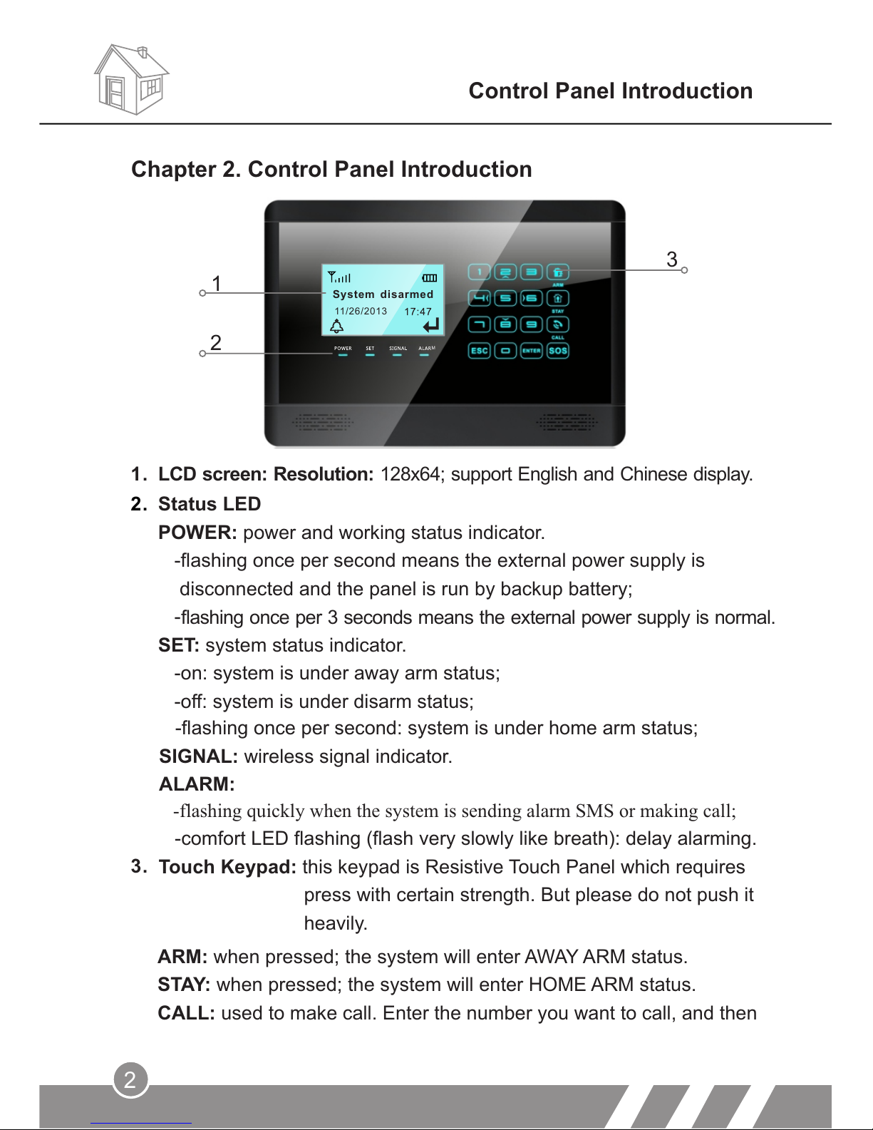
Status LED
POWER: power and working status indicator.
-flashing once per second means the external power supply is
disconnected and the panel is run by backup battery;
-
SET: system status indicator.
-on: system is under away arm status;
-off: system is under disarm status;
1.
LCD screen: Resolution: 128x64; support English and Chinese display.
-flashing once per second: system is under home arm status;
SIGNAL: wireless signal indicator.
ALARM:
ARM: when pressed; the system will enter AWAY ARM status.
STAY: when pressed; the system will enter HOME ARM status.
CALL: used to make call. Enter the number you want to call, and then
-flashing quickly when the system is sending alarm SMS or making call;
-comfort LED flashing (flash very slowly like breath): delay alarming.
Touch Keypad: this keypad is Resistive Touch Panel which requires
press with certain strength. But please do not push it
heavily.
1
2
3
flashing once per 3 seconds means the external power supply is normal.
3.
11/2 6/201 3
M
Page 6
3
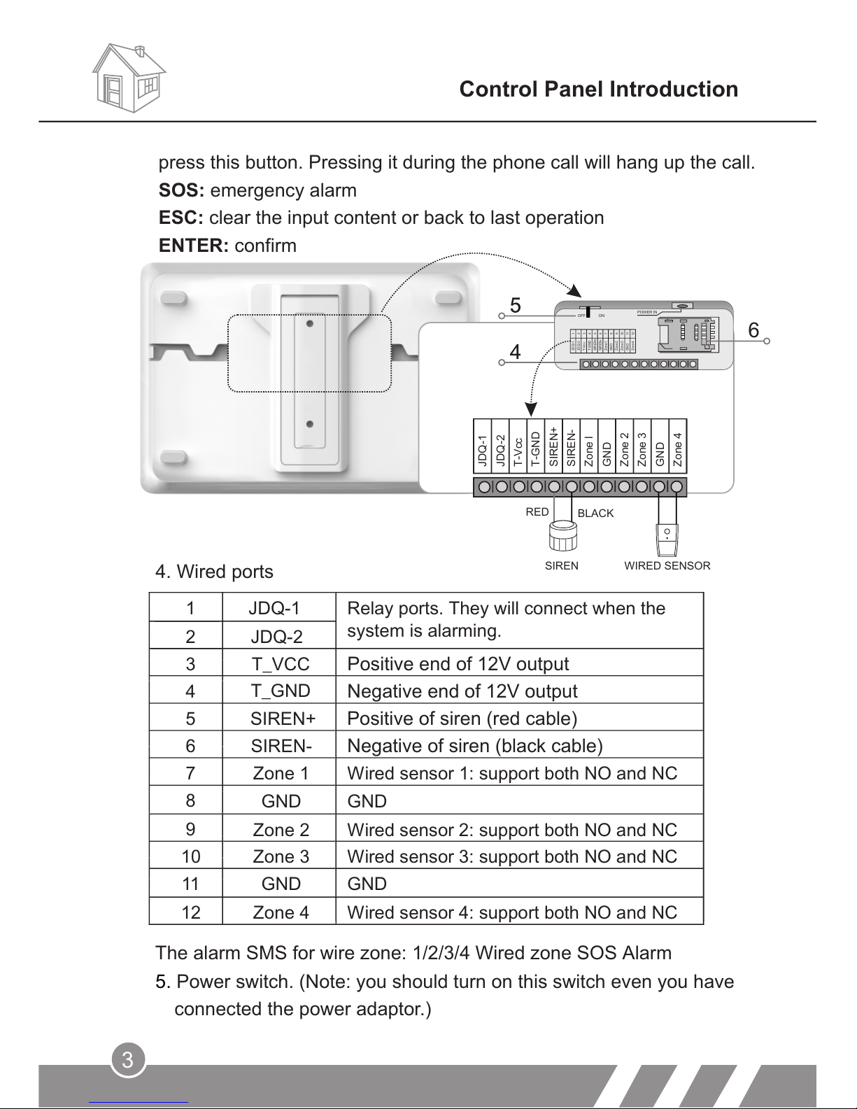
4. Wired ports
Control Panel Introduction
6
JDQ-2
T-Vcc
T-GND
SIREN+
SIREN-
Zone l
GND
Zone 2
Zone 3
GND
Zone 4
JDQ-1
RED
SIREN WIRED SENSOR
101112
JDQ-1
JDQ-2
T-Vcc
T-GND
SIREN+
SIREN-
Zone1
GND
Zone2
Zone3
GND
Zone4
123456789
OFF ON
POWER IN
press this button. Pressing it during the phone call will hang up the call.
SOS: emergency alarm
ESC: clear the input content or back to last operation
ENTER: confirm
The alarm SMS for wire zone: 1/2/3/4 Wired zone SOS Alarm
5. Power switch. (Note: you should turn on this switch even you have
connected the power adaptor.)
1
JDQ-1
Relay ports. They will connect when the
system is alarming.
2 JDQ-2
3
T_VCC Positive end of 12V output
4
Negative end of 12V output
5
SIREN+
Positive of siren (red cable)
6
SIREN-
Negative of siren (black cable)
7
8
9
10
11
GND
GND
12
T_GND
Zone 1
Wired sensor 1: support both NO and NC
GND
GND
Zone 2 Wired sensor 2: support both NO and NC
Zone 3 Wired sensor 3: support both NO and NC
Zone 4 Wired sensor 4: support both NO and NC
BLACK
Page 7
4
Initialization
Chapter 3. Initialization
Correct initiation of the main panel is important to its normal working
and lifespan.
1. Connect the wired accessories that you need.
2. Insert SIM card.
3.
Chapter 4. System Settings
All the settings have to be done in setting status. Press 2/8/4/6 to turn
up/ down/ left/ right.
1. Enter Settings
Turn on the power switch.
Enter setting status: in the state of disarm, input 6-digit password
(system default: 123123), and then press ENTER. The main panel
makes a “beep” and SET indicator lights on. The screen shows remote
controller setting.
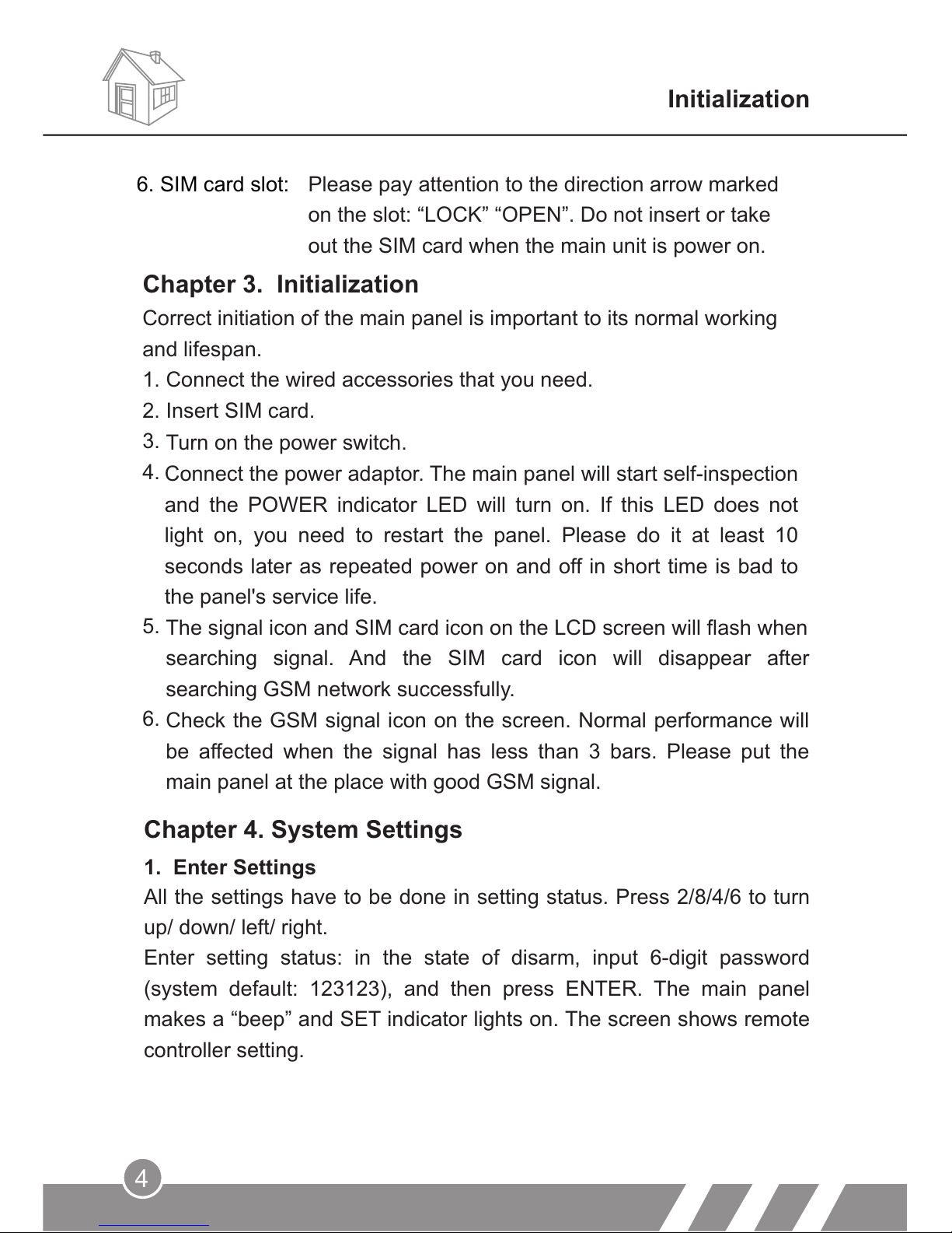
Please pay attention to the direction arrow marked
on the slot: “LOCK” “OPEN”. Do not insert or take
out the SIM card when the main unit is power on.
6. SIM card slot:
Connect the power adaptor. The main panel will start self-inspection
and the POWER indicator LED will turn on. If this LED does not
light on, you need to restart the panel. Please do it at least 10
seconds later as repeated power on and off in short time is bad to
the panel's service life.
4.
5.
The signal icon and SIM card icon on the LCD screen will flash when
searching signal. And the SIM card icon will disappear after
searching GSM network successfully.
6.
Check the GSM signal icon on the screen. Normal performance will
be affected when the signal has less than 3 bars. Please put the
main panel at the place with good GSM signal.
Page 8
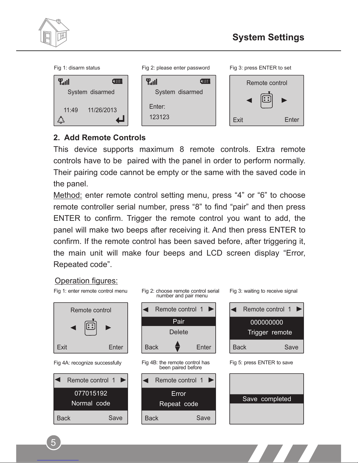
2. Add Remote Controls
This device supports maximum 8 remote controls. Extra remote
controls have to be paired with the panel in order to perform normally.
Their pairing code cannot be empty or the same with the saved code in
the panel.
Method: enter remote control setting menu, press “4” or “6” to choose
remote controller serial number, press “8” to find “pair” and then press
ENTER to confirm. Trigger the remote control you want to add, the
panel will make two beeps after receiving it. And then press ENTER to
confirm. If the remote control has been saved before, after triggering it,
the main unit will make four beeps and LCD screen display “Error,
Repeated code”.
Fig 1: enter remote control menu Fig 2: choose remote control serial
number and pair menu
Fig 3: waiting to receive signal
Fig 4A: recognize successfully
Fig 4B: the remote control has
been paired before
Fig 5: press ENTER to save
Remote control
Exit
Enter
Operation figures:
Remote control 1
Back
Enter
Pair
Delete
Remote control 1
Back
Save
000000000
Trigger remote
Remote control 1
Back
Save
077015192
Normal code
Remote control 1
Back
Save
Error
Repeat code
System Settings
Fig 1: disarm status
System disarmed
123123
Enter:
System disarmed
11:49 11/26/2013
Remote control
Exit
Enter
Fig 2: please enter password Fig 3: press ENTER to set
5
Save completed
Page 9
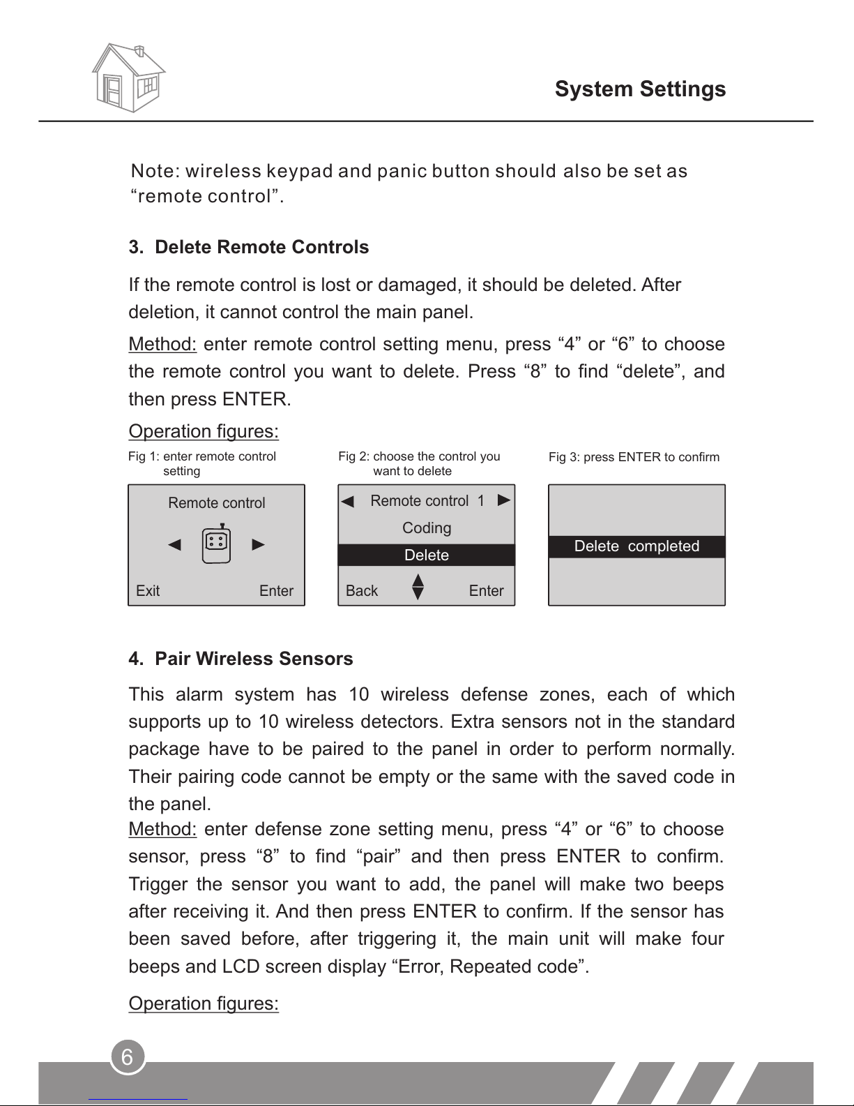
3. Delete Remote Controls
If the remote control is lost or damaged, it should be deleted. After
deletion, it cannot control the main panel.
6
System Settings
Fig 1: enter remote control
setting
Fig 2: choose the control you
want to delete
Fig 3: press ENTER to confirm
Method: enter remote control setting menu, press “4” or “6” to choose
the remote control you want to delete. Press “8” to find “delete”, and
then press ENTER.
Operation figures:
Remote control 1
Back
Enter
Coding
Delete
Remote control
Exit
Enter
This alarm system has 10 wireless defense zones, each of which
supports up to 10 wireless detectors. Extra sensors not in the standard
package have to be paired to the panel in order to perform normally.
Their pairing code cannot be empty or the same with the saved code in
the panel.
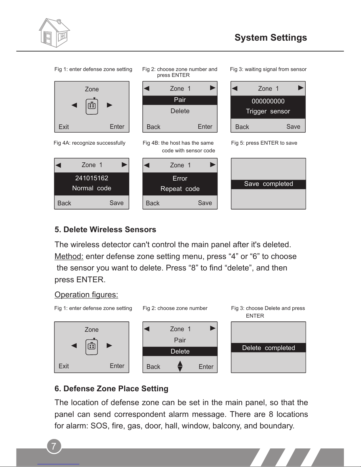
Method: enter defense zone setting menu, press “4” or “6” to choose
sensor, press “8” to find “pair” and then press ENTER to confirm.
Trigger the sensor you want to add, the panel will make two beeps
after receiving it. And then press ENTER to confirm. If the sensor has
been saved before, after triggering it, the main unit will make four
beeps and LCD screen display “Error, Repeated code”.
Operation figures:
4. Pair Wireless Sensors
Note: wireless keypad and panic button should also be set as
“remote control”.
Delete completed
Page 10
7
System Settings
Fig 4A: recognize successfully
Fig 4B: the host has the same
code with sensor code
Fig 5: press ENTER to save
Back
Save
Error
Repeat code
Zone 1
Back
Save
241015162
Normal code
Zone 1
5. Delete Wireless Sensors
The wireless detector can't control the main panel after it's deleted.
Method: enter defense zone setting menu, press “4” or “6” to choose
the sensor you want to delete. Press “8” to find “delete”, and then
press ENTER.
6. Defense Zone Place Setting
The location of defense zone can be set in the main panel, so that the
panel can send correspondent alarm message. There are 8 locations
for alarm: SOS, fire, gas, door, hall, window, balcony, and boundary.
Operation figures:
Pair
Delete
Zone 1
Back
Enter
Zone
Enter
Exit
Fig 1: enter defense zone setting
Fig 2: choose zone number Fig 3: choose Delete and press
ENTER
Back
Save
Exit
Enter
Enter
Exit
Fig 1: enter defense zone setting
Fig 2: choose zone number and
press ENTER
Fig 3: waiting signal from sensor
000000000
Trigger sensor
Zone 1Zone 1
Pair
Delete
Zone
Enter
Exit
Enter
Back
Delete completed
Save completed
Save
Back
Page 11
8
System Settings
Operation figures:
Back
Enter
Place: Fire
Armed: Enable
Zone 1
Back
Enter
Place: GAS
Armed: Enable
Zone 1
Zone
Enter
Exit
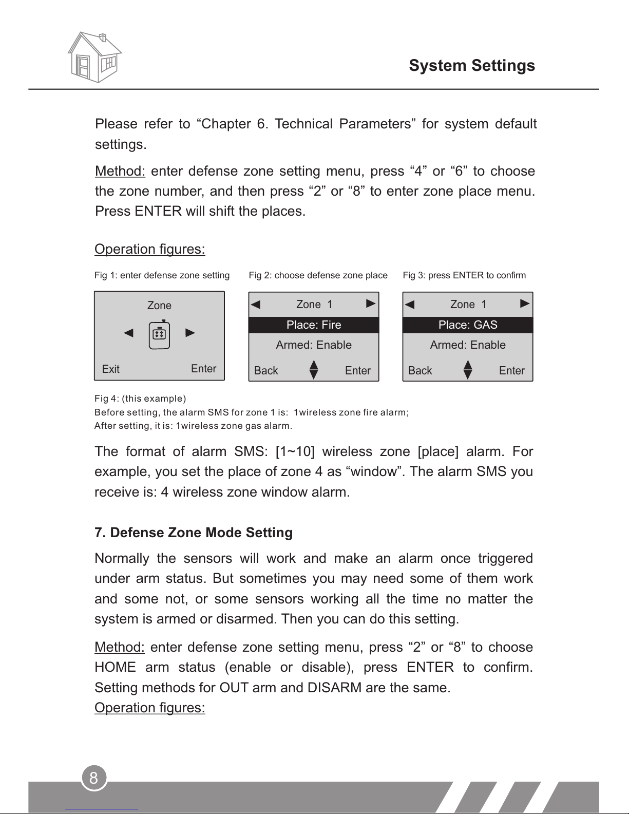
Fig 1: enter defense zone setting Fig 2: choose defense zone place Fig 3: press ENTER to confirm
Fig 4: (this example)
Before setting, the alarm SMS for zone 1 is: 1wireless zone fire alarm;
After setting, it is: 1wireless zone gas alarm.
The format of alarm SMS: [1~10] wireless zone [place] alarm. For
example, you set the place of zone 4 as “window”. The alarm SMS you
receive is: 4 wireless zone window alarm.
7. Defense Zone Mode Setting
Normally the sensors will work and make an alarm once triggered
under arm status. But sometimes you may need some of them work
and some not, or some sensors working all the time no matter the
system is armed or disarmed. Then you can do this setting.
Method: enter defense zone setting menu, press “2” or “8” to choose
HOME arm status (enable or disable), press ENTER to confirm.
Setting methods for OUT arm and DISARM are the same.
Operation figures:
Please refer to “Chapter 6. Technical Parameters” for system default
settings.
Method: enter defense zone setting menu, press “4” or “6” to choose
the zone number, and then press “2” or “8” to enter zone place menu.
Press ENTER will shift the places.
Page 12
Back
Enter
Zone 1
Back
Enter
Siren:1 min
Delay:Disable
Zone 1
19
System Settings
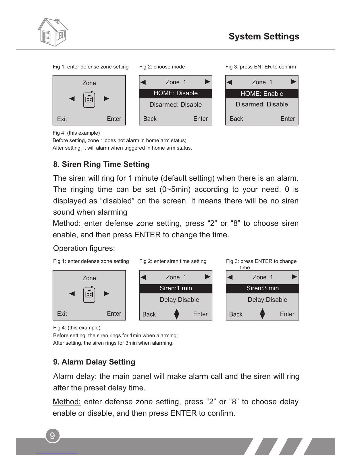
8. Siren Ring Time Setting
The siren will ring for 1 minute (default setting) when there is an alarm.
The ringing time can be set (0~5min) according to your need. 0 is
displayed as “disabled” on the screen. It means there will be no siren
sound when alarming
Fig 1: enter defense zone setting
Fig 2: enter siren time setting Fig 3: press ENTER to change
Fig 4: (this example)
Before setting, the siren rings for 1min when alarming;
After setting, the siren rings for 3min when alarming.
9. Alarm Delay Setting
Alarm delay: the main panel will make alarm call and the siren will ring
after the preset delay time.
Zone
Enter
Exit
Method: enter defense zone setting, press “2” or “8” to choose siren
enable, and then press ENTER to change the time.
Method: enter defense zone setting, press “2” or “8” to choose delay
enable or disable, and then press ENTER to confirm.
Operation figures:
Back
Enter
Back
Enter
Enter
Exit
Fig 4: (this example)
Before setting, zone 1 does not alarm in home arm status;
After setting, it will alarm when triggered in home arm status.
Fig 1: enter defense zone setting Fig 2: choose mode Fig 3: press ENTER to confirm
HOME: Disable
Disarmed: Disable
Zone 1 Zone 1
Disarmed: Disable
HOME: Enable
Zone
Enter
Exit
Back Enter Back Enter
Siren:3 min
Delay:Disable
time
Page 13
10
System Settings
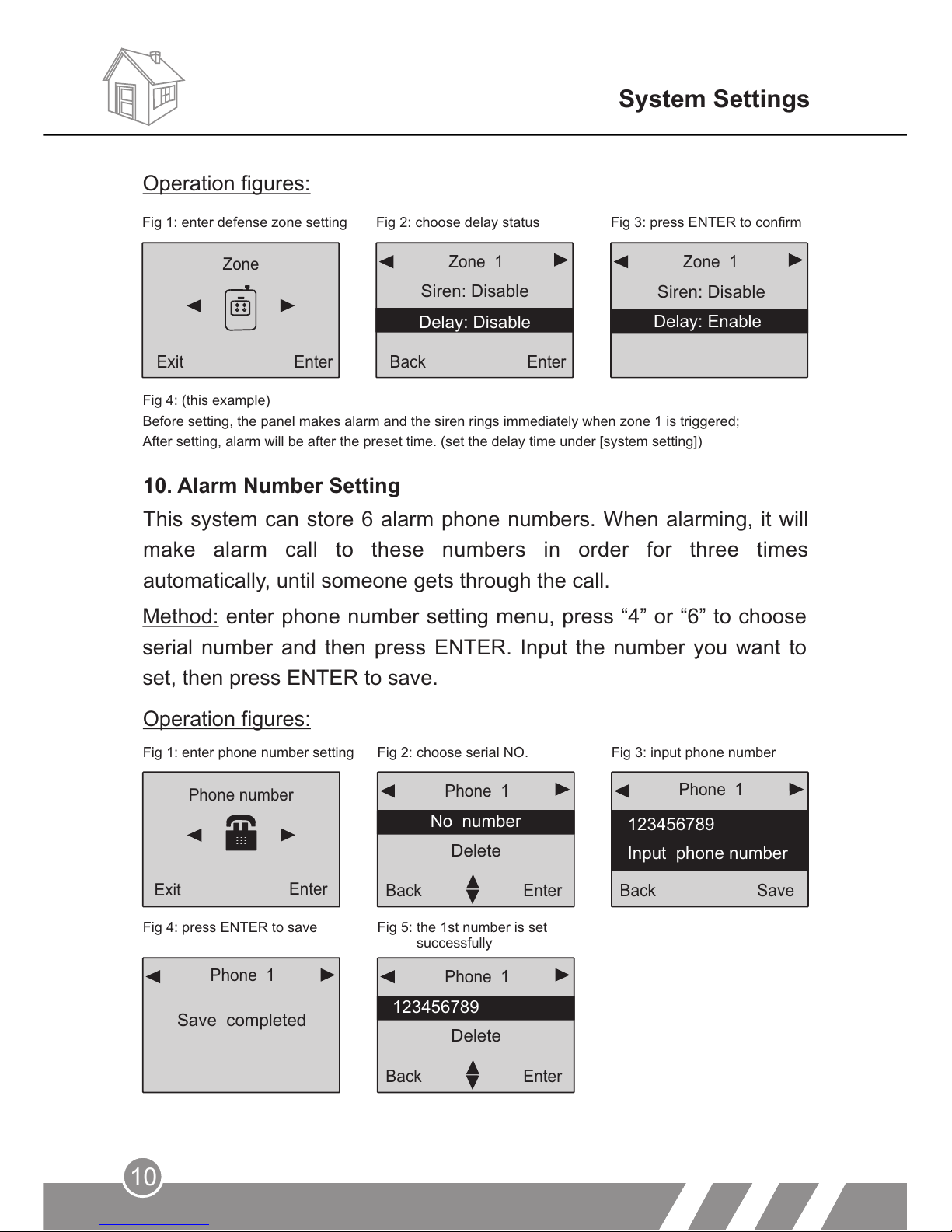
10. Alarm Number Setting
This system can store 6 alarm phone numbers. When alarming, it will
make alarm call to these numbers in order for three times
automatically, until someone gets through the call.
Method: enter phone number setting menu, press “4” or “6” to choose
serial number and then press ENTER. Input the number you want to
set, then press ENTER to save.
Operation figures:
Fig 1: enter phone number setting
Fig 2: choose serial NO.
Fig 3: input phone number
Fig 4: press ENTER to save
Fig 5: the 1st number is set
successfully
Phone 1
Back
Enter
No number
Delete
Back
Save
123456789
Input phone number
Phone 1
Phone 1
Save completed
Phone number
Exit
Enter
Phone 1
Back
123456789
Delete
Enter
Back
Enter
Back
Enter
Enter
Exit
Zone 1Zone 1
Fig 1: enter defense zone setting
Fig 2: choose delay status
Fig 3: press ENTER to confirm
Zone
Operation figures:
Siren: Disable
Siren: Disable
Delay: Enable
Delay: Disable
Fig 4: (this example)
Before setting, the panel makes alarm and the siren rings immediately when zone 1 is triggered;
After setting, alarm will be after the preset time. (set the delay time under [system setting])
Exit
Enter Back Enter
Page 14
11
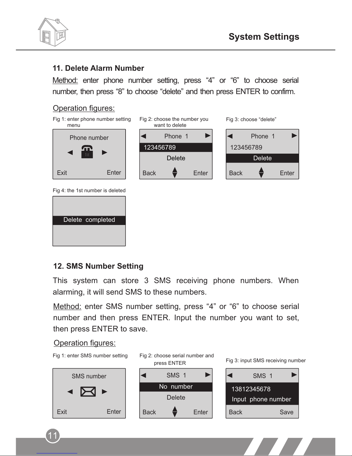
Fig 4: the 1st number is deleted
12. SMS Number Setting
This system can store 3 SMS receiving phone numbers. When
alarming, it will send SMS to these numbers.
Method: enter SMS number setting, press “4” or “6” to choose serial
number and then press ENTER. Input the number you want to set,
then press ENTER to save.
Operation figures:
Fig 1: enter SMS number setting
Fig 2: choose serial number and
press ENTER
Fig 3: input SMS receiving number
SMS 1
Back
Enter
No number
Delete
Back
13812345678
Input phone number
SMS 1
Save
SMS number
Exit
Enter
System Settings
11. Delete Alarm Number
Method: enter phone number setting, press “4” or “6” to choose serial
number, then press “8” to choose “delete” and then press ENTER to confirm.
Phone number
Exit
Enter
Operation figures:
Fig 1: enter phone number setting
menu
Fig 2: choose the number you
want to delete
Fig 3: choose “delete”
Phone 1
123456789
Delete
Back
Enter
Phone 1
Delete
Back
Enter
123456789
Delete completed
Page 15
Back
Enter
13812345678
Delete
SMS 1
Back
13812345678
Delete
SMS 1
Enter
12
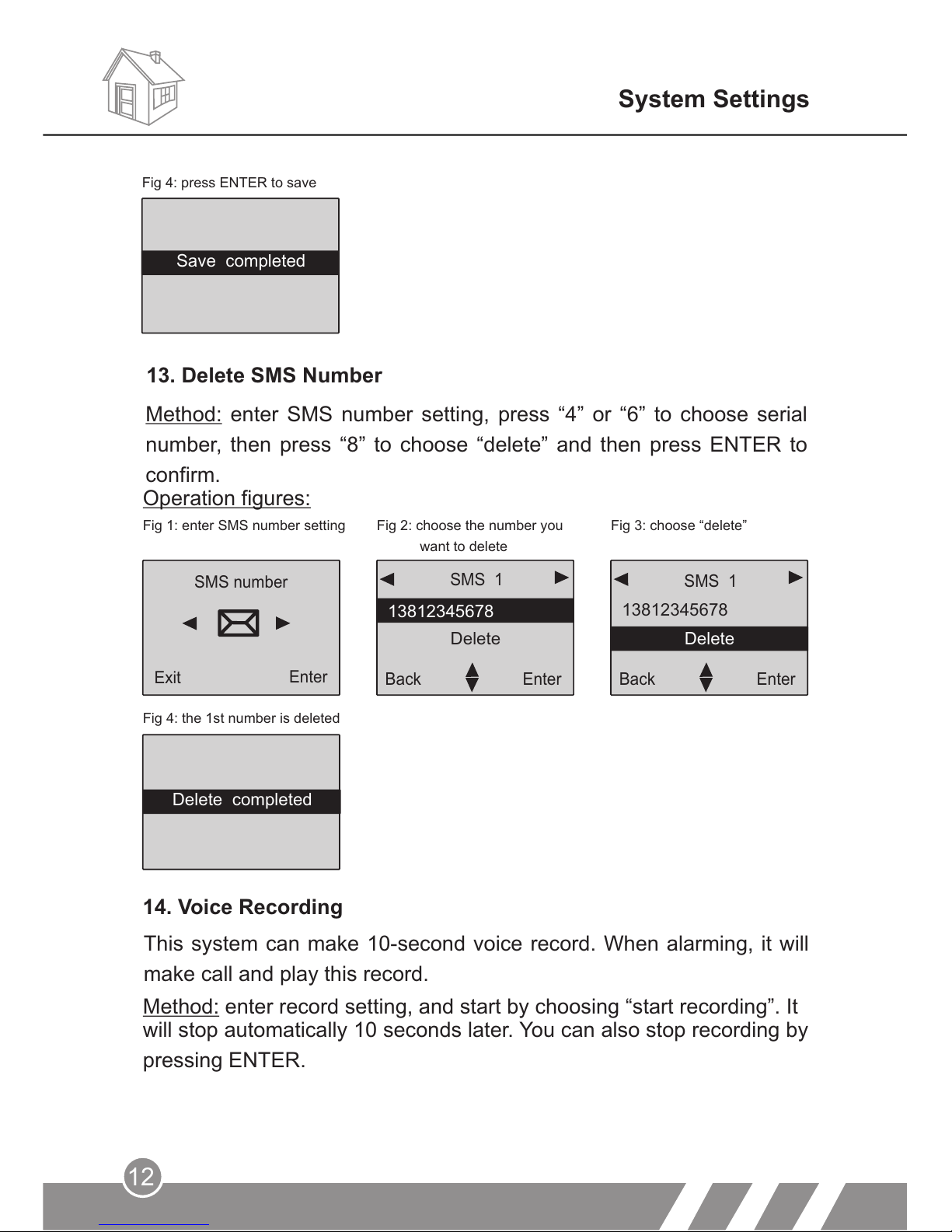
Operation figures:
Fig 1: enter SMS number setting
Fig 2: choose the number you
want to delete
Fig 3: choose “delete”
Fig 4: the 1st number is deleted
SMS number
Exit
Enter
System Settings
14. Voice Recording
This system can make 10-second voice record. When alarming, it will
make call and play this record.
Method: enter record setting, and start by choosing “start recording”. It
will stop automatically 10 seconds later. You can also stop recording by
pressing ENTER.
Fig 4: press ENTER to save
13. Delete SMS Number
Method: enter SMS number setting, press “4” or “6” to choose serial
number, then press “8” to choose “delete” and then press ENTER to
confirm.
Save completed
Delete completed
Page 16
13
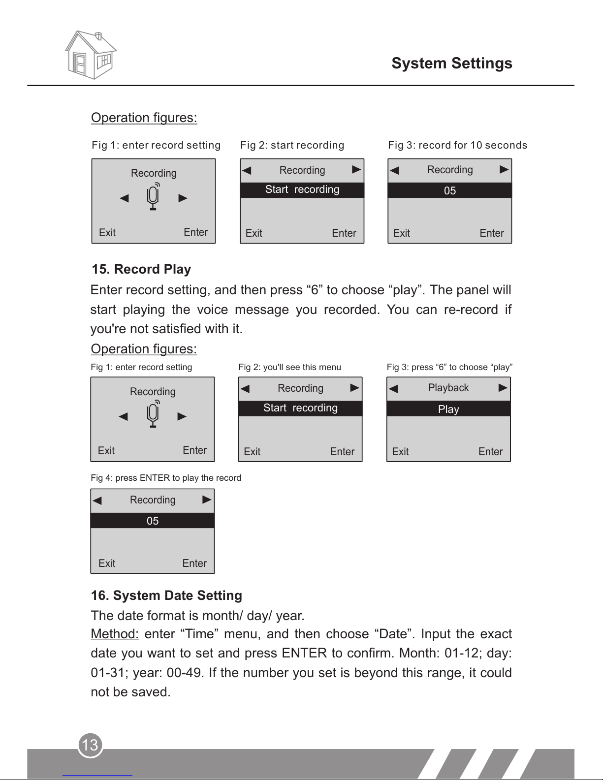
Operation figures:
Fig 1: enter record setting Fig 2: you'll see this menu
Fig 3: press “6” to choose “play”
Fig 4: press ENTER to play the record
16. System Date Setting
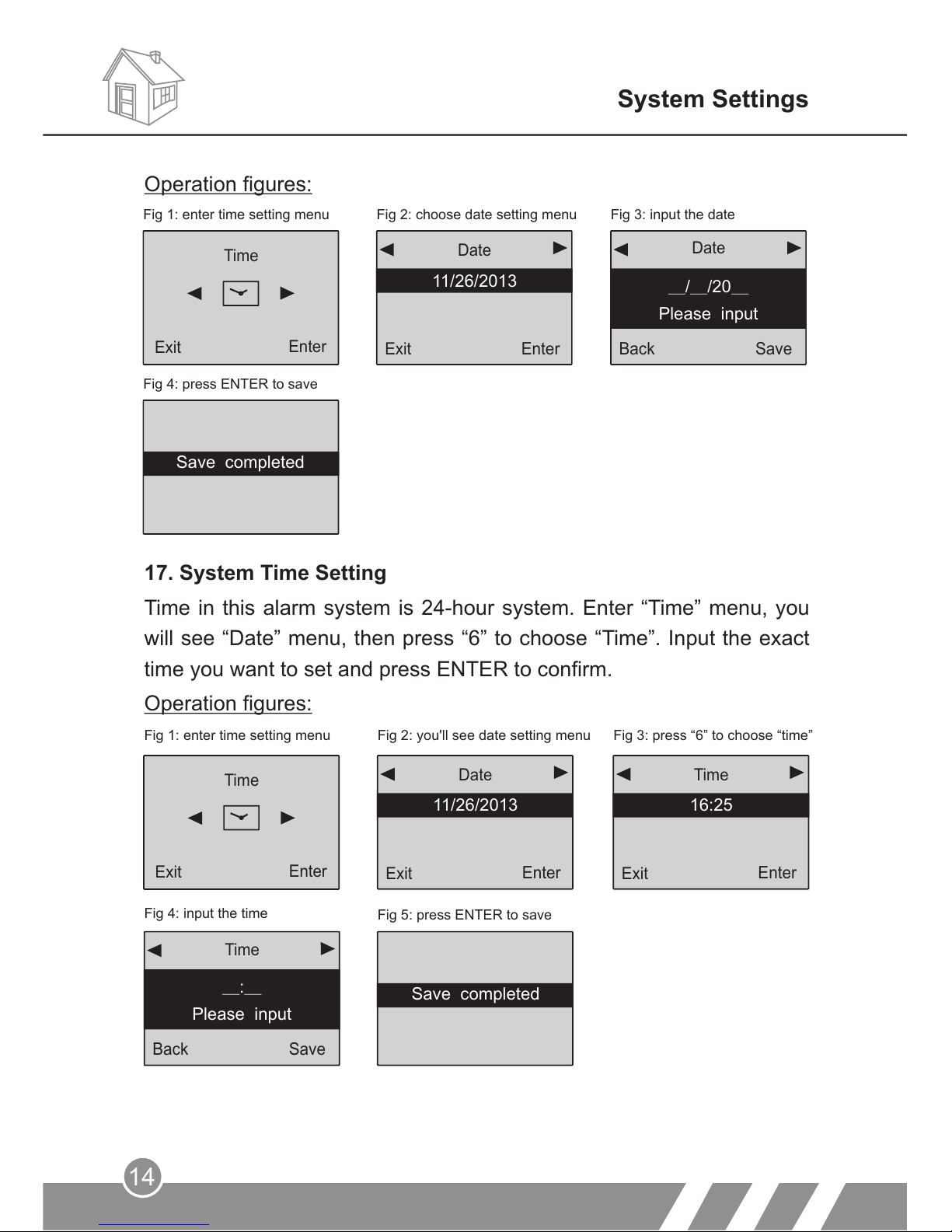
Method: enter “Time” menu, and then choose “Date”. Input the exact
date you want to set and press ENTER to confirm. Month: 01-12; day:
01-31; year: 00-49. If the number you set is beyond this range, it could
not be saved.
Recording
Exit
Enter
Exit
Enter
Start recording
Recording
Exit
Play
Playback
Enter
Exit
05
Recording
Enter
The date format is month/ day/ year.
System Settings
Enter record setting, and then press “6” to choose “play”. The panel will
start playing the voice message you recorded. You can re-record if
you're not satisfied with it.
Fig 1: enter record setting Fig 2: start recording Fig 3: record for 10 seconds
Recording
Exit
Enter
Exit
Enter
Start recording
Recording
Exit
05
Recording
Enter
15. Record Play
Operation figures:
Page 17
Exit
Enter
Date
Exit
Enter
Time
16:25
Back
Save
_:_
Please input
Time
14
17. System Time Setting
Time in this alarm system is 24-hour system. Enter “Time” menu, you
will see “Date” menu, then press “6” to choose “Time”. Input the exact
time you want to set and press ENTER to confirm.
Operation figures:
Fig 1: enter time setting menu Fig 2: you'll see date setting menu Fig 3: press “6” to choose “time”
Fig 4: input the time
Fig 5: press ENTER to save
Enter
Time
Exit
System Settings
Save completed
Date
Back
Save
_ _/ /20_
Please input
Date
Exit
Enter
11/26 2013/
Date
Enter
Time
Exit
Fig 1: enter time setting menu Fig 2: choose date setting menu Fig 3: input the date
Fig 4: press ENTER to save
Operation figures:
Save completed
11/26 2013/
Save completed
Page 18
15
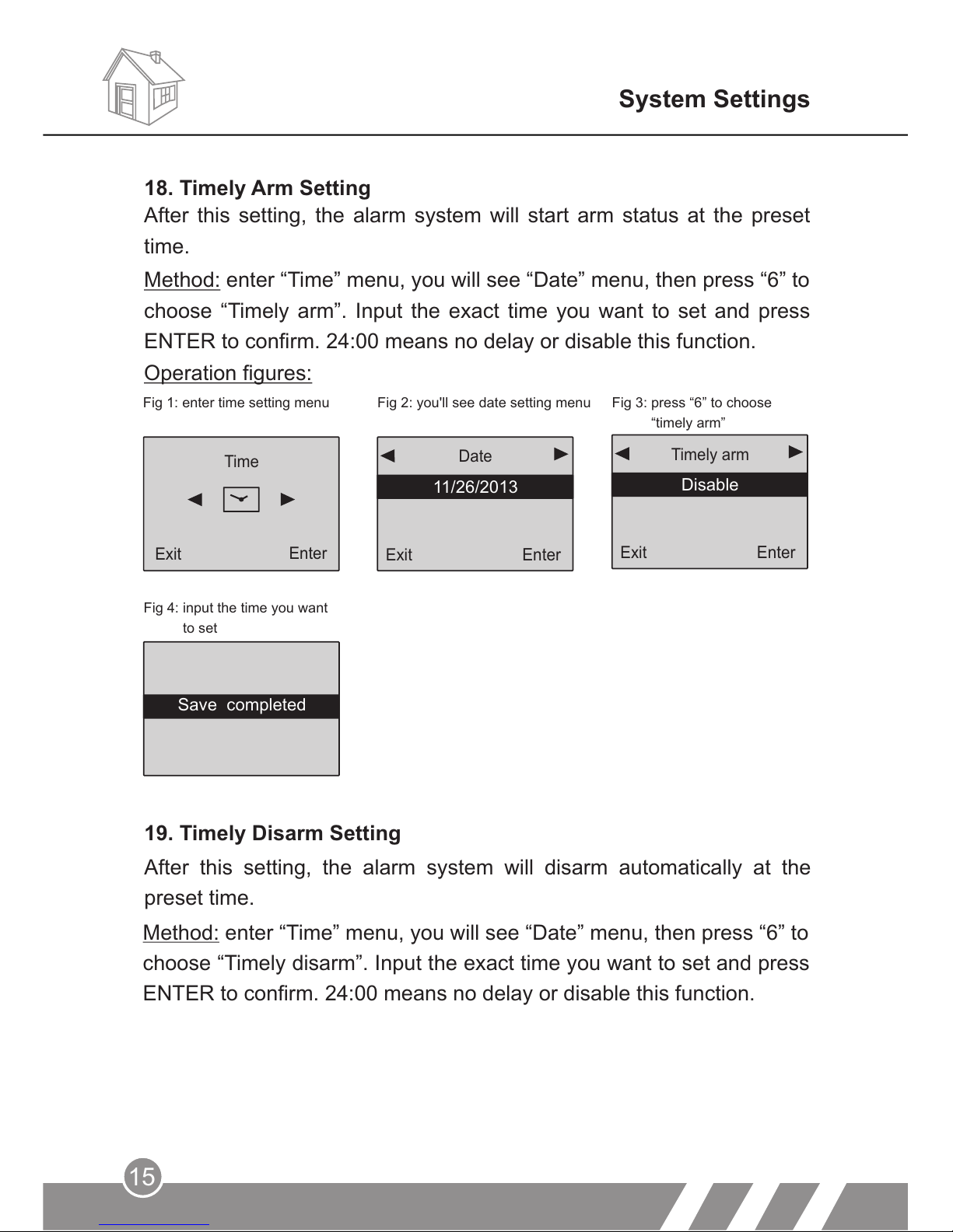
Fig 4: input the time you want
to set
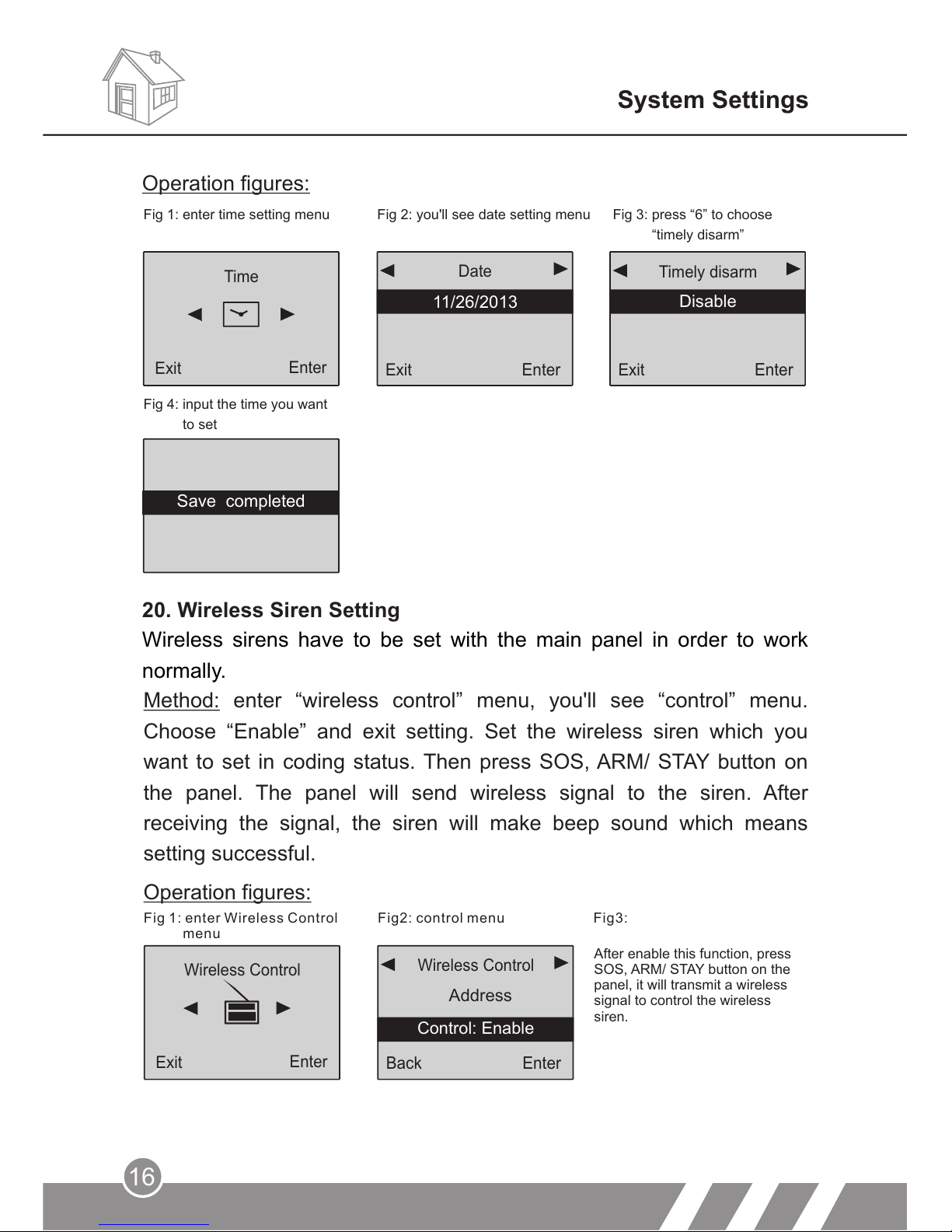
19. Timely Disarm Setting
After this setting, the alarm system will disarm automatically at the
preset time.
System Settings
Method: enter “Time” menu, you will see “Date” menu, then press “6” to
choose “Timely disarm”. Input the exact time you want to set and press
ENTER to confirm. 24:00 means no delay or disable this function.
Exit
Enter
11/26/2013
Date
Exit
Enter
Timely arm
Disable
Operation figures:
Fig 1: enter time setting menu Fig 2: you'll see date setting menu
Fig 3: press “6” to choose
“timely arm”
Enter
Time
Exit
After this setting, the alarm system will start arm status at the preset
time.
Method: enter “Time” menu, you will see “Date” menu, then press “6” to
choose “Timely arm”. Input the exact time you want to set and press
ENTER to confirm. 24:00 means no delay or disable this function.
18. Timely Arm Setting
Save completed
Page 19
System Settings
Exit
Enter
Timely disarm
Disable
Exit
Enter
11/26/2013
Date
Enter
Time
Exit
Fig 1: enter time setting menu Fig 2: you'll see date setting menu
Fig 3: press “6” to choose
“timely disarm”
Fig 4: input the time you want
to set
20. Wireless Siren Setting
Wireless sirens have to be set with the main panel in order to work
normally.
Operation figures:
Method: enter “wireless control” menu, you'll see “control” menu.
Choose “Enable” and exit setting. Set the wireless siren which you
want to set in coding status. Then press SOS, ARM/ STAY button on
the panel. The panel will send wireless signal to the siren. After
receiving the signal, the siren will make beep sound which means
setting successful.
Operation figures:
Fig 1: enter Wireless Control
menu
Fig2: control menu
Back
Enter
Address
Wireless Control
Wireless Control
Enter
Exit
16
Control: Enable
Save completed
After enable this function, press
SOS, ARM/ STAY button on the
panel, it will transmit a wireless
signal to control the wireless
siren.
Fig3:
Page 20
17
System Settings
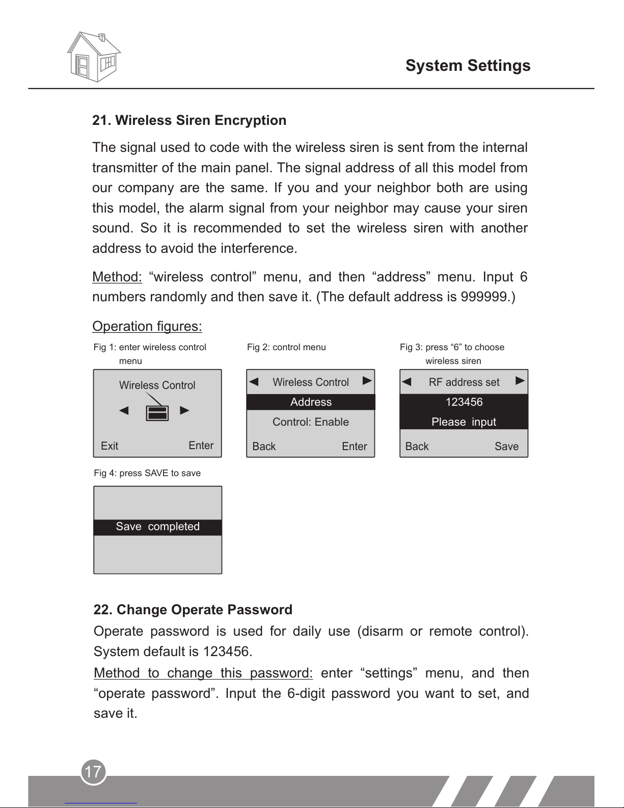
Method: “wireless control” menu, and then “address” menu. Input 6
numbers randomly and then save it. (The default address is 999999.)
Operation figures:
21. Wireless Siren Encryption
The signal used to code with the wireless siren is sent from the internal
transmitter of the main panel. The signal address of all this model from
our company are the same. If you and your neighbor both are using
this model, the alarm signal from your neighbor may cause your siren
sound. So it is recommended to set the wireless siren with another
address to avoid the interference.
Fig 1: enter wireless control
menu
Fig 2: control menu
Fig 3: press “6” to choose
wireless siren
Fig 4: press SAVE to save
Wireless Control
Enter
Exit
Back
Enter
Address
Wireless Control
Back
Save
123456
RF address set
Please input
Operate password is used for daily use (disarm or remote control).
System default is 123456.
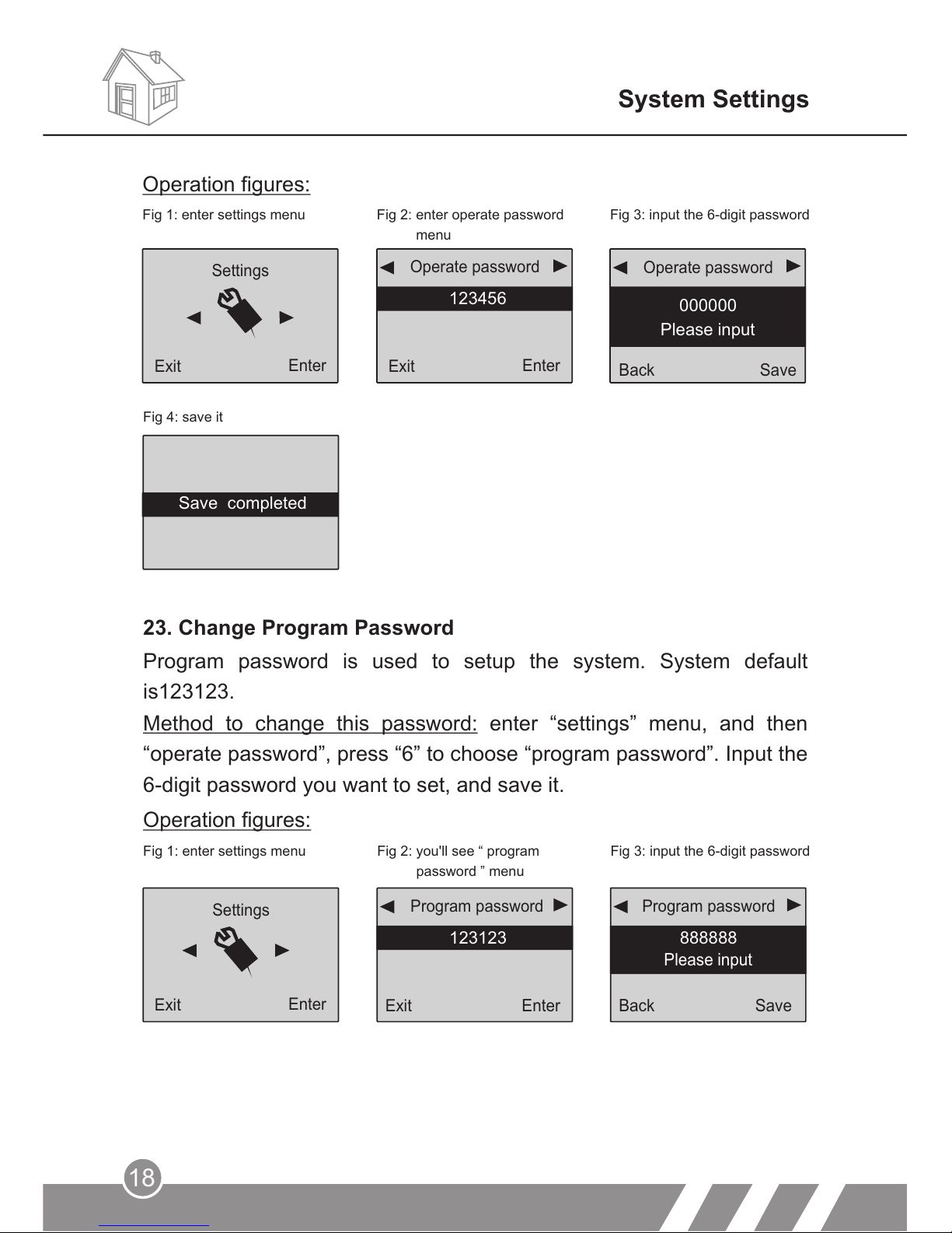
22. Change Operate Password
Method to change this password: enter “settings” menu, and then
“operate password”. Input the 6-digit password you want to set, and
save it.
Control: Enable
Save completed
Page 21
18
23. Change Program Password
Program password is used to setup the system. System default
is123123.
Fig 1: enter settings menu Fig 2: you'll see “
password ” menu
program
Fig 3: input the 6-digit password
Method to change this password: enter “settings” menu, and then
“operate password”, press “6” to choose “program password”. Input the
6-digit password you want to set, and save it.
Operation figures:
Back
Save
888888
Program password
Exit
Enter
123123
Program password
Settings
Exit
Enter
System Settings
Fig 4: save it
Back
Save
4545
Please input
Back
Enter
Exit
Enter
Operation figures:
Fig 2: enter operate password
menu
Fig 1: enter settings menu Fig 3: input the 6-digit password
Operate password
Operate password
Settings
123456
000000
Please input
Back Save
Please input
Exit
Enter
Exit
Enter
Save completed
Page 22
Settings
Exit
Enter
Exit
Enter
123456
Operate password
Exit
Enter
40
Delay arm
Back
Save
08
Please input
Delay arm
19
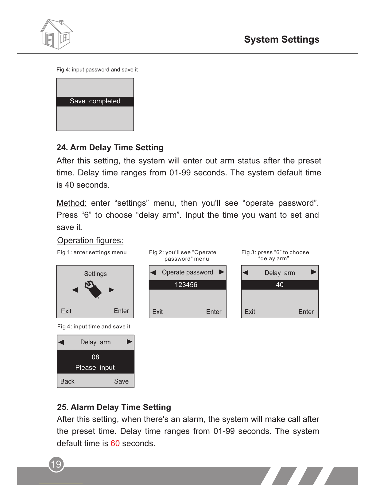
Method: enter “settings” menu, then you'll see “operate password”.
Press “6” to choose “delay arm”. Input the time you want to set and
save it.
Fig 1: enter settings menu
Fig 2: you'll see “Operate
password” menu
Fig 3: press “6” to choose
“delay arm”
Fig 4: input time and save it
Operation figures:
25. Alarm Delay Time Setting
After this setting, when there's an alarm, the system will make call after
the preset time. Delay time ranges from 01-99 seconds. The system
default time is seconds.60
System Settings
After this setting, the system will enter out arm status after the preset
time. Delay time ranges from 01-99 seconds. The system default time
is 40 seconds.
Fig 4: input password and save it
24. Arm Delay Time Setting
Save completed
Page 23
Exit
Enter
Enable
Voice prompt
Exit
Enter
123456
Operate password
Settings
Exit
Enter
20
Back
Save
15
Please input
Delay alarm
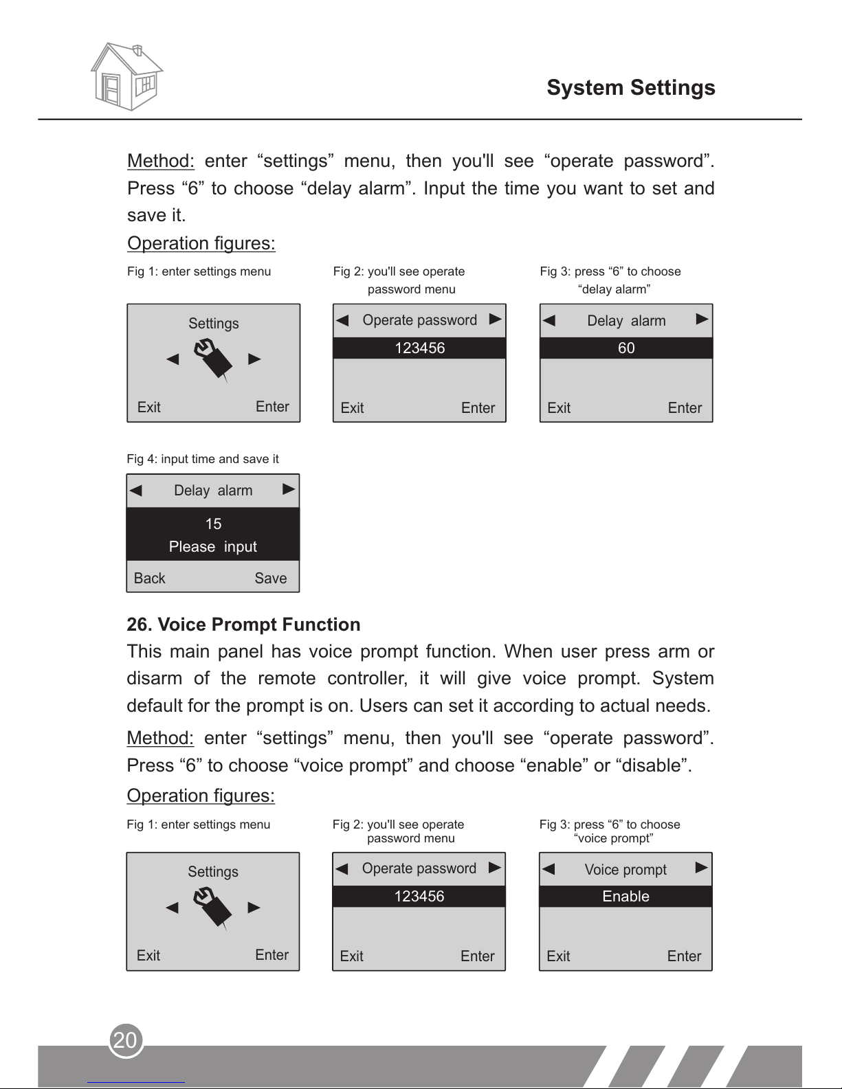
Fig 4: input time and save it
26. Voice Prompt Function
This main panel has voice prompt function. When user press arm or
disarm of the remote controller, it will give voice prompt. System
default for the prompt is on. Users can set it according to actual needs.
Fig 1: enter settings menu Fig 2: you'll see operate
password menu
Fig 3: press “6” to choose
“voice prompt”
Method: enter “settings” menu, then you'll see “operate password”.
Press “6” to choose “voice prompt” and choose “enable” or “disable”.
Operation figures:
System Settings
Exit
Enter
60
Delay alarm
Exit
Enter
123456
Operate password
Settings
Exit
Enter
Fig 1: enter settings menu Fig 2: you'll see operate
password menu
Fig 3: press “6” to choose
“delay alarm”
Operation figures:
Method: enter “settings” menu, then you'll see “operate password”.
Press “6” to choose “delay alarm”. Input the time you want to set and
save it.
Page 24
21
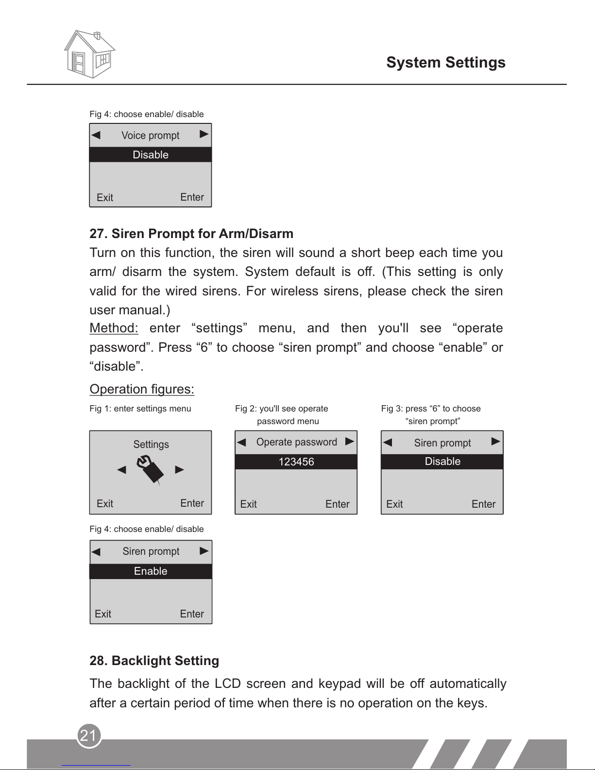
Fig 1: enter settings menu Fig 2: you'll see operate
password menu
Fig 3: press “6” to choose
“siren prompt”
Fig 4: choose enable/ disable
Settings
Exit
Enter
Exit
Enter
123456
Operate password
Exit
Enter
Siren prompt
Disable
Enable
Exit
Enter
Siren prompt
Enable
Operation figures:
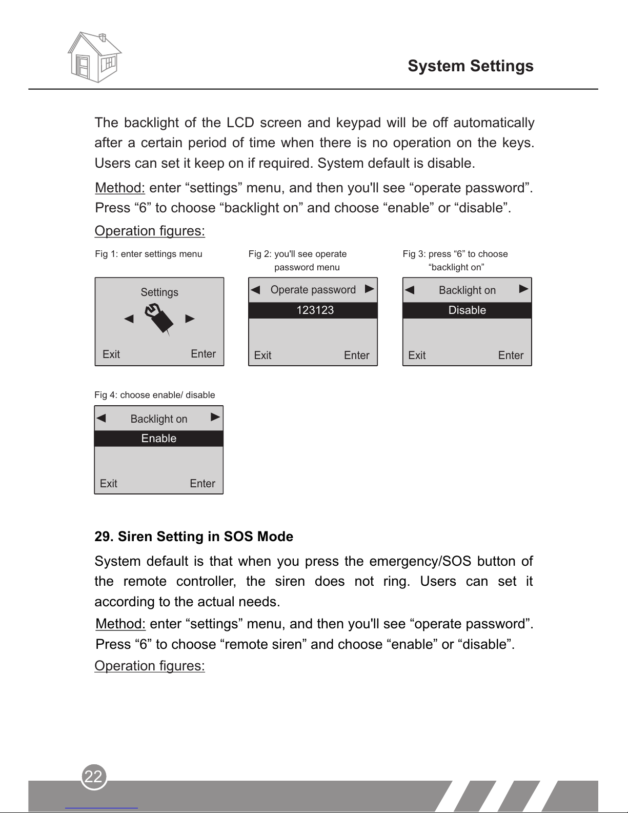
28. Backlight Setting
The backlight of the LCD screen and keypad will be off automatically
after a certain period of time when there is no operation on the keys.
System Settings
Method: enter “settings” menu, and then you'll see “operate
password”. Press “6” to choose “siren prompt” and choose “enable” or
“disable”.
27. Siren Prompt for Arm/Disarm
Turn on this function, the siren will sound a short beep each time you
arm/ disarm the system. System default is off. (This setting is only
valid for the wired sirens. For wireless sirens, please check the siren
user manual.)
Back
Enter
Voice prompt
Fig 4: choose enable/ disable
Disable
Exit
Enter
Page 25
22
Fig 4: choose enable/ disable
Enable
Exit
Enter
Backlight on
Enable
29. Siren Setting in SOS Mode
System default is that when you press the emergency/SOS button of
the remote controller, the siren does not ring. Users can set it
according to the actual needs.
Method: enter “settings” menu, and then you'll see “operate password”.
Press “6” to choose “remote siren” and choose “enable” or “disable”.
Operation figures:
System Settings
Fig 1: enter settings menu Fig 2: you'll see operate
password menu
Fig 3: press “6” to choose
“backlight on”
Operation figures:
Exit
Enter
Backlight on
Disable
Exit
Enter
123123
Operate password
Settings
Enter
Exit
The backlight of the LCD screen and keypad will be off automatically
after a certain period of time when there is no operation on the keys.
Users can set it keep on if required. System default is disable.
Method: enter “settings” menu, and then you'll see “operate password”.
Press “6” to choose “backlight on” and choose “enable” or “disable”.
Page 26
23
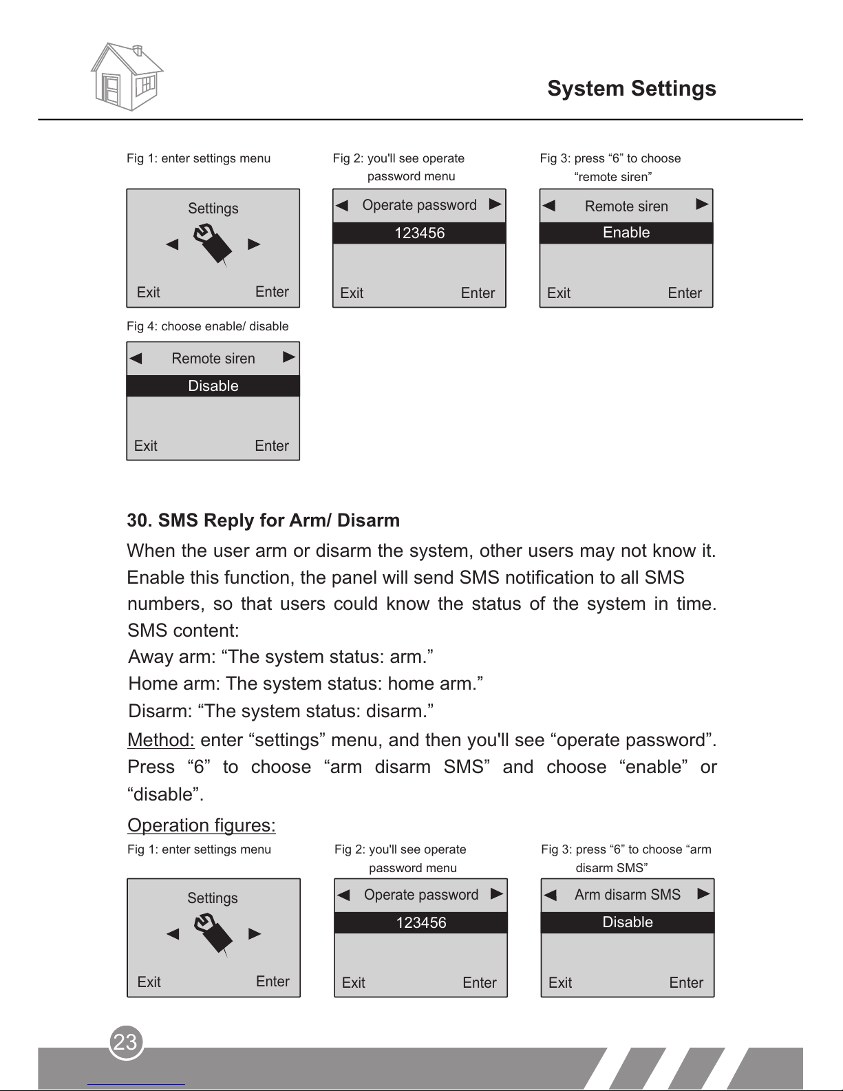
Method: enter “settings” menu, and then you'll see “operate password”.
Press “6” to choose “arm disarm SMS” and choose “enable” or
“disable”.
Operation figures:
Fig 1: enter settings menu Fig 2: you'll see operate
password menu
Fig 3: press “6” to choose “arm
disarm SMS”
Exit
Enter
123456
Operate password
Exit
Enter
Arm disarm SMS
Disable
Settings
Exit
Enter
System Settings
numbers, so that users could know the status of the system in time.
SMS content:
Enable
Exit
Enter
Disable
Remote siren
30. SMS Reply for Arm/ Disarm
When the user arm or disarm the system, other users may not know it.
Enable this function, the panel will send SMS notification to all SMS
Exit
Enter
Remote siren
Enable
Exit
Enter
123456
Operate password
Settings
Exit
Enter
Fig 1: enter settings menu Fig 2: you'll see operate
password menu
Fig 3: press “6” to choose
“remote siren”
Fig 4: choose enable/ disable
Away arm: “The system status: arm.”
Home arm: The system status: home arm.”
Disarm: “The system status: disarm.”
Page 27
24
Send SMS
AC Power ON/ OFF
Fig 4: press “ENTER” to choose
“Send SMS”
System Settings
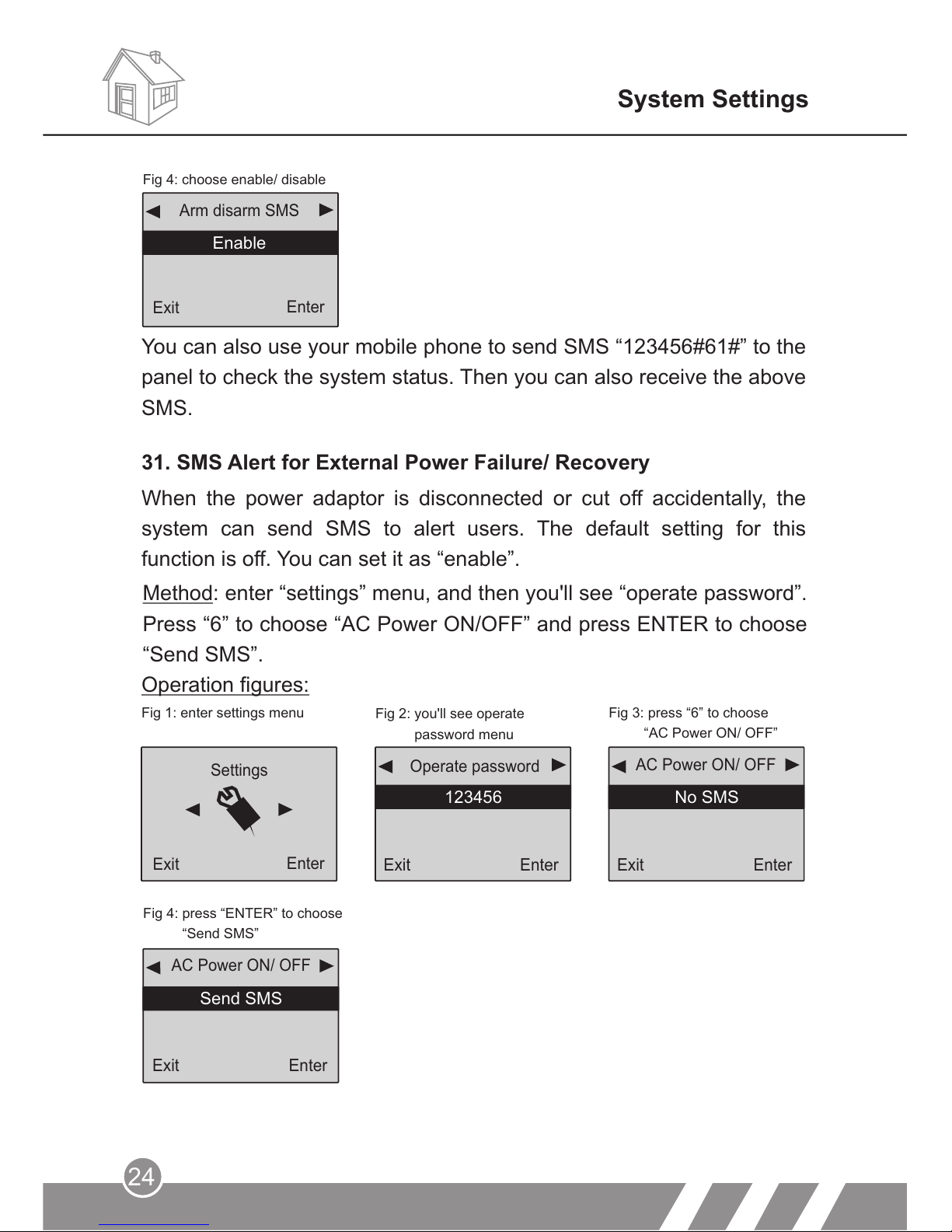
31. SMS Alert for External Power Failure/ Recovery
Back
Enter
Method: enter “settings” menu, and then you'll see “operate password”.
Press “6” to choose “AC Power ON/OFF” and press ENTER to choose
“Send SMS”.
Operation figures:
Exit
Enter
AC Power ON/ OFF
No SMS
Exit
Enter
123456
Operate password
Settings
Exit
Enter
Fig 1: enter settings menu
Fig 2: you'll see operate
password menu
Fig 3: press “6” to choose
“AC Power ON/ OFF”
Fig 4: choose enable/ disable
EnableEnable
Arm disarm SMS
You can also use your mobile phone to send SMS “123456#61#” to the
panel to check the system status. Then you can also receive the above
SMS.
When the power adaptor is disconnected or cut off accidentally, the
system can send SMS to alert users. The default setting for this
function is off. You can set it as “enable”.
Exit
Enter
Exit
Enter
Page 28
System Settings
25
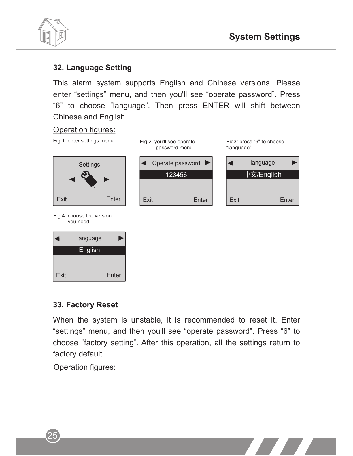
Operation figures:
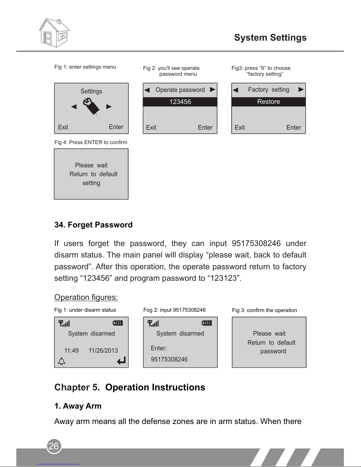
33. Factory Reset
When the system is unstable, it is recommended to reset it. Enter
“settings” menu, and then you'll see “operate password”. Press “6” to
choose “factory setting”. After this operation, all the settings return to
factory default.
Settings
Exit
Fig 1: enter settings menu
Operation figures:
32. Language Setting
This alarm system supports English and Chinese versions. Please
enter “settings” menu, and then you'll see “operate password”. Press
“6” to choose “language”. Then press ENTER will shift between
Chinese and English.
Enter
Exit
Enter
language
中文/English
Exit
Enter
123456
Operate password
Fig 2: you'll see operate
password menu
Fig3: press “6” to choose
“language”
Fig 4:
you need
choose the version
Exit
Enter
language
English
Page 29
System Settings
26
1. Away Arm
Away arm means all the defense zones are in arm status. When there
System disarmed
95175308246
Enter:
System disarmed
Please wait
password
Return to default
Fig 1: under disarm status Fog 2: input 95175308246
Fig 3: confirm the operation
Chapter 5. Operation Instructions
Operation figures:
34. Forget Password
Settings
Exit
Enter
Exit
Enter
Factory setting
Restore
Exit
Enter
123456
Operate password
Fig 1: enter settings menu
Fig 2: you'll see operate
password menu
Fig3: press “6” to choose
“factory setting”
Fig 4: Press ENTER to confirm
Please wait
setting
Return to default
If users forget the password, they can input 95175308246 under
disarm status. The main panel will display “please wait, back to default
password”. After this operation, the operate password return to factory
setting “123456” and program password to “123123”.
11:49 11/26/2013
Page 30
Remote control operation: press arm button [ ] on the remote
control.
Main panel operation: press [ARM]. The system will enter arm status
after the delay time (default: 60seconds)
Main panel operation: press [STAY].
Use main panel keypad to press [STAY]. The screen will display
“system armed”.
Remote control operation: press home arm button [ ] on the remote
control.
Home arm means part of the defense zones are in arm status. When
there's someone at home, it is recommended, for safety purpose, to
enable some of the detectors (such as sensors for door, window,
balcony, etc), and disable the others (such as sensors for the hall or
some places easy to be triggered by person at home).
2. Home Arm
SMS operation: send “operate password#1#” (default operate
password: 123456)
nobody at home, it is required to set all the detectors working. Any
detection source (such as thief, fire, or gas leakage) trigger the
detector, the alarm system will make alarm.
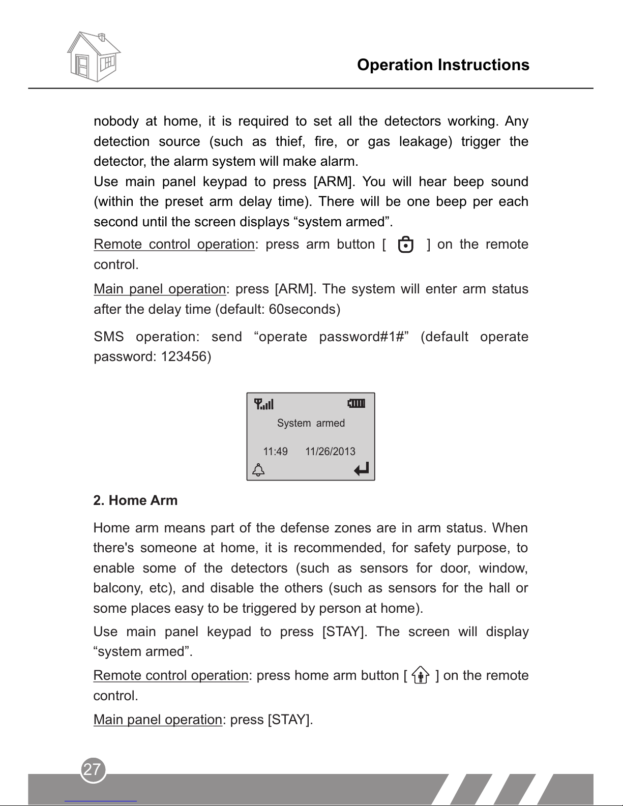
Use main panel keypad to press [ARM]. You will hear beep sound
(within the preset arm delay time). There will be one beep per each
second until the screen displays “system armed”.
Operation Instructions
27
System armed
11:49 11/26/2013
Page 31
Operation Instructions
28
3. Disarm
The purpose of disarming the system is to let it not in alert status. One
way is normal disarming after operation of arming, and the other is to
stop the main unit alarming. After the operation of disarm, all the
defense zones except 24-hour zone shall not work.
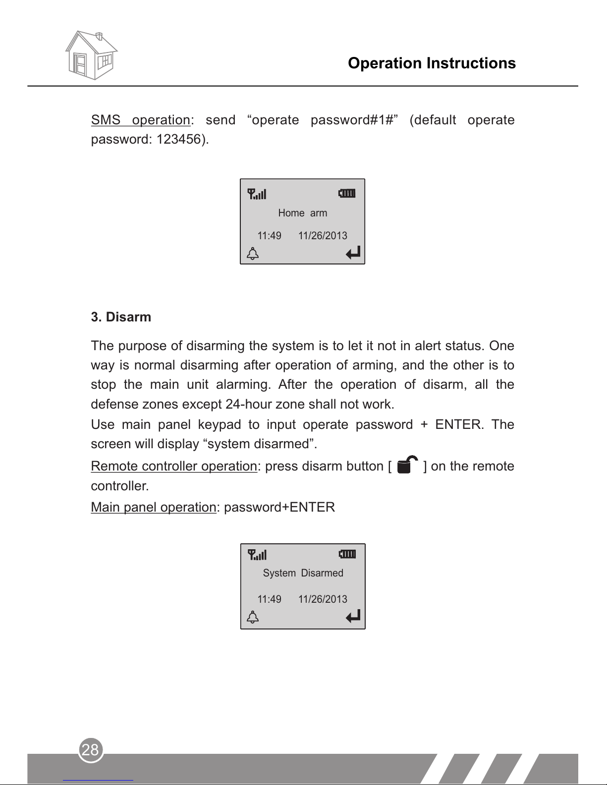
Use main panel keypad to input operate password + ENTER. The
screen will display “system disarmed”.
Remote controller operation: press disarm button [ ] on the remote
controller.
Main panel operation: password+ENTER
SMS operation: send “operate password#1#” (default operate
password: 123456).
Home arm
11:49 11/26/2013
System Disarmed
11:49 11/26/2013
Page 32
Operation Instructions
29
Press [3]: monitoring for 30 seconds, to continue monitoring, press [3]
again to monitor for another 30 seconds.
Press [1]: arm, if finished successfully, you will hear a voice prompt
“System armed”.
Press [2]: disarm, if finished successfully, you will hear a voice prompt
“System disarmed”.
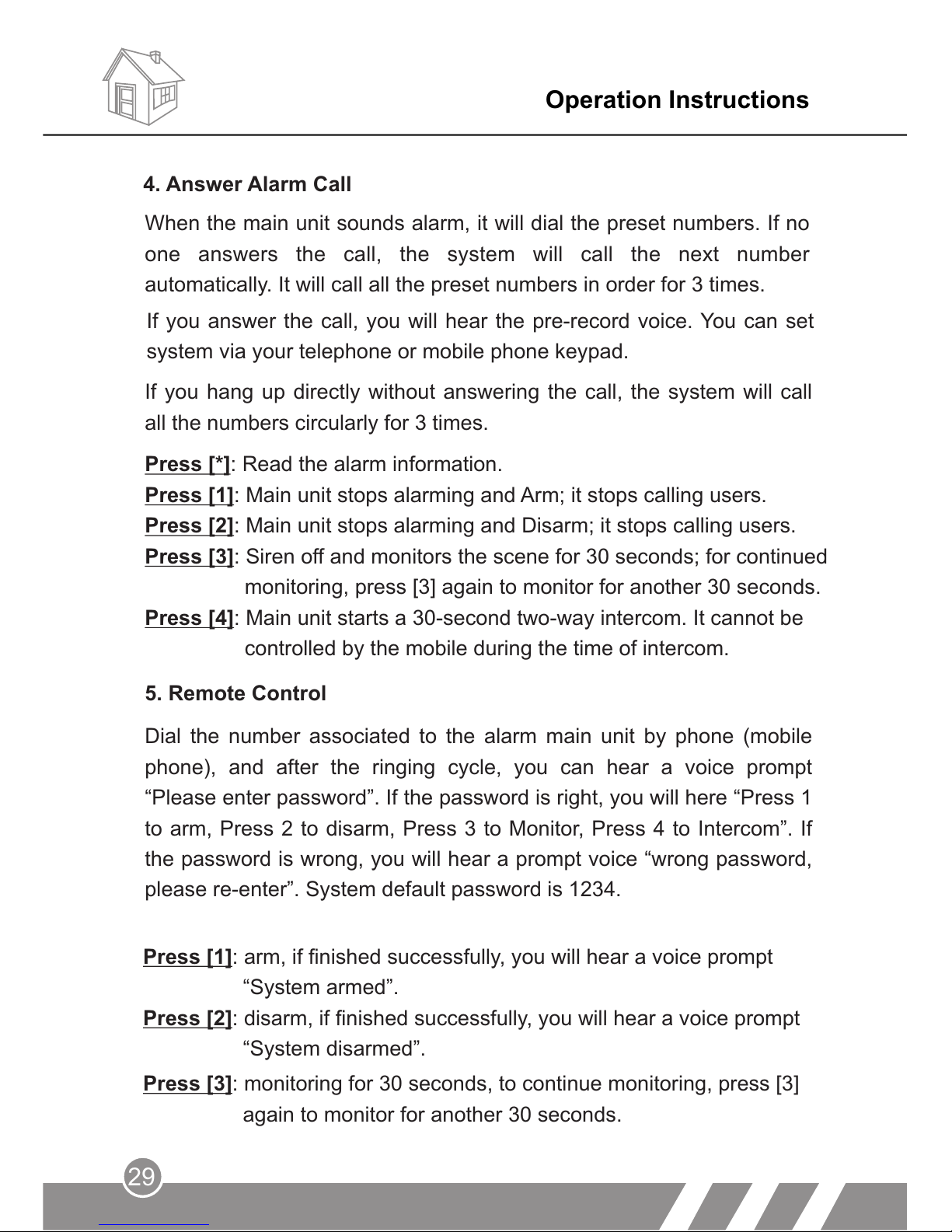
When the main unit sounds alarm, it will dial the preset numbers. If no
one answers the call, the system will call the next number
automatically. It will call all the preset numbers in order for 3 times.
5. Remote Control
Press [*]: Read the alarm information.
Press [1]: Main unit stops alarming and Arm; it stops calling users.
Press [2]: Main unit stops alarming and Disarm; it stops calling users.
Press [3]: Siren off and monitors the scene for 30 seconds; for continued
monitoring, press [3] again to monitor for another 30 seconds.
Press [4]: Main unit starts a 30-second two-way intercom. It cannot be
controlled by the mobile during the time of intercom.
If you answer the call, you will hear the pre-record voice. You can set
system via your telephone or mobile phone keypad.
If you hang up directly without answering the call, the system will call
all the numbers circularly for 3 times.
4. Answer Alarm Call
Dial the number associated to the alarm main unit by phone (mobile
phone), and after the ringing cycle, you can hear a voice prompt
“Please enter password”. If the password is right, you will here “Press 1
to arm, Press 2 to disarm, Press 3 to Monitor, Press 4 to Intercom”. If
the password is wrong, you will hear a prompt voice “wrong password,
please re-enter”. System default password is 1234.
Page 33
Operation Instructions
30
8. Alarming Record Checking
This alarm system can store 30 alarm records. When the record
number exceeds 30, the most previous record will be deleted
automatically.
The icon [ ] will keep flashing if there's alarm record not been
checked.
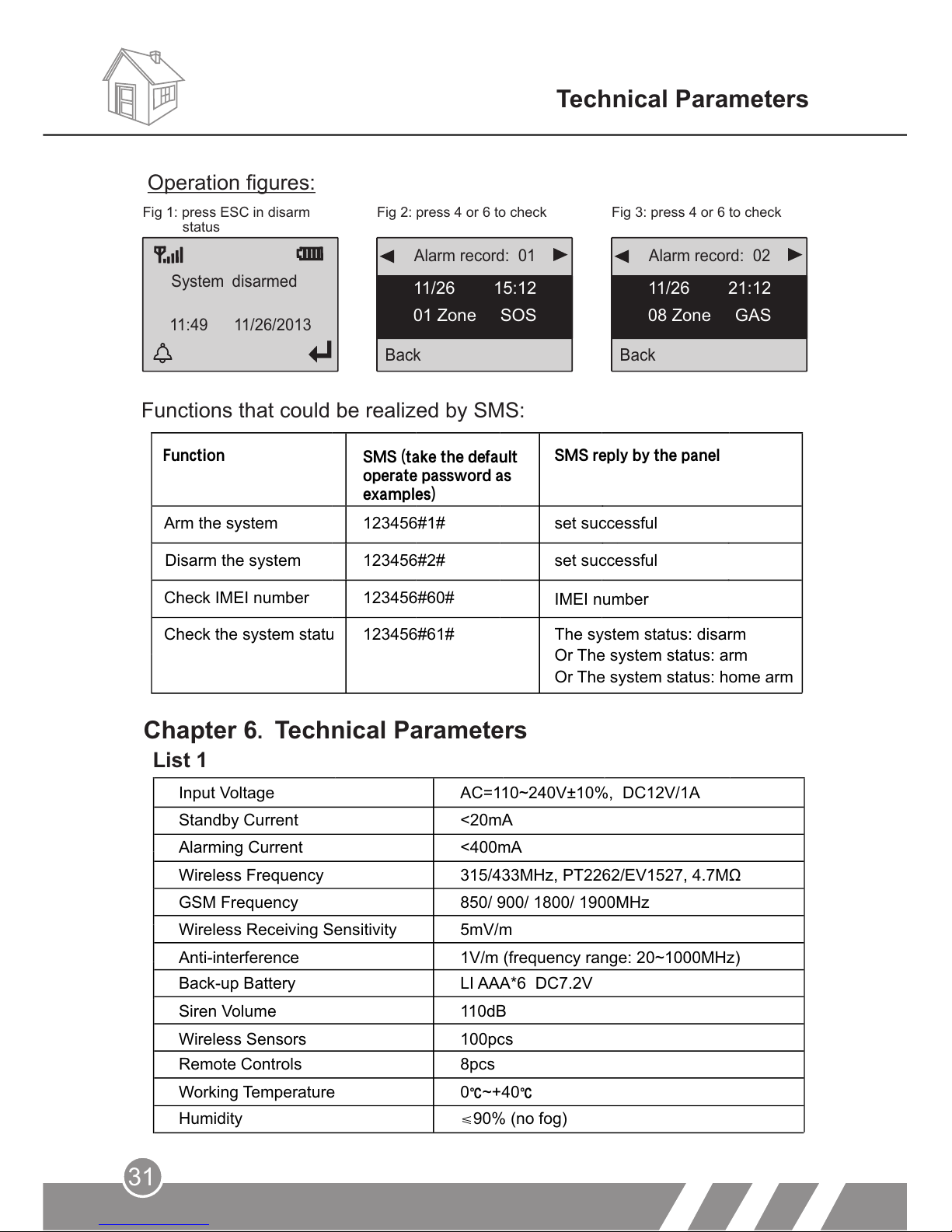
Checking method: In disarm state, input [ESC] button on the panel,
you can check the alarm record. Press “4” or “6” to upturn or downturn,
and press “ESC” to exit checking. If there's not alarm record, it will
display “No alarm record”.
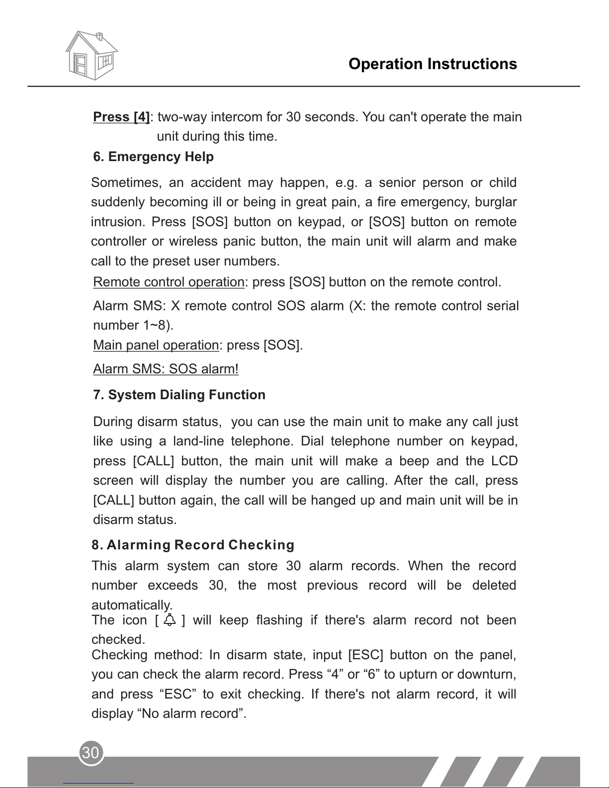
6. Emergency Help
Alarm SMS: SOS alarm!
Main panel operation: press [SOS].
7. System Dialing Function
During disarm status, you can use the main unit to make any call just
like using a land-line telephone. Dial telephone number on keypad,
press [CALL] button, the main unit will make a beep and the LCD
screen will display the number you are calling. After the call, press
[CALL] button again, the call will be hanged up and main unit will be in
disarm status.
Sometimes, an accident may happen, e.g. a senior person or child
suddenly becoming ill or being in great pain, a fire emergency, burglar
intrusion. Press [SOS] button on keypad, or [SOS] button on remote
controller or wireless panic button, the main unit will alarm and make
call to the preset user numbers.
Remote control operation: press button on the remote control. [SOS]
Press [4]: two-way intercom for 30 seconds. You can't operate the main
unit during this time.
Alarm SMS: X remote control SOS alarm (X: the remote control serial
number 1~8).
Page 34
31
Technical Parameters
Back
Alarm record: 02
08 Zone GAS
Back
11/26 15:12
01 Zone SOS
System disarmed
Fig 1: press ESC in disarm Fig 2: press 4 or 6 to check Fig 3: press 4 or 6 to check
Chapter 6. Technical Parameters
List 1
Functions that could be realized by SMS:
Alarm record: 01
Operation figures:
11:49 11/26/2013
11/26 21:12
status
Function
SMS reply by the panel
Arm the system
123456#1#
Disarm the system
123456#2#
Check IMEI number
123456#60#
IMEI number
Check the system status 123456#61#
SMS (take the default
operate password as
examples)
The system status: disarm
Or The system status: arm
Or The system status: home arm
IMEI number
set successful
set successful
Input Voltage
Standby Current
Alarming Current
Wireless Frequency
GSM Frequency
Wireless Receiving Sensitivity
Anti-interference
Back-up Battery
Siren Volume
Wireless Sensors
Remote Controls
Working Temperature
Humidity
AC=110~240V±10%, DC12V/1A
<20mA
<400mA
315/433MHz, PT2262/EV1527, 4.7MΩ
850/ 900/ 1800/ 1900MHz
5mV/m
1V/m (frequency range: 20~1000MHz)
LI AAA*6 DC7.2V
110dB
100pcs
8pcs
0℃~+40℃
≤90% (no fog)
Page 35
32
Chapter 7. Components List
Main panel
Remote controls
Mini wired siren
PIR sensor
Door contact
Power adapter
User manual
1 pc,
1 pc,
1 pc,
1 pc,
1 pc,
1 pc.
2 pcs,
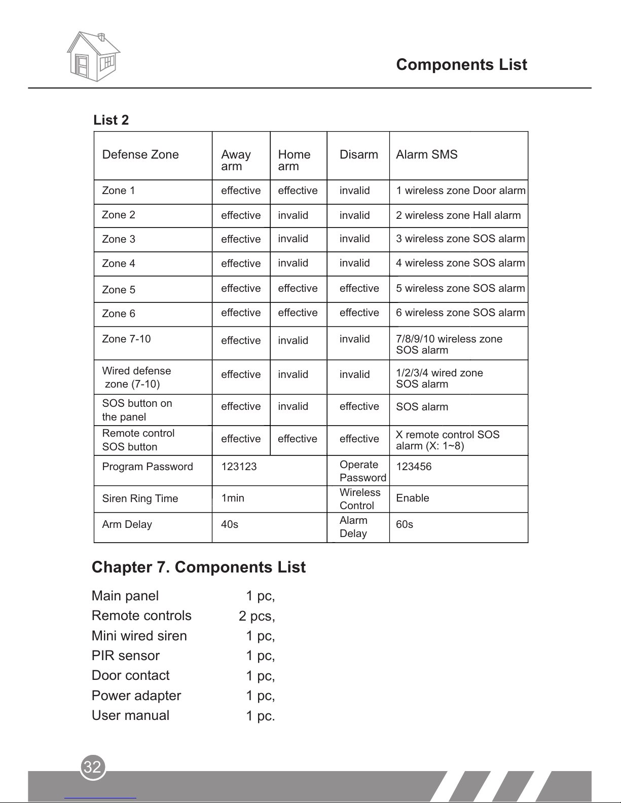
List 2
Components List
Emergency button
Defense Zone
Zone 1
Zone 2
Zone 3
Zone 4
Zone 5
Zone 6
Zone 7-10
Wired defense
zone (7-10)
SOS button on
the panel
Remote control
SOS button
Program Password
Siren Ring Time
effective
effective
effective
effective
effective
effective
effective
effective
effective
effective
invalid
invalid
effective
invalid
effective
invalid
invalid
invalid
invalid
invalid
invalid
invalid
effective
effective
invalid
invalid
effective
1 wireless zone Door alarm
2 wireless zone Hall alarm
3 wireless zone SOS alarm
4 wireless zone SOS alarm
5 wireless zone SOS alarm
6 wireless zone SOS alarm
7/8/9/10 wireless zone
SOS alarm
1/2/3/4 wired zone
SOS alarm
SOS alarm
X remote control SOS
alarm (X: 1~8)
effective effective effective
123123
1min
Arm Delay
40s
Operate
Password
Wireless
Control
Alarm
Delay
123456
Enable
60s
Away
arm
Home
arm
Disarm
Alarm SMS
Page 36
33
Care and Maintenance
Place the control panel and all parts and accessories out of
children's reach.
Keep the alarm system dry. Rain, humidity and various fluids or
moisture all will corrupt the electronic circuit.
Do not use or place the alarm system in dirty locations, otherwise
the electronic elements will be damaged.
Do no place the system in excessively hot locations. High
temperature will shorten the service life of electronic equipment,
damage batteries, deform or even melt some plastic parts.
Do not place the system in excessively cold locations. Otherwise
condensation many occur and damage the circuit board of the
alarm system.
It is recommended that you check and test the alarm system
periodically:
Check the main unit every three months:
Whether it can arm/disarm normally;
Whether it can dial the number for alarm normally;
Whether it can receive wireless detectors' signal normally;
Whether the back-up battery can work normally.
Check the wireless detectors once a month:
Trigger wireless detectors to see if system can alarm normally;
Check all detectors' batteries to see if it's in low voltage;
Check whether wireless detectors can send signal to the main unit
normally.
1.
2.
3.
4.
1.
2.
3.
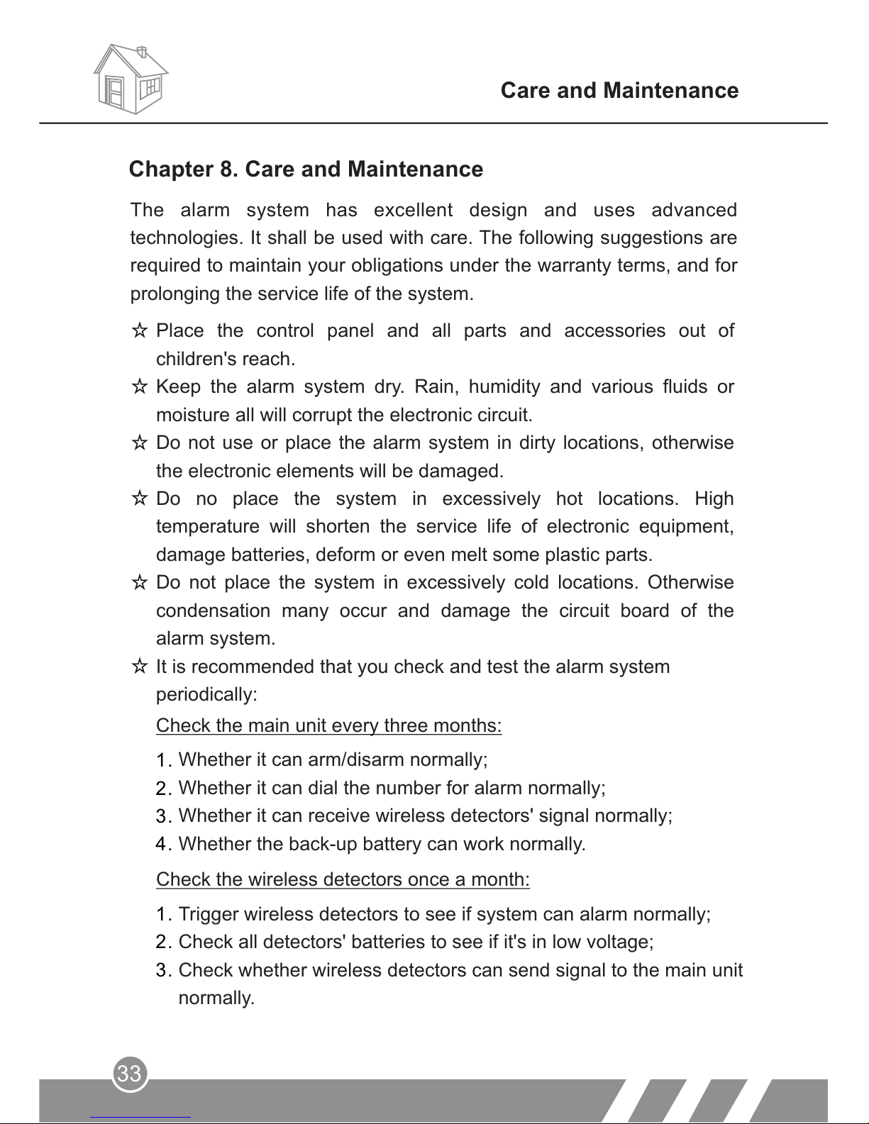
Chapter 8. Care and Maintenance
The alarm system has excellent design and uses advanced
technologies. It shall be used with care. The following suggestions are
required to maintain your obligations under the warranty terms, and for
prolonging the service life of the system.
Page 37
Care and Maintenance
Check the SIM card:
Check the use of SIM card, such as network signal, balance, etc.
Make sure the PIN code verification of the SIM card is closed.
Please keep the password and SIM card number safe, in case that
other people remote control the system illegally.
Since the alarm system is continuously in operation or standby
mode, the supply adaptor of the control panel shall be connected to
a safe and reliable socket.
Do not place the system near your bedroom or office table, because
the siren will make high-loudness sound in the case of alarm, which
may adversely affect your rest or work.
If the alarm system will not be used for a long time, please
disconnect the system from the power supply.
Please do not disassemble, repair or alter the products without
permission, or it may cause accidents and faults.
Do not drop this product on the ground or on hard objects, as it may
lead to massive impact to cause faults and damages.
Without approval and consent of relevant authorities, please do not
set “112”, “911” or the alarm phone number of police station for this
main unit.
1.
2.
3.
Please read the suggestions above carefully and follow the instructions
herein. If any of the equipment does not work properly, please send it
to the dealer or authorized service point for repair. We will try our best
to solve the problem for you as soon as possible.
34
Page 38
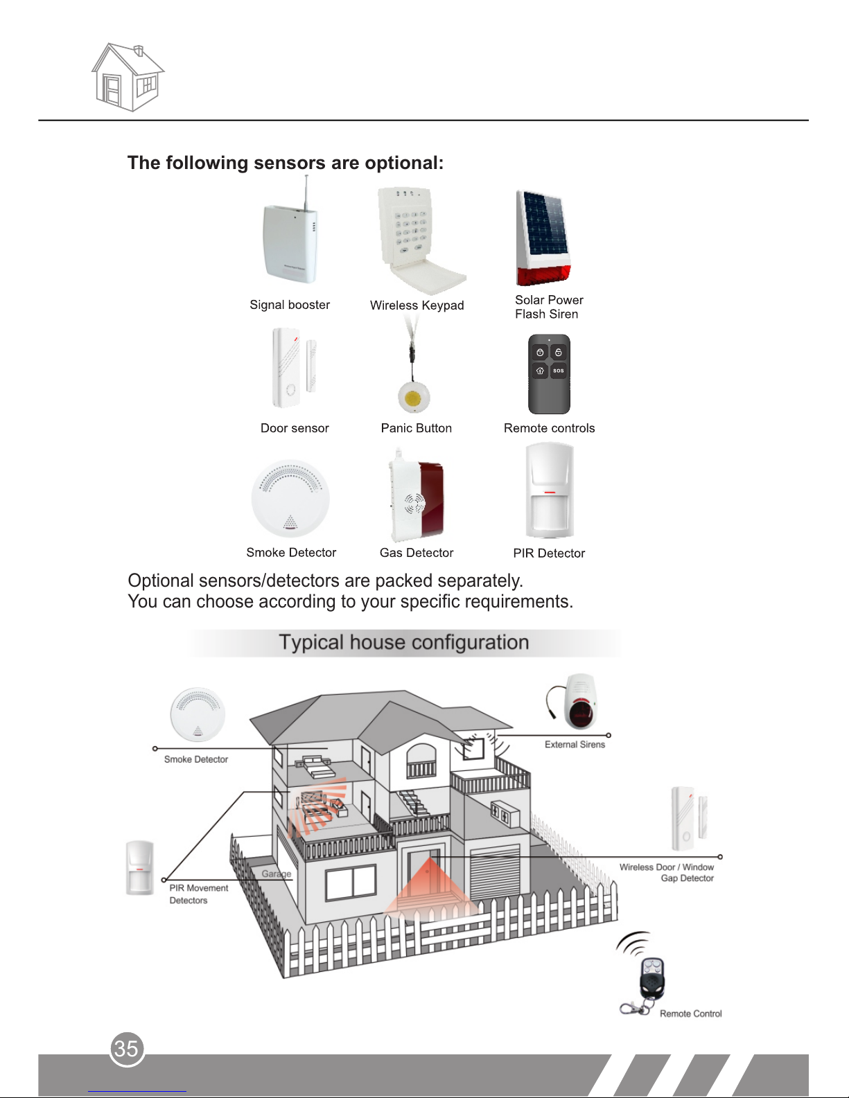
The following sensors are optional:
Optional sensors/detectors are packed separately.
You can choose according to your specific requirements.
35
Page 39
MOBILE CALL
GSM Alarm System
3 12 1
-EN
 Loading...