

GSM GSM-888 Instruction Manual
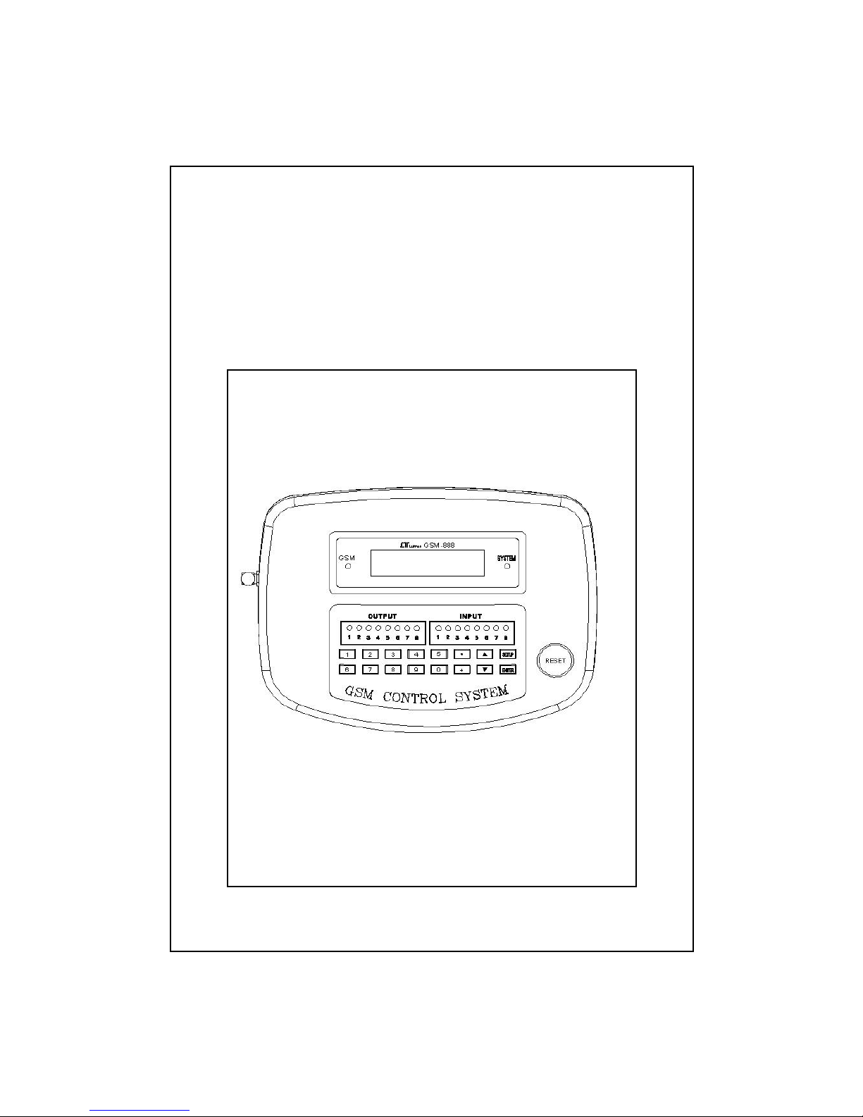
GSM
CONTROL SYSTEM
Model : GSM-888

TABLE OF CONTENTS
1. FEATURES................................................................1
2. APPLICATION........................................................... 2
3. SPECIFICATIONS......................................................3
4. FRONT PANEL & LAYOUT DESCRIPTION....................
.
5
5. SIM CARD ACQUISITION and INSTALL...................... 8
6. OPERATION PREPARING...........................................
.
9
7. FUNCTION SETUP.....................................................10
7-1 AD ( Analog input, 4-20 mA )...............................10
7-2 IO ( Switch input, Relay output )..........................15
7-3 TEL ( Telephone )................................................17
7-4 RP ( Ring period )................................................ 19
7-5 IM ( Switch input management )..........................
.
20
7-6 SAVE..................................................................
.
21
8. SMS COMMAND from MOBILE
CONFIRM SMS from SYSTEM
ERROR SMS COMMAND
ALARM SMS from SYSTEM.........................................22
9. IMPORTANT OPERATION PROCEDURES and
CONSIDERATION..................................................... 31
10. TROUBLE SHOOTING..............................................36
11. UNIT LIST of ANALOG INPUT..................................
.
38
12. FULL LINE TRANSMITTERS, optional........................40

1. FEATURES
*Control/Monitor/Alarm via GSM mobile phone, no
distance limitation. User can control/monitor/alarm their
device from over the world.
*8 channels Analog input ( 4 -20 mA ), can cooperate full
line industrial 4-20 mA transmitters.
*8 Relay outputs.
*8 Switch inputs, normal open, close alarm.
*8 Analog inputs : system can preset 4 mA and 20 mA
input value according the real measuring value and setting
display unit. It can read actual measuring data via the
SMS ( Short Message ) requesting, such as CH1= 28.0 C.
CH2=53.7 %RH, CH3=7.01 pH........CH8= 230.5 ACV.
*Setting Analog input alarm ( High alarm, Low alarm ) to
enable or disable via SMS.
*Setting Input switch alarm ( close alarm ) to enable or
disable via SMS.
*Relay output On/Off setting via SMS.
*Dot matrix LCD display, show Analog input value, Switch
input and Relay output status.
*All setting value will be saved into EPROM IC, no loss.
*Mobile telephone can call all channel measuring value,
status of Switch input and Relay output at any time.
*Can default two telephone no., alarm SMS can be
send to two users.
*Build GSM mobile modem ( dual band ).
*After the SMS command send by mobile phone,
the confirm message will be send back to the
mobile, safety and no loss.
1

*Intelligent application , innovation, wide range, no
limitation.
*Full line industrial 4-20 mA transmitters are available
from LUTRON : ACV, ACA, DCV, DCA, Hz, WATT, VAR,
Power Factor, Humidity, Temperature ( type K, Pt 100
ohm ), Pressure, Vibration, Sound Level, RPM, pH,
Conductivity, Dissolved, TDS, ORP, RPM, Air velocity,
Light, Clamp current, Load Cell, Potential, Angle, EMF, IR,
UV light, Moist
ure…, detail please refer the
LUTRON
Transmitter catalog ( www.lutron.com.tw ).
2. APPLICATION
*Industrial remote monitor/controller/alarm system.
*Industrial security system.
*Home security system.
*Building supervision.
*Industrial systems.
*Pumping stations.
*Power station.
*Agriculture usage.
*Animal husbandry.
*Water supply systems.
*Traffic systems.
*Railway systems/Vehicles.
*Energy systems.
*Water clarification.
*Heating power plants.
2
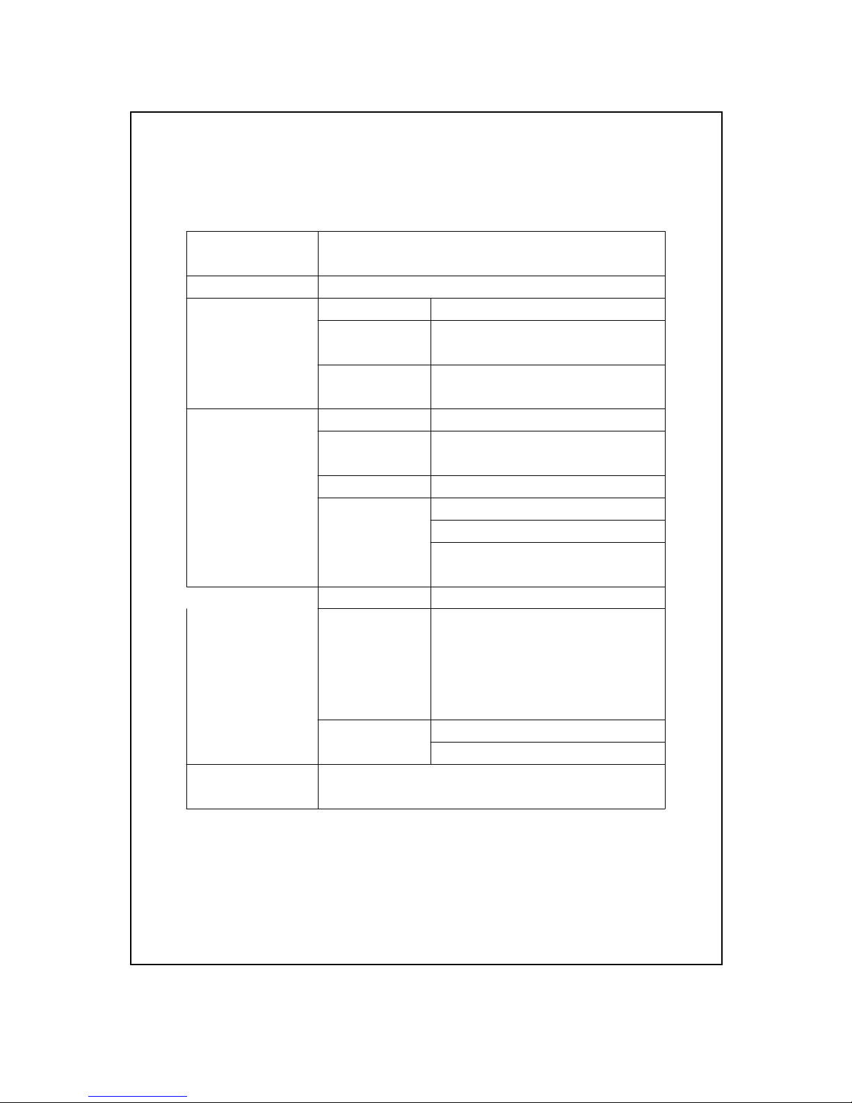
3. SPECIFICATIONS
DISPLAY Dot-matrix LCD with back light
16 characters x 2 line.
GSM Modem 900/1800 MHz, dual band.
Switch inputs Number 8 inputs
Reaction 200 mS, min.
time
Status Default open,
Close will alarm
Analog input Number 8 channels
4 to 20 mA Input 125 ohm
impedance
Resolution 12 bits A/D converter
Setting 4 mA. 20 mA setting
by front Unit setting
buttons High/Low alarm value
setting
Relay outputs Number 8 relays
Function Relay 1 to Relay 7 can
control by mobile via SMS
Relay 8 is the alarm relay
used to connect to field
alarm system
Max load 1 ACA/250 ACV
1 DCA/24 DCV
Standard CE conformity
3
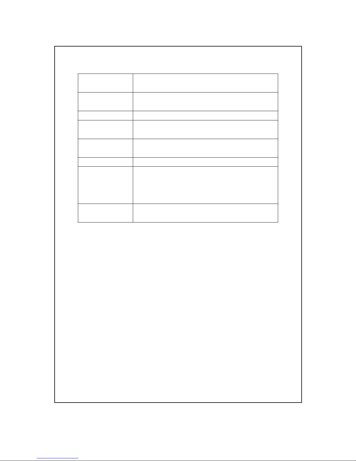
Operating 0 to 50 ( 32 to 122 )℃℉
Temperature
Operating Less than 80% RH.
Humidity
Power supply DC 9V.
Power Less than 400 mA DC.
consumption
Size 193 x 149 x 46 cm
( 7.6 x 4.9 x 1.8 inch ).
Weight 592 g ( 1.3 LB ).
Accessories Operation manual....................... 1 PC
includes AC ( 100 -240 V )/DC ( 9V, 1 Amp )
power adapter............................ 1 PC
A
ntenna .................................... 1 PC
Accessories Full line 4 to 20 mA industrial
optional transmitters, refer page 40
4
3. FRONT PANEL & LAYOUT
DESCRIPTION
Fig. 1
Fig. 2
5
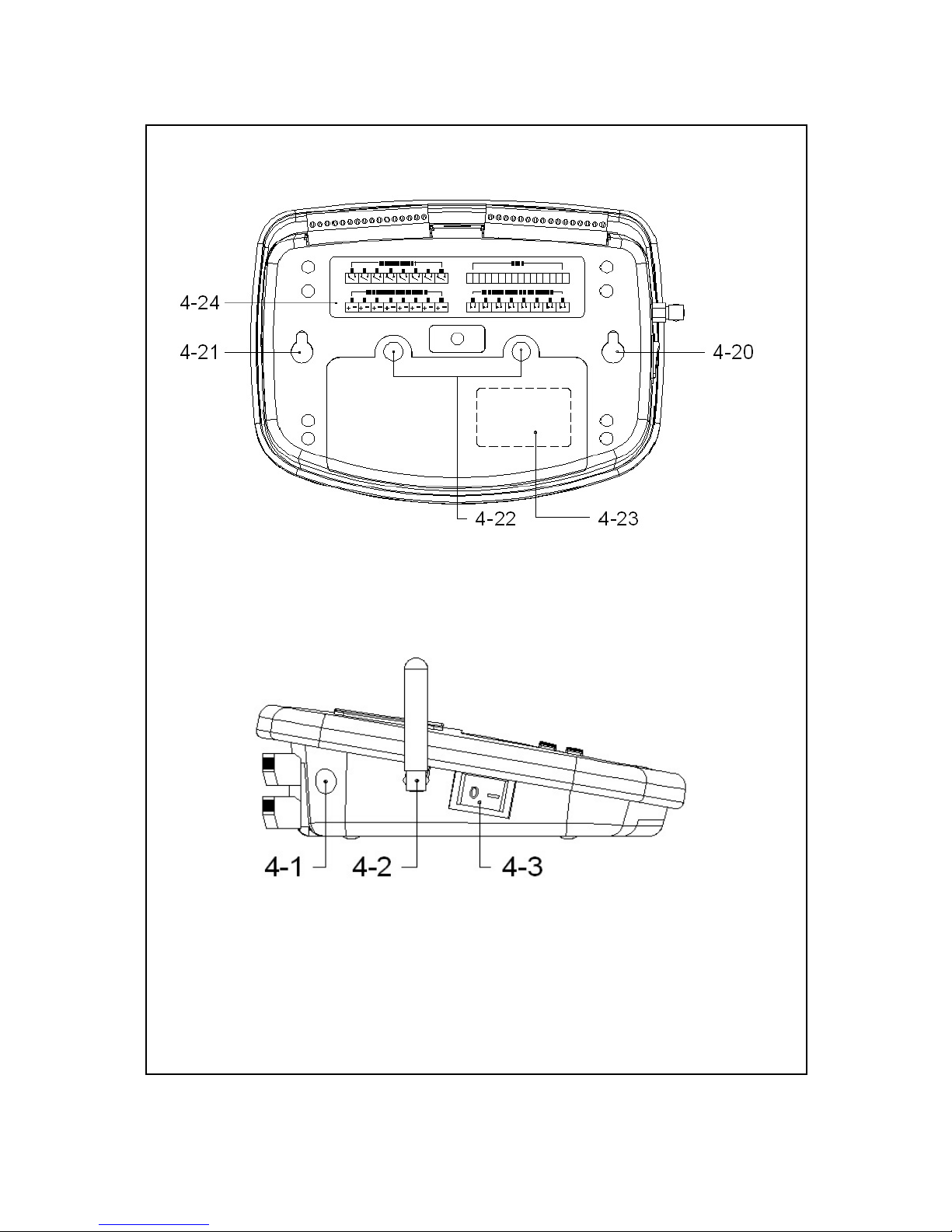
Fig. 3
Fig. 4
6

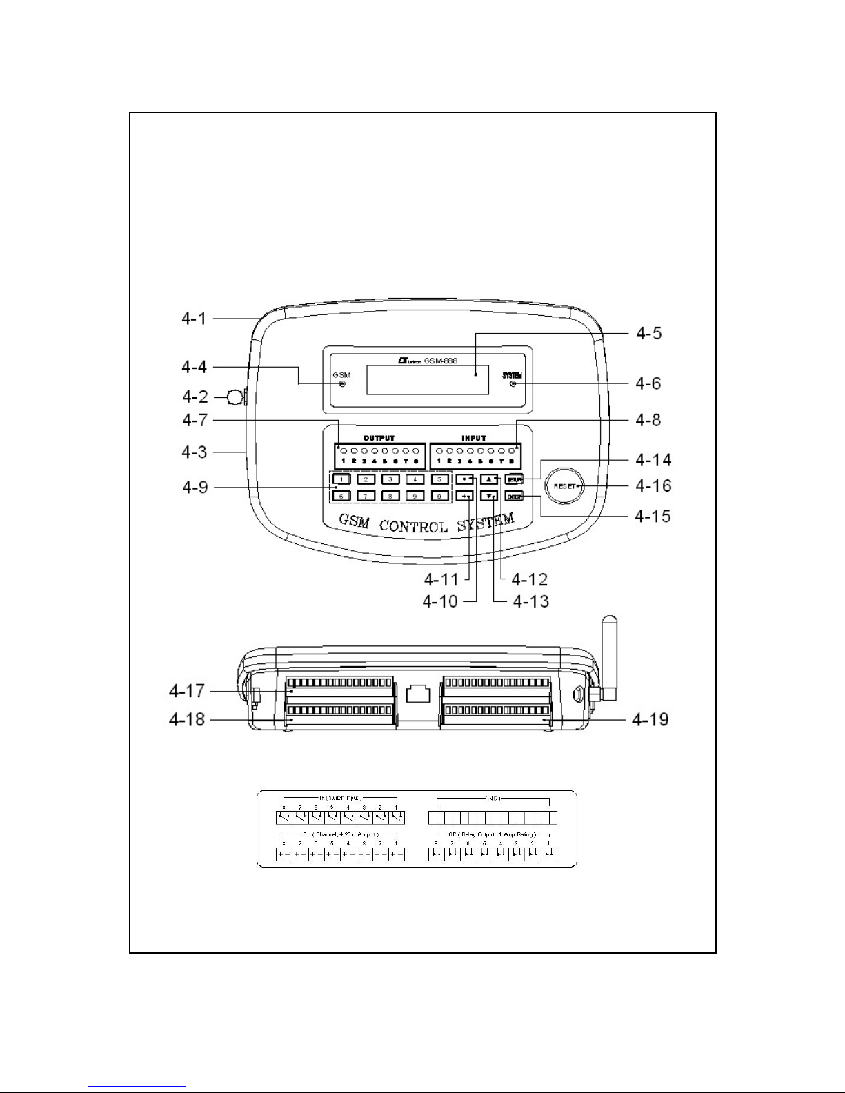
4-1 DC 9V power adapter socket
4-2 Antenna and Antenna socket
4-3 Power On/Off switch
4-4 GSM indicator
4-5 LCD display
4-6 System indicator
4-7 Relay output indicator
4-8 Switch input indicator
4-9 Numerical buttons
4-10 Decimal button
4-11 + - button
4-12 button▲
4-13 button▼
4-14 SETUP button
4-15 ENTER button
4-16 RESET button
4-17 IP ( Switch input ) terminals
4-18 CH ( Analog input, 4-20 mA input ) terminals
4-19 OP ( Relay output ) terminals
4-20 Fix hole for wall installation
4-21 Fix hole for wall installation
4-22 Screws for the SIM card cover
4-23 SIM card holder
4-24 Terminal instruction label
7

5. SIM CARD ACQUISITION
and INSTALL
1)Obtain your personal SIM card from the mobile
telephone company of your choice.
You will receive a telephone number and a PIN code
with your SIM card.
2)Cancel the SIM card's PIN code.
( No PIN code when use the SIM card )
The procedures to cancel the PIN code,
please use your own mobile to proceed as
the instruction manual.
Note :
To cancel the PIN code is the necessary
procedures, otherwise your GSM system will
be not working properly.
3)To guarantee flawless operation of your GSM
Control System, ensure that adequate signal
strength is permanently to and from your
mobile telephone network. Check this with
your mobile before installation.
4)Open the SIM card cover by loosing the " Screws for
the SIM card cover " ( 4-22, Fig. 3 ). Install the SIM
card properly into the " SIM card holder " ( 4-23, Fig. 3 ).
8
6. PREPARING OF OPERATION
1)Install the SIM card, refer above chapter 5, page 8.
2)Install the antenna to the Antenna socket " ( 4-2,
Fig. 1 ) properly.
3)Connect the plug of the Power Adapter into
" DC 9V power adapter socket " ( 4-1, Fig. 1, Fig. 4 )
4)Power on the unit by engage the " Power On/Off
switch " ( 4-3, Fig. 1, Fig 4 ) to the ON position.
5)LCD display, System indicator and Output indicator :
* The LCD will lit and count down from
90 seconds back to 0 second then present the
SETUP SCREEN ( refer page 10 ).
* The " Output indicator " ( 4-7, Fig. 1 ) will show
the default Relay On/Off status, if the Relay On
the " Output indicator " will lit.
* The " System indicator " ( 4-6, Fig. 1 ) will flash
( per 1 second On, 1 second Off ) if the CPU Circuit
working properly.
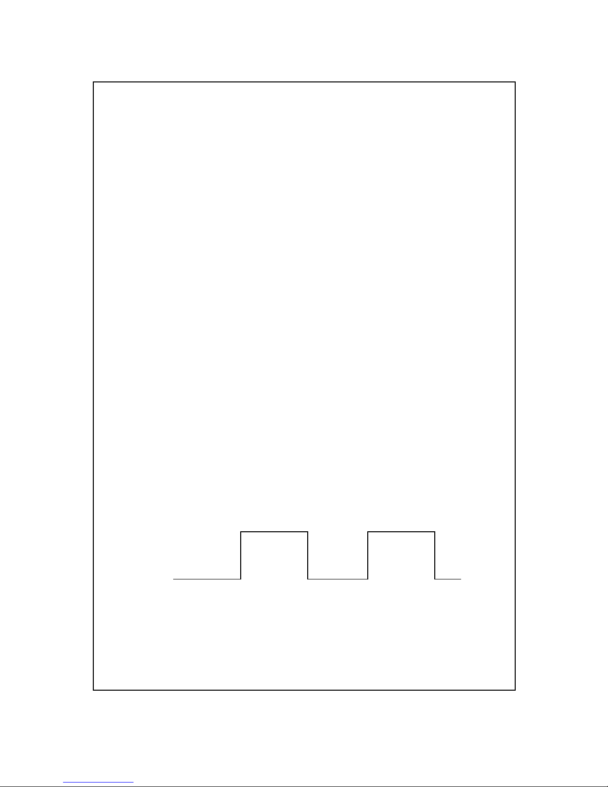
6)GSM indicator ( 4-4, Fig. 1 )
a.If the GSM modem is not connecting the mobile
network, the " GSM indicator " will flash per
0.6 second On and 0.6 second Off.
0.6 second On
0.6 second Off
9
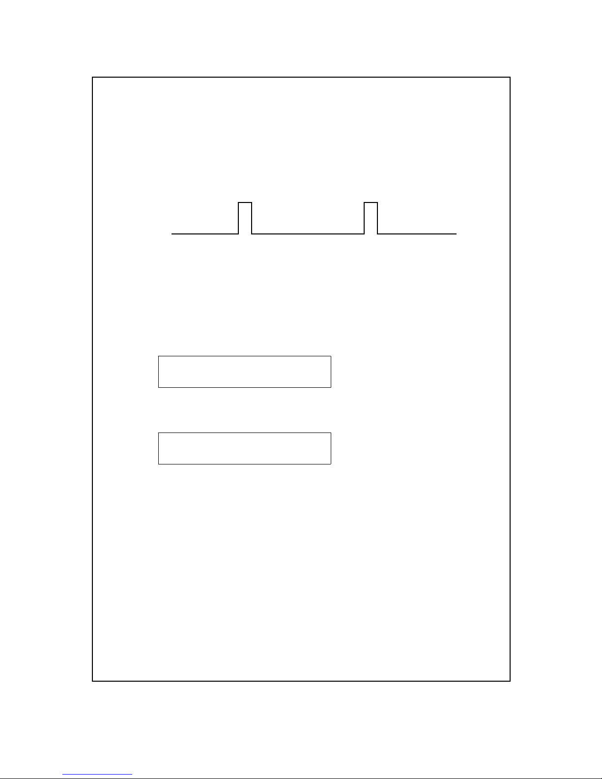
a.If the GSM modem connect to the mobile
network properly, the " GSM indicator " will flash per
0.075 second On and 3 second Off.
0.075 second On
3 seconds Off
7. FUNCTION SETUP
7-1 AD ( 4-20 mA Analog input )
1)Push the " SETUP Button ", the LCD will show
1:AD 2:IO 3: TEL SETUP SCREEN
4:RP 5:IM 6:SAVE
* key in " 1 ", LCD will show
CH1 4 mA Value CH1 4 mA setting SCREEN
xxxx :
* Use the following buttons
Numerical buttons ( 4-9, Fig. 1 )
Decimal button ( 4-10, Fig. 1 )
+ - button ( 4-11, Fig. 1 )
@ + - button is used to key in " minus " value
to key in the desired channel 1 4 mA value ( 4 mA
= real display value ). For example 4 mA = 0
* After finish to key in the desired value, should press
the " ENTER " key.
10
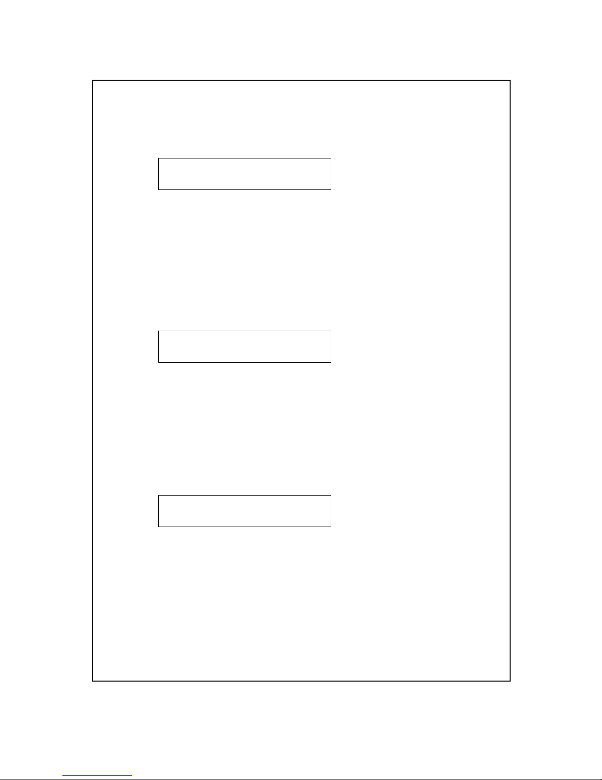
* Press " button " ( 4-12, Fig. 1 ) once, LCD will show▲
CH1 20mA Value CH1 20 mA setting SCREEN
xxxx :
* Press the buttons ( 4-9, 4-10 , Fig. 1 ) to key in
the desired channel 1 20 mA value ( 20 mA = real
display value ). For example 20 mA = 100.0
* After finish to key in the desired value, should press
the " ENTER " key.
* Press " button " once again, LCD will show▲
CH1 High Limit CH1 High Limit setting SCREEN
xxxx :
* Use the buttons ( 4-9, 4-10, Fig. 1 ) to key in
the desired channel 1 High Limit value.
For example High Limit Value = 80.0
* After finish to key in the desired value, should press
the " ENTER " key.
* Press " button " once again, LCD will show▲
CH1 Low Limit CH1 Low Limit setting SCREEN
xxxx :
* Use the buttons ( 4-9, 4-10, 4-11, Fig. 1 ) to key in
the desired channel 1 Low Limit value.
For example Low Limit Value = -20.0
* After finish to key in the desired value, should press
the " ENTER " key.
11
 Loading...