

GSL SWB1000-12, SWB1800-12, SWB1000-24, SWB1800-24, SWB2500-12 Operating Instructions Manual
...
Page 1 of 4
Unit 2, 110 Station Rd, Seven Hills ,NSW, 2147, Australia
Traveller Series
240VAC Sine Wave Power Inverter
Operating Instructions
Please read these instructions before use
Features include:
• Microprocessor-based design with accurate and stable frequency • Capable of driving inductive loads, i.e. electric
tools and appliances • Low Battery Shut Down • Input voltage (12V Models 10-15VDC) (24V Models 21-30VDC) •
Output voltage 235-245VAC, Pure Sine Wave @ 50Hz
• Low harmonic distortion (3%≤) • Compact, rugged and designed with (82-85%≥) efcient • Aluminium chassis for
harsh environments and easily mounted
Safety Instructions:
WARNING! - Professional electrical / renewable energy installer should perform the installation, as dangerous
voltages can be present. Before installing and using your inverter, read the Installation Instructions!
Explosive Gas Precautions:
This equipment contains components that can produce arcs or sparks. To prevent re or explosion do not install in
compartments containing batteries or ammable materials, or in locations that require ignition-protected equipment.
This includes any space containing petrol-powered machinery, fuel tanks, joints or other connections between
components of the fuel system.
Precautions When Working With Batteries:
• If battery acid contacts skin or clothing, wash immediately with soap and water. If acid gets into eyes, immediately
ood eyes with running cold water for at least 20 minutes and get medical attention immediately. NEVER smoke,
allow a spark or ame in the vicinity of batteries or engine. Do not drop a metal tool on the battery as the resulting
spark or short-circuit of the battery may cause an explosion.
• Remove personal metal items such as rings, bracelets, necklaces, and watches when working with a lead-acid
battery. A lead-acid battery produces a short-circuit current, high enough to weld a ring or similar metal, causing a
severe burn.
WARNING! - Shock Hazard! Before proceeding further, ensure that the Inverter is NOT connected to any
Batteries, and that all wiring is disconnected from any electrical Sources. Do not connect the 0utput Terminals of
the Inverter to an incoming AC sources.
WARNING! - Reverse polarity connection will blow the internal fuse and may damage the inverter permanently.
Before installing your inverter, please make sure that you have appropriately sized batteries. A battery that is too
small in capacity will not allow the inverter to perform to its full specication. The DC cabling must be connected to
the correct polarity terminals of the battery bank. (Red = Positive, Black = Negative).
DO NOT extend the DC cable length to the inverter unless you are prepared to increase the diameter of the cable. If
this is necessary consult your supplier or installer for advice.
SWB240R-R2
Model:
SWB1000-12, SWB1000-24
SWB1800-12, SWB1800-24
SWB2500-12, SWB2500-24
Page 2 of 4
Unit 2, 110 Station Rd, Seven Hills ,NSW, 2147, Australia
Traveller Series
240VAC Sine Wave Power Inverter
Operating Instructions
Please read these instructions before use
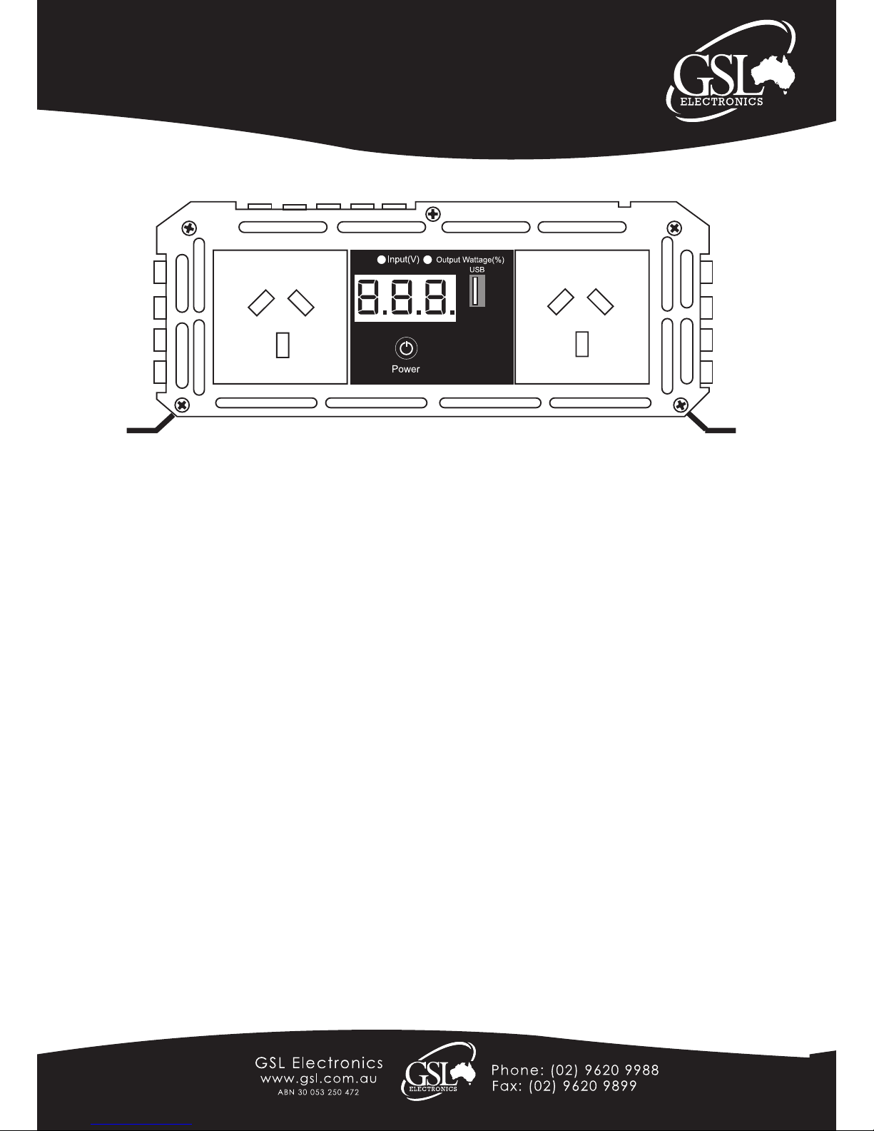
1. Controls and indicators:
The POWER switch turns the control circuit in the power inverter on and off. It does not disconnect power from the power
inverter.
To turn ON: Press the power button 3-5 seconds then the inverter will start.
2. Input Voltage Indication:
By default this enabled and is indicated by the “Input(V)” LED being lit. If the unit is in “Output Wattage(%)” Mode, press
the POWER button once to toggle to Input Voltage.
When in Input Voltage mode it will display on the three digit display a reading of the battery voltage.
3. Output Wattage:
The “Output Wattage(%)” LED indicates that the display now reads the Output Wattage being consumed represented as
a percentage of the maximum opperating wattage.
To toggle the display to this mode, Press the POWER button once quickly.
Installation
1. Where to install - The power inverter should be installed in a location that meets the following requirements:
Dry – Do not allow water to drip or splash on the inverter and in an area free of salt or moisture-laden air.
Temperature – Ambient air temperature should be between 0º and 40º.
Ventilation – Allow at least twenty-ve millimeters / one inch of clearance around the inverter for airow. Ensure the
ventilation openings on the rear and bottom of the unit are not obstructed. The installation site should not be susceptible
to temperatures in excess of 50ºC.
Safety – Do not install in a battery compartment or other areas where ammable fumes may exist, such as fuel storage
or engine compartments.
Dust-free – Do not install the inverter in an environment where there are dust, wood particles, metal lings and
shavings. These can be pulled into the unit blocking the cooling fans.
Close to battery / batteries – Avoid excessive cable lengths (Mount the inverter between one and two metres from
the batteries) but do not install the inverter over or in the same compartment as batteries. Use the recommended wire
lengths and sizes. Do not mount the inverter where it will be exposed to the gases produced by the battery. These gases
are very corrosive and prolonged exposure will damage the inverter.
SWB240R-R2
Model:
SWB1000-12, SWB1000-24
SWB1800-12, SWB1800-24
SWB2500-12, SWB2500-24
Front view, main functions & Operation:

Page 3 of 4
Unit 2, 110 Station Rd, Seven Hills ,NSW, 2147, Australia
Traveller Series
240VAC Sine Wave Power Inverter
Operating Instructions
Please read these instructions before use
SWB240R-R2
Model:
SWB1000-12, SWB1000-24
SWB1800-12, SWB1800-24
SWB2500-12, SWB2500-24
2. Making DC Wiring Connections: Follow this procedure to connect the battery cables to the DC input terminals on the
inverter. Your cables should be as short as possible (ideally, less than 10 feet / 3 metres).
a. Unpack and inspect the power inverter, check to see that the power switch in the OFF position.
b. Connect the DC POSITIVE cable to the Positive (POS+) terminal on the battery.
c. Connect the cable to the Positive terminal on the inverter.
d. Connect the DC NEGATIVE cable to the Negative terminal on the inverter.
e. Connect the cable to the Negative (NEG-) terminal of the battery. This should be the last connection made. A spark
when making this nal connection is normal.
CAUTION! - Reversed polarity connections will blow a fuse in inverter and may permanently damage the inverter.
Damage caused by a reverse polarity connection is not covered by our warranty.
WARNING! - You may observe a spark when you make this connection. Do not make this connection in
the presence of ammable fumes. Explosion or re may result.
WARNING! - Make sure all the DC connections are tight. Loose connections will overheat and could
result in a re hazard.
Maintenance:
Helpful Tip to Conserve Battery Power
Should the inverter not be used over an extended period of time, it is recommended that the battery be disconnected
from the inverter. This will ensure battery will not be drained over the period of non-usage.
Very little maintenance is required to keep your inverter operating properly. You should clean the exterior of the unit
periodically with a damp cloth to prevent accumulation of dust and dirt. At the same time, tighten the screws on the DC
input terminals.
WARNING!
Do not open or disassemble inverter. Attempting to service the unit yourself may result in a risk of electrical shock or re.
Opperation:
1) Press the power button for 3-5 Seconds, Unit will turn ON.
2) If the Left indicator is on then the Display will show the Input Voltage
3) If you desire to see the output power being used as a percentage press the power button with a quick short press
once. Now the Right LED will be lit and the display will show the Output Power Consumpton as a Percentage of the
total watts of the unit.
4) If you wish to return to viewing the Input Voltage press the power button quickly once more.
5) To turn OFF the unit press the power button for 3-5 Seconds.

Page 4 of 4
Unit 2, 110 Station Rd, Seven Hills ,NSW, 2147, Australia
Traveller Series
240VAC Sine Wave Power Inverter
Operating Instructions
Please read these instructions before use
SWB240R-R2
Model:
SWB1000-12, SWB1000-24
SWB1800-12, SWB1800-24
SWB2500-12, SWB2500-24
Continuous Power 900W 1620W 2250W
30Min Max Power 1000W 1800W 2500W
Working Voltage Range
12V = 10.5V±0.3 - 15.5V±0.5
24V = 21V±0.3 - 31V±0.5
Rated Input DC Voltage Range
12V = 12.8V-13.2V
24V = 25.6V - 26.4V
Output Voltage 235-245V
Output Frequency Range 50±0.3Hz
≥85%
≥82%
No Load Power Current (at rated input DC voltage)
12V ≤0.8A
24V ≤0.6A
12V ≤1.2A
24V ≤1.2A
12V ≤1.5A
24V ≤1.2A
Over-Voltage Shut Down (No Load)
12V = 15V - 16.5V
24V = 30V - 33V
Low Voltage Alarm (No Load)
12V = 10.7±0.3V
24V = 21.4±0.6V
Low Voltage Shut Down ( No Load)
12V = 10±0.3V
24V = 20±0.6V
Restart Voltage after Low Voltage condition
12V = 12±0.3V
24V = 24±0.3V
Internal Fuses
12V/(24V)
35A x 4
(20A x4)
30A x 8
(15A x 8)
40A x 8
(20A x 8)
Sine Wave Observation Smooth, No Burr (No Load or Load)
Total Harmonic Distortion ≤3%
Fan Control Thermal and Load Controlled
Over Temperature Cutout 60°C - 70°C
Overload Protection (sustatined 5-30sec) 1230W 2050W 2750W
USB 5V 1A
Working Temerature Range -10°C - 40°C
Warranty Conditions: Our products come with guarantees that cannot be excluded under the Australian Consumer Law.
The customer is entitled to a replacement or refund for a major failure and compensation for any other reasonably foreseeable loss or damage.
The customer is also entitled to have the products repaired or replaced if the products fail to be of acceptable quality and the failure does not
amount to a major failure.
GSL Electronics (GSL) warrants that its products will, under normal use and service, be free of defects in material and workmanship for a period
of two (2) years from the date of the original purchase by the customer as marked on the customer’s original invoice. Please refer to our website
for full warranty and return information.
 Loading...