

Page 4 of 4
Unit 2, 110 Station Road, Seven Hills ,NSW, 2147, Australia
Traveller Series
240VAC Sine Wave Power Inverter
Operating Instructions
Please read these instructions before use
SW240R-R1
Model:
SW150-12, SW650-24
SW350-12, SW1200-24
SW650-12, SW1800-24
SW1200-12, SW3000-24
SW1800-12, SW3000-12
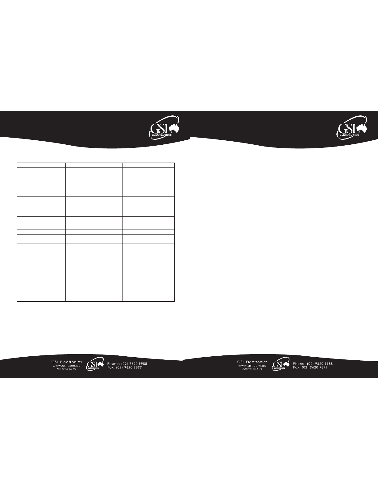
Symptom Possible Cause Solution
AC output will not stay ON Some loads may be to small to hold
inverter ON
Increase size of load
Inverter shuts down due over
temperature
Insufficient ventilation around inverter
Ensure true power rating of appliance
(including power factor) is less than
inverter output rating
Improve ventilation
Check ratings and reduce with different appliance
Inverter shuts down when trying
to start a load
Possible surge from motor starting
causing shut down
Check that battery voltage is within
specification. If voltage drops excessively when starting, batteries
size may have to be increased. Or
load is too large for inverter.
Load LED flashes Overload Reduce load. Remove load.
Under Voltage LED flashes Low input voltage Check battery status. Re-charge
if required.
Over Temp LED flashes Thermal shutdown Improve ventilation.
Over Voltage LED flashes Excessive input voltage Check input voltage. Reduce if too
high.
TV channel interference on
some channels
Connection of chassis ground lug at
rear of inverter needs attention.
High power loads being used during
TV viewing.
Ensure TV antenna providing a good
signal.
TV is close to power inverter.
DC power cables too long causing
excessive radiated interference.
Check chassis ground lug is a
solid connection.
Do not use high power loads.
Check antenna wiring and connec-
tion.
Move TV away from power inverter.
Shorten cables if necessary and
twist them together with approx. 2
to 3 twists per foot.
Trouble Shooting:
WARNING! - Do not open or disassemble inverter. Attempting to service the unit yourself may result in a risk of
electrical shock or fire.
Page 1 of 4
Unit 2, 110 Station Road, Seven Hills ,NSW, 2147, Australia
Traveller Series
240VAC Sine Wave Power Inverter
Operating Instructions
Please read these instructions before use
Features include:
• Microprocessor-based design with accurate and stable frequency • Capable of driving inductive loads, i.e. electric
tools and appliances • Operates microwave ovens • Auto Load Sensing • Low Battery Shut Down • Input voltage
(12V Models 10-15VDC) (24V Models 21-30VDC) • Output voltage 200~240VAC, Pure Sine Wave @ 50~60Hz
• Low harmonic distortion • Quick response, very efficient stand-by circuit • No noise • Compact, rugged and
designed with 83-90% efficient • Aluminium chassis for harsh environments and easily mounted
Safety Instructions:
WARNING! - Professional electrical / renewable energy installer should perform the installation, as dangerous
voltages can be present. Before installing and using your inverter, read the Installation Instructions!
Explosive Gas Precautions:
This equipment contains components that can produce arcs or sparks. To prevent fire or explosion do not install in
compartments containing batteries or flammable materials, or in locations that require ignition-protected equipment.
This includes any space containing petrol-powered machinery, fuel tanks, joints or other connections between
components of the fuel system.
Precautions When Working With Batteries:
• If battery acid contacts skin or clothing, wash immediately with soap and water. If acid gets into eyes, immediately
flood eyes with running cold water for at least 20 minutes and get medical attention immediately. NEVER smoke,
allow a spark or flame in the vicinity of batteries or engine. Do not drop a metal tool on the battery as the resulting
spark or short-circuit of the battery may cause an explosion.
• Remove personal metal items such as rings, bracelets, necklaces, and watches when working with a lead-acid
battery. A lead-acid battery produces a short-circuit current, high enough to weld a ring or similar metal, causing a
severe burn.
WARNING! - Shock Hazard! Before proceeding further, ensure that the Inverter is NOT connected to any
Batteries, and that all wiring is disconnected from any electrical Sources. Do not connect the 0utput Terminals of
the Inverter to an incoming AC sources.
WARNING! - Reverse polarity connection will blow the internal fuse and may damage the inverter permanently.
Before installing your inverter, please make sure that you have appropriately sized batteries. A battery that is too
small in capacity will not allow the inverter to perform to its full specification. The DC cabling must be connected to
the correct polarity terminals of the battery bank. (Red = Positive, Black = Negative).
DO NOT extend the DC cable length to the inverter unless you are prepared to increase the diameter of the cable. If
this is necessary consult your supplier or installer for advice.
SW240R-R1
Model:
SW150-12, SW650-24
SW350-12, SW1200-24
SW650-12, SW1800-24
SW1200-12, SW3000-24
SW1800-12, SW3000-12
Warranty Conditions: Our products come with guarantees that cannot be excluded under the Australian Consumer Law.
The customer is entitled to a replacement or refund for a major failure and compensation for any other reasonably foreseeable loss or damage.
The customer is also entitled to have the products repaired or replaced if the products fail to be of acceptable quality and the failure does not
amount to a major failure.
GSL Electronics (GSL) warrants that its products will, under normal use and service, be free of defects in material and workmanship for a period
of two (2) years from the date of the original purchase by the customer as marked on the customer’s original invoice. Please refer to our website
for full warranty and return information.
Page 2 of 4
Unit 2, 110 Station Road, Seven Hills ,NSW, 2147, Australia
Traveller Series
240VAC Sine Wave Power Inverter
Operating Instructions
Please read these instructions before use
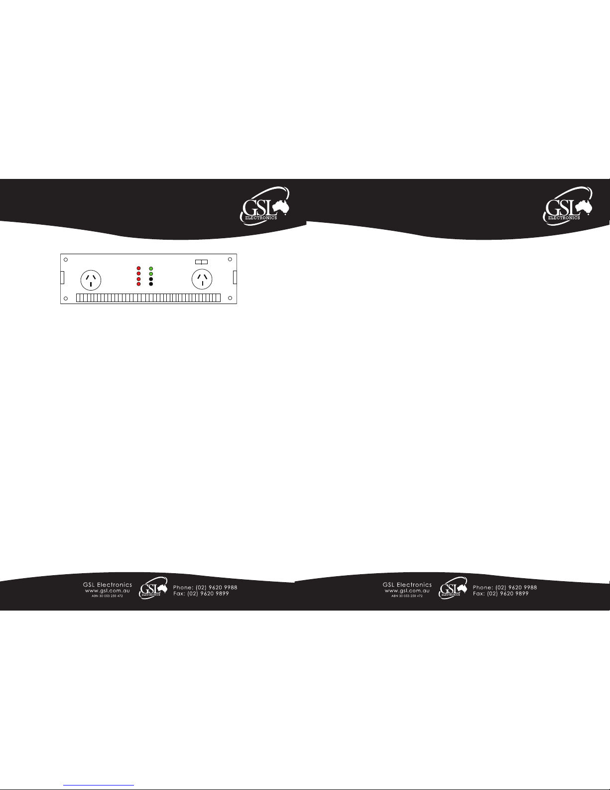
1. Controls and indicators (All models):
The ON/OFF switch turns the control circuit in the power inverter on and off. It does not disconnect power from the
power inverter.
2. Over voltage indicator (except SW150):
The over voltage LED indicates that the power inverter has shut itself down because its input voltage higher than the
operating voltage.
3. Under voltage indicator (except SW150):
The under voltage LED indicates that the power inverter has shut itself down because its input voltage is lower than
operating voltage.
4. Over temp indicator (except SW150):
The over temp LED indicates that the power inverter has shut down because it has become overheated (75°C). The
power inverter may overheat because it has been operated at power levels above it’s rating, or because it has been
installed in a location, which does not allow it to dissipate heat properly. The power inverter will restart automatically
once it has cooled off.
5. Overload indicator (except SW150):
The overload LED indicates that the power inverter has shut itself down because its output circuit has been short
circuited or drastically overloaded. Switch the ON/OFF switch to OFF, correct the fault condition, and then switch the
ON/OFF switch back to ON.
Installation
1. Where to install - The power inverter should be installed in a location that meets the following requirements:
Dry – Do not allow water to drip or splash on the inverter and in an area free of salt or moisture-laden air.
Temperature – Ambient air temperature should be between 0º and 40º.
Ventilation – Allow at least twenty-five millimeters / one inch of clearance around the inverter for airflow. Ensure the
ventilation openings on the rear and bottom of the unit are not obstructed. The installation site should not be susceptible
to temperatures in excess of 50ºC.
Safety – Do not install in a battery compartment or other areas where flammable fumes may exist, such as fuel storage
or engine compartments.
Dust-free – Do not install the inverter in an environment where there are dust, wood particles, metal filings and
shavings. These can be pulled into the unit blocking the cooling fans.
Close to battery / batteries – Avoid excessive cable lengths (Mount the inverter between one and two metres from
the batteries) but do not install the inverter over or in the same compartment as batteries. Use the recommended wire
lengths and sizes. Do not mount the inverter where it will be exposed to the gases produced by the battery. These gases
are very corrosive and prolonged exposure will damage the inverter.
SW240R-R1
Model:
SW150-12, SW650-24
SW350-12, SW1200-24
SW650-12, SW1800-24
SW1200-12, SW3000-24
SW1800-12, SW3000-12
Traveller Series
GSL Electronics
Sine Wave Inverter
Overload
Over Temp
Under Volt
Over Volt
Power
Run
OFF
ON
Front view, main functions & Operation:
Page 3 of 4
Unit 2, 110 Station Road, Seven Hills ,NSW, 2147, Australia
Traveller Series
240VAC Sine Wave Power Inverter
Operating Instructions
Please read these instructions before use
SW240R-R1
Model:
SW150-12, SW650-24
SW350-12, SW1200-24
SW650-12, SW1800-24
SW1200-12, SW3000-24
SW1800-12, SW3000-12
2. Making DC Wiring Connections: Follow this procedure to connect the battery cables to the DC input terminals on the
inverter. Your cables should be as short as possible (ideally, less than 10 feet / 3 metres).
a. Unpack and inspect the power inverter, check to see that the power switch in the OFF position.
b. Connect the DC POSITIVE cable to the Positive (POS+) terminal on the battery.
c. Connect the cable to the Positive terminal on the inverter.
d. Connect the DC NEGATIVE cable to the Negative terminal on the inverter.
e. Connect the cable to the Negative (NEG-) terminal of the battery. This should be the last connection made. A spark
when making this final connection is normal.
CAUTION! - Reversed polarity connections will blow a fuse in inverter and may permanently damage the inverter.
Damage caused by a reverse polarity connection is not covered by our warranty.
WARNING! - You may observe a spark when you make this connection. Do not make this connection in
the presence of flammable fumes. Explosion or fire may result.
WARNING! - Make sure all the DC connections are tight. Loose connections will overheat and could
result in a fire hazard.
Testing Unit after Connection:
1. Set the power switch to the ON position. Check the POWER and RUN (flashes when in Stand By mode) indicators
on the front panel of the inverter. If the LED is not lit, check the power source and the connections to inverter. The other
indicators should be off.
2. Set power inverter switch to the OFF position. The indicator lights may blink and the internal alarm may sound
momentarily. Plug the test load into the AC receptacle on the front panel of the inverter. Leave the test load switch off.
3. Set power inverter switch to the ON position and turn the test load on. The inverter should supply power to the load.
4. If you are operating several loads from the power inverter, switch them on separately after the inverter has been
switched on.
Auto Load Sensing (SW650, SW1200, SW1800, SW3000):
Our inverter features automatic load sensing, allowing the inverter to wait in Standby mode until an AC load is switched
ON. When an AC load appears the inverter will start immediately. This feature conserves valuable battery energy as the
inverter uses only about 10% of normal power when in standby mode (standby is indicated by flashing green lamp).
Maintenance:
Helpful Tip to Conserve Battery Power
Should the inverter not be used over an extended period of time, it is recommended that the battery be disconnected
from the inverter. This will ensure battery will not be drained over the period of non-usage.
Very little maintenance is required to keep your inverter operating properly. You should clean the exterior of the unit
periodically with a damp cloth to prevent accumulation of dust and dirt. At the same time, tighten the screws on the DC
input terminals.
WARNING!
Do not open or disassemble inverter. Attempting to service the unit yourself may result in a risk of electrical shock or fire.
 Loading...