

Page 1 of 4
Model:
NGBC1222
Unit 2, 110 Station Road, Seven Hills ,NSW, 2147, Australia
12 Volt
DC-DC Voltage Booster Battery Charger
Operating Instructions
Please read these instructions before use
NGBC-R3
Operation Guide
Thank You for purchasing another quality GSL Product. This Micro Controlled Booster Charger has been designed to
overcome the limitations of most auxiliary charging systems.
The NGBC1222 is a Next Generation full 3 stage 22Amp Charger which will operate from voltages as low as 11.5Volts up
to 15.5Volts whilst still providing optimal charge to a variety of lead acid and lithium battery chemistries. Feature rich unit
incorporates revolutionary new concepts in battery charging.
Featuring:
Optional:
• Automatic Start Assist - Using a solenoid (Sold Separately on NGBC1222-1) will automatically jumpstart from an axilliary battery.
• Constant Output Power Limiting - Giving you more charging current when auxilliary battery is low (Up to 25A output)
• Thermal Compensation - Via optional external LM series sensor. (For Lead Based Batteries Only)
• Automatic voltage drop compensation - calculates and overcomes voltage drop on long wire runs.
• Polymer Encapsulation - Weatherproof convection cooled aluminum construction.
• High Operating Temperatures - Safely work up to 70°C. Full power output to 45°C with gradual power degrading to 70°C
NGBC1222
Page 2 of 4
Model:
NGBC1222
Unit 2, 110 Station Road, Seven Hills ,NSW, 2147, Australia
12 Volt
DC-DC Voltage Booster Battery Charger
Operating Instructions
Please read these instructions before use
NGBC-R3
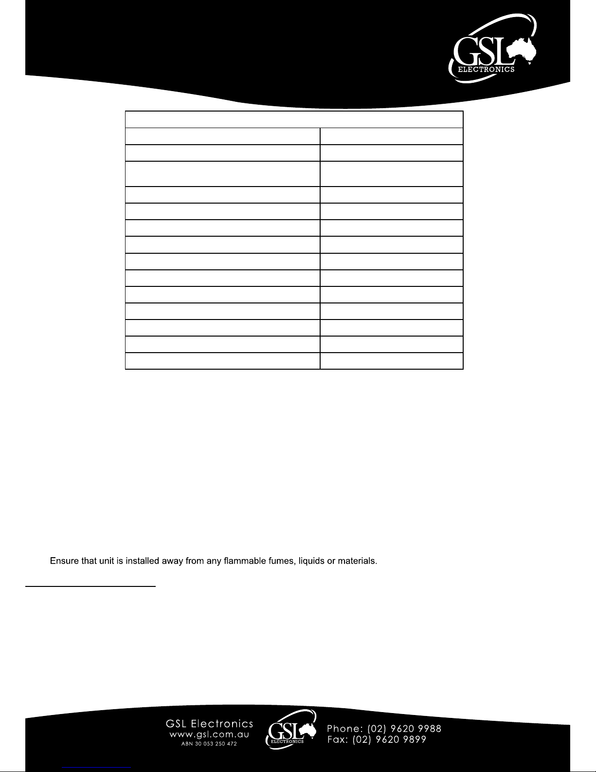
Operational Parameters
Maximum Current at Bulk Charge 22Amps
Input Operating Voltage Range 11.5V to 15.5Volts
Maximum Charge Voltage for Flooded Cell (LEAD
ACID)
14.6Volts
Maximum Charge Voltage for Lithium 14.4Volts
Maximum Charge Voltage for AGM/GEL 14.2Volts
Float Voltage 13.5Volts
Lithium Maintenance Charge 13.2V
Standby Current 0.003A
Maximium Charge Current With Low Auxiliary 25A
Maximum Operating Temperature 70°C
Automatic Derating Above 45°C 0.7A/°C
Temperature Compensation 0.25%/°C
Dimensions 162mm(L) x 71.5mm(W) x 32.2mm(H)
Weight 560g
The remote LED indicator can be installed where it will provide a simple visual indication of the system status.
The LED anode (+) should be connected to the YELLOW wire and the cathode (-) to the vehicle chassis or the battery negative.
ON : Auxiliary battery charging
Flashing : Auxiliary battery charging at low voltage
Blinking : Automatic Start Assist operated. This is a latched alarm indicating that there is a serious issue with the main battery or
cabling. Please check your main battery for issues. Refer to Automatic Start Assist section for more information.
To reset from latched alarm: the ignition is required to be turned off and on.
OFF: Unit not working or not in operation.
LED Indicators Guide
Notes:
• Before installation the user shall determine the suitability of the product to ensure correct application.
• Check with your battery manufacturer for the suitablity of the charger for your installation.
• Where Lithium battery banks are invovled ensure your BMS system is compatible with our charger.
• A large spark can sometimes be generated during connection, due to the current required to charge the capacitors in the
charger.
• Do not short output when enabled and operational as this may cause damage to the unit.
The following connection sequence is to be followed: Ground (BLACK), Input (RED), Output (BROWN), Chemistry
(ORANGE) & Control (BLUE).
1. Disconnect the battery supply.
2. Choose a mounting position - Select a position with good ventilation where air can pass freely around the unit.
3. Avoid locations such as fuel lines or where external heat is produced e.g. exhaust system or where the batteries are
located.
4.

Page 3 of 4
Model:
NGBC1222
Unit 2, 110 Station Road, Seven Hills ,NSW, 2147, Australia
12 Volt
DC-DC Voltage Booster Battery Charger
Operating Instructions
Please read these instructions before use
NGBC-R3
To ignition switch of vehicle
RED
BLACK
BROWN
FUSE
30A
ORANGE
YELLOW
Status LED*
BLUE
Chemistry Selection
Fig. 1 BASIC SETUP
Choose a cable size suitable for
your situation.
We recomend 6mm2 cable to be
used up to 10M for RED, BLACK
& BROWN.
Over 10M a larger diameter cable
must be used.
Important: BLACK/Earth
must be securely connected to
permanent earth e.g vehicle body
Fig. 2 REMOTE SETUP
(Where ignition source is not
available at installation)
Choose a cable size suitable for
your situation.
We recomend 6mm
2
cable to be
used up to 10M for RED, BLACK
& BROWN.
Over 10M a larger diameter cable
must be used.
Important: BLACK/Earth
must be securely connected to
permanent earth e.g vehicle body
Solenoid or Relay must be
capable of switching at least
30A DC.
RED
BLACK
BROWN
FUSE
30A
ORANGE
YELLOW
Status LED*
BLUE
Solenoid
Chemistry Selection
To ignition switch
of vehicle.

Page 4 of 4
Model:
NGBC1222
Unit 2, 110 Station Road, Seven Hills ,NSW, 2147, Australia
12 Volt
DC-DC Voltage Booster Battery Charger
Operating Instructions
Please read these instructions before use
NGBC-R3
Fig. 3 Automatic Start Assist
Follow connections for ORANGE, BLUE & YELLOW as per Fig.1 or Fig.2 where
applicable.
Important: If Optional Start Assist Pack is not purchased with kit then
make sure that the solenoid is capable of at least 100A.
Cabling used in the start assist bypass (ASSIST Wire and RED) will
need to be suitable for high current stresses for starting the vehicle.
This optional extra enables the automatic use of the energy stored in the auxiliary battery to start a vehicle with a faulty or
discharged main battery.
When using this option a high current solenoid is activated for approx. 30 seconds following an ignition attempt where the main
battery drops below 7V.
, and no auxiliary
battery charge will take place, to insure the main battery is replenished as soon as possible, until the next ignition attempt.
Temperature Compensation :
Temperature compensation of the battery charging voltage extends the battery life and improves the charging process.
Fixed charging voltage can result in either undercharging the battery at low temperatures or overcharging it at high temperatures.
of the battery operating temperature.
The NGBC1222 applies a small negative coefficent to the programmed voltage (Approx. -5mV/°C) to compensate for the variation
Attach supplied Thermal sensor to the smaller Black and Red wires (Not the Main and Auxiliary wires) and mount the sensor near
the battery to measure ambient temperatures at the charging/auxilary battery
.
(This feature is for lead based chemistries only.)
Warranty Conditions: Our products come with guarantees that cannot be excluded under the Australian Consumer Law.
The customer is entitled to a replacement or refund for a major failure and compensation for any other reasonably foreseeable loss or damage.
The customer is also entitled to have the products repaired or replaced if the products fail to be of acceptable quality and the failure does not amount to a major failure.
GSL Electronics (GSL) warrants that its products will, under normal use and service, be free of defects in material and workmanship for a period of two (2) years from
the date of the original purchase by the customer as marked on the customer’s original invoice.
Please refer to our website for full warranty and return information which can be found at http://www.gsl.com.au/faq.html
Automatic Start Assist:
RED
GREEN
BLACK
BROWN
ASSIST Wire
FUSE
30A
If the temperature compensation is not required then simply cut the wires to the thermal sensor to avoid abnormal charging.
 Loading...