

Page 1 of 8
Model:
MPPT30HV
Unit 2, 110 Station Road, Seven Hills ,NSW, 2147, Australia
Operating Instructions
Please read these instructions before use
This revolutionary maximum power point tracker solar charger was designed
using the technology that won GSL Electronics the prestigious “2008 EDN
Innovation award”. A simple, compact and low cost alternative. Ideal for
charging batteries with the new low cost and high efciency grid type panels.
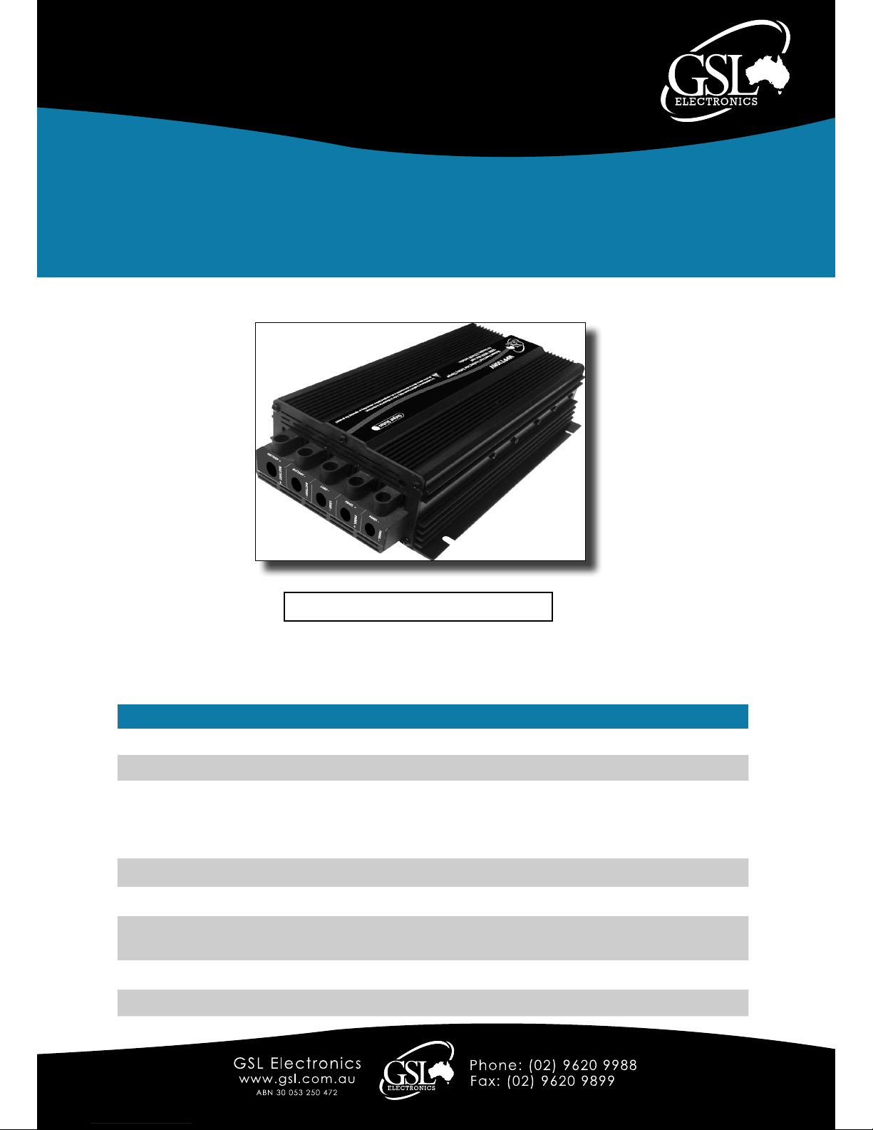
MPPT30HV Unit
1800W Solar Battery Charger
Maximum Power Point Tracker
MPPT30HV Specications
Efciency typical 97%
Input voltage 16V to 180V
Output voltage
Float - 13.5V / 27V / 54V
Absorption - Vented LA batteries 14.5V / 29V / 58V
Sealed LA batteries 14.2V / 28.4V / 56.8V
Calcium Batteries 15V / 30V / 60V
Output power 1800W / 30A MAX
Quiescent current 0.05A
Thermal protection Automatic output derating to 70°C
Dimensions (mm) 306 X 177 X 70mm
Indications LED display – OUTPUT STATUS
MPPT30HV-R5
PATENT APPLIED FOR - 2010901565
The MPPT is designed to charge sealed and vented lead acid batteries from photovoltaic pannels.
Silicon based panels such as monocrystalline, polycrystalline and amorphous are suitable.

Page 2 of 8
Model:
MPPT30HV
1800W Solar Battery Charger
Maximum Power Point Tracker
Operating Instructions
Please read these instructions before use
Unit 2, 110 Station Road, Seven Hills ,NSW, 2147, Australia
MPPT30HV-R5
Important notes:
• Only qualied electricians or technicians who are familiar with solar system design and wiring
practices should install this product.
• Use only PV Systems with open circuit voltage below 180V and a minimumV
MP
of 16V for 12V
batteries, 32V for 24V batteries and 64V for 48V batteries.
•This equipment must be installed by qualied personnel only and incorrect wiring can cause
re, injury or death – GSL will accept no responsibility for MPPT misconnection or misuse.
• Use only sealed, vented or calcium 12V, 24V or 48V lead acid batteries and conrm the MPPT
settings charge voltages and currents are correct for your battery system – if in any doubt seek
qualied advice!
• Use wires suitable for at least 40A, but if wire runs are over 3m then larger wires are
recommended to limit voltage drop and losses.
• Install the unit in a dry place out of direct sunlight and away from ammable liquids or gases.
• The MPPT preferred mounting position is vertical with the fan on the lower side and at least 50mm
clearances on top and bottom.
• Battery fuse ( BF ) is always required and must be located as close to the battery as possible,
its sizing depends on the wire size and load ratings. (Always use DC fuses rated to match your
batteries and charging situation.)
• Before connecting the battery always check the battery and PV panel polarity.
• The MPPT30HV chassis must be properly earthed - if in any doubt seek qualied advice!
(We Recommend at least one of the one of the mounting xtures is tted with an external star
washer against the heatsink.)
• Make sure that if the electrical circuit requires grounding that it is only grounded in one point.
Ground on multiple points, such as on PV and Battery, may compromise MPPT Protections.
• Make Sure that the connection sequence is as follows. 1st “Panel -”, 2nd “Panel +”,
3rd “Battery -”, 4th “Battery +” and nally 5th “Load -”
MPPT30HV General Information:
• Green LED On – Battery voltage above nominal.
• Green LED Flashing – Battery voltage below nominal.
• This MPPT is designed to auto detect 12V, 24V or 48V battery systems.
• The MPPT30HV is shipped in a sealed battery setting. But if your batteries are vented or
calcium then, BEFORE wiring the MPPT in, follow the CHANGING BATTERY TYPE
SETTING PROCEDURE.
• This MPPT has an automatic output power derating to 70°C to improve product reliability
while maximising output power availability.
• The maximum continuous output power is 1800W in 48V systems, 900W in 24V systems
and 450W in 12V systems. The output current is limited to 30A.\
• For additional safety and reliability we recommend the MPPT30HV to be used in
conjunction with the MIHV240.
Page 3 of 8
Model:
MPPT30HV
Unit 2, 110 Station Road, Seven Hills ,NSW, 2147, Australia
Operating Instructions
Please read these instructions before use
1800W Solar Battery Charger
Maximum Power Point Tracker
MPPT30HV-R5
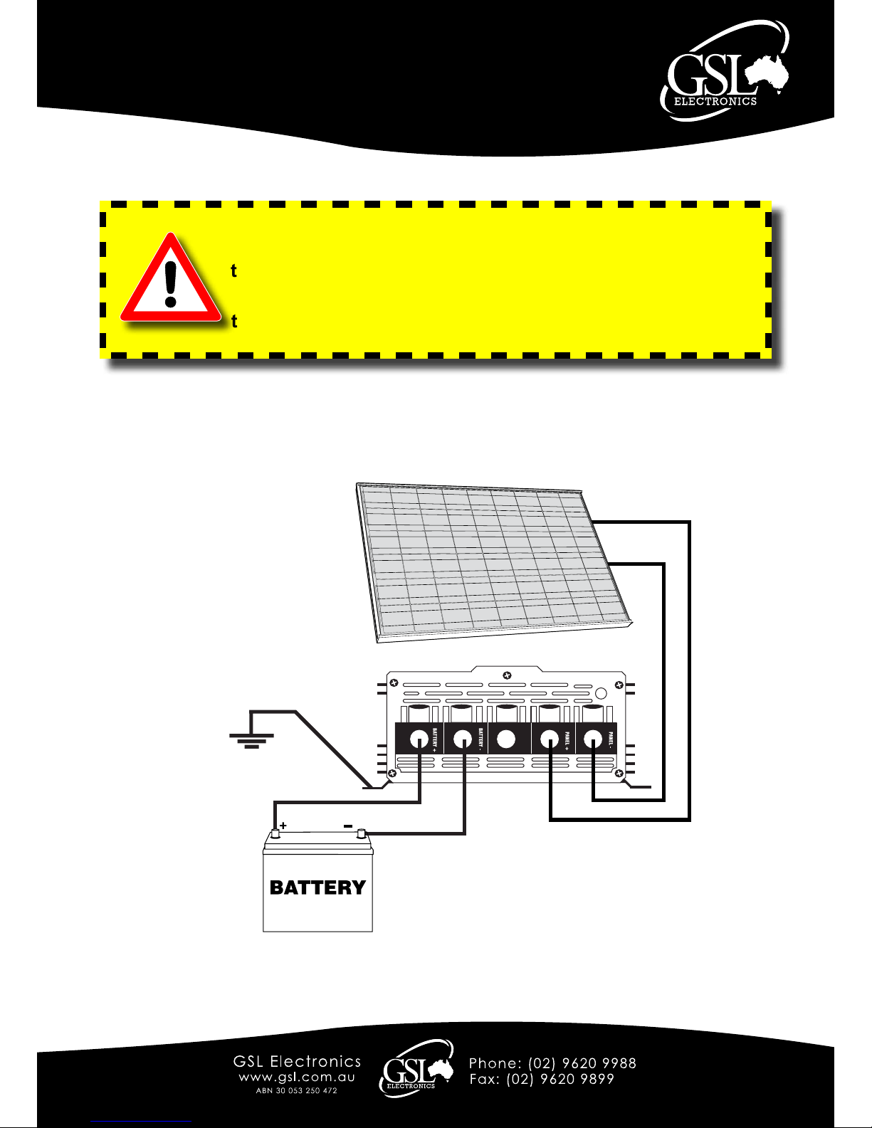
Basic Wiring Instructions:
For saftey the chassis must be earthed.
Panel +
Panel -
Battery +
Battery -
All power sources, including panels and batteries, must be
disconnected or de-energised before installing or opening
this product.
For saftey the chassis must be earthed. If in doubt about
the earthing or connections seek qualied advice!
Page 4 of 8
Model:
MPPT30HV
Operating Instructions
Please read these instructions before use
Unit 2, 110 Station Road, Seven Hills ,NSW, 2147, Australia
1800W Solar Battery Charger
Maximum Power Point Tracker
MPPT30HV-R5
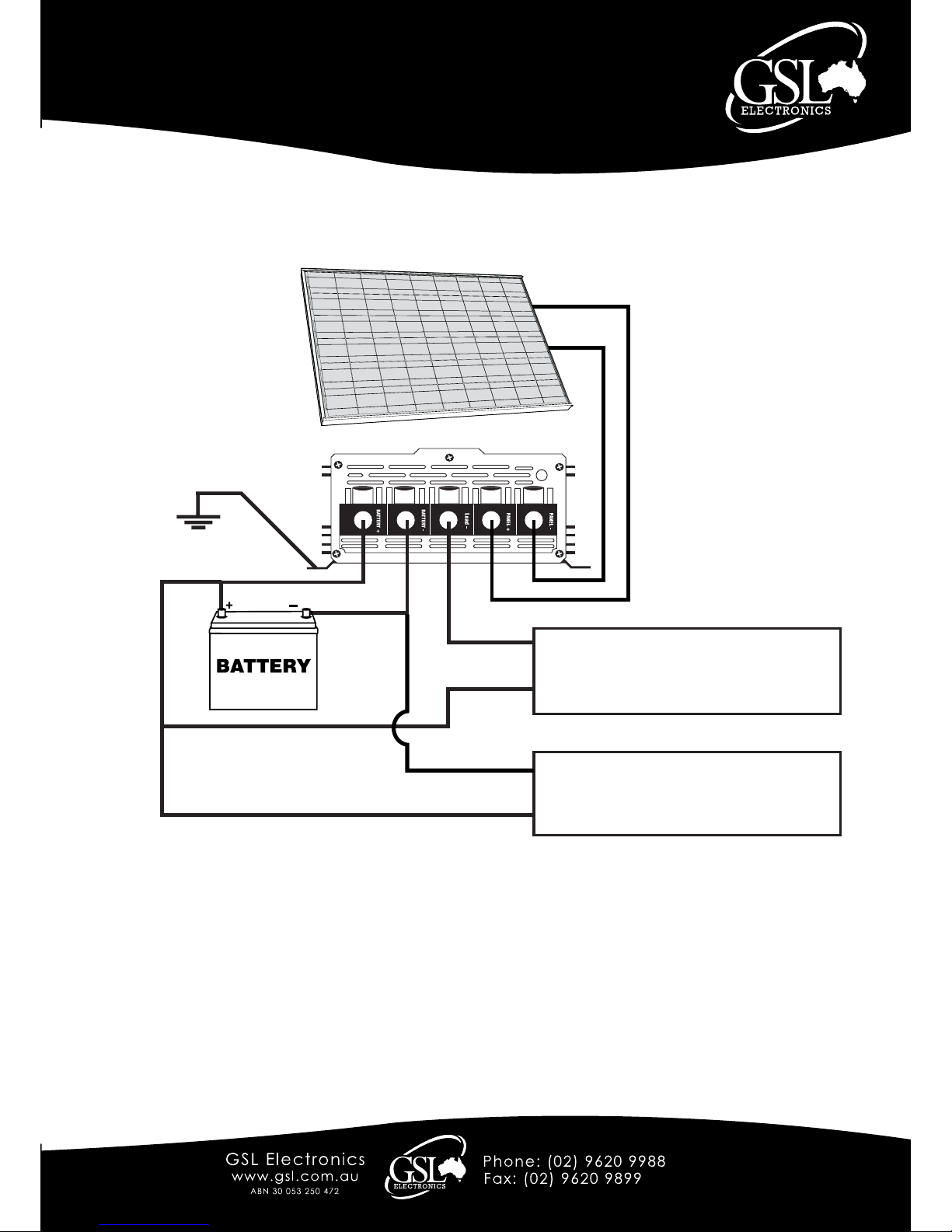
Panel +
Panel -
Battery +
Battery -
Non Critical Load
To be controled via MPPT’s inbult
Low Voltage Disconnect / Dawn to Dusk /Load Control
Critical Load
Caution : Assess yor own needs of these loads over
the protection of your battery.
Battery+
Battery+
Battery -
Load -
Load Wiring Instructions:
All power sources, including
panels and batteries, must
be disconnected or
de-energised before
installing or opening this
product.
For saftey the chassis
must be earthed.
Wiring with MCM option:
Connecting the optional MCM-30 to the MPPT will allow various system parameter displays,
output voltage and alarm settings and enable the programmable dawn to dusk or remote load
control options.
The 9-pin D-Sub connector for the MCM is located at the rear of the unit
For full connection details please refer to MCM Manual.

Page 5 of 8
Model:
MPPT30HV
Unit 2, 110 Station Road, Seven Hills ,NSW, 2147, Australia
Operating Instructions
Please read these instructions before use
1800W Solar Battery Charger
Maximum Power Point Tracker
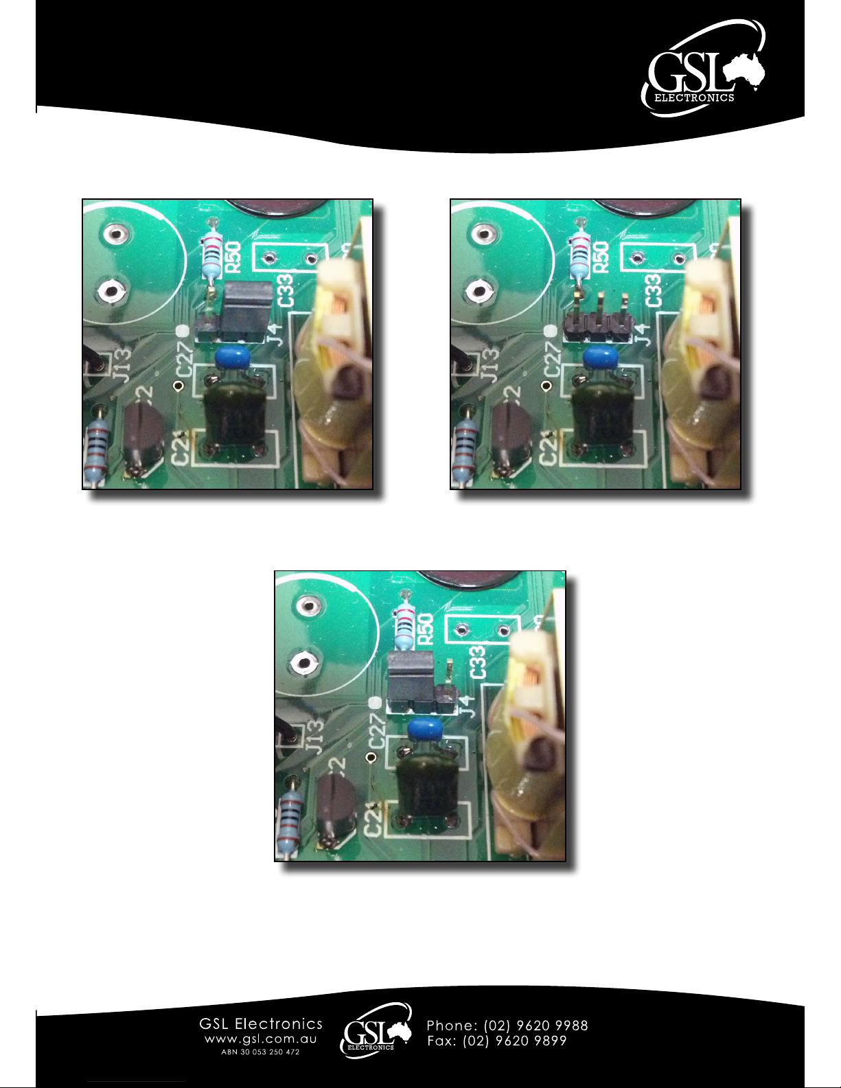
Changing Battery Type Setting Procedure
1.Ensure all the MPPT wires are disconnected.
2.Remove 7 front panel screws and the front panel and slide out cover – see Figure 1.
3.Locate connector J4 – see Figure 1.
4.Shift link on J4 to desired position – see Figure 2 , 3 or 4.
5.Slide back cover and t in front panel carefully, insuring led ts properly into housing,
and screw back the 7 mounting screws.
• The above procedure can be repeated to change to a different mode.
Figure 1.
MPPT30HV-R5
Page 6 of 8
Model:
MPPT30HV
Operating Instructions
Please read these instructions before use
Unit 2, 110 Station Road, Seven Hills ,NSW, 2147, Australia
1800W Solar Battery Charger
Maximum Power Point Tracker
Figure 2 (Above): Vented Battery Setting
Figure 3 (Above): Calcium Battery Setting
Figure 4 (Above): Sealed Battery Setting
MPPT30HV-R5

Page 7 of 8
Model:
MPPT30HV
Unit 2, 110 Station Road, Seven Hills ,NSW, 2147, Australia
Operating Instructions
Please read these instructions before use
1800W Solar Battery Charger
Maximum Power Point Tracker
MPPT FAQs
Q: What is an MPPT?
MPPT stands for Maximum Power Point Tracker and is a specialized converter designed to
maintain the PV voltage at the level in which it delivers maximum power to the load or battery.
The panel’s nominal output power can only be obtained with the use of an MPPT.
Q: What are the GSL MPPT’s advantages compared to standard solar regulators?
1. Suitable for lower cost non battery type PV since the MPPT can efciently charge the
batteries from relatively high voltage, say 24V batteries from 40V MPP panels.
2. Less interference and more accurate voltages during absorption and oat.
Q: What sorts of loads can I power with the MPPT30HV?
1.The maximum bulk charge current with the MPPT30HV on a 12V battery and 400W panel
is approximately 30A, so you can expect about 100AH per day which means a 100W load
for about 10 hours daily.
2. Following the same reasoning with a 24V 800W panel the MPPT30HV will supply a daily
load of 200W for about 10 hours.
3. Following the same reasoning with a 48V 1600W panel the MPPT30HV will supply a daily
load of 400W for about 10 hours.
Q: Why are MPPT not more common in standalone solar systems?
Until now and despite their overwhelming advantages MPPTs have not been commonly used
in standalone solar systems because of cost. The new GSL MPPT specically addresses this
issue making economic sense in a wide range of solar systems.
Q: What sort of batteries should I use?
1. A deep cycle battery is a must due to the cyclical nature of the solar system with a
recommended battery capacity of at least a few days of running your load.
2. A larger battery will not only give longer run time during low light but also will be able to
avoid available PV power being unstored such as when battery reaches the oat stage.
Q: How do PV temperatures affects charge current?
Temperature increase brings down the PVs maximum power point voltage reducing the
MPPTs current gain available. In principle at 25C it is possible to achieve 30% gain but at
40C, a more realistic average temperature, about 20% is still available.
Q: What happens at low PV currents?
The MPPT will outperform the conventional regulator above 3% of nominal panel power.
Below 3%, about 10W in a 400W panel, the MPPT will have a slightly lower output current
than a non MPPT.
MPPT30HV-R5

Page 8 of 8
Model:
MPPT30HV
Operating Instructions
Please read these instructions before use
Unit 2, 110 Station Road, Seven Hills ,NSW, 2147, Australia
1800W Solar Battery Charger
Maximum Power Point Tracker
Q: Is interference possible? and If so what do I do?
GSL’s MPPTs produce far less interference than conventional solar regulator during
the absorption and oat stages, that is during most of its operating time, and its
designed to comply with local and international EMI standards however some
interference is still possible. If interference occurs rst try and reorient the aerial or move
the sensitive equipment away from the MPPT wires. Ensure the MPPT chassis is grounded.
Grounding a battery terminal (but only ground one point in cirucit do not ground both input and
output) may also help and nally you can try adding ferrite clamps.
MPPT30HV-R5
Visit our website
www.gsl.com.au
For our complete range of Products and Information
Warranty Conditions: Our products come with guarantees that cannot be excluded under the Australian Consumer Law.
The customer is entitled to a replacement or refund for a major failure and compensation for any other reasonably foreseeable loss
or damage.
The customer is also entitled to have the products repaired or replaced if the products fail to be of acceptable quality and the
failure does not amount to a major failure.
GSL Electronics (GSL) warrants that its products will, under normal use and service, be free of defects in material and
workmanship for a period of two (2) years from the date of the original purchase by the customer as marked on the customer’s
original invoice.
Please refer to our website for full warranty and return information which can be found at http://www.gsl.com.au/faq.html
 Loading...