

MPPT12-1-R5
Page 1 of 4
Model:
MPPT12-1
Unit 2, 110 Station Road, Seven Hills ,NSW, 2147, Australia
200W Solar Charger
Maximum Power Point Tracker
Operating Instructions
Please read these instructions before use
This revolutionary maximum power point tracker solar charger was
designed using the technology that won GSL Electronics the prestigious
“2008 EDN Innovation award”. A simple, compact and low cost
alternative. Ideal for charging batteries with the new low cost and high
efciency grid type panels.
Important:
• Use only PV Systems with open circuit voltage below 55V and a V
MP
no less than 17V for 12V Charging
and 34V for 24V Charging.
• Use wires suitable for at least 15a, but if wire runs are over 3m then larger wires are recommended to
limit voltage drop and losses.
• Install the unit in a dry place out of direct sunlight and away from ammable liquids or gases.
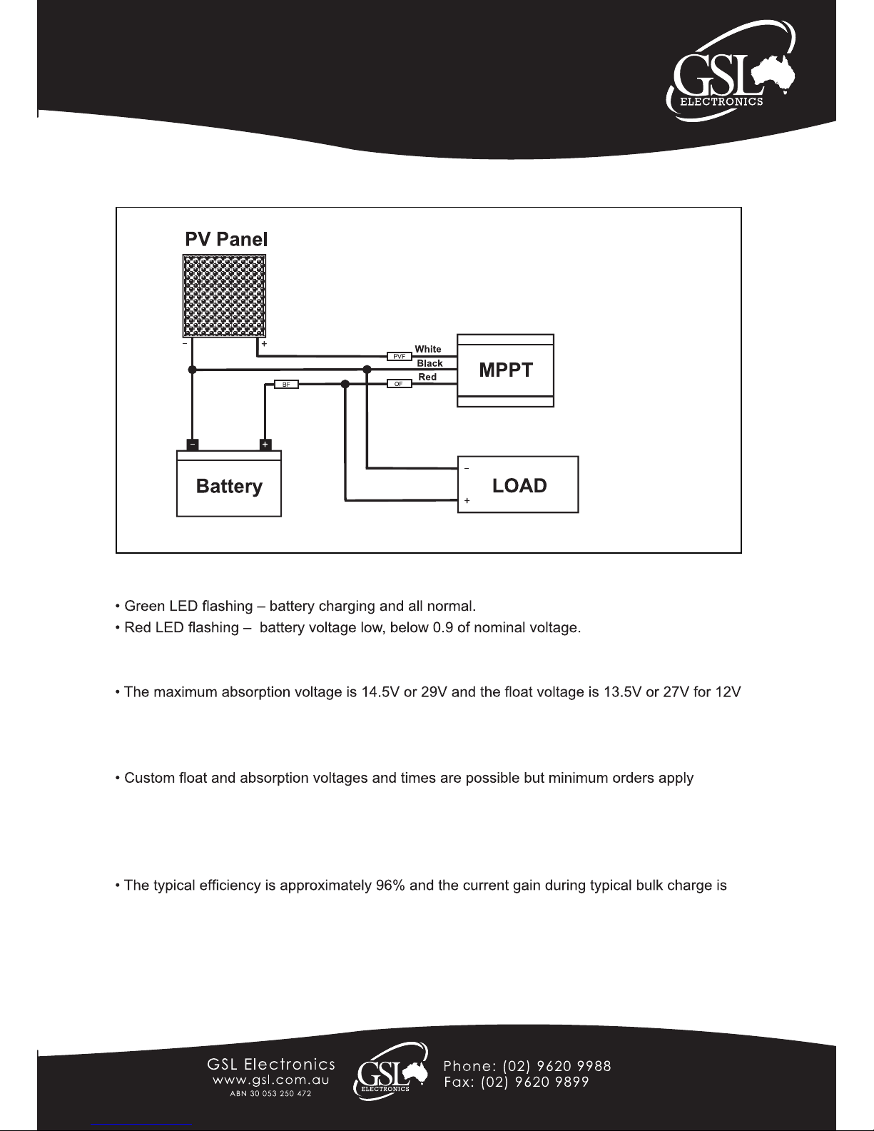
• Battery fuse ( BF ) is always required and must be located as close to the battery as possible, its sizing
depends on the wire size and load ratings. Typically a 15A 24V fuse would do.
• Locate the PV fuse (PVF) as close to the MPPT as possible (10A 60VDC Rating). PVF only mandatory
with high power panels.
• If used, this fuse is optional, locate the output fuse (of) as close to the MPPT as possible
(15A 24VDC rating).
• Before connecting battery always check battery and PV panel polarity.
MPPT12-1 Unit
PATENT APPLIED FOR - 2010901565
Page 2 of 4
Model:
MPPT12-1
200W Solar Charger
Maximum Power Point Tracker
Operating Instructions
Please read these instructions before use
Unit 2, 110 Station Road, Seven Hills ,NSW, 2147, Australia
Basic Wiring Instructions:
MPPT12-1 General Information:
• This MPPT is designed to auto detect 12V and 24V battery systems and select a suitable
charge regime.
or 24V batteries respectively.
• The absorption phase is entered following a low battery condition and is maintained for
approx. 1.5 hours.
.
• This MPPT has a built in multilevel over temperature protection to improve product reliability
while maximising output power availability.
• The peak maximum output power is 250W and the continuous output power is 150W on 12V
systems and 200W on 24V.
over 20%.
• The fuse PVF can be replaced by a suitably heatsinked 20A 60V schottky diode ( its anode
connected to the + panel and cathode to the MPPT white wire). This diode will avoid a small
drain during night time (approx. 0.04A ) as well as protect against panel short but it will also
slightly decrease the battery charge current.
Note: First start up may take up to one minute.
MPPT12-1-R5

Page 3 of 4
Model:
MPPT12-1
Unit 2, 110 Station Road, Seven Hills ,NSW, 2147, Australia
200W Solar Charger
Maximum Power Point Tracker
Operating Instructions
Please read these instructions before use
MPPT FAQs
Q: What is an MPPT?
MPPT stands for Maximum Power Point Tracker and is a specialized converter designed to
maintain the PV voltage at the level in which it delivers maximum power to the load or battery.
The nominal panel output power can only be ensured with the use of an MPPT.
Q: What are the GSL MPPTs advantages compared to standard solar regulators?
1. Suitable for new lower cost high efciency grid type panels since the GSL MPPT can efciently
charge the batteries from relatively high voltage, say 12V batteries from 36V MPP panels.
2. Less interference and more accurate voltages during absorption and oat.
Q: What output can I expect from a 150W or 200W MPPT?
1. The maximum bulk charge current with 12V battery and 150W panel is approximately 12A, so
you can expect about 40AH per day which is a 40W load for about 10 hours.
2. The maximum bulk charge current with a 24V battery and a 200W panel is about 8A so you
can expect about 30AH which is a 40W load for about 15 hours.
Q: Why are MPPT used mainly in high power systems?
Until now and despite their overwhelming advantages MPPTs have been excluded from low
power systems because of cost. The new GSL MPPT specically designed for low power makes
economic sense even in small systems.
Q: What sort of batteries should I use?
1. A deep cycle battery is a must due to the cyclical nature of the solar system with a
• The MPPT12-1 will efciently charge 12V batteries from 24V panels.
• The panel voltage limits for the MPPT12-1 are: Maximum open circuit voltage below 55V.
• Minimum Maximum Power Point ( at the maximum operating temperature) must be above 17V
for 12V batteries and 32V for 24V batteries to ensure full power.
• When used with panels over 150W @ 12V or 200W @ 24V the MPPT12-1 MUST be tted
with the PVF fuse.
For optimal power output the following panel combinations are recomended:-
12V Charging
• 2 x 12V Battery Panels connected in series (Total VOC =42V & VMP =32V)
• 1 x 24V Battery Panel (Total VOC =42V & VMP =32V)
• 1 x 48 Cell Grid Panel (Total VOC =28V & VMP =23V)
• 1 x 54 Cell Grid Panel (Total VOC =32V & VMP =26V)
• 1 x 52 Cell Grid Panel (Total VOC =31V & VMP =25V)
• 1 x 60 Cell Grid Panel (Total VOC =36V & VMP =29V)
• 1 x 72 Cell Grid Panel (Total VOC =44V & VMP =36V)
24V Charging
• 1 x 72 Cell Grid Panel (Total VOC =44V & VMP =36V)
MPPT12-1-R5

Page 4 of 4
Model:
MPPT12-1
200W Solar Charger
Maximum Power Point Tracker
Operating Instructions
Please read these instructions before use
Warranty Conditions: The product is warranted to be free from defects in materials and workmanship under normal use and
service for a period of 24 months from the date of sale. This warranty covers defective parts and workmanship provided that
the product is shipped prepaid to the seller within 24 months of purchase of goods. This warranty is limited to the repair or
replacement (at the manufacturers’ discretion) of parts and shipping prepaid to the original despatch destination. We regret that
no liability can be accepted for consequential or special damages of any kind howsoever arising in connection with products
supplied by the seller. This warranty is in lieu of all other warranties expressed or implied. No representative is authorised to
assume for the seller any other liability in connection with the seller’s products.
MPPT12-1 Specications
Efciency typical 96%
Input voltage 16V to 55V
Output voltage Float 13.5V / 27V Absorption 14.5V / 29V
Output power Peak 250W, constant 200W @29V / 150W @ 14.5V
Quiescent current 0.04A
Thermal protection Multilevel type
Dimensions (mm) 35 X 75 X 100mm
Indications Dual LED display – battery OK / LOW
Unit 2, 110 Station Road, Seven Hills ,NSW, 2147, Australia
recommended battery capacity of at least 60AH.
2. A larger battery will not only give longer run time during low light but also will be able to
avoid available PV power being unstored such as when battery reaches the oat stage.
Q: How does PV temperatures affects charge current?
Temperature increase brings down the PVs maximum power point voltage reducing the
MPPTs current gain available. In principle at 25C it is possible to achieve 30% gain but at
40C, a more realistic average temperature, about 20% is still available.
Q: What happens at low PV currents?
The MPPT will outperform the conventional regulator above 4% of nominal panel power.
Below 4%, 6W in a 150W panel, the MPPT will have a slightly lower output current than a
non MPPT.
Q: Is interference possible? and If so what do I do?
GSL’s MPPTs produce far less interference than conventional solar regulator during the
absorption and oat stages, that is during most of its operating time, and its designed
to comply with local and international EMI standards however some interference is still
possible. If interference occurs rst try and reorient the aerial or move the sensitive
equipment away from the MPPT wires. Ensure the MPPT chassis is grounded.
Grounding a battery terminal may also help and nally you can try adding ferrite clamps.
MPPT12-1-R5
 Loading...