

Page 1 of 4
Installation & Operating Instructions
Please read these instructions before use
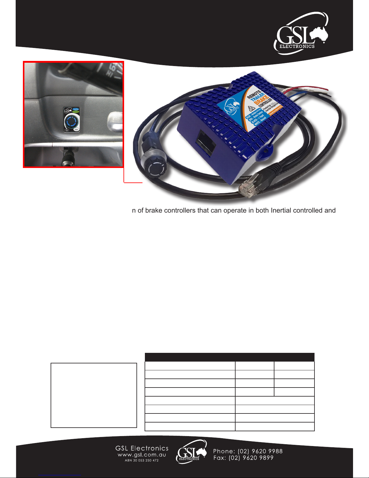
The IRBC range is a new generation of brake controllers that can operate in both Inertial controlled and
Preset brake force utilising microprocessor and Tri-axis Accelerometer technologies. It is a compact,
rugged, electronic brake controller and is easily installed with the connection of four wires and the easy
plug in remote control. Easily adjustable via the remote control which can be located up to 1m from the
controller. Both models also incorporate an over-ride function for manual control.
Designed for both single and dual axle trailers using negative earth (ground) systems only.
Available in 12V & the new 24V version eliminating the need for a separate reducer on 24V systems.
Specications IRBC-12 IRBC-24
Minimum Input Voltage 9 VDC 18 VDC
Nominal Input Voltage 12 VDC 24 VDC
Maximum Input Voltage 15 VDC 30 VDC
Suitable For 12V Trailer Brakes Yes Yes
No Current Load 30 mA
Maximum Load 2 Axle / 12A Avg
Dimensions 30mm x 57mm x 90mm
Weight 200g
Models:
IRBC-12 & IRBC-24
12V and 24V
Remote Brake Controllers
Features :
• LED remote indication for brake connected and brake on.
• Small, easy t single hole dash board mounting Knob with LED built in on 1M of cable tted with a plug to
mate main unit.
• Easy adjustment via knob rotation in remote
• Inertial or PWM selection Via Knob
• Convenient Over-Ride via knob push in remote
• Can Be mounted at Any Angle.
• Compatible with single filament /Brake bulb systems
Product comes with:
1x Retaining Nut ( On Unit )
1x Washer ( On Unit )
1x Control Knob
1x Remote Decal
2x Mounting Screws
(Standard installation)
IRBC -12
IRBC-r3
Unit 2, 110 Station Road, Seven Hills ,NSW, 2147, Australia
Page 1 of 4
Page 2 of 4
Installation & Operating Instructions
Please read these instructions before use
Models:
IRBC-12 & IRBC-24
12V and 24V
Remote Brake Controllers
Installation :
1. Disconnect the vehicle’s NEGATIVE battery terminal.
2. Determine a suitable mounting location inside the cabin. The unit must be mounted securely to a solid
and rigid surface.
3. Hold the main unit in the selected position and mark the hole location through the holes in the anges of
the unit.
4. Using a suitable drill bit, drill holes in the marked locations.
5. Secure Main unit in position with self tapping screws being careful not to strip the holes by
over-tightening.
6. Drill a hole for the 8.5mm Shaft in a suitably sized mounting panel in the dash with a wall thickness of
less than 4mm.
7. Afx decal and locking nut over shaft and tighten. Turn shaft fully counter clockwise and afx the knob
on the shaft with rm even pressure with the indicator facing the minimum position.
8. Plug the RJ45 connector on remote cable into main unit.
9. Connect brake wiring as per wiring instructions and follow Set-up and Operation procedures.
Note : The IRBC-12 and IRBC-24 are load activated and can not be tested without load. At no load, output
reading of high voltage will register. Also the output voltage is PULSED, so it cannot be measured
with a volt meter or test light.
IRBC-r3
Unit 2, 110 Station Road, Seven Hills ,NSW, 2147, Australia
Page 2 of 4
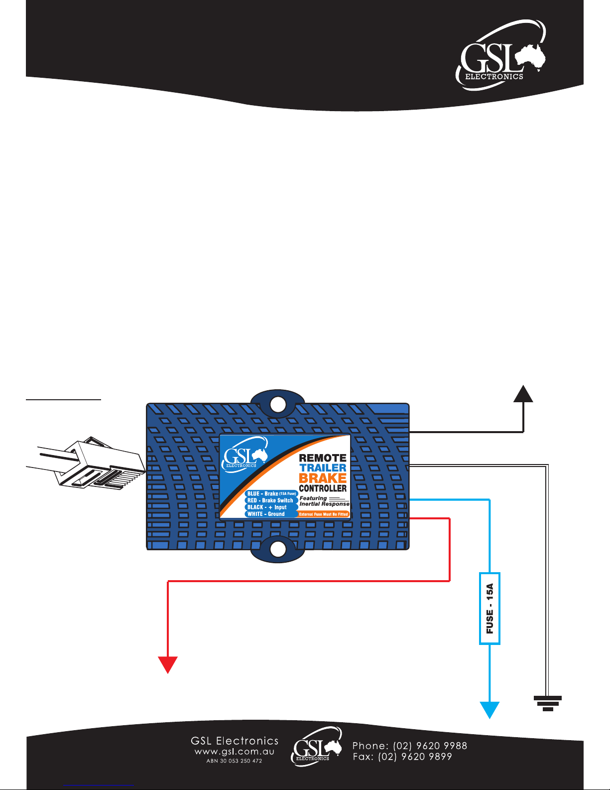
Wiring Diagram
To Remote Control
BLACK
BLUE
WHITE
RED
To Vehicle Brake Switch (Cold Side)
Or source that is pure DC when vehicle brake lights are on.
Note: Only Activated by Positive feed.
Earth
To Trailer Brake Coils.
Fuse must be fitted (Not Supplied)
To Positive Voltage Feed
i.e Battery Positive

IRBC-r3
Unit 2, 110 Station Road, Seven Hills ,NSW, 2147, Australia
Page 3 of 4
In the unlikely event of RF Interference try any of the following tips :
1) Refrain from using the vehicle chassis as a conduit for the earth return for the brake coils. Facilitate a separate
ground wire. (See point 3 below)
2) Mount the brake controller route all cables for the input and output of the brake controller away from antennas
and RF Equipment.
3) Use an as short as possible bilar ( or twisted ) wire to feed the RBC and brake coils ( both active and return ).
4) Add a ferrite clamp over the RED, BLUE, BLACK & WHITE wires.
Wiring: Please ensure that a fuse is tted in the Blue Wire (Brake).
The Brake Controller has four (4) coloured wires, BLACK, RED, BLUE and WHITE:.
The BLACK wire is the positive voltage power supply line.
The RED wire must be connected to a point that receives a DC Voltage equal to that of the supply voltage when the
brakes are on. Generally on most vehicles we recommend strongly to connect the RED wire to the cold side of the
brake light switch. If that is not the case on the vehicle then any point that receives a straight DC voltage, i.e. top
rear tail light, brake light relay or the wire connecting to the stop lights on the trailer plug (NOTE: Vehicles that use
the same globe/supply for rear and tail cannot have the RED wire to the stop light/tail lights directly. Please use the
alternatives listed above.)
The BLUE brake wire must be connected directly to the trailer brake wire.
The WHITE ground wire is connected to a grounded metal part of the dash,vehicle re wall or directly to the negative
battery terminal.
* Please Note: An External Fuse Must Be Fitted (Not Supplied).
Wire Guide
White Wire Negative Battery
Blue Wire
Brake
15A Fuse*
Black Wire Positive Battery
Red Wire Brake Switch
* The Control Unit is Activated by A Positive Feed Brake Switch Only.
(Please check the polarity of your vehicles brake switch before connection)
Important: A brake control unit that is not properly grounded may operate intermittently or not at all.
• Make sure all connections are secure.
• Do not connect the Black “BATTERY” wire to the fuse panel or tie into any accessory wiring.
Connecting to the existing wiring may damage the vehicles wiring and cause trailer brake failure.
• Do not reverse Black “BATTERY” wire and White “GROUND” connections.
Even a momentary incorrect connection can damage the brake control unit.
Page 3 of 4
Installation & Operating Instructions
Please read these instructions before use
Models:
IRBC-12 & IRBC-24
12V and 24V
Remote Brake Controllers

IRBC-r3
Unit 2, 110 Station Road, Seven Hills ,NSW, 2147, Australia
Page 4 of 4
Warranty Conditions: Our products come with guarantees that cannot be excluded under the Australian Consumer Law.
The customer is entitled to a replacement or refund for a major failure and compensation for any other reasonably foreseeable loss or damage.
The customer is also entitled to have the products repaired or replaced if the products fail to be of acceptable quality and the failure does not
amount to a major failure.
GSL Electronics (GSL) warrants that its products will, under normal use and service, be free of defects in material and workmanship for a period
of two (2) years from the date of the original purchase by the customer as marked on the customer’s original invoice.
Please refer to our website for full warranty and return information which can be found at http://www.gsl.com.au/faq.html
Set-up & Operation :
Mode Setting:
The unit can be set to operate on a Preset mode (Green LED on) or Inertia Mode (Blue LED On).
To change mode simply set the knob to minimum ( completely counter clockwise) then push and hold the over-ride button (pushing
the knob in) for about 3 seconds until the LED changes colour.
Note: Changing between Preset Mode and Inertial mode - Braking force on Preset Mode may be slightly different from the Inertial
mode and vice versa. Please adjust the braking force as required by the knob as described below.
Setting the braking force:
To set the brake intensity simply rotate the knob until the required braking level is achieved. A clockwise knob rotation will increase
the braking and a counterclockwise will decrease it.
Using the Over-Ride Feature:
To activate the Over-Ride function simply push on the adjustment knob, releasing the knob disables the function. The braking force
when the Over-Ride is active is still determined by the knob position.
Page 4 of 4
Installation & Operating Instructions
Please read these instructions before use
Models:
IRBC-12 & IRBC-24
12V and 24V
Remote Brake Controllers
Foot Off Brake or Override not Pressed
PWM/Digital Mode - OK
Inertial Mode - OK
Check Brake Circuit
Trailer Connected
Unit Active and OK
Trailer Brake Disconnected
Trailer Brake Disconnected
No Power or Controller Disconnected
Foot On Brake or
Override Pressed
LED Status
GREEN LED
BLUE LED
Flashing
Blue Green
Note: Unit will ash 3-4 times after pressing the brake or using the override then return to solid.
 Loading...