

Page 1

Protek 7830 Manual
Get Pricing & Availability at
ApexWaves.com
Call Today: 1-800-915-6216
Email: sales@apexwaves.com
https://www.apexwaves.com/analyzers/protek/protek-analyzers/7830
Page 2
87
USER’S MANUAL
Page 3

2
Copyright
© 2006, GS Instruments, Co., Ltd.
All Rights Reserved
Printed in the Republic of Korea
Revision History
Date Version Changes
11/2006 Original
3/2008 Version 2.0 Update Spec. & added G632 Manual
5/2008
3/2009
Version 2.1
Version 2.2
Update Spec.
Update Spec
GS Instruments Co., Ltd.
#1385-14, Juan-5Dong, Nam-Ku, Incheon, the Republic of Korea.
Tel : 82-32-870-5637, 5652 Fax : 82-32-870-5640
E-mail : isale@gsinstrument.com Homepage : http://www.gsinstrument.com
In order to keep the Protek 7830 Spectrum Analyzer continuously
updated, information in this manual is subject to change without
notice. Please contact us, if you have any questions about version
u
pg
rade and amendment.
Page 4
3
Safety Symbols
.
Danger symbol identifies conditions or practices that could result in injury
or loss of life.
Caution symbol identifies conditions or practices that could result in
damage or fire.
Ground symbol identifies conditions or practices that need grounding.
Page 5
4
Safety Instruction
No Unauthorized Disassembling
Do not remove the instrument cover. Only GS Instruments’ Service technicians are
allowed to repair the instrument. Instruments that appear damaged or defective
should be secured against unintended operations until they are repaired
by qualified service technicians. Also, unauthorized disassembling makes
the warranty void.
Keep the power connectors clean
Instrument’s power connectors should remain dust free.
Clean the power connectors regularly. Dust could result in damage to this instrument.
Also, continually cleaning the dust on the input terminal of RF frequency counter.
Clean the input terminal regularly. Dust could result in damage to the instrument.
RF in/output rating
Rating of RF input and output connector
Maximum DC voltage rating
RF input connector (socket): N type female, 50Ohms
Maximum RF input power: 5Vrms
Caution: Do not use over 5Vrms supplied and/or (-) power could result in damage to this
instrument
Do not operate this instrument if there is any doubt it is functioning properly: if
operating personnel feel the instrument is not operating properly, return this instrument
to GS Instrument for service and repair to ensure the safety features are maintained.
Page 6
5
DC Power
The operating personnel must use the DC adaptor included in the package. Other
unauthorized adaptors could result in damage to this instrument and it is out of warranty. The
DC connector tip must attach with (+) polar grounding.
The operating personnel must use grounded power to operate this instrument
Safekeeping Place
Do not attempt to operate this instrument for long durations and avoid restoring this instrument
in the following conditions.
*Avoid direct sun lights
*Keep away heating systems
*Avoid high temperature (Ex. Inside of the car during the summer time)
*Keep away from liquids
*Avoid high moisture and/or poor ventilation
*Keep away from dust and/or smoke
*Avoid extremely low temperature
Battery
Protek 7830 Ni-MH battery is rechargeable. Battery is recharged based on the battery
temperature. Charging is controlled from the power of the battery cell and the temperature of
the battery. The Ni-MH Rechargeable battery is going to increase temperature slowly until the
temperature is extremely higher. Battery charging is finished automatically by checking the
degree of the temperature (dT/dt). For battery protection, when the power of Battery cell is
increased, comparing regular temperature and/or exterior temperature degree of when the
temperature increases over 50 degrees, battery charging will be finished automatically.
Page 7

6
Operating personnel must use Ni-MH Rechargeable Battery and do not operate near
explosives
- The battery usage time can change due to the using period, environment and
temperature.
- As time goes by, the battery-running time will decrease and eventually need to replace.
Operating personnel should phase in a new battery when the battery-running time is less than
half hour (The warranty period is 6 month, after instrument use has begun.)
- Operating personnel should not use this instrument and/or keep the battery in place for
long periods of time, which could result in discharging of the battery.
- To avoid damages to battery, when battery is low, this instrument will turn off
automatically.
Page 8

7
Warranty
Limited Warranty. GS Instrument product is warranted against defects in material
and workmanship for a period of one year from the date of shipment. During the
warranty period, GS Instrument Company will, at its option, either repair or replace
products that have been proven to be defective by GS Instruments.
Below is the limitation of warranty per this manual:
◎ Buyer misuse, unauthorized modification or repair of product
◎ Operating personnel use this instrument against specification.
◎ Defect resulting from improper or inadequate maintenance by buyers.
◎ Defect is caused by the environment such as fire, flood or earthquake.
◎ Buyer installs substitute parts or performs any unauthorized circuit and/or
consumption good substitution.
◎ Buyer operates instrument against the environmental specifications for this
instrument.
With the exception of the above articles, GS Instruments product is warranted for an
initial purchaser.
If this instrument is resold to the other end-users, warranty is not transferred.
The foregoing warranty shall not apply to defects resulting from outside the
environment and/or misuse.
Page 9
87
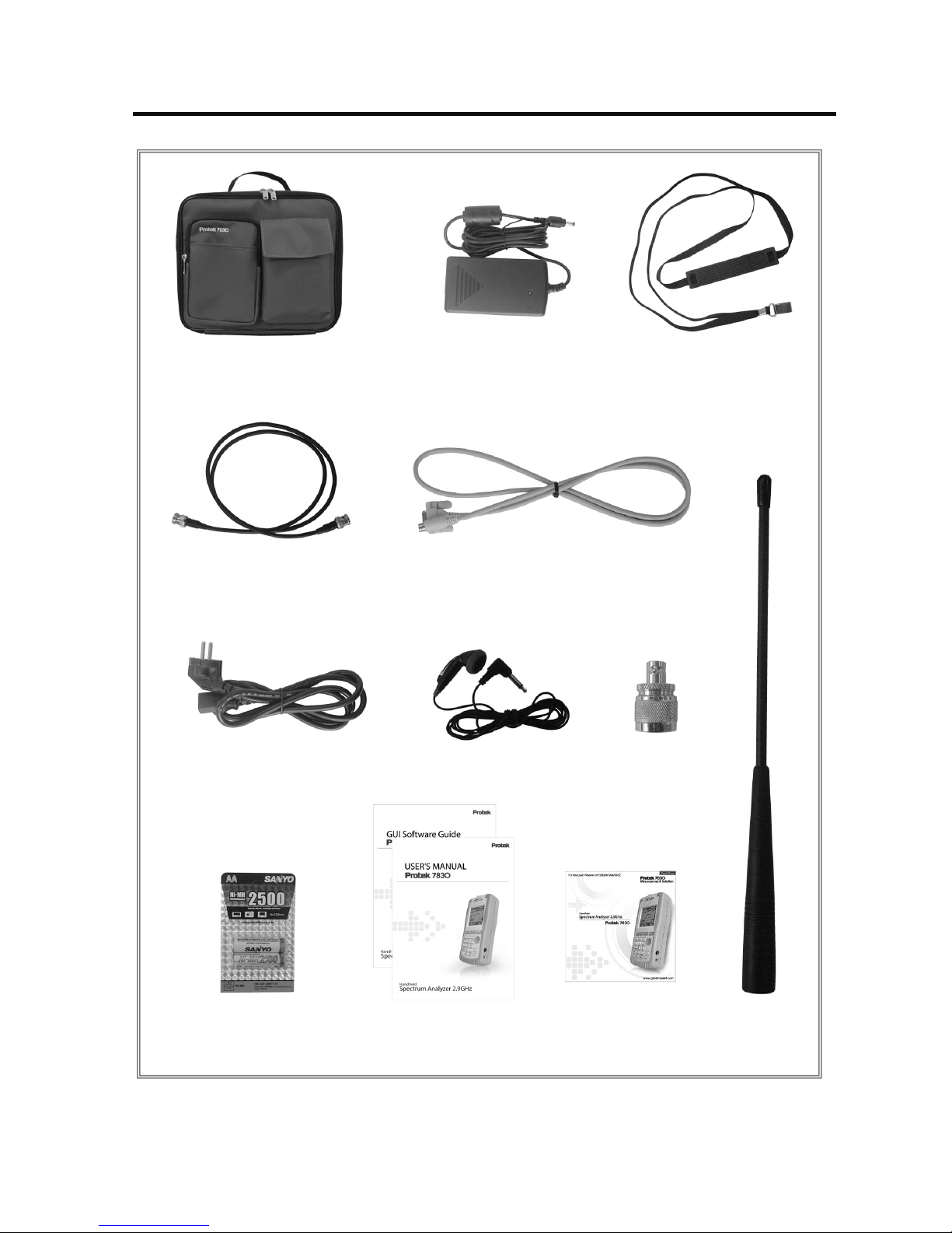
Accessories
※ Standard Option
Carrying case AC Adaptor
Carrying Strap
Coaxial Cable
RS-232 Cable
Power Cable
Earphones
N-BNC
Adaptor
Ni-MH (Rechargeable
Battery) 6PCS
User’s Manual
X 2PCS
Antenna
GUI Software CD
8
Page 10

9
1. Introduction
Overview……………………………….……………………………..……………….11
2. Features
Main Features …………………………………………………………………….…12
3. Functions
Spectrum Analyzer……………………………………………………………..…….13
Frequency Counter……………………………………………………….………….13
Specifications………………………………………………………………...……….14
4. Instrument overview
Front Panel………………………………………………………………………...….18
Rear Panel…………………………………………………………………………….20
Side Panel…………………………………………………………………………….21
Top Panel…………………………………………………………………………..….22
5. Basic operation
Before Power On…………………………………………………………….……….23
Power On……………………………………………………………………………...24
Turn on Power of Instrument………………………………..…………………….25
Description of operation screen…………………………..……………………….26
Reception Mode……………………………………………………………..……….32
Sweep Mode………………………………………………………………………….33
Set up Span……………………………………………………………………..…….34
Frequency Input……………………………………………………..………………. 35
Adjust Screen Level……………………………………………………….……….37
Run - Scanning…………………………………………………..….……………….38
Marker…………………………………………………………..…………………….39
Setting of attenuator………………………………………………………………….52
LCD Light……………………………………………………………………………...53
LCD Contrast………………………………………………………………………….54
Buzzer ON/OFF……………………………………………………..……………….55
Save/Load………………………………………………………….………………….56
Table of contents
Page 11

10
Frequency Counter…………………………………………………………….…….60
Power Source………………………………………………………………..……….62
Level Unit………………………………………………………………………..…….63
Reset………………………………………………………………………………..…64
Baud Rate…………………………………………………………………………..…65
Connection for PC……………………………………………………………………66
Auto Power……………………………………………………………………………67
Offset…………………………………………………………………………..………68
Menu……………………………………………………………..…………………….69
System……………………………………………………………..…….……………73
6. Description of key operating
Run [GHz] …………………………………………………………………….………76
Mode [MHz] ………………………………………………………………..…………76
Sweep [kHz] …………………………………………………………….……………77
Marker [DEL] …………………………………………………………………………77
No. 1 [Start/Stop] …………………………………………………….………………78
No. 2 [Span] ………………………………………………………………..…………78
No. 3 [Level] …………………………………………………………………….……79
No. 4 [PK Search; Peak Search] …………………………..………………………79
No. 5 [MKR to CNT; Marker to Center] ……………………………………………80
No. 6 [CH Power; Channel Power] ………………………..………………………80
No. 7 [LCD Light] ……………………………………………………….……………81
No. 8 [LCD CONT; LCD Contrast] …………………………………………………81
No. 9 [Attenuator] ……………………………………………………………………82
No. 0 [system] …………………………………………………………..……………82
Shift……………………………………………………………………………….……83
Dot [Buzzer] ……………………………………………………………..……………83
Menu [Load] ………………………………………………………………….………84
Enter [Save] …………………………………………………………….……………84
Up/Down Keys and Knob Key………………………………………………………85
7. G632 Manual…………………………………………………………………………86
Page 12

11
1
Overview
The Protek 7830 is a handheld spectrum analyzer and it is optimized to
analyze signals for the radio frequency equipment. The Protek 7830 has
adopted a synthesizer method and has a wideband reception range of
100 kHz to 2,900 MHz. The characteristics of frequency response of the
Protek 7830 is that the measuring data are corrected by memorized
calculation data, and so it enables Protek 7830 to measure accurate
levels and make it possible to analyze easily for a wide range of
frequency bands.
The Protek 7830 provides various functions and user-friendly interfaces
which make it easy for the users to check the location of the antenna with
simple handling. The Spectrum Analyzer is ideal for users to test, install
and maintain mobile telecommunications systems, cellular and cordless
phones, CB paging, paging systems, Cable and Satellite TV Systems as
well as antenna site measurements and maintenance. The Protek 7830
supports the RS 232C serial communication and has separate GUI
software. Users can control the Protek 7830 easily after connecting the
Protek 7830 with their personal computer, and can utilize the analyzed
data variously after converting or saving numerical values or graphs.
Introduction
11
Page 13

12
2
Main Features
100 kHz to 2,900 MHz measurement range
Frequency Spectrum Analyzing Function and Frequency
Counter Function
Measures and demodulates N-FM, W-FM, AM, SSB signals
Built-in Frequency Counter
Accurate Signal Level Measurement
Marker/delta Marker/Squelch Adjustment Function
Peak Search/Marker to Center Function
Channel Power Measurement Function
PLL tuning system for precise frequency tuning
Built-in Speaker
192 Pixels X 192 Pixels Back Light LCD
Menu selection method for Function selection
RS-232C Interface
User-friendly Icon Display
Maintenance of Wireless Telecommunications Equipments
General Usage for Installation and Maintenance of
telecommunications Equipments
Installation and Maintenance of Cable
RFID Tag RF Strength Measurement
Jammer (for hospital, theater and military) Performance Test
Installation and Maintenance of Satellite Antenna
Detection of Tapping and Hidden Camera
Features
Page 14

13
3
Spectrum Analyzer
Spectrum: Peak Search, Marker to Center, Channel Power
Function
Internal Attn.: The input range can be extended by internal
Max 35 dB Attn. function.
Sweep Mode: Single Run, Free Run, Squelch Run Selectable
Squelch Function: The Squelch Level may be adjusted to any
value from the reference level to Full Scale.
Copy Function: The Copy Set mode allows the contents of the
Channels edit Setup and Data memories to be copied to an
external device. Data may also be written into these memories
from external device
Frequency Counter
Frequency range: 35 MHz to 2,900 MHz
No. of digits: 7 digits
Resolution: 1 kHz
Functions
Page 15
14
Specifications
Frequency Range
100 kHz to 2,900 MHz
Resolution
Min. 6.25 kHz
Accuracy
TXO : ± 3 PPM / Display : ± 1.5 PPM
W-FM / N-FM
/ AM / SSB
Wide FM : Approx. 180 kHz @-6 dB
Narrow FM : Approx. 12.5 kHz @-6 dB
AM/SSB : Approx. 2.4 kHz @-6 dB
Step Range
AM, SSB, Narrow FM : 6.25kHz, 12.5kHz
Wide FM : 6.25~125kHz (Multiple of 6.25 kHz)
125~2500kHz (Multiple of 125 kHz)
Span Range
AM, SSB, Narrow FM : 1MHz, 2MHz
Wide FM : 1~20MHz (Multiple of 1 MHz)
20~400MHz (Multiple of 20 MHz)
Frequency
Selection Mode
Center, Start/ Stop, Span
Measurement
Range
-20 dBm to –110 dBm
Average noise
Level
Wide FM : -100 dBm Max.
Narrow FM : -110 dBm Max.
AM/SSB : -100 dBm Max.
Amplitude Units
dBm, dBmV, dBuV
Reference Level
Accuracy
Typical ±1.5 dB (@20~30℃/W-FM)
Typical ±1.5 dB (@25℃/N-FM/AM/SSB)
Reference Level
Range
-80 dBm to 0 dBm
Log Scale
0.2 dB/DIV min, in 0.25 dB Span (5 Display
Division)
Internal Attn
10 dB, 20 dB, 30 dB, 35 dB Max.
Internal Attn
Accuracy
±1.0 dB (@25 ℃)
Frequency
Amplitude
Page 16
15
Specifications
asdf
Typ e
Mono STN LCD
Display Resolution
192 Pixels X 192 Pixels
LCD Light
On / Off
Frequency Range
35 MHz to 2,900 MHz
Resolution
7 Digits
Accuracy
±50 PPM ±1 COUNT
Sampling Time
1 sec
Input Sensitivity
9 MHz to 2,000 MHz : 150 mVrms
20 MHz to 1,000 MHz : 100 mVrms
2,000 MHz to 2,900 MHz : 400 mVrms
Input Impedance
50 Ohms
Max. Input Voltage
5 Vrms Max.
Speed
Min. 500 msec
Trigger Source
Narrow FM / Wide FM / AM / SSB
Trigger Mode
Free Run / Single Run / Continuous Wave
/ Squelch Run
Trigger Level
TTL Level
Marker Mode
Maker / Delta Maker / Peak Search /
Marker to Center / Channel Power
Trace & Setup
Storage
Max 100 Waveforms and 100 States
Sweep
Memory
Display
Frequency
Counter
Page 17
16
Specifications
A
RF Input
Connector
N type Female, 50 Ohms
Max Input Level
Max. +10 dBm, 5Vrms
Operating
Temperature
0 ℃ to 40 ℃
Humidity
35 RH to 85 RH
P
Storage Temp.
10 ℃ to 50 ℃
Battery Power
Source
AA Type Ni-MH Rechargeable Battery × 6
PCS
Battery
Specification
AA Type 1.2 V, 2,700 mAh Rechargeable
Nickel Metal Hydride Battery
Adapter
SMPS Type AC Adapter (DC 12 V Output)
Car-Adapter (DC 12 V Output)
Auto Power On/Off
Off/ 5 min./ 10 min./ 20 min./30 min.
The Protek 7830 can be quickly recharged using a Ni-MH
rechargeable battery. For safe usage, it is strongly
recommended to use Ni-MH Rechargeable battery, and please
do not use in the place with high temperature or high humidity
during recharging.
Spectrum
input Port
Operation
Environment
Power
Source
Page 18
17
Specifications
Dimension
4.4 ”(W)×10 ”(H)×2.3 ”(D)
Weight
Approx. 0.70 Kg(1.54 lbm)
(including Antenna, except Battery)
Antenna (Receive Only), SMPS Type AC Adapter, Fuji-AA type NI-MH
Rechargeable Battery (6 PCS, 1.2 V 2,700 mAh), Manual, Coaxial
Cable, Earphones, Carrying Case, Carrying Belt, RS-232C Cable,
Adapter (N-BNC), Software for PC Application
Matching Pad (75 Ohms to 50 Ohms), F-BNC Adapter, Car Adapter,
Block Voltage Unit
Physical
Specifications
Standard
Accessories
Optional
Accessories
Page 19
18
4
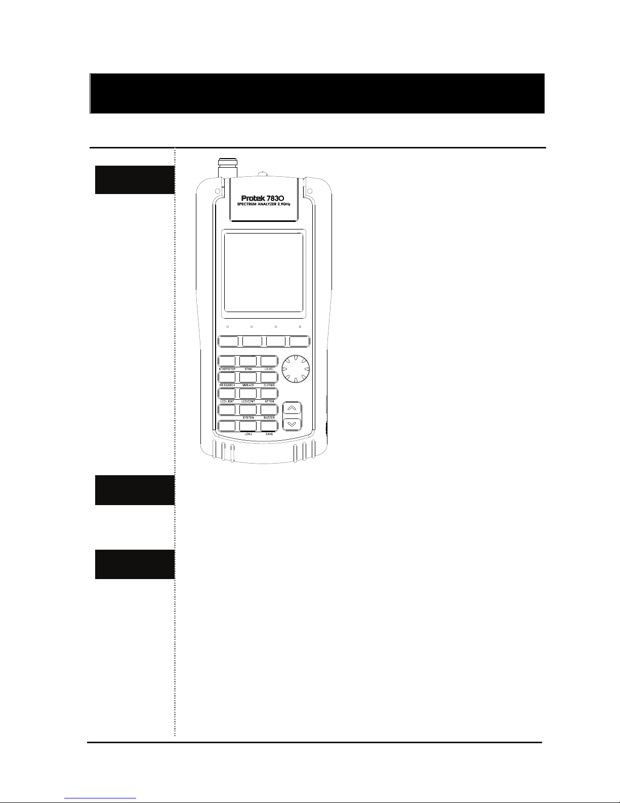
Front Panel
The LCD screen can display the signal input level, frequency and
amplitude values, and system data
Power Key
Key to turn ON/OFF of the system
Run / Mode / Sweep / Marker Key
Run
Key to run the Scanning or input the GHz unit for frequency value
input
Instrument overview
LCD
Front Figure
Key Pad
Shift
Power21Menu3Enter
456
789
0.
Run
GHz
Mode
MHz
Sweep
kHz
Marker
DEL
Page 20

19
Front Panel
Mode
Key to set up the Reception Mode or input the MHz unit for
frequency value input
Sweep
Key to set up the Sweep Mode or input the kHz unit for frequency
value input
Marker
Key to select the Marker Function:
Marker, Delta Marker, Squelch Marker, Peak Search, Marker to
Center, and Channel Power
Numeric Key
Key to input the frequency value
Menu Key
Key to set up the required functions of the system
Up/Down Key
Key to select the main menu items or frequency values
Knob Key
The function of Knob is same as the Up/Down keys
Page 21
20
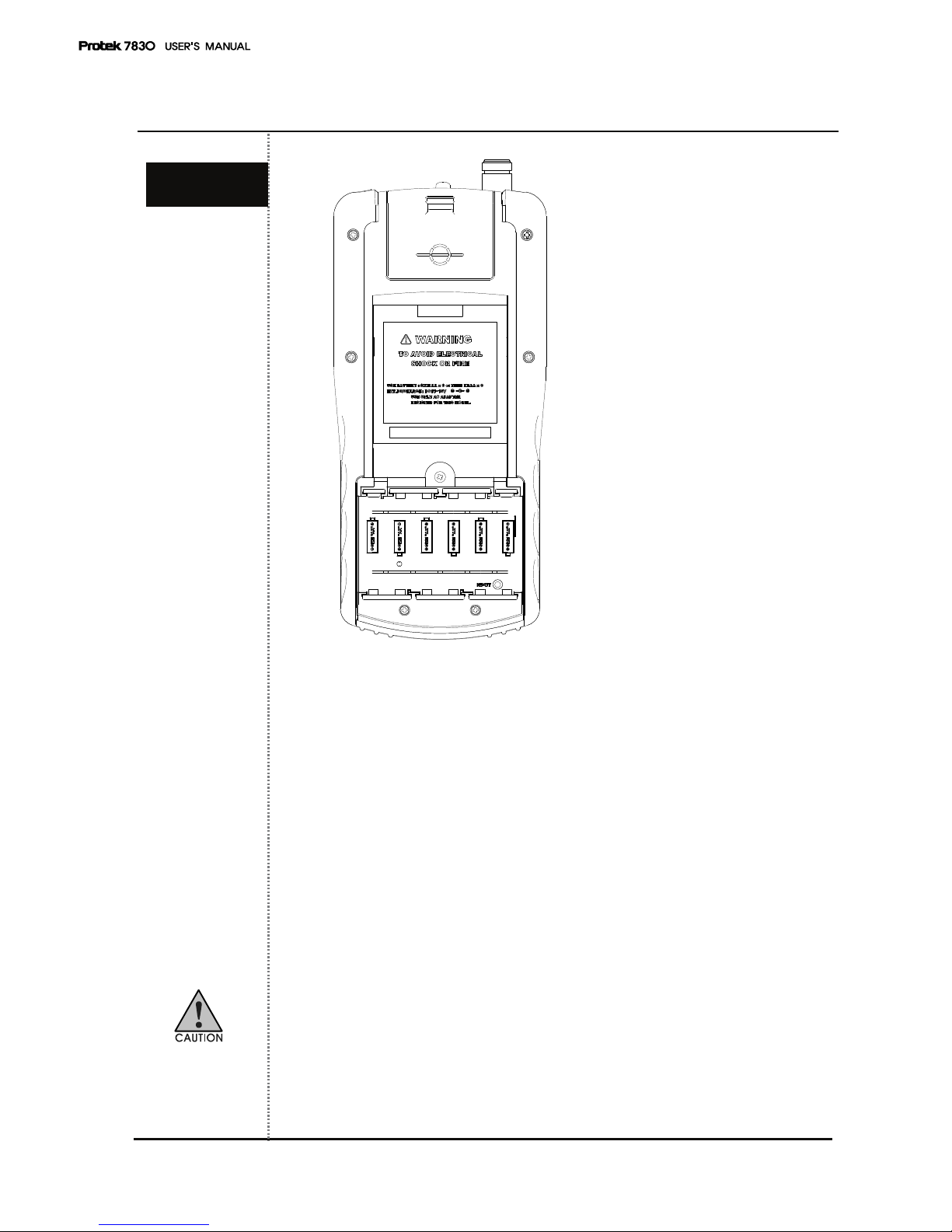
Rear Panel
Belt Clip
Users can yoke the Protek 7830 on a belt.
Speaker
Users can use the speaker to output the modulated audio from RF
signal level.
Reset Key
Users can use this Reset key from system’s malfunction or memory
reset.
Battery
Note the polarity of batteries at inserted battery compartment. And
users must use the AA type Ni-MH rechargeable batteries for battery
charging
Rear Figure
Page 22
21
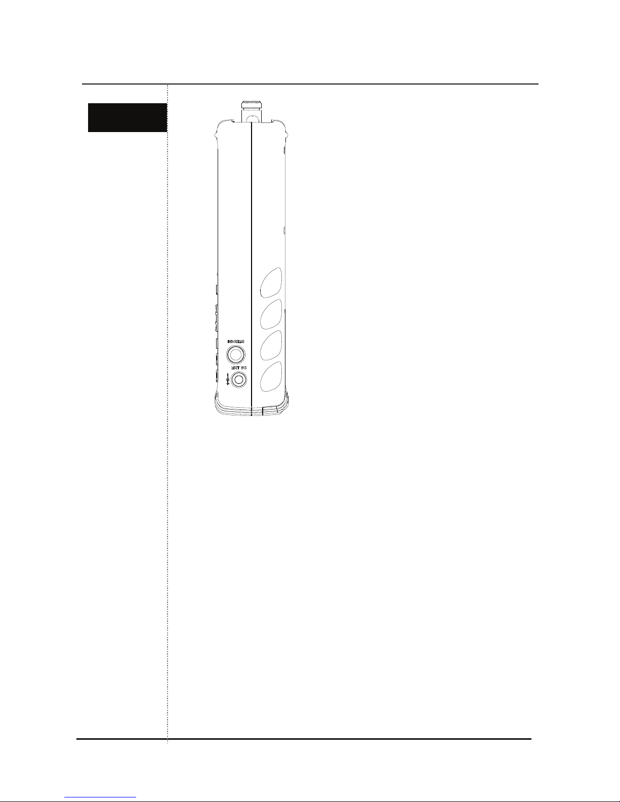
Side Panel
DC Input Jack
Users can use this DC input jack for power supply and battery
charging with SMPS type AC/DC Adapter or Car Adapter.
RS-232C Connector (8 pin mini DIN connector)
Users can use the RS-232C connector for PC communications with
a serial cable.
Side Figure
Page 23
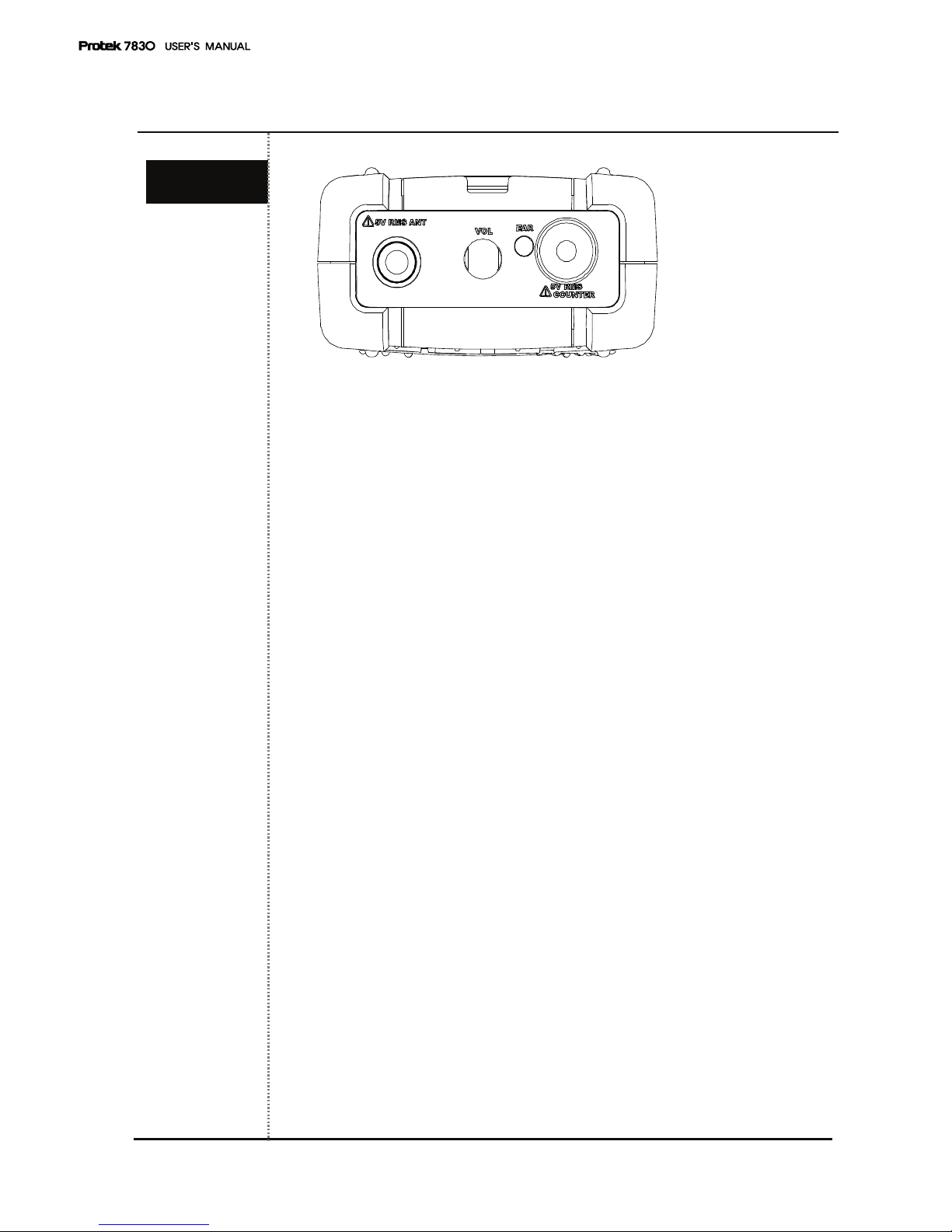
22
Top Pa n e l
Input Connector for Signal Level
Users can connect the antenna or coaxial cable to this connector on
the system. The maximum input voltage is 5 Vrms.
Input Connector for Frequency Counter
Users can connect the signal source to this connector as an input.
The maximum input voltage is 5 Vrms.
Volume Control
Users can control the volume of audio outputs. To increase the
volume of audio output, turn the volume control to the clockwise
direction.
Earphones Jack
Top Figure
Page 24
23
5
Before Power ON
For the insertion of batteries, please release the screw on the battery
cover on the bottom of the instrument. And put AA Type Ni-MH
rechargeable batteries (Total 6 PCS) in.
To charge the batteries after inserting batteries, connect the DC cable
plug of SMPS type adaptor to DC jack of the system (DC output: 12V).
Battery charging will begin after DC cable is connected.
At this time, if users turn on the power of the system, the battery icon
on the display window is displayed and blinking. And if the charging of
batteries is finished, the blanking of battery icon will stop and only be
displayed.
To measure the input level of RF signal, connect the antenna or
coaxial cable to the N-type connector of the system (marked ANT)
Input Connector for RF Signal Level:
Users can connect the antenna or coaxial cable to this connector
on the system. The maximum input voltage is 5 Vrms
Input Connector for Frequency Counter:
Users can connect the signal source to this connector as an input.
The maximum input voltage is 5 Vrms.
Basic Operations
Connection
for Input
Level
Page 25
24
Power ON
To turn on the system power, Press the key.
When the system power is ON, the last displayed screen from the
previous usage will be displayed (Previous setup status).
This system supports shortcuts with the combination of keys. To use
this shortcut function, press the key and press the numerical key.
The frequently used function description is marked on the numerical key
below. The upper right icons are the basic
mode and the
mode. Users can select the shift mode or basic
mode by pressing
the key.
For the LCD display, refer to below figure.
Page 26
25
Turn on power of instrument
STEP 1
- Push the Key.
STEP 2 (Adjust to LCD Contrast)
- Push the Key.
- Push the LCD CONTRAST (No.8)
Key.
- Adjust to desired LCD Contrast using the Up/Down
Keys
or Knob
Key.
STEP 3
- Push the Dot Key to be taken out of Menu.
STEP 4 (LCD Light On/Off)
- Push the Shift Key
STEP 5
- Push the No. 7 (LCD Light) Key
Power On
Page 27
26
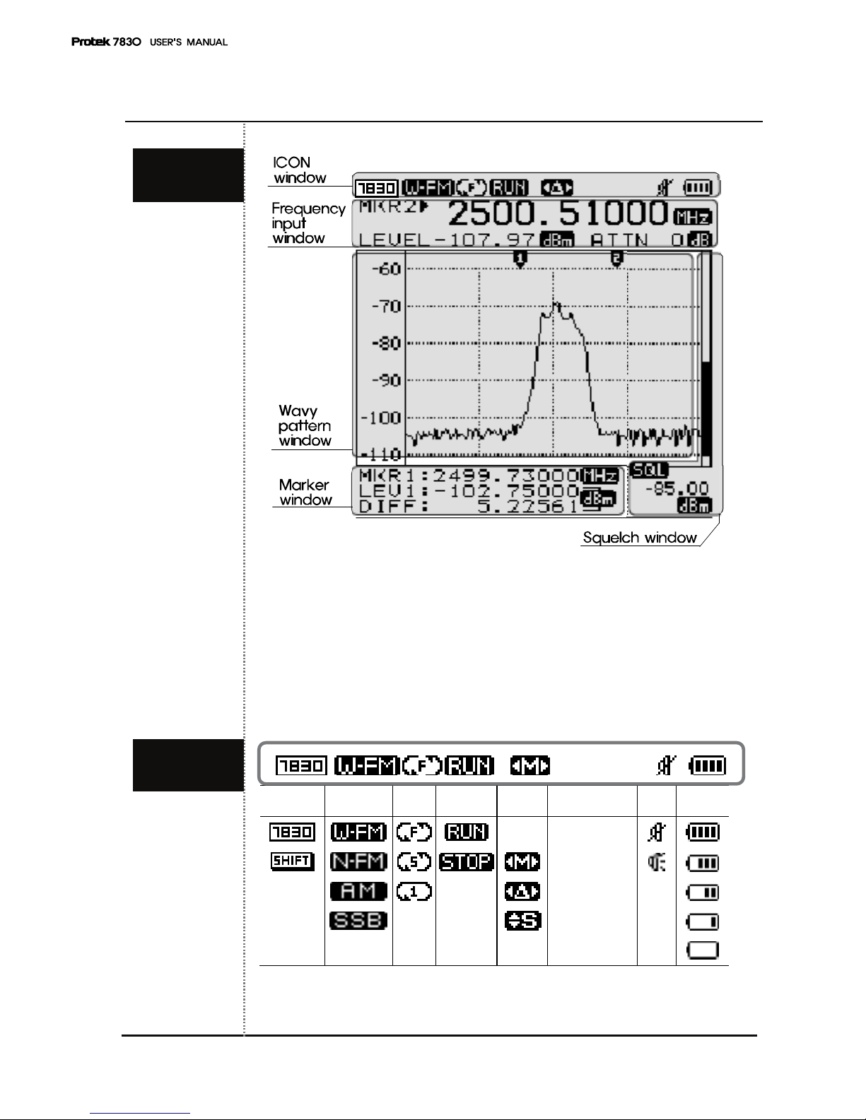
Description of operating screen
1. ICON window 2. Frequency Input window
3. Wavy pattern window 4. Squelch window
5. Marker window
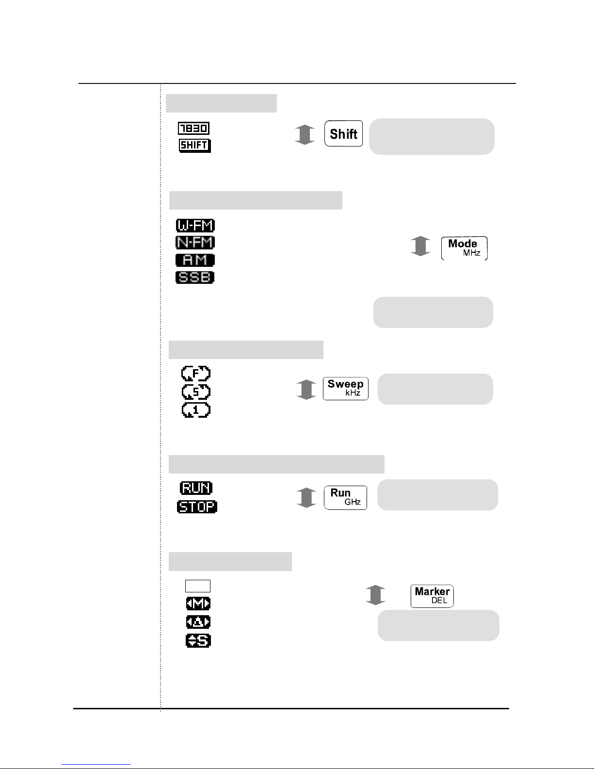
ⓐ ⓑ ⓒ ⓓ ⓔ ⓕ ⓖ
1. ICON
window
Page 28
27
Description of operating screen
ⓐ Shift State Indication
Normal state
Shift Input state
ⓑ Reception Mode State Indication
Wide Frequency Demodulation Mode
Narrow Frequency Demodulation Mode
Amplitude Modulation Mode
Single side band Demodulation Mode
ⓒ Sweep Mode State Indication
Free Run
Squelch Run
Single Run
ⓓ Run-Scanning Run/Stop State Indication
Running
Stop
ⓔ Marker State Indication
None Center Marker State
Marker 1 State
Delta Marker State Marker 1, 2
Squelch Marker State
Pushing the shift key
changes the icon.
Pushing the mode key
changes the icon.
Pushing the sweep
key changes the icon.
Pushing the run key
changes the icon.
Pushing the marker
key changes the icon
Page 29

28
Description of operating screen
ⓕ Buzzer On/off Indication
Buzzer Off
Buzzer On
ⓖ Battery Residual Indication
Full
Empty
ⓐ
주파수 값 표시
ⓔ
LEVEL
ⓑ
ⓒ
ATTN
ⓓ
2. Frequency
Input
window
Icons are changed by
Dot(Buzzer) key
Page 30

29
Description of operating screen
ⓐ Center Frequency Indication NONE
Maker 1 Frequency Indication
Maker 2 Frequency Indication
Frequency Counter Value Indication
CHPW Channel Power Value Indication
-
Indication of Frequency Value of each Mode
ⓑ Level Value Indication
Indication of Level Value of each Mode.
ⓒ Level Unit
Can be selectable in the main menu.
[Please refer to Menu Level Unit establishment for further details]
ⓓ Atten. Establish Value
Indicate established Attenuation Value.
[Please refer to Menu Level Unit establishment for further details]
ⓔ Frequency Unit
Every Frequency Unit is indicated in MHz
Page 31

30
Description of operating screen
ⓐ
Indication Reference
Value of Screen
Level Value
Indication to Vertical Level Value of
Wavy pattern window.
[Please refer to screen level
establishment in basic operations
for further details]
ⓑ
Resolution of Screen
Level Value
ⓒ
Marker Indication
Center
Marker
Every Marker can be controlled by
the Up/Down
keys or
Knob
Key.
Marker 1
Marker 2
3. Wavy
pattern
window
ⓐ
ⓑ
ⓒ
Page 32

31
Description of operating screen
Center Marker, Marker 1, When Squelch Marker ⓐ
CENT
Center Frequency
MHz
SPAN
Span Frequency
STEP
Step Frequency
When Delta Markerⓑ
MKR1
Marker 1 Frequency MHz
LEV1
Marker 2 Level Value
dBm
DIFF
Marker1- Marker2 Level Value
When Measuring Channel Power ⓒ
CENT
Center Frequency
MHz
SPAN
Span Frequency
CHBW
Channel Bandwidth
MHz
4. Marker
Window
Page 33

32
Reception Mode
Reception Mode has total (4) four modes for demodulation when
receiving.
Wide-FM
Wide Frequency Modulation
Wide FM RBW (Resolution Bandwidth) 180 kHz
Narrow-FM
Narrow Frequency Modulation
Narrow RBW (Resolution Bandwidth) 12.5 kHz
AM
Amplitude Modulation
SSB /AM RBW (Resolution Bandwidth) 2.4 kHz
SSB
Single Side Band Modulation
SSB /AM RBW (Resolution Bandwidth) 2.4 kHz
The Wide FM mode is ordinary used to interpret a large signal of
bandwidth; the Narrow FM mode is used to interpret a narrow Bandwidth
Signal. AM and SSB can be used irrespective of Bandwidth.
Push Mode (MHz)
Key to establish the reception mode and then
the top-left ICON will be changed to WFM , NFM , AM
, SSB in order. When inputting frequency like Start/Stop,
Span etc, The Mode (MHz)
Key is used.
RBW is fixed in each Mode as follows.
Wide FM RBW (Resolution Bandwidth) 180 kHz
Narrow RBW (Resolution Bandwidth) 12.5 kHz
SSB/AM RBW (Resolution Bandwidth) 2.4 kHz
STEP 1
- Push the Mode (MHz) Key.
STEP 2
- Push the Mode (MHz) Key and the top left ICON will change to
WFM
, NFM , AM and SSB order.
Reception
Mode
Establishment
Page 34

33
Sweep Mode
The Sweep mode is used to interpret the characteristics of input signals.
Every each characteristics of the sweep mode is as follow.
Establish this mode by pushing the Sweep (kHz)
Key and then the
top left ICON will be changed to FREE Run , SQUELCH Run
and SINGLE Run in order. The Sweep (kHz) Key is used as
input Start/Stop, Span and Input Frequency Unit into kHz Unit.
After frequency is inputted, FREE Run continues to execute Run-
Scanning operation automatically.
Squelch Run operation will stop Run-Scanning in case of the signal
level value is getting higher than the squelch level value. But, If the signal
level is getting lower than the squelch level, restart to Run- Scanning.
After input is finished Start/Stop Frequency,
Single Run execute
Run-Scanning just a once. In addition, if it is desired to Run-Scanning,
push the Run (GHz)
Key and then execute Run-Scanning once
STEP 1
- Push the Sweep (kHz) Key
STEP 2
- Push the Sweep (kHz) Key, and the top-left ICON will be
changed to
FREE Run, SQUELCH Run and SINGLE
Run order.
Free Run
Analyzing execution consecutively
Single Run
Only 1 time Execution
Squelch Run
Run by higher than Squelch level
(Similar Trigger Mode of Oscilloscope)
Sweep
Mode
Establishment
Page 35

34
Set up Span
Setting of step for Span means Frequency Resolution and Span can be
adjusted from 1MHz to 400MHz. And the step at Narrow FM, SSB and AM
can be set 1MHz to 2MHz. Wide FM from 1MHz to 20MHz is 1MHz step
and step at 20MHz to 400MHz can be set at 20MHz step.
If the correct value is not set, value will be set at a lager value
automatically.
Example) If Span Input is 50 MHz, it would automatically be set at 60
MHz.
First, push the Shift Key in order to set up Span. Then the top-left
ICON is changed
to .
After that, push the No. 2 Key. So then Frequency Input window changes
the Span Input State.
Enter the span size and then input the appropriate unit such as Run
(GHz)
, Mode (MHz) or Sweep (kHz) Key.
STEP 1
- Push the Shift Key
STEP 2
- Push the No. 2 Key
- When the Sweep (kHz) Key is pressed, the top-left ICON is
changed to FREE Run, SQUELCH Run and
SINGLE Run in order.
Set up
Span Mode
Page 36

35
Frequency Input
Chosen Reception Mode, Sweep Mode and Span are showed on the top
center of LCD. At first, choose Reception Mode and Sweep Mode to get a
sense of the Frequency Bandwidth and a specific feel for analyzing.
Choosing Frequency Value is a way to inputting Center and Start/Stop
Frequency. In order to input Center Frequency, just pushes the numeral
keys. Press the key when Frequency Input Window is a CENT state.
Push the Shift Key to input Start/Stop Frequency. Then, push the
No. 1(Start/Stop)
Key, to input Start Frequency in Frequency Input
Window. Input Frequency by using the No. 0
to 9 Keys, Dot
(Buzzer)
Key, MARKER (DEL) Key and Run (GHz)
as Unit Input Key, Mode (MHz)
and SWEEP (kHz) Key.
Execution will be done automatically, after inputting the last Unit in the
Frequency, according to a given Sweep Mode of Run-Scanning Mode. If
the mode is Single Run
, push the Run (GHz) Key and then
execute Run-Scanning again.
A wrong inputting content can be erased by using the MARKER (DEL)
Key. The MARKER (DEL) Key operates like the backspace
on a PC
Erase inputted Frequency and then push the Marker (DEL) Key once
more; you are now out of Frequency Input Mode.
Page 37

36
Frequency Input
STEP 1
- Check the state of Frequency Input Window.
You can input Center Frequency when state of Frequency Input Window
is CENT
.
STEP 2
- Input a desired Center Frequency
STEP 3
- Input a unit by using the Run , Mode and Sweep Key
STEP 1
- Push the Shift Key
STEP 2
- Push the No. 1 Key
STEP 3
- Make sure that Frequency Input Window is changed to Start Input
Mode. Input a desired Frequency to use the numeral keys and the Dot
Key
STEP 4
- Input a unit to use the Run , Mode and Sweep Key
STEP 5
- Make sure that Frequency Input Window is changed to Stop Input Mode.
Input a desired Frequency using the numeral keys and Dot
Key.
STEP 6
Input a unit to use the Run , Mode and Sweep Key.
Start/Stop
Frequency
Input
Page 38

37
Adjust screen Level
To Settle Top Level- Reference Level and Level Resolution on screen.
“RLEV” is an abbreviation of Reference Level.
Choose through the Up/Down
Keys and establish the level
using the Enter
Key. Top Level in the vertical axis would be changed
to be established Value.
“DIFF” is an abbreviation of Difference.
Choose through the Up/Down
Keys and establish to use the
Enter
Key. Level Step in verticality axis would be changed to
established Value
RLEV
Choose through the Up/Down Keys and push
the Enter Key.
DIFF
Choose through the Up/Down
Keys and push
the Enter Key.
RLEV
DIFF
Page 39

38
Run-Scanning
Run-Scanning is a process interpreting Frequency according to
established Frequency Bandwidth and Span. And Run- scanning
processes operates by established Sweep Modes
Page 40

39
Marker
Protek 7830 has Center Marker, Marker 1, Delta Marker (Marker1 and
Marker2) and Squelch Marker. Each Marker Mode is displayed on the top-
left as a Marker Mode ICON.
Marker Mode
ICON
Marker ICON Remarks
Center Marker
No ICON
Center Marker
Marker 1
Users can move Marker 1 to the
desired position.
Marker 2
Users can move Marker1 or
Marker 2 to the desired position.
Users can see the difference of 2
markers.
Squelch Marker
When making FM/AM/SSB signals
to be audible, this marker is
working as a volume of the sound
and this marker is used to set a
standard for the Squelch Run.
Page 41

40
Marker
Center Marker is not a Mode the users can select when using Mark
Mode in the basic operations. When inputting Start Frequency and Stop
Frequency, Center Frequency, the information will appear automatically.
Frequency and Level on Center Frequency will be indicated on
Frequency Input Window.
Center
Marker
Page 42

41
Marker
To use Marker 1 , press the Marker (DEL) key in
Center Marker status. When it turns to Marker 1 mode, Marker mode icon
is changed to . And frequency input window is changed to Center
Marker to Marker 1
.
To move the Marker 1, use the Up/Down keys, or the Knob
key. Then the frequency value and level value are displayed on
frequency input window
STEP 1
- Press the Marker (DEL) Key.
- Check the Marker 1
mode in display window
STEP 2
- To move the Marker 1 to wanted plot point, please use the Up/Down
keys, or Knob key.
- Then the frequency value and level value are displayed in the frequency
input window
Marker 1
Page 43

42
Marker
Press the Marker (DEL)
Key until the Marker mode icon is
changed to Delta Marker in the display window. And in this case,
Marker 2 is added.
The Marker mode is the total four modes. And the changing order of
Marker mode is as below:
Center Marker 1 Delta Maker Squelch Marker
When users set up the Delta Marker, the frequency value and level value
of Marker 2 are displayed in the frequency input window. The frequency
value and level value of Marker 1, and the difference level value between
Marker 1 and Marker 2 are displayed in the Marker window
Delta Marker
To handle the Marker 1, users can set up the marker 1 in Marker mode 1
To handle the Marker 2, users can set up the marker 2 in Delta Marker
Page 44

43
Marker
STEP 1
- Press the Marker (DEL) Key.
- Check the Delta Marker
mode in the display window
STEP 2
- To move the Marker 1 to the desired plot point, please use the Up/Down
keys, or Knob key.
- Then, the frequency value and level value of Marker 2 are displayed in
the frequency input window.
The frequency value and level value of Marker 1, and the difference
level value between Marker 1 and Marker 2 are displayed in the Marker
window. Then the frequency value and level value are displayed in the
frequency input window
Page 45

44
Marker
To know the magnitude of frequency, users can use the Squelch Marker.
Also, users can set up the Squelch Marker for setting the Squelch Level
of Sweep mode and speaker output for a larger signal than Squelch Level
through modulation for audio frequency ranges. (Modulation: Frequency
modulation, Amplitude modulation, and SSB Modulation)
Press the Marker (DEL) Key until the Marker mode icon is
changed to the Squelch Marker in the display window.
Squelch
Marker
Page 46

45
Marker
STEP 1
- Press the Marker key.
- Check the Squelch Marker mode.
STEP 2
- Move the Squelch Marker to the desired point using the Up/Down
Keys or Knob Key.
- The squelch value is displayed in the lower right display window.
Page 47

46
Marker
Peak Search
To use the Peak Search function, this function must be run in Marker 1
mode.
Press the Marker (DEL)
Key until the Marker 1 icon and
Marker 1 are displayed in the display window.
The Marker mode is the total four modes and the changing order of
Marker mode is as below:
Center Marker 1 Delta Maker Squelch Marker.
Move the Marker 1 to the desired point using the Up/Down
Keys or Knob
Key.
Press the Shift key to change the
icon to the .
And press the No. 4 (PK Search)
key.
Functions
using
Marker
Page 48

47
Marker
STEP 1
- Press the Marker (DEL) Key.
- Check the Marker 1 mode in the display window.
STEP 2
- Press the Shift key
STEP 3
- Press the No. 4 (PK Search) key.
Then, the Marker 1 is moved to the peak point, and the frequency value
and level value are displayed in the frequency input window
The function for Peak Search must be run in only Marker 1
mode
Page 49

48
Marker
Peak/Marker to Center
To use the function of moving Marker 1 to the center or Marker 1 to the
peak value of the display window, this function must be run in Marker 1
mode.
Press the Shift key to change the upper right icon to
. And press the No. 5 (Marker to CNT) Key.
Then, the Marker 1 position will be in the center of the display window
(Center frequency).
Also, to find the peak value, press the Shift key and push No. 4 (Peak
Search). Then, the marker will be located in the point of a highest signal.
Page 50

49
Marker
STEP 1
- Press the Marker (DEL) Key.
- Check the Marker 1
mode in the display window.
STEP 2
- Move the Marker 1 to the desired point using the Up/Down
Keys or Knob Key
STEP 3
- Run the function for Peak Search by pushing Shift + No.4
- Make sure that the marker is located on the peak signal.
STEP 4
- Press the Shift key
STEP 5
- Press the No. 5 (Marker to CNT) key
The function for Peak/Marker to Center must be run only in
Marker 1
mode
Page 51

50
Marker
Channel Power Measurement
To run the function for channel power measurement, users can get into
this mode by pushing Shift + No. 6 (CH Power) or selecting Channel
Power item in the main menu. The above display shows the illustration of
the channel power measurements.
The default channel power bandwidth is the half of the span size. In this
mode, the span size can be adjustable by pushing Shift + No. 2(SPAN).
In this mode, the Marker to Center frequency function is disabled and if
the Peak search function or Marker key is selected, the channel power
mode comes to an end and the system is working based on the input
mode.
Page 52

51
Marker
STEP 1
- Press the Shift + No. 6 (CH Power) Or
- Select CH. POWER item on Marker in the main menu.
STEP 2
- Input the center frequency.
STEP 3
- Move the Marker to select the desired channel power ranges using the
Up/Down
Keys or Knob Key
STEP 4
-To be out of this mode
Press the Shift + No. 6 (CH Power) Or
Select CH. POWER item on Marker in the main menu.
Page 53

52
Setting of Attenuator
The internal attenuator is used for maximum input signal -20dBm with
Menu function.
To set the internal attenuator, press the Shift key to change the
upper right icon
to .
And press the No. 9 (ATTN)
key.
To adjust the value of internal attenuator, press the Up/Down
Keys or rotate the Knob
key. And Press the Enter key.
Setting for
Internal or
External
Attenuator
Page 54

53
LCD Light
The LCD Light is designed to ease the use of the instrument in a dark
location.
Press the Shift key to change the upper right icon
to .
And press the No. 7 (LCD Light)
key.
*The Power ON/OFF of the LCD Light will toggle
STEP 1
- Press the Shift key
STEP 2
- Press the No. 7 (LCD Light) key
If the LCD light is ON, the battery will drain faster than usual.
Page 55

54
LCD Contrast
The function of LCD contrast is to adjust the contrast for the remaining
battery capacity.
Press the Shift key to change the upper right icon
to
.
And press the No. 8 (LCD Contrast)
key.
The LCD contrast is adjusted by using the Up/Down
keys or
Knob
key. And press the Enter key.
STEP 1
- Press the Shift key
STEP 2
- Press the No. 8 (LCD Contrast) key
STEP 3
- To adjust the LCD contrast, use the Up/Down keys or Knob
key and press the Enter key
Page 56

55
Buzzer ON/OFF
User can set the Buzzer ON/OFF (Toggle ON/OFF)
Press the Shift Key. Then the Icon
of left upper window is
changed to shift icon .
And press the Dot Key.
STEP 1
- Press the Shift key
STEP 2
- Press the Dot Key
Page 57

56
Save/Load
The function of Save/Load is for the Waveform and Setup Status.
The function of Save is for concurrently saving the Waveform and Setup
Status in memory.
And the saved Setup Status in memory includes the following information:
Reception mode, Sweep mode, Frequency range, Step value, and Span
value. User can use this with Menu or Multi key.
The function of Load is for loading the saved Waveform and Setup Status
in memory.
If user only wants the Setup Status, please load the saved file for desired
Setup Status. And press the Run key. Then this measuring instrument will
complete the Run-scanning operation. User can only use this in Menu.
The function of Delete is for deleting the saved file. Also, users can only
use this in the Menu.
Save
Page 58

57
Save/Load
STEP 1
- Press the Shift key
STEP 2
- Press the Enter key
STEP 3
- To save the waveform or setup status, a name with at least 7 characters
is required.
- To select each character, use the Up/Down
keys. And press
the Enter
key
- If want to save the file name fewer than 10 characters, press the “END’
on stated inputted file name.
STEP 4
- To delete the character, press the Marker key
STEP 5
- When all 7 characters included blank are typed, press the Enter
key. Then, output message for SAVE OK is displayed.
“SAVE OK”
- If user does not type the all 7 characters included blank, the function of
save is not completed
STEP 6
- To cancel the Save, press the Marker key until the first character
is deleted. And additionally press the Marker
key one time.
- Then the Save is canceled and the output message is displayed as
below.
“SAVE FAILED”
- The values to be saved are signal and system setting values. Buzzer,
LCD contrast and LCD light states are not saved.
Page 59

58
Save/Load
STEP 1
- Press the Shift key
STEP 2
- Press the Menu key
STEP 3
- To load the waveform or setup status, select a filename to retrieve.
- To select the first character. Use the Up/Down
keys. And
press the Enter
key
The function of Load is to load the saved waveform and setup status.
If user only wants to load only setup status, load the user’s saved data
and press the Run
key.
Then system will run in loading setup status. (Run-scanning)
Load
Page 60

59
Save/Load
STEP 1
- Press the Menu key
STEP 2
- To select the DELETE, use the Up/Down keys or Knob
key and press the Enter
key
STEP 3
- To delete the saved data, select the user’s saved data using the
Up/Down
keys or Knob key. And press the Enter
key. Then the saved data will be deleted
STEP 4
- Confirm to prevent users from losing data mistakenly
Delete
Page 61

60
Frequency Counter
Select the F.counter under Main Menu – function
The input connector for the frequency counter is BNC connector.
When the input level is inputted into the Frequency Counter, the
measured frequency value is displayed in the frequency input window
Input level is as below.
9 MHz to 2,000 MHz : 150m Vrms
20 MHz to 1,000 MHz : 100m Vrms
2,000 MHz to 2,900 MHz : 400m Vrms
Page 62

61
Frequency Counter
STEP 1
- Press the Menu key
STEP 2
- To select the FUCTION, use the Up/Down keys or Knob
key and press the Enter
key.
- Then sub menu is opened.
STEP 3
- To select the F. COUNTER (Frequency Counter), use the Up/Down
keys or Knob key and press the Enter key
STEP 4
- The icon is displayed from the other icon.
The FCNT is displayed in the frequency input window
STEP 5
- When the input level is inputted in the Frequency Counter using BNC
connector, the measured frequency value is displayed in the frequency
input window
STEP 6
- To change the Frequency Counter mode to Spectrum mode, run the
upper Step 1 to Step 3. At this time, select the SPECTRUM not F.
COUNTER in
Step 3
Page 63

62
Power Source
To check the battery’s remained capacity Battery, users can refer to the
battery icon on the upper area of the display window
How to use and replace the battery
[Please refer to the batter section in details.]
Checking
for Battery
Page 64

63
Level Unit
The setting for level unit can be set up in the Menu.
The level unit can be set up as below
□ dBm
□ dBuV
□ dBmV
STEP 1
- Press the Menu key
STEP 2
- To select the LEVEL UNIT, use the Up/Down keys or Knob
key and press the Enter key.
Then sub menu is opened.
STEP 3
- To select the user’s wanted level unit, use the Up/Down keys
or Knob
key and press the Enter key
Setting of
the Unit
Page 65

64
Reset
The function of Reset is for initializing the memory or system. The three
kinds of resets are supported. And these resets are run through the Menu
Preset
System Reboot for initial setup status.
(Center Frequency, Span Frequency, Marker and etc)
Memory CLR
The user’s saved data will be cleared. (Memory Cleared)
System INIT
The upper two resets (PRESET and MEMORY CLR) are run.
Then, system reboot for initial setup status and the user’s saved data will
be cleared
STEP 1
- Press the Menu key
STEP 2
- To select the RESET, use the Up/Down keys or Knob
key and press the Enter
key.
- Then, sub menu is opened.
STEP 3
- To run one of Reset modes, use the Up/Down keys or Knob
key and press the Enter key.
- Then, the selected reset will be run.
STEP 4
- Confirm the selection again to prevent users from losing their data
mistakenly.
Page 66

65
Baud Rate
The setting of the baud rate is for the transmission speed.
The Baud Rate between PC and 7830 system is as below.
STEP 1
- Press the Menu key
STEP 2
- To select the BAUD RATE, use the Up/Down keys or Knob
key and press the Enter key.
Then, sub menu is opened.
STEP 3
- To select the baud rate value users want, use the Up/Down
keys or Knob key and press the Enter key
115,200 BPS
57,600 BPS
38,400 BPS
19,200 BPS
9,600 BPS
4,800 BPS
Setting of
the Baud
Rate
Page 67

66
Connection for PC
To connect 7830 to a PC, carefully follow the procedures as below.
1. Make sure the serial cable is connected from a PC to 7830.
2. Choose “CONNECT PC” on the main menu.
3. Run 7830 GUI Program on the PC.
STEP 1
- Press the Menu key
STEP 2
- To select the CONNECT PC, use the Up/Down keys or Knob
key and press the Enter key.
Then, sub menu is opened.
STEP 3
- To select the REMOTE PC, use the Up/Down keys or Knob
key and press the Enter key.
Then, run the GUI Program included in the package..
Setting of
the
Connection
for PC
Page 68

67
Auto Power Saving
The Auto Power saving function is used to conserve system power.
When “NONE” is not selected, the power source will be turned off
automatically based on the time users select.
The auto power OFF time is same as below
NONE
05MINUTES
10MINUTES
20MINUTES
30MINUTES
STEP 1
- Press the Menu key twice
STEP 2
- To select the AUTO POWER, use the Up/Down keys or Knob
key and press the Enter key.
Then, sub menu is opened.
STEP 3
- To select the auto power time, use the Up/Down keys or
Knob key and press the Enter key
Page 69

68
Offset
Level Offset compensates for any loss due to the cabling.
Offset adds the value of +Offset to all the values of measurement.
STEP 1
- Press the Menu key twice.
STEP 2
- Set the cursor on Offset using the Up/Down Keys or knob
Key.
STEP 3
- Push the Enter Key and then move to the submenu.
- Input the dB value of Offset.
- Push the Enter Key
STEP 4
- Push the Menu Key once more to exit the system menu.
Page 70

69
Menu
Functions in the main menu can be selected using the combination keys
or through the Menu.
The functions that can be selected in the main menu mode are as below.
To exit from Menu or System, push the Menu Key or push the Dot
key. These keys will move users to the menu items either lower or higher.
In the tree structured menu.
Level Unit
Reset
Band Rate
Connect PC
Page 71

70
Menu
STEP 1
- Press the Menu key
STEP 2
- To select functions users want, use the Up/Down Keys or the
Knob
Key.
STEP 3
- Push the Enter Key
STEP 4
- After selecting function of sub items or On/Off, push the Enter
Key
STEP 5
- Exit the Menu after pushing the Menu Key twice.
- When the Menu
Key is pushed one time, it leads users to System
Menu.
Page 72

71
Menu
Function
Spectrum
Set up the functions of
Spectrum and frequency
counter.
Frequency Counter
TEST Mode
Reception
Mode
N-FM
Set up the Reception
Mode.
W-FM
SSB
AM
Sweep
Mode
Free Run
Set up the Sweep Mode.
The mode can be set up
with the Shift Key.
Squelch Run
Single Run
Marker
None
Marker or function using
the Marker.
The mode can be set up
with the Shift Key.
Marker
Delta MKR
Squelch MKR
PK Search
MKR 2 CENT
CHAN POWER
Save
Save Data
The mode can be set up
with the Shift Key.
Load
Load Data
The mode can be set up
with the Shift Key.
Level Unit
DBm
DbuV
DBmV
Page 73

72
Menu
Reset
Pre Reset
Restarting the System and
clear all the parameters for set
up
Memory CLR
Delete the stored data
System INI
All Reset – restarting the
system and delete the stored
data
Band Rate
115,200 BPS
Select the speed of serial
communication between the
unit and PC
57,600 BPS
38,400 BPS
19,200 BPS
9,600 BPS
4,800 BPS
Connect
PC
None
Select the connection to PC
Remote PC
Page 74

73
System
There are modes that select the function using the Shift Key and
the other keys. Also, the functions can be selected from main Menu and
System Menu..
To exit from Menu or System, push the
Key or push the Dot key,
this will move users up to higher menu items in the tree structured menu.
The functions that can be selected in the System Menu are as below.
Page 75

74
System
Get into System Menu
STEP 1
- Press the Menu Key
- Or Shift + No. 0
key is a shortcut for the System Menu (Go
to Step3)
STEP 2
- Press the Menu Key once more.
STEP 3
- To select desired function, use the Up/Down Keys or the
Knob Key
STEP 4
- Press the Enter Key
STEP 5
- After selecting a lower item function or On/Off, push the Enter Key
STEP 6
- Push the Menu Key once to exit the System
Page 76

75
System
Auto Power
None
Select auto power saving
mode.
05 Minutes
10 Minutes
20 Minutes
30 Minutes
Buzzer
ON
Select Buzzer On/Off.
OFF
LCD Light
ON
Select LCD Light On/Off.
OFF
LCD Contrast 1 to 10 Step
INT. Atten.
0 dB
10 dB
20 dB
30 dB
35 dB
Offset -99.0 dB to 99.0 dB
Default save SAVE
During booting,
save default values to be
applied.
When saving the values, all
values will be saved except
signals.
Page 77

76
6
Run [GHz]
Instruction to start scanning frequencies
After power on, this button will work as it did under the most
recent setup, or when Squelch Run
or Single Run
function is activated.
[Please refer to the Scan section for basic operations in details if
needed]
Selecting a unit (GHz) to input Start/ Stop/ Scan/ Center
frequencies.
After inputting the frequency values, push this key to add
a unit of GHz..
Mode [MHz]
Selecting Reception Mode
The following Reception Modes can be selected WFM ,
NFM ,AM and SSB .
[Please refer to the Reception Mode section for detailed basic
operations.]
Selecting a unit (MHz) to input Start/ Stop/ Scan/ Center
frequencies.
After inputting the value of frequencies, push this key to add a unit of
MHz.
Description of key operations
Page 78

77
Sweep [kHz]
Selecting Sweep Mode
This button selects the Sweep Mode such as FREE Run ,
SQUELCH Run
and SINGLE Run
[Please refer to the Sweep Mode section for detailed basic operations.]
Selecting a unit (kHz) to input Start/ Stop/ Scan/ Center
frequencies.
After inputting the value of frequencies push this key to add a unit of
kHz.
Marker [DEL]
Selecting Marker functions.
After pushing this button, please select Marker functions such as Center
Marker, Marker 1, Delta Marker and Squelch Marker.
[Please refer to the Marker section for basic operations in details.]
This is a delete function when setting up Start/Stop/Scan/Center
frequencies.
When inputting the frequency values, the Marker Key can be
used as the Delete Key working as a backspace key on a PC.
Page 79

78
No. 1 [Start/Stop]
Press the No. 1 key to input the value of 1.
To input the value of numeral 1 in the Start/Stop/Scan/Center
frequencies, please use the No. 1
Key.
Pressing the Shift Key and No.1 key will activate the
Input function for Start/Stop Mode.
Select the Start/Stop Mode by pushing the Shift Key and than
push the numeral
Key.
[Please refer to the Frequency Input section for basic operations.].
No. 2 [Span]
Push the No. 2 key to input the value of 2.
To input the value of numeral 2 in the Start/Stop/Scan/Center Mode,
push the No. 2
Key.
Span Frequency Input function can be activated by pushing
Shift Key
By pushing the Shift Key and than pushing the No. 2 Key,
the Span Mode is activated.
[Please refer to the Span section for detailed basic operations.]
Page 80

79
No. 3 [Level]
Push the No. 3 key to input the value of 3.
In order to input the value of numeral 3 in the Start/Stop/Scan/Center
frequencies, push the No. 3
Key.
Display Level Adjustment Function by pushing Shift
Key.
On pushing the Shift Key and then push the No. 3 Key,
users can adjust the basic level of vertical axis and level steps on the
display.
[Please refer to the Display Level Adjustment section for detailed
basic operations if need.]
No. 4 [PK Search; Peak Search]
Push the No. 4 key to input the value of 4
Use the No. 4 Key to input the value of numeral 4 in the Star/
Stoop/ Scan/ Center frequencies.
Marker Search and Peak Search can be activated by
selecting the Marker after pushing the Shift Key.
Peak Search Function, one of the marker functions, is selected by
pushing the Shift Key and then pushing the No. 4 Key.
[Please refer to the Peak Search section for detailed basic operations if
needed.]
Page 81

80
No. 5 [MKR to CNT; Marker to Center]
Push the No. 5 key to input the value of 5.
Push the No. 5 Key to input the value of numeral 5 in the Start/
Stop /Scan/ Center frequencies.
Activate the Marker to Center Function using the Marker menu after
pushing the Shift Key.
On pushing the Shift Key and then push the No. 5 Key,
Marker to Center, one of the marker functions, can be selected.
[Please refer to the Marker to Center section for detailed descriptions
for using the Marker Function if needed.]
No. 6 [CH Power; Channel Power]
Push the No. 6 key to input the value of 6.
The No. 6 Key is used to input the value of numeral 6 in the
Start/Stop/Scan/Center frequencies.
Selecting Channel Power Function using the Marker function after
pushing the Shift Key
By pushing the Shift key and then pushing the No. 6 Key,
Channel Power, one of marker functions, is selected.
[Please refer to the Channel Power section for detailed basic
operations if needed]
Page 82

81
No. 7 [LCD Light]
Push the No. 7 key to input the value of 7.
When inputting the value of numeral 7 in the Start/Stop/Scan/Center
frequencies, the No. 7
Key is used
LCD Light Function after pushing the Shift Key
By pushing the Shift key and then pushing the No. 7 Key,
LCD Light is turned on or off.
[Please refer to the LCD Light section for details about basic operations
if needed.]
No. 8 [LCD CONT; LCD Contrast]
Push the No. 8 key to input the value of 8.
To input the value of numeral 8 in the Start/Stop/Scan/Center
frequencies, the No. 8
Key is used.
LCD Contrast Function after pushing the Shift Key
By pushing the Shift key and then pushing the No. 8 Key,
users can adjust the LCD Contrast level.
[Please refer to the LCD Contrast section for details on basic
operations.]
Page 83

82
No. 9 [Attenuator]
Push the No. 9 key to input the value of 9.
To input the value of numeral 9 in the Start/Stop/Scan/Center
frequencies, the No. 9
Key is used
Attenuator Setup Function after pushing the Shift Key
By pushing the Shift key and then pushing the No. 9 Key,
users can select the level of an internal attenuator.
[Please refer to the Attenuator Setup section for details about basic
operations.]
No. 0 [System]
Push the No. 0 key to input the value of 0.
When inputting the value of numeral 0 in the Start/Stop/Scan/Center
frequencies, the No. 0
Key is used.
System Setup Function after pushing the Shift Key
By pushing the Shift key and the No. 0 Key, System Setup
function is selected.
[Please refer to the System Setup section for details about basic
operations.]
Page 84

83
Shift
Using the Function Key
The Shift Key does not perform any functions by itself.
The Shift Key is used to perform functions printed below the numeral
keys.
If the shift key is pressed twice, CENT/SPAN located on the bottom of
display is changed to START/STOP.
Dot [Buzzer]
The Dot key is used to input a decimal point
When inputting the value of Decimal Point in the Start/Stop/Scan/Center
frequencies, this key is used.
Buzzer Setup Function after pushing the Shift Key
By pushing the Shift key and then pushing the Dot Key,
Buzzer On or OFF is selected.
[Please refer to the Buzzer section for details on basic operation.]
Return Function on Menu and System
Return Function is used to return from lower Menu to higher Menu on
Main Menu and System Manu.
Page 85

84
Menu [Load]
Menu Function
Various functions can be selected after entering Menu..
At the Menu, pushing the Menu Key again; it will activate the
System Menu.
[Refer the section of Menu and System of basic operation if need more
detail]
Load Function after pushing the Shift Key.
By pushing the Shift key and the Menu Key, stored data
are loaded after selecting a file on the list
[Please refer to the Store Mode section for details of basic operation.]
Enter [Save]
Enter Function
The Enter Key is used to select Menu or System items.
Save/Load Function after pushing Shift Key
By pushing the Shift key and Enter Key, data are saved
after typing a file name.
[Please refer to the Save/Load section for details about basic
operations.]
Page 86

85
Up/Down Keys and Knob Key
Up/Down Keys and Knob Key Functions
Up/Down keys and knob are used for the movement of markers and
menu / system items
Page 87

86
Page 88

87
1. Protek G632
1. PROTEK G632
Protek G632 has been developed as a CW Signal Generator, which generates signal
at -55 to - 65dBm within 30MHz to 2.9GHz bandwidth. G632 is connected to
Protek7830 via RS-232
2. Features
Protek G632 is a tracking generator for handheld Spectrum Analyzer 7830.G632
supports signal generating function & analyzing function
3. Specification
Item Specifications
Frequency Range 30MHz ~ 2.9GHz
Amplitude
Measurement Range (-)55dBm ~ (-)65dBm / 5dB steps
Amplitude Units DBm
Level Accuracy
±2.0dB (Typical-95%) (@20℃~30℃)
±3.0dB (Other-5%) (@20℃~30℃)
Power Power Source
SMPS Type AC Adapter DC 12V
((Using RS-232, Power supply is provided by
7830)
Dimension
& Weight
Size (W X H X D) 60 X 135 X 40mm
Weight Approximately 200g
Interface Interface RS-232
General
Specification
Operation Temperature
0℃ ~ 40℃, Spec
Secured Temperature: (@20℃~30℃)
Humidity 0% ~ 80% RH
RF Output Connector N Type Connector
Page 89

88
4. Operation
PROTEK 7830 – MENU – MENU - GEN OUTPUT – “LEVEL SELECTION” (-55/-60/-65dBm)
(Operation) (Signal Generation)
5. G632~7830 Level Setting Procedure
1) Connect cable between G632 and 7830
2) Signal generated from G632 at -60dBm
3) Check 7830 Level
4) Level difference between -60dBm and 7830 can be compensated from
“offset” menu in 7830
※ 7830 offset setting procedure
;7830, MENU – MENU – OFFSET – (+)/(-) selection – input offset value in dB - ENTER
User’s Manual
Page 90

89
6. Application: 900MHz Band Pass Filter Test
<Test Conditions>
A. Tracking Generator Output Signal Level: -60dBm
B. Measuring Device: 900MHz Band Pass Filter
C. Test Block Diagram
<Test Results>
A. 7830 Output Signal Level: -61.70dBm
B. Path Loss(G632~7830): 1.5dB
1) Band Pass Filter: 1.4dB 2) Cable Loss: 0.1dB
C. 7830 LCD Display (Center Freq.: 900MHz, SPAN: 100MHz, Mode: Wide FM)
(Before connecting Filter) (After connecting Filter)
RS 232
Cable
BPF
Page 91

90
7. Cautions when linking G632 to 7830
A. Fix Int. Atten.: Fix INT. Atten of 7830 to 20 dB when connecting with G632.
B. Ext. Atten.
- Ext.Atten of 7830 disabled when connecting with G632.
C. 7830 Mode Change: Changing Mode disabled when connecting with G632.
User’s Manual
 Loading...