

Page 1
VOLTEX 50 RV PLUS
User Manual
Cellular Signal Booster
RV
Page 2
This publication provides instructions for installing Signal Booster VOLTEX 50 RV PLUS.
Copyright© 2018, American Booster Inc.
All Rights Reserved.
Revision History
Date Version Changes
2018, October Version 1.0 Original
2018, December Version 1.1 Original
Certication
This equipment complies with the FCC directives.
Technical Support : 913 469 6699 www.americanbst.com
Page 3

INDEX
Product Introduction
Package Contents
Installation Guide
Step 1. Mount Outside Antenna
Step 2. Connect Cable to Outside Antenna
Step 3. Booster Installation
Step 4. Connect Inside Antenna to the Booster
Step 5. Power up the Booster
Booster Performance
LED Indicators
Troubleshooting
Antenna Kit Option
4
5
6
6
7
8
9
10
11
12
13
14
Specications
Safety Guidelines
FCC Warning Statements
IC Warning Statements
Warranty
15
16
17
18
19
Page 4
VOLTEX 50 RV PLUS
50dB
GAIN
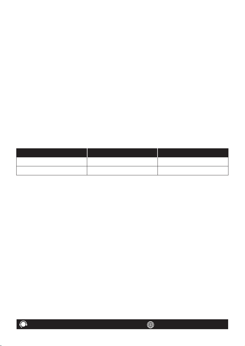
The American Booster® VOLTEX 50 RV PLUS has been designed to provide
an advanced solution for boosting your signal and fastening your data
speeds anytime, anywhere.
How it works
Receives Signal
The signal booster’s outside
antenna receives voice and
data signals from a nearby
cell tower.
4
Boosts Signal
The signal booster receives
the signal from the outside
antenna and after amplifying
the voice and data signals, sends
them to the indoor antenna.
VOLTEX 50 RV PLUS
Improves Signal
The indoor antenna
distributes the boosted
signals throughout
your vehicle.
Page 5
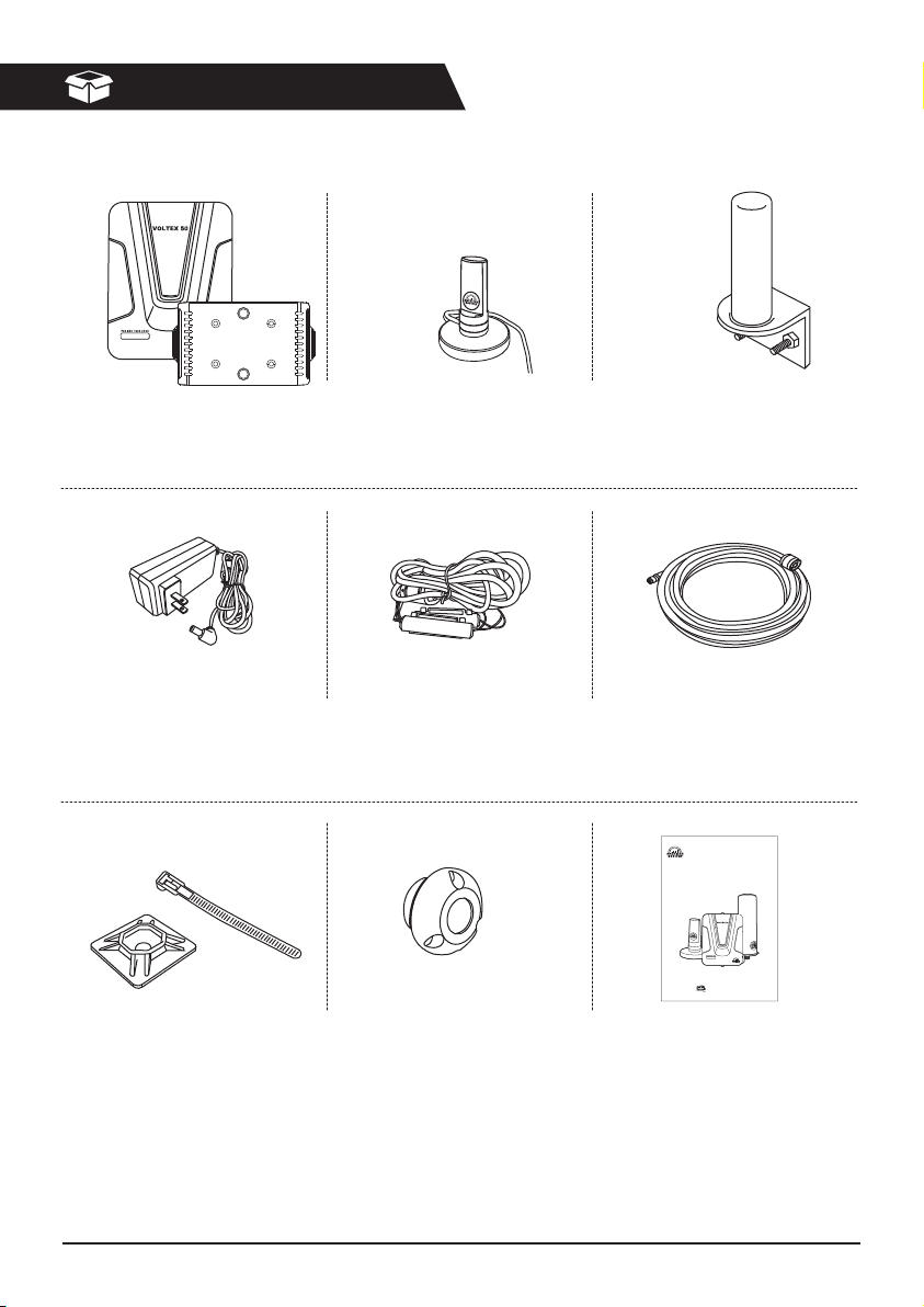
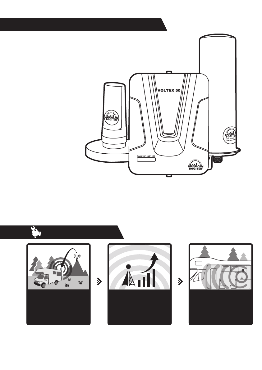
Package Contents
Signal Booster VOLTEX 50
Code No. : 835T7
AC/DC Adapter
Code No. : 835U3
Cable Mounts
& Ties (×15ea)
Inside Antenna Kit
Code No. : 835TF
Hardwire Power Cable
Code No. : 836HW
Cable Entry Cover
Outside Antenna Kit
Code No. : 835TG
Coaxial Cable 20ft.
Code No. : 8368J
VOLTEX 50 RV PLUS
User Manual
Cellular Signal Booster
RV
User Manual
VOLTEX 50 RV PLUS
5
Page 6
Installation Guide
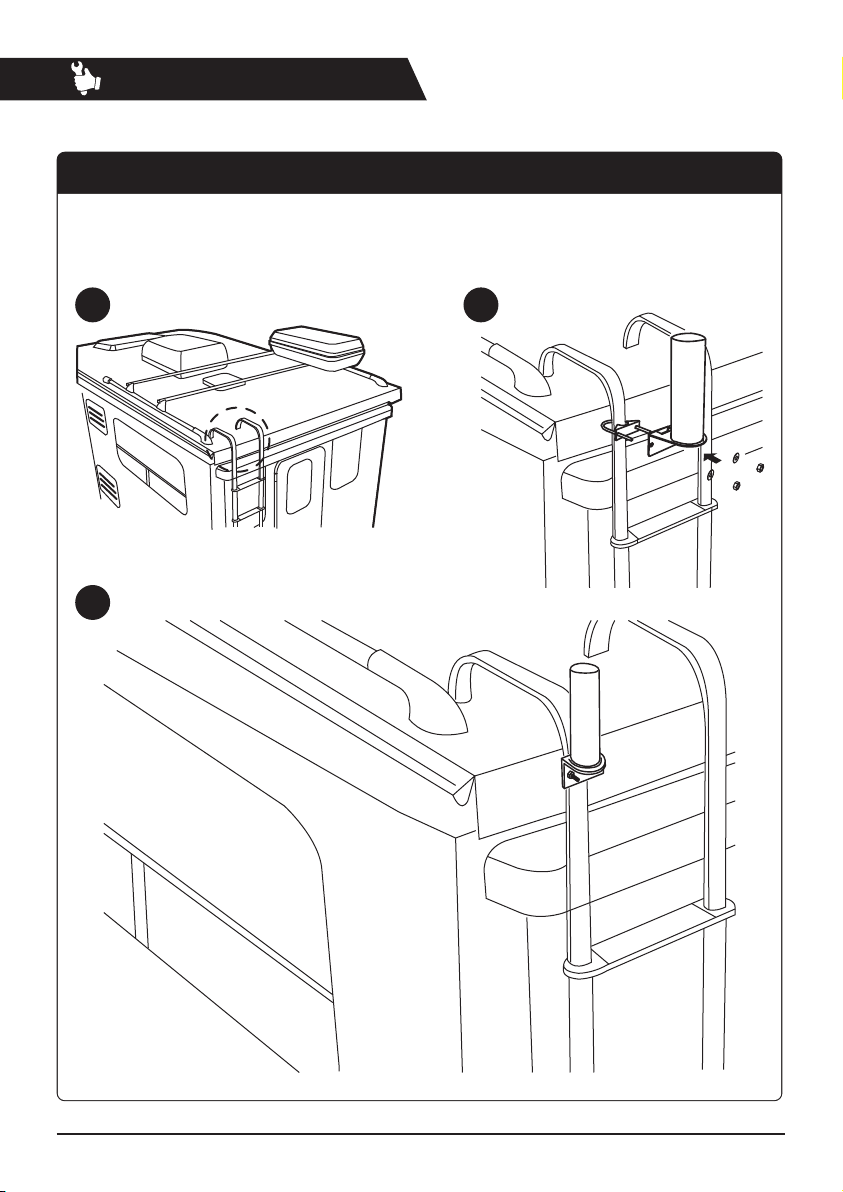
Step 1. Mount Outside Antenna
Choose where you want to have the outside antenna on your RV and make sure the
antenna is in a location within the reach of the booster with a 20 ft. coaxial cable.
We would recommend mounting the outside antenna on the pole or ladder of your RV.
1 2
3
6
VOLTEX 50 RV PLUS
Page 7

Step 2. Connect Cable to Outside Antenna
Assuming you don't have any holes, drill a 1 inch hole on your RV for the coaxial cable to
pass through the RV and connect the outside antenna to the booster.
1
1 inch bit hole
WARNING
Check if there are no wires, pipes or cables that
can be damaged during the drilling a hole.
3
Cable Entry Cover
2
4
VOLTEX 50 RV PLUS
Cable Mounts
7
Page 8

Step 3. Booster Installation
1
Find a place to install the booster.
32
From outside antenna
Mount the bracket.
Snap the booster into the bracket.
8
From inside antenna
Connect the cables.
VOLTEX 50 RV PLUS
Page 9

Step 4. Connect Inside Antenna to the Booster
Place the inside antenna close to your phone or tablet for an optimal performance.
1
2
VOLTEX 50 RV PLUS
9
Page 10

Step 5. Power up the Booster
Connect the AC/DC power adapter to the booster and plug into a power source.
The power LED will light, indicating that the signal booster is ready for use.
10
We provide hardwire DC power cable option as well.Note
VOLTEX 50 RV PLUS
Page 11

Booster Performance
The Booster's performance depends on the signal strength you are receiving through outside antenna.
-70dB
Outside Antenna1
2
VOLTEX 50
Inside Antenna3
Inside Antenna3
VOLTEX 50 RV PLUS
-90dB
2
VOLTEX 50
Outside Antenna1
11
Page 12

LED
LED Indicators
Flashing Green
After the Signal Booster is powered on, ashing green will last for 20 seconds.
It means that the Signal Booster is being set up for an optimal performance.
The Signal Booster will need a few minutes to adapt to the network environment and start boosting
the signal at the highest power.
The Signal Booster provides real-time self-diagnosis, so in case of ashing or solid red, refer to the
Troubleshooting instructions below.
Solid Green
This indicates that the Signal Booster has been installed and works properly.
Solid Orange
It means that the input signal from the nearby cell tower is between -25dBm and
-30dBm, so you are recommended to change RV position for receiving weaker signal.
Flashing & Solid Red
This indicates that the input signal from the nearby cell tower is too strong.
After ashing red for 10 seconds the solid red will appear.
Signal Booster will stop amplifying signals of the frequency with a solid red indicator automatically
to prevent the Booster from any damage.
If the rest of LEDs are green and you have a strong signal and fast data speeds on your cell phone or
tablet, then troubleshooting is not needed.
12
VOLTEX 50 RV PLUS
Page 13

Troubleshooting
Instructions to x ashing or solid red.
If you have a good voice signal and fast data speeds even though one or two of LEDs are solid red,
you may continue to use the Signal Booster as it is.
But if one of LEDs has ashing or solid red, your voice signal is weak and data speeds are low, then
troubleshooting of the Booster is necessary.
1. Unplug the Signal Booster’s power adapter.
2. Check if the Outside Antenna and Inside Antenna are located far enough from each other.
3. Plug the Signal Booster into a power source.
4. Check the LED on the Signal Booster. If ashing or solid red appears, repeat steps 1 through 3 and
relocate Inside and Outside Antennas.
5. If you have any diculties with installation or troubleshooting the Signal Booster, please contact
our technical support team for assistance (913-469-6699).
Light O
1. If there is no light on the Signal Booster, verify if it is connected to a power source correctly.
Try to unplug and plug back the power adapter.
2. Check if there is any damage in the power cable.
3. Check if there is any damage in the Signal Booster’s connector.
VOLTEX 50 RV PLUS
13
Page 14

Antenna Kit Option
Inside Antenna Option
Desktop Antenna with 17ft. RG58_SMA (Male) cable_835TF
Patch Antenna with 10ft. RG174_SMA (Male) cable_835LH
Panel Antenna with N Connector_83616(Use RG174 35ft. 50Ω N(Male) to SMA(Male)
Coaxial Cable_837NM)
Dome Antenna with N Connector_83617(Use RG174 35ft. 50Ω N(Male) to SMA(Male)
Coaxial Cable_837NM)
Outside Antenna Option
Magnetic Antenna with 13ft. RG174_SMA (Male) cable_835LL
Omni Antenna with N Connector_835TG (Use 5D-FB 20ft. 50Ω N (Male) to SMA (Male)
Coaxial Cable_ 8368J)
Marine Antenna with 13ft. RG58_SMA (Male) cable_836C9
Truck Antenna with 13ft. RG58_SMA (Male) cable_837C4
14
VOLTEX 50 RV PLUS
Page 15

Specications
Parameter
700MHz LTE
800MHz Cellular
1900MHz PCS
2100MHz AWS
Composite Power
Maximum Gain
Noise Figure
Impedance
RF Connector
Power Connector
Power
Size, inch
Weight, lbs
Operation Temperature
Humidity
-
For a detected oscillation, the device output will turn o within 300 ms for the Uplink and 1 second
Downlink Uplink Remark
734MHz ~ 757MHz
2110MHz ~ 2155MHz
5dBm 23dBm
5dB nominal
SMA Female
DC 12V / 3A
5.12 × 6.5 × 1.0
23 ~ +122°F (-5 ~ +50°C)
704MHz ~ 716MHz
776MHz ~ 787MHz
824MHz ~ 849MHz869MHz ~ 894MHz
1850MHz ~ 1915MHz1930MHz ~ 1995MHz
1710MHz ~ 1755MHz
50dB
50 Ohm
DC-045B
1.21
0 ~ 80%
Band 17 & 13
Band 17
Band 5
Band 25
Band 4
W × H × D
for the Downlink and remained o for 1 minute.
And, the device will have a maximum of 5 attempts at restart from oscillation before permanently
shutting o. Noise power, gain, and linearity are maintained by the device’s microprocessor.
VOLTEX 50 RV PLUS
15
Page 16

Safety Guidelines
WARNING
ELECTRIC SHOCK
Opening the Signal Booster could result in electric shock and may cause severe injury.
DAMAGE TO EQUIPMENT
Use only the power supply provided in this package.
Operating the Signal Booster with antennas in very close proximity facing each other could lead to
a severe damage to the Signal Booster.
CAUTION
THE SIGNAL BOOSTER SHOULD BE INSTALLED AS CLOSE AS POSSIBLE TO THE POWER SOURCE.
THIS REPEATER IS FOR INDOOR USE ONLY AND SHOULD BE INSTALLED INSIDE OF THE VEHICLE.
FCC ID : U88-VOLTEX50 IC : 8137A- VOLTEX50
This is a CONSUMER device
This device complies with Part 15 of the FCC Rules. Operation is subject to the following two
conditions: (1) this device may not cause harmful interference, and (2) this device must accept
any interference received, including interference that may cause undesired operation.
BEFORE USE, you MUST REGISTER THIS DEVICE with your wireless provider and have
your provider’s consent. Most wireless providers consent to the use of signal boosters.
Some providers may not consent to the use of this device on their network. If you are unsure,
contact your provider. In Canada, BEFORE USE you must meet all requirements set out in ISED
CPC-2-1-05. You MUST operate this device with approved antennas and cables as specied
by the manufacturer. Antennas MUST be installed at least 20 cm (8 inches) from (i.e.. MUST NOT
be installed within 20 cm of) any person.You MUST cease operating this device immediately if
requested by the FCC (or ISDE in Canada) or a licensed wireless service provider.
WARNING. E911 location information may not be provided or may be inaccurate for calls
served by using this device.
MODEL : VOLTEX50
For more information on registering your signal booster with your wireless provider, please see below
https://www.sprint.com/en/legal/signal-boosters.html?id16=signal%20booster
https://support.t-mobile.com/docs/DOC-9827
https://www.verizonwireless.com/solutions-and-services/accessories/register-signal-booster/
https://securec45.securewebsession.com/attsignalbooster.com/
https://www.uscellular.com/uscellular/support/fcc-booster-registration.jsp
16
VOLTEX 50 RV PLUS
Page 17

FCC Warning Statements
FCC Part 15.105 statement Class B
This equipment has been tested and found to comply with the limits for a Class B digital device, pursuant to part
15 of the FCC Rules. These limits are designed to provide reasonable protection against harmful interference in a
residential installation. This equipment generates, uses and can radiate radio frequency energy and, if not installed
and used in accordance with the instructions, may cause harmful interference to radio communications. However,
there is no guarantee that interference will not occur in a particular installation. If this equipment does cause harmful
interference to radio or television reception, which can be determined by turning the equipment o and on, the user is
encouraged to try to correct the interference by one or more of the following measures:
- Reorient or relocate the receiving antenna.
- Increase the separation between the equipment and receiver.
- Connect the equipment into an outlet on a circuit dierent from that to which the receiver is connected.
- Consult the dealer or an experienced radio/TV technician for help.
FCC Part 15.21 statement
Any changes or modications not expressly approved by the party responsible for compliance could void the user's
authority to operate this equipment.
RF Exposure Statement
The antenna(s) must be installed such that a minimum separation distance of at least 20cm is maintained between
the radiator (antenna) and all persons at all times. This device must not be co-located or operating in conjunction
with any other antenna or transmitter.
Use of unauthorized antennas, cables, and/or coupling devices not conforming with ERP/EIRP and/or indoor‐only
restrictions is prohibited.
VOLTEX 50 RV PLUS
17
Page 18

IC Warning Statements
RSS-GEN, Sec. 7.1.2 – (transmitters)
Under Industry Canada regulations, this radio transmitter may only operate using an antenna of a type and maximum
(or lesser) gain approved for the transmitter by Industry Canada. To reduce potential radio interference to other users,
the antenna type and its gain should be so chosen that the equivalent isotropically radiated power (e.i.r.p.) is not more
than that necessary for successful communication.
Conformément à la réglementation d’Industrie Canada, le présent émetteur radio peut fonctionneravec une antenne
d’un type et d’un gain maximal (ou inférieur) approuvé pour l’émetteur par Industrie Canada.
Dans le but de réduire les risques de brouillage radioélectrique à l’intention desautres utilisateurs, il faut choisir le type
d’antenne et son gain de sorte que la puissance isotroperayonnée quivalente (p.i.r.e.) ne dépassepas l’intensité
nécessaire à l’établissement d’une communication satisfaisante.
RSS-GEN, Sec. 7.1.2 – (detachable antennas)
This radio transmitter (identify the device by certication number, or model number if Category II)has been approved
by Industry Canada to operate with the antenna types listed below with the maximum permissible gain and required
antenna impedance for each antenna type indicated. Antenna types not included in this list, having a gain greater than
the maximum gain indicated for that type, are strictly prohibited for use with this device.
Le présent émetteur radio (identier le dispositif par son numéro de certication ou son numéro de modèle s’il fait
partie du matériel de catégorie I) a été approuvé par Industrie Canada pour fonctionner avec les types d’antenne
énumérés ci-dessous et ayant un gain admissible maximal et l’impédance requise pour chaque type d’antenne. Les
types d’antenne non inclus dans cette liste,ou dont le gain est supérieur au gain maximal indiqué, sont strictement
interdits pour l’exploitation de l’émetteur.
RF Radiation Exposure
This equipment complies with RF radiation exposure limits set forth for an uncontrolled environment. This equipment
should be installed and operated with a minimum distance of 20cm between the radiator and your body. This
transmitter must not be co-located or operating in conjunction with any other antenna or transmitter. RF exposure
will be addressed at time of installation and the use of higher gain antennas require larger separation distances.
RSS-102 RF Exposure
L’antenne (ou les antennes) doit être installée de façon à maintenir à tout instant une distance minimum de au moins
20cm entre la source de radiation (l’antenne) et toute personne physique. Cet appareil ne doit pas être installé ou utilisé
en conjonction avec une autre antenne ou émetteur.
18
VOLTEX 50 RV PLUS
Page 19

WARRANTY
Opening or tampering with the Signal Booster will void all warranties.
American Booster provides a 2-year warranty with all of its equipment.
Every product of American Booster is guaranteed to be free of material defects or component
malfunctions.
This warranty does not cover to any Signal Boosters that have been exposed to any misuse, abuse,
physical damage or inadequate maintenance.
Products returned by customers must be in their original, unmodied condition, shipped in the
original packaging with proof of purchase documentation enclosed, and a Return Merchandise
Authorization (RMA) number printed on the outside of the shipping box.
To repair or replace damaged Signal Boosters we may include refurbished American Booster’s products.
130 E Covey Run, Union, WA 98592
Technical Support : 913 469 6699 www.americanbst.com
Technical Support : 913 469 6699 www.americanbst.com
VOLTEX 50 RV PLUS
19
Page 20

www.americanbst.com
Technical Support : 913 469 6699
 Loading...