

Page 1

PS-ELITE7837
User Manual
Version 1.0
GSInstech Co., Ltd
GSInstech Co., Ltd
Page 2

Version
Author
Descriptions
Date
Remarks
1.0
S.M Ko
Draft
14. Sep. 2018
Version
Change List
Remarks
Revision History
Change List
GSInstech Co., Ltd
Page 3
Abbreviation
Term Definition
Remark
AGC
Automatic Gain Control
ALC
Automatic Level Control
BTS
Base Transceiver Station
CW
Continuous Wave (un-modulated signal)
DAS
Distributed Antenna System
DFM
Digital Filter Module
DL
Downlink The path covered from the BTS to the subscribers service
area via the repeater
FW
Firmware
HPA
High Power Amplifier
HW
Hardware
IF
Intermediate Frequency
LNA
Low Noise Amplifier
LTE
Long Term Evolution
MS
Mobile Station
NC
Normal Close
NO
Normal Open
PSU
Power Supply Unit
RF
Radio Frequency
RFU
Radio Frequency Drive Unit
SW
Software
UL
Uplink The path covered from the subscribers service area to the
BTS via the repeater
VSWR
Voltage Standing Wave Ratio
Abbreviations
GSInstech Co., Ltd
Page 4
1. Regulations
This equipment complies with the following regulations.
1.1 FCC Regulations
1) FCC Part 15.21
Any changes or modifications not expressly approved by the party responsible for compliance could
void the user's authority to operate this equipment.
2) FCC Part 15.105
This equipment has been tested and found to comply with the limits for a Class A digital device,
pursuant to part 15 of the FCC Rules. These limits are designed to provide reasonable protection
against harmful interference when the equipment is operated in a commercial environment. This
equipment generates, uses, and can radiate radio frequency energy and, if not installed and used in
accordance with the instruction manual, may cause harmful interference to radio communications.
Operation of this equipment in a residential area is likely to cause harmful interference in which case
the user will be required to correct the interference at his own expense.
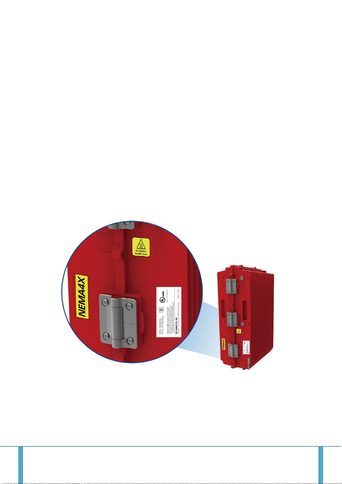
3) FCC Part 15.19
The FCC Certification label has attached right side of PS-ELITE7837. The FCC Certification label
contained FCC 15.19 warning statement, Device type (A or B), FCC and UL ID
This device complies with Part 15 of the FCC Rules. Operation is subject to the following two
conditions: (1) This device may not cause harmful interference, and (2) This device must accept any
interference received, including interference that may cause undesired operation.
GSTeletechinc 1
Page 5

4) FCC Part 90.219
Booster Warming Label is attached left side of PS-ELITE7837. This label has contains FCC 90.219, IC
warning statements and contact information for a trouble shooting.
① FCC Part 90.219 Class A (B9A)
“WARNING. This is NOT a CONSUMER device. It is designed for
installation by FCC LICENSEES and QUALIFIED INSTALLERS. You MUST
have an FCC LICENSE or express consent of an FCC Licensee to operate
this device. You MUST register Class A signal boosters (as defined in 47
CFR 90.219) online at www.fcc.gov/signal-boosters/registration.
Unauthorized use may result in significant forfeiture penalties, including
penalties in excess of $100,000 for each continuing violation.”
GSTeletechinc 2
Page 6
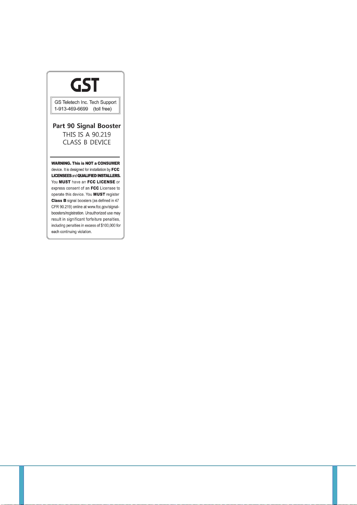
② FCC Part 90.219 Class B (B9B)
“WARNING. This is NOT a CONSUMER device. It is designed for
installation by FCC LICENSEES and QUALIFIED INSTALLERS. You MUST
have an FCC LICENSE or express consent of an FCC Licensee to operate
this device. You MUST register Class B signal boosters (as defined in 47
CFR 90.219) online at www.fcc.gov/signal-boosters/registration.
Unauthorized use may result in significant forfeiture penalties, including
penalties in excess of $100,000 for each continuing violation.”
5) FCC Part 90 Class B
Prior to equipment use the service must be registered with the FCC. This can be done through the
FCC’s website at https://signalboosters.fcc.gov/signal-boosters.
6) Radiation Exposure Statement
The product complies with the FCC Fixed RF exposure limit set forth for an uncontrolled environment
and is safe for intended operation as described in this manual. The further RF exposure reduction can
be achieved if the product can be kept as far as possible from the user's body or set the device to
lower output power if such a function is available.
7) FCC Part 90.635
Antennas must be installed in accordance with FCC 90.635. With 2.15dBi gain antennas the height of
the antenna above average terrain (HAAT) must not exceed 310.7 m. For different gain antennas refer
to the relevant rules.
GSTeletechinc 3
Page 7
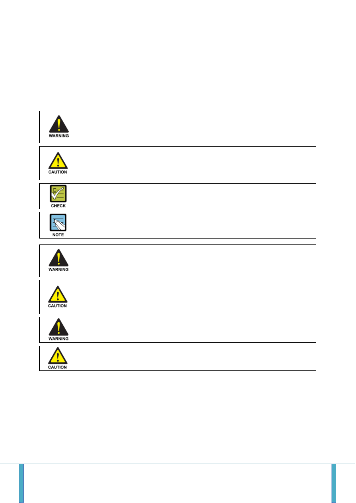
WARNING
Provides information or instructions that the reader should follow in order to avoid personal
injury or fatality
CAUTION
Provides information or instructions that the reader should follow in order to avoid
a service failure or damage to the system
CHECK POINT
Provides the operator with checkpoint for stable system operation
NOTE
Indicates additional information as a reference
No use for the unauthorized device
When installing the system. Must check the devices that use is authorized.
This conditions apply antenna, cable, and coupling device if necessary
Circuit Breaker Installation in the Box for Overcurrent Protection
Must install the circuit breaker between the system and main AC source for separating.
Make sure to install the Circuit breaker on the place to operate easily Circuit breaker be able to
operate up to 20A
Terminal, Conduit and Cable size
To install the conduit is according to NAE regulation, and Terminal size is according to NEC
regulation
Caution
Double Pole /Neutral fusing
2. Prohibitions
Use of unauthorized antennas, cables, and coupling devices not conform to ERP/EIRP and
indoor‐only restrictions is prohibited.
Preclude indications that Home/ personal use are prohibited.
2.1 Installation Warning statement
GSTeletechinc 4
Page 8

Certification
Type
ID
Remarks
FCC
B9A
U88-PSELITE37A
B9B
U88-PSELITE37B
3. General Information
This document is primarily written for those who are new to PS-LITE78A/B system and wish to tune up the
equipment. The document is applicable to below products from GSINSTECH. Model number: PS-ELITE78A/B
3.1 Repeater Information (FCC & ISED ID)
3.2 Purpose
PS-ELITE7837 Bi-Directional Amplifier (BDA) is a repeater, which has been designed to improve signals in
blanket/shadow areas inside of buildings to transmit Provider’s variety frequencies. User may choose filtering
configuration according to the specific site circumstances.
3.3 Repeater Advantages
It provides selectable RF power levels for any wireless technology / band.
It has individual monitoring multiple technology.
FPGA digital filtering provides optimized RF performance.
It allows modification of technology via customer interface.
It is easily installed.
Frequency is easy to add / delete / change.
It has scalable single and multi-service design.
Customer data service is improved by FirstNet
It meets all users’ technological requirements.
3.4 Highlights
Dual band support 700MHz and 800MHz band by WEB UI
Simultaneous Filter Supporting 1 Wide Band and 32 Non-Contiguous Narrow Bands
2W output power for each band
Fan-less
Significant Filter Roll-off performance
Supports Form 3 Dry Contact
External Alarm Function supporting Dry Contact
Digital/programmable utilizing FPGA
Auto shutdown with alarm upon oscillation detection
Web based GUI for intelligent configuration, SNMP supported
NFPA compliant dry contact alarms, NEMA 4x enclosure
GSTeletechinc 5
Page 9
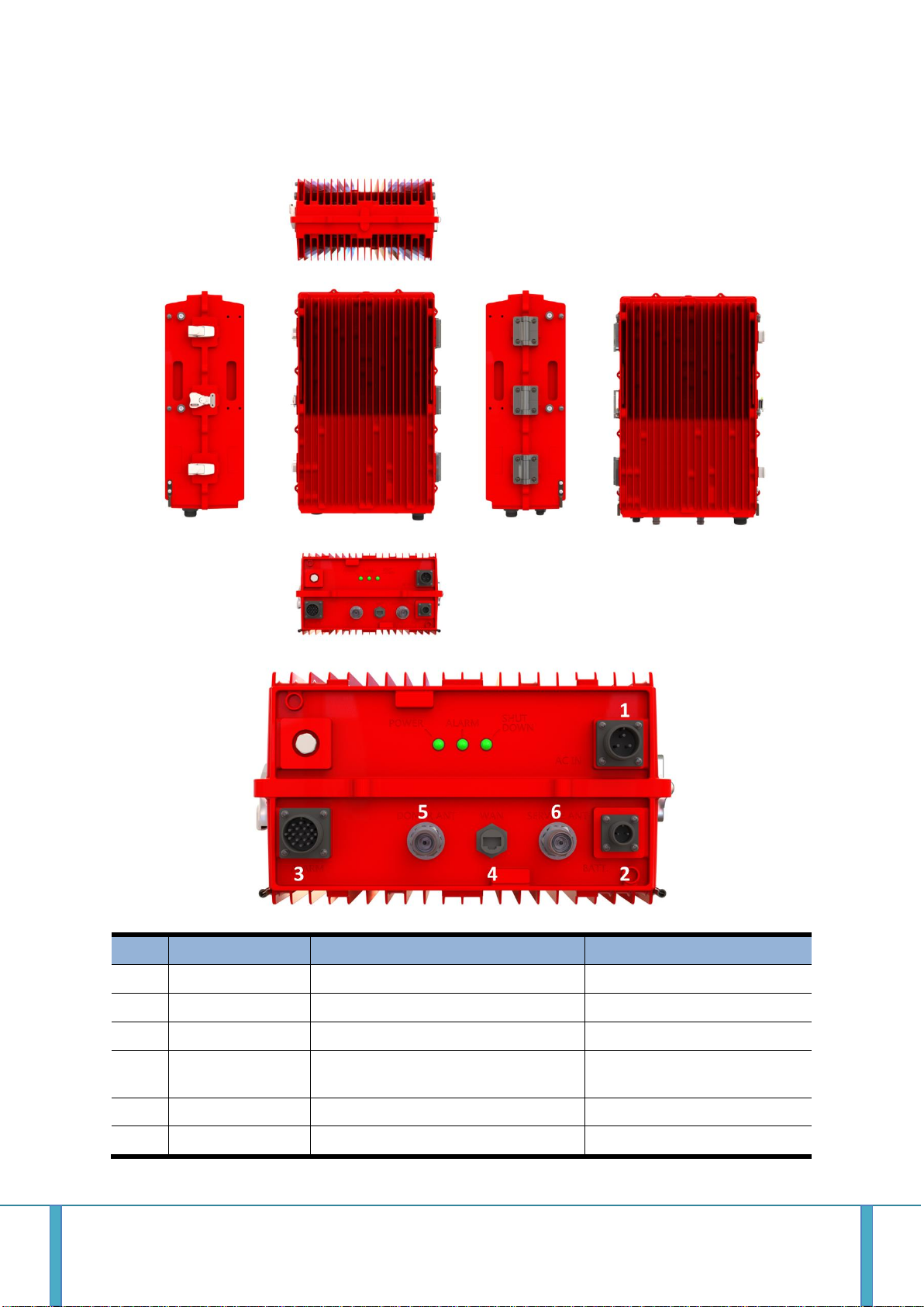
No
NAMES
DESCRIPTION
SPECIFICATION
1
AC IN
AC Power Input Port
MS-3102A-10SL-3P
2
Battery
Link to battery Backup Unit
Battery
3
External Alarm
Link to External Alarm Panel
4
Ethernet
Local Maintenance & Modem
Activation
Local: RJ-45
5
Donor ANT
Donor Antenna Connection
4.3-10 DIN Female
6
Service ANT
Service Antenna Connection
4.3-10 DIN Female
3.5 Exterior
GSTeletechinc 6
Page 10
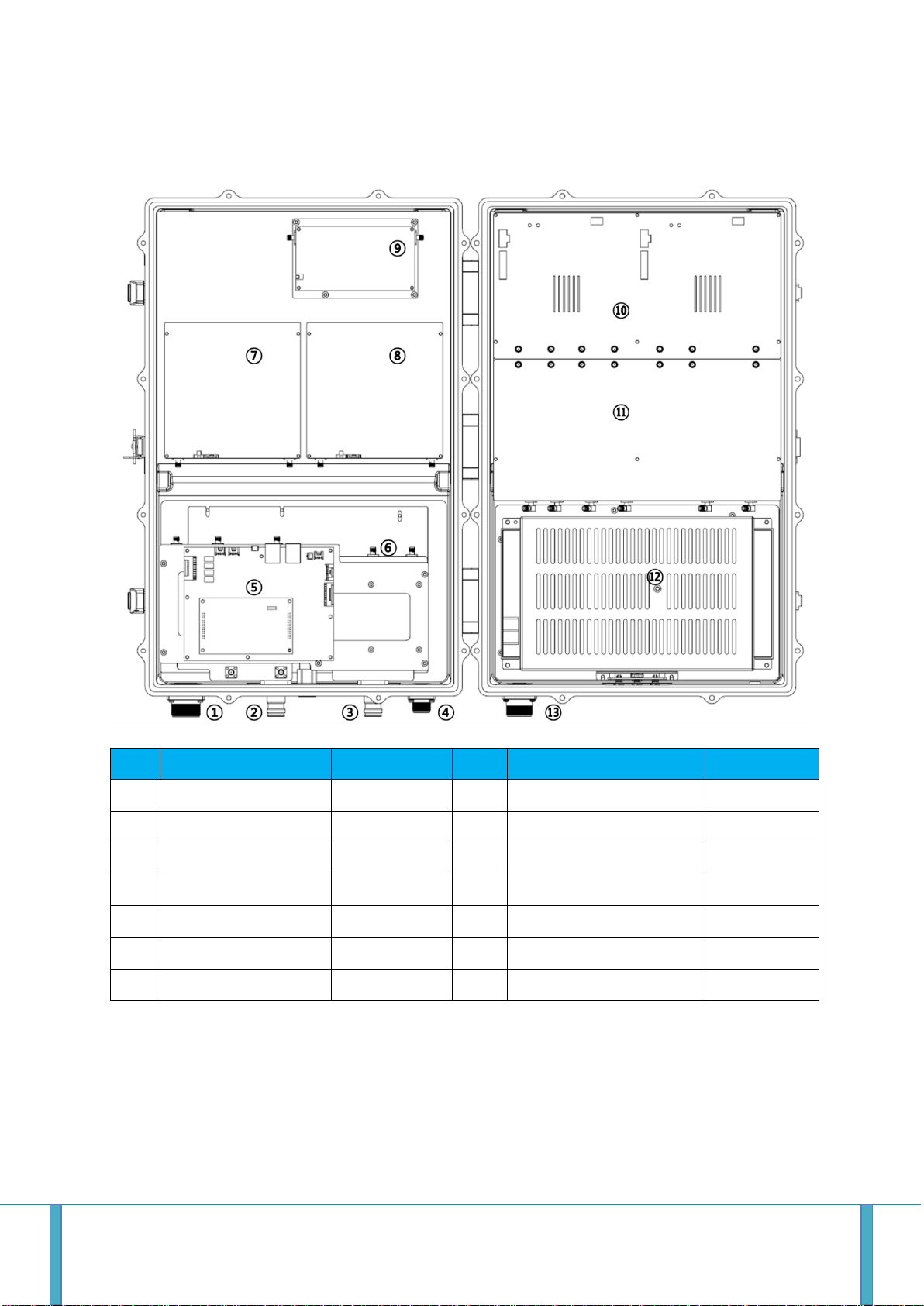
No.
Item
Remarks
No.
Item
Remarks
1
Ext. Alarm Connector
8 DL 700 HPA
2
Donor Antenna Port
9 UL HPA
3
Service Antenna Port
10
Digital Filter Module
4 Battery Backup Input
48V DC
11
RF Unit
5
I/O Board
12
PSU
6
Duplex Cavity Filter
13
AC Input Connector
110V AC Only
7
DL 800 HPA
3.6 Interior
PS-ELITE7837 consists of the following modules:
1) Donor / Service Antenna
All antenna ports use a 4.3-10 Din connector. If user wants to use an N-type cable, user must use a
separate adapter. (Not included)
2) Digital Filter Module & RF Unit
The integration module consists of RFU and DFM.
GSTeletechinc 7
Page 11

The RFU is assembled at the bottom of the integrated module, and performs amplification, filtering,
and gain control on the signal that passes through the duplexer.
The DFM is assembled on top of the integration module. DFM performs band select, band width
adjustment and power detection according to user setting.
3) Cavity Duplexer
Separation of input and output signals and isolation between paths
4) HPA Module
DL 700 HPA and DL 800 HPA are made up of different modules.
It amplifies the filtered and band selected signals via RFU and DFM, and maintains the output of the
system.
UL HPA provides 700M and 800M bands as one integrated module. It amplifies the filtered and band
selected signals via RFU and DFM, and maintains the output of the system.
5) PSU
The PSU supply power to the system.
The PSU receives 110V AC power and supplies + 28V DC and + 6V DC to the system. In the event of an
AC power failure, the system can be powered by receiving a -48V DC power through the battery. The
battery voltage input to the PSU should be -48V. If + 48V is used, the electrodes must be reversed
when connecting the battery. If the required battery voltage is not used or the electrode is not
suitable, the PSU may be damaged or not functioning normally.
The Company shall not be held liable for the problems caused by this.
6) I/O Board (Control Board)
The control board performs functions such as system control, communication. And alarm information
share through the external alarm connector.
System control and communication functions are available via the Web UI and SNMP via the system
RJ - 45 Port, Alarm Information Sharing is Ext. It can be connected to the External Alarm Panel via the
Alarm Connector for use.
7) Battery Backup Port
The system can use the battery backup system. In this case, the battery output should be +48V DC
User can’t be held responsible for any problems that arise from not following these recommendations
8) Ext. Alarm Connector
Ext. Alarm Connector is a port used to share alarm information generated by the system with external
alarm panel. Alarm information is shared through dry contact. Mapping between Alarm and Connect
can be confirmed by the following table.
9) WAN Network Port
The system supports Web UI or SNMP function through Ethernet to improve accessibility of external
network and user. To this end, the user can connect a cable to the RJ-45 connector.
Connectors and cables used should be waterproof.
10) Local Network
The system supports Web UI or SNMP function through Ethernet to improve accessibility of internal
network and user. To this end, the user can connect a cable to the RJ-45 connector.
11) AC Input Connector
The input voltage of system is only 110V AC and the voltage input such as 220V AC is not approved.
No liability or compensation shall be required by the Company for problems caused by not permitted
input AC voltage.
GSTeletechinc 8
Page 12

Item
Specification
Remark
Down Link
Frequency
700 (PSBB)
758MHz ~ 768MHz
LTE
700 (PSNB)
769MHz ~ 775MHz
P25
800 (PSNB)
851MHz ~ 861MHz
P25
Up Link
Frequency
700 (PSBB)
788MHz ~ 798MHz
LTE
700 (PSNB)
799MHz ~ 806MHz
P25
800 (PSNB)
806MHz ~ 816MHz
P25
4. Specifications
4.1 US Frequency Allocation
4.1.1 US frequency
4.1.2 US Service Plan
1) The LTE network integrates Upper D band and FirstNet to have max. 10MHz Service BW.
2) The P25 Network has a Guard Band of 768-769MHz and 775-776MHz.
GSTeletechinc 9
Page 13

Item
Specification
Remark
Select
Bandwidth
PSBB – LTE
5 / 10MHz
PSNB – B9A
6.25 / 12.5 / 25 / 50 / 75KHz
PSWB – B9B
100 / 125 / 150 / 175 / 200 / 225 / 250KHz
DL
Output Power
LTE (PSBB)
+34dBm / 2.5W (@total)
+37dBm / Total
700 (PSNB)
+34dBm / 2.5W (@total)
800 (PSNB)
+37dBm / 2W (@total)
UL
Output Power
LTE (PSBB)
+30dBm / 1W (@total)
+33dBm / Total
700 (PSNB)
+30dBm / 1W (@total)
800 (PSNB)
+33dBm / 2W (@total)
Max RF Input Power without
-17dBm
@ Over Drive
Max RF Input Power without
+10dBm
@ No Damage
Gain
DL Range
54dB ~ 99dB
ALC: 45dB
UL Range
50dB ~ 95dB
Adjust Step
±1.0dB
Adjust Accuracy
±1.0dB
Propagation
Delay
LTE
< 6us
PSNB
< 230us
Adjacent
Channel Power
LTE
> 45dBc @ ± 5M
> 50dBc @ ± 10M
PSNB
> 50dBc @ Ch Offset 25kHz
> 50dBc @ Ch Offset 50kHz
Flatness
< 3dB
Return Loss / VSWR
< -14dB /< 1.5 : 1
Noise Figure
< 5dB @ Max gain
Uplink Only
EVM
≤ 8%
(E-TM3.1 / DL : 64QAM, UL 16 : QAM)
LTE Only
Roll Offs
LTE
>55dBc @ ±1MHz
outside pass-band
PSNB
>55dBc @ ±6.25KHz or
>55dBc @ ± ½ Bandwidth
Characteristic Impedance
50Ω
4.2 Common Specifications
GSTeletechinc 10
Page 14
Item
Specification
Remark
RF Connector
Mini DIN (4.3-10) Type Female
AC Power Connector
MS3102A 20SL-3P
AC Power Cord
MS3106A-20SL-3S
Battery Backup Connector
MS3102A-14S-9P
External Alarm Connector
MS3102A-22-14P
External Interface
RJ-45 / USB A Type
Waterproof
Alarm Interface
Dry Contact
20Pin
AC Supply
110VAC ~ 120VAC, 60Hz 2.0A
±10%
DC Supply
48V
Out Dimension
19" x 13.2" x 7.8"
480mm x 335mm x 200mm
Net Weight
Max. 68 lb
30kg
Material
Module
Aluminum alloy
Cabinet
Aluminum alloy for casting
Operation Temperature
-40°F to +122°F (-40°C to +50°C)
Convection cooling
Storage Temperature
-40°F to +185°F (-40°C to +85°C)
Humidity
5% ~ 95%
Non-Condensing
Environmental Spec.
NEMA4x
IP668
MTBF
100,000
hour
4.3 Mechanical Spec.
GSTeletechinc 11
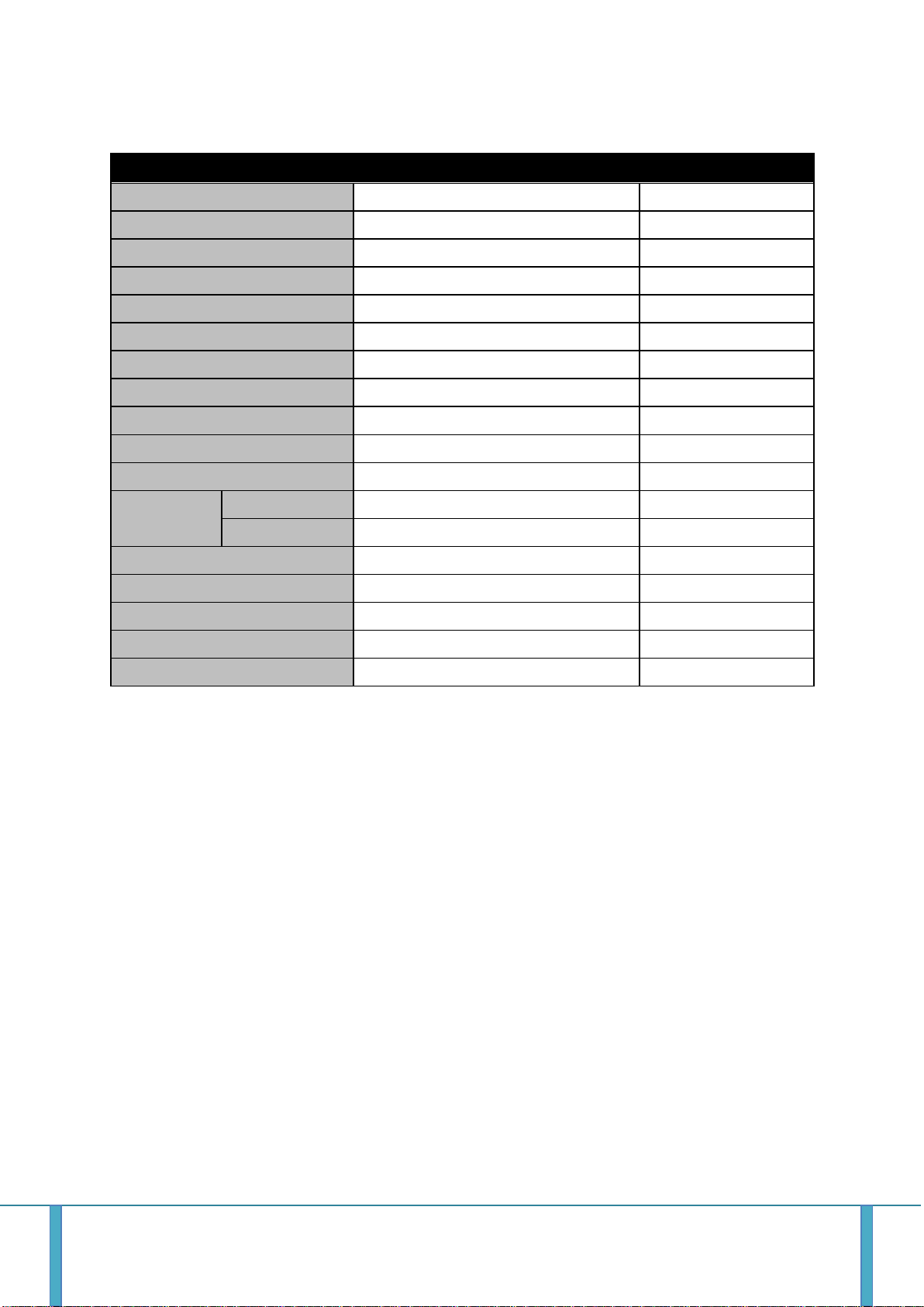
Page 15

Pin No.
Pin Name
Cable Color
Remarks
1 +
Red(or White)
2 -
Black
5. Port and Connectors
5.1 RF Connector
PS-ELITE7837 adopts a Mini-DIN 4.3/10 connector. If the user wants to use an N type cable or connector, they
need an adapter.
5.2 AC Power Connector
PS-ELITE 7837 use only 110V voltage. If the user uses other unrecommend input voltages, PS-ELITE7837 may be damaged. The AC
Power Connector of the PS-ELITE 7837 uses CAR3102A-20-3P and the
user shall use a cable equipped with a cable CAR3106A-20-3S connector
to terminate the power.
5.3 DC Battery Power Connector
PS-ELITE 7837 use a 48V battery only. If the user uses other nonstandard input voltages, PS-EILITE7837 may be
broken or damaged. If the user want to use a +48V battery, it is acceptable to cross the input electrode.
GSTeletechinc 12
Page 16

Pin No.
Alarm No.
Alarm Name
Pin Name
Cable Color
Remarks
A
Alarm1
AC
Power
N.C 1
Black
B
COM 1
Brown
C
N.O 1
Red
D
Alarm2
BDA
N.C 2
Orange
E
COM 2
Yellow F
N.O 2
Green
G
Alarm3
Reserved
N.C 3
Blue
H
COM 3
Violet I
N.O 3
Gray J
Alarm4
Reserved
N.C 4
White K
COM 4
Black & Line
L
N.O 4
Brown & Line
M
Alarm5
Reserved
N.C 5
Red & Line
N
COM 5
Orange & Line
P
N.O 5
Yellow & Line
R
Alarm6
Reserved
N.C 6
Green & Line
S
COM 6
Blue & Line
T
N.O 6
Violet & Line
U
Reserved
Gray & Line
5.4 External Alarm Port (Dry-Contact)
PS-ELITE7837 supports the External Alarm Box. The external alarm box is
connected via the External Alarm Connector. The External Alarm Box of PSELITE 7837 is configured using the Dry Contact.
The connection between the External Alarm Port and the External Alarm
Box is made using the UL2464 # 24 10ft cable supplied with the system.
1) PS-ELITE support external Alarm Box
N.C : Normal Close / N.O : Normal Open
GSTeletechinc 13
Page 17

LED
Status
Remarks
Green
Good Condition, The system operates normally.
Red
Critical alarm, Unable to operate properly
Name
RUN
ALARM
SHUTDOWN
Power On
Green
Boot Complete
Green
Green
Green
Normal Condition
Green
Green
Green
Over Power
Green
Green
Red
AC Fail
Green
Green
Red
DC Fail
Green
Green
Red
RESET
Green
Red
Red
Shut Down
Red
Red
Red
5.5 Ethernet Port
PS-ELITE 7837 can be connected to the parent network via Ethernet, and the user can use the WEB UI to
control and monitor the relays in remote or local locations. PS-ELITE 7837 use a waterproof Ethernet port to
prevent the external environment from being affected. (NEMA 4x Compliance)
For complete waterproofing, the user shall use a water-proof RJ-45 cable.
6. LED and Alarm Information
6.1 LED
6.2 LED indicate for alarm
GSTeletechinc 14
Page 18

Parameter
Item
Quantity
Remark
Major Component
PS-ELITE7837 Repeater
1 EA
Provided by GST
Additional Components
Wall Mounting Bracket
1 EA
Provided by GSI
AC Power Cable 1.8m
1 EA
DC Power Cable 2m
1 EA
External Alarm Cable 2 m
1 EA
Antenna
Donor ANT
1 EA
Not Included
Service ANT
1 EA
RF Cable
Antenna connection Cable
TBD
Not Included
Testing and Measuring
Equipment
Spectrum Analyzer
1 EA
Not Included
7. Installation
7.1 Installation
7.1.1 Antenna
1) The antenna used in the PS-ELITE7837 must be certified or an antenna with equivalent specifications.
2) Antenna gain is restricted to “Cable loss+2.15dB”
3) The company shall not bear any liability for any problems arising from the use of an uncertified
antenna.
7.1.2 Isolation
If the system wants to operate in the max gain state, the system requires sufficient isolation between
the donor and service antennas.
The system recommends isolation be higher than 15dB above the gain of the system.
If isolation is not sufficiently ensured, the AOC function operates to reduce the gain to a level suitable
for the ensured isolation.
7.1.3 Equipment Needed for Repeater Setup
7.1.4 Check points before turning on the Repeater
1) System Power Check
2) Input RF Signal Range
3) Isolation check between DONOR/SERVEICE ANT
7.1.5 Open for Service
1) Check points before open:
GSTeletechinc 15
AC electrical power to the repeater should be 110V, input electricity only after power verification.
Optimal input RSSI into the repeater is -62dBm ~ -17dBm for 700MHz/800MHz. User should verify
input condition of Donor ANT. If the input RSSI exceeds -17dBm, impose the using external
attenuators should be used.
The system must need that 114dB (Gain+15dB) isolation is secured to use 99 dB of the maximum
profit of the system. User should check its condition before installation.
① Verification of system installation status :
Electricity, In/Out antennas, cable connection, and equipment mount status.
② Verification of system accessories :
User should check all necessary accessories.
Page 19

③ Check receipt signal level :
Installer should check whether environmental conditions are in accordance with system
specification to ensure that system operation will be optimized.
2) Check points after open:
① Check external LED
RUN: Green light ON (Off: All LED off)
ALARM: Green light in normal status, Red light in alarming
SHUT DOWN: Green light in normal status, Red light in Shutdown status
7.2 Ground
The PS-ELITE7837 is designed to operate at 110VAC @ 1.5A maximum current and must always be operated
with the ground wire properly connected.
GSTeletechinc 16
Page 20

8. Web UI
8.1 Setting up the Repeater
8.1.1 Quick UI/Configuration
Use the following steps to commission the Repeater after all the cabling and antennas are fixed in
place and the Repeater is supplied with proper electrical power. The repeater will need a good
quality stable Downlink RSSI input level in the range of -85dBm to -62dBm.
1) Connect your laptop to the repeater with a Crossover Ethernet cable.
2) Verify that your laptop has all wireless connections off and is Obtaining an IP address automatically,
or is using a proper fixed IP address such as: Use the following IP address: 192.168.2.1 with a Subnet
Mask of 255.255.255.0
3) Open Internet Explorer and go to: 172.16.6.81
4) User name: admin
5) Password: admin
8.1.2 Quick Setup
1) Go to the RF Configuration page.
2) Before the Amplifier (HPA) can be turned on, set the Uplink and Downlink attenuation (ATT) to the
maximum value and click Apply.
3) Select the correct Band Block and set the ALC Downlink and Uplink Limits to the desired level and
click Apply. (To adjust the Output Power, change the ALC Downlink and Uplink Limits to the desired
levels).
4) To check the Repeater’s status, click on the Status page.
5) To change the Repeater’s gain/attenuation, adjust the Uplink and Downlink attenuation in equal
amounts not more than 5dB at a time and click Apply.
GSTeletechinc 17
Page 21

8.2 User Interface Configuration
8.2.1 Log in the Web-UI
1) Configuring the Laptop to connect
2) Enter the IP Address "192.168.2.1" into your browser address bar
8.2.2 Page Login
Figure 1. Laptop Configuration for connecting the Web-UI
1) Access the portal by going to http://192.168.2.1
2) Sign in with username “admin” and Password “admin”
8.2.3 Log Out
1) Please logout of device once done viewing device information
GSTeletechinc 18
Page 22
GSTeletechinc 19
Page 23

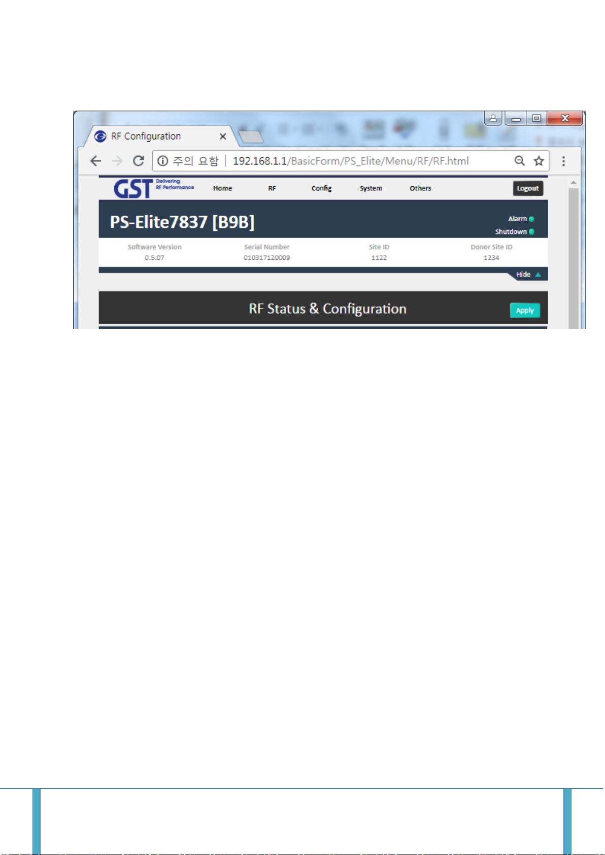
8.2.4 RF Status & Configration
1) Can check the current repeater status and setting the repeater system.
2) Items
Check of RSSI / Output Level
ALC Index, ALC On/Off, ALC Attn., AMP On/Off
AOC On/OFF, AOC DET, AOC CurrentAttn.
FirstNet (LTE) Band Select (Frequency and Bandwidth)
700MHz P25 Band Select (Frequency and Bandwidth)
800MHz P25 Band Select (Frequency and Bandwidth)
Shutdown On/Off Select
8.2.5 Alarm Configuration
GSTeletechinc 20
Page 24

1) Check the status and status of the alarm on the repeater.
GSTeletechinc 21
Page 25

8.2.6 Fake Alarm Configuration
1) Set alarm for testing purposes.
GSTeletechinc 22
Page 26

8.2.7 Communication Configuration
Set up the IP information for the network management communication.
8.2.8 System Log
Can view the log in connect to the WEB UI.
GSTeletechinc 23
Page 27

GSTeletechinc 24
Page 28
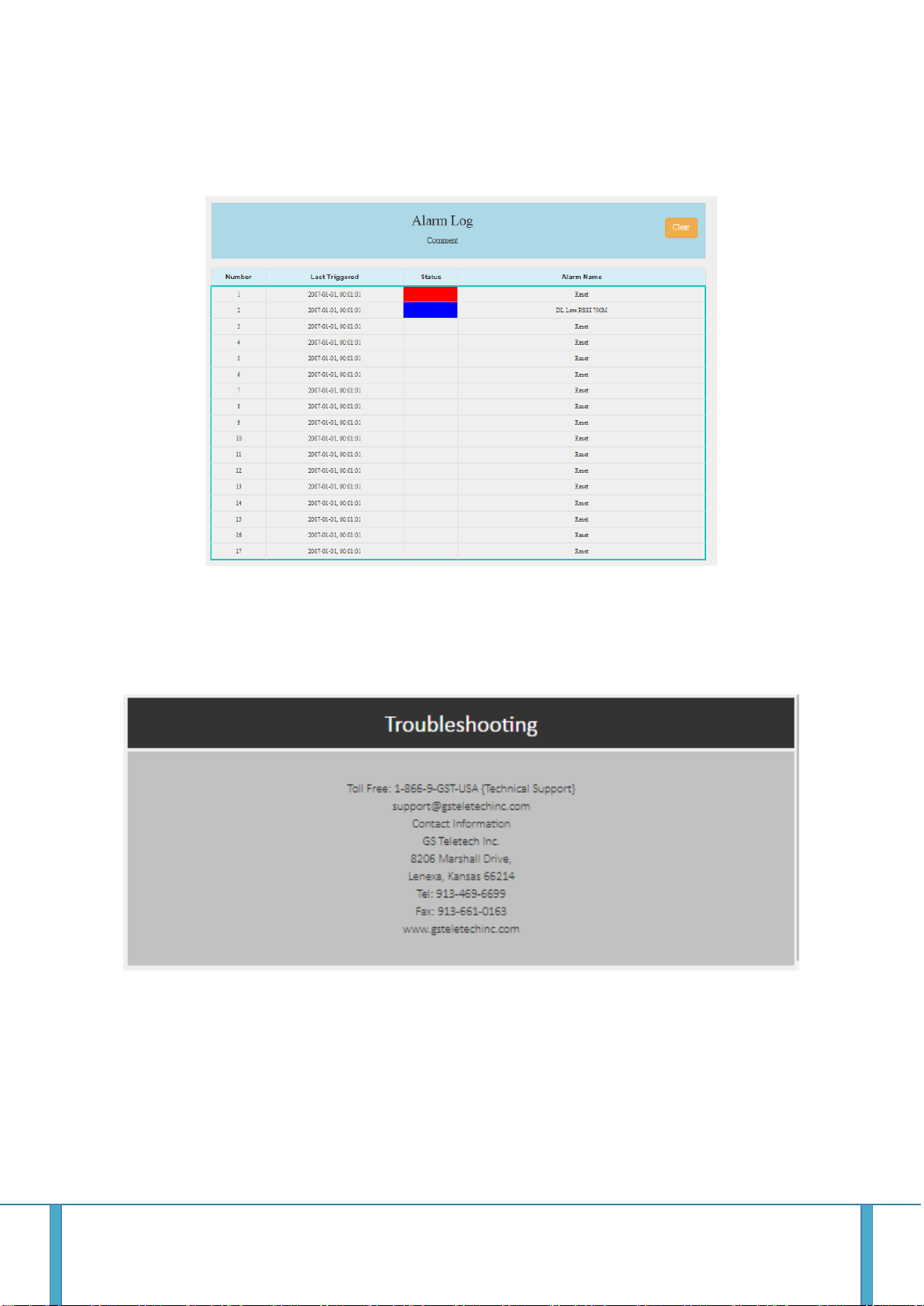
8.2.9 Alarm Log
Record the log on the alarm that occurred on the repeater.
8.2.10 Trouble Shooting
Provide contact information to assist in trouble shooting in the event of a repeater failure
GSTeletechinc 25
Page 29
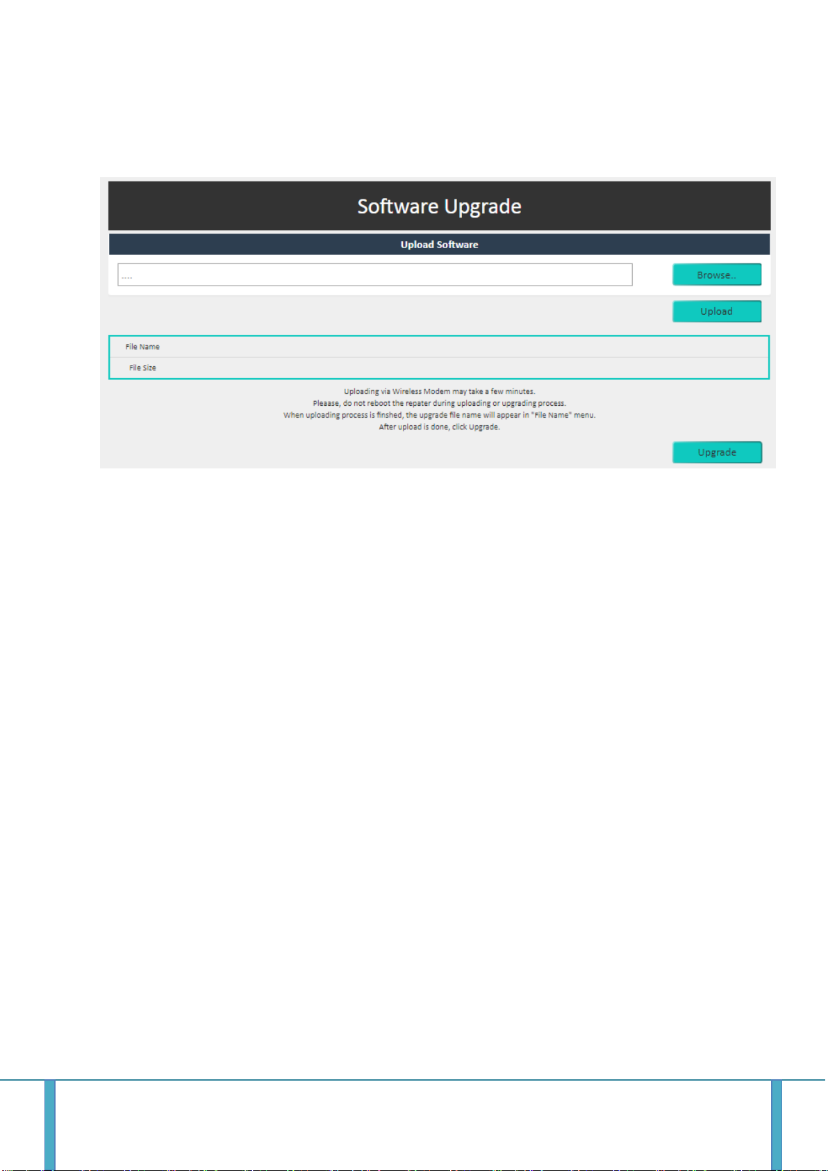
8.2.11 Remote Software Upgrade
To enhance the performance of the repeater, perform the Software Upgrade through the network.
1) Select the file to upgrade and upload the file to the repeater's memory.
2) If the file is successfully uploaded, click the Update button to proceed with the upgrade.
GSTeletechinc 26
Page 30

8.2.12 User Management
Manage user accounts to login to WEB UI.
1) Password Change
2) User account Permission authorization and change
3) New account setting
GSTeletechinc 27
Page 31

8.2.13 Factory Default Setting
The factory default setting is the default setting of the repeater that is controlled by the company.
When performing a factory-defined setting, the L status set is initiated by the user.
8.2.14 System Reset
You can system reset by WEB-UI
GSTeletechinc 28
 Loading...