

Page 1

Version
1.0
Date
NOV. 27, 2018
Page
1/ 42
Title
USER MANUAL
Prepared by
KO. SUNGMOO
Reviewed by
Approved by
USER MANUAL
PSD-LI27
PSS-LI33 / PSS-LI37
NOV. 27, 2018
GS Instech Co., Ltd.
© 2018 GS Instech Co., Ltd. All rights reserved.
1
Page 2

Version
1.0
Date
NOV. 27, 2018
Page
2/ 42
Title
USER MANUAL
Prepared by
KO. SUNGMOO
Reviewed by
Approved by
DATE
NAMES
DESCRIPTIONS
VERSION
REMARK
NOV 17, 2018
KO. SUNGMOO
Original Draft
1.0
DEC 27, 2018
KO. SUNGMOO
Add Label Information
1.1
[CHANGE RECORD]
© 2018 GS Instech Co., Ltd. All rights reserved.
2
Page 3
Version
1.0
Date
NOV. 27, 2018
Page
3/ 42
Title
USER MANUAL
Prepared by
KO. SUNGMOO
Reviewed by
Approved by
CHAPTER’s INDEX
[TABLE OF CONTENTS]
1. GENERAL ........................................................................................................................................... 6
1.1. Purpose ............................................................................................................................................. 6
1.2. Copyright .......................................................................................................................................... 6
1.3. FCC Warning Statements .................................................................................................................. 6
1.3.1 FCC Part 15.105 ........................................................................................................................... 10
1.3.2 FCC Caution ................................................................................................................................. 10
1.3.3 Radiation Exposure Statement .................................................................................................... 10
1.3.4 FCC Warning Labels ..................................................................................................................... 10
1.4. Antenna installation ........................................................................................................................ 11
2. INTRODUCTION............................................................................................................................... 12
2.1. System Overview ............................................................................................................................ 12
2.2. Main Features ................................................................................................................................. 13
3. SYSTEM DESIGN FOR PSD-LI27 (DONOR UNIT) .............................................................................. 14
3.1. Exterior View .................................................................................................................................. 14
3.2. Interior View ................................................................................................................................... 15
3.3. External Interface ........................................................................................................................... 17
4. SYSTEM DESIGN FOR PSS-LI33 (SERVICE UNIT) .............................................................................. 18
4.1. Exterior View .................................................................................................................................. 18
4.2. Interior View ................................................................................................................................... 19
4.3. External Interface ........................................................................................................................... 20
5. SYSTEM DESIGN FOR PSS-LI37 (SERVICE UNIT) .............................................................................. 21
5.1. Exterior View .................................................................................................................................. 21
5.2. Interior View ................................................................................................................................... 22
5.3. External Interface ........................................................................................................................... 23
6. SYSTEM SPECIFICATION .................................................................................................................. 24
6.1. RF Performance .............................................................................................................................. 24
6.2. Frequency Information ................................................................................................................... 25
6.2.1. Frequency Information ................................................................................................................ 25
6.2.2. Block Diagram .............................................................................................................................. 25
6.2.3. Service Plan ................................................................................................................................. 26
6.3. Configuration & Mechanical Specification ..................................................................................... 27
© 2018 GS Instech Co., Ltd. All rights reserved.
3
Page 4
Version
1.0
Date
NOV. 27, 2018
Page
4/ 42
Title
USER MANUAL
Prepared by
KO. SUNGMOO
Reviewed by
Approved by
FIGURE’s INDEX
7. SYSTEM BLOCK CONFIGURATION ................................................................................................... 29
7.1. Block Diagram ................................................................................................................................. 29
8. GUI OVERVIEW ............................................................................................................................... 31
8.1. Configuration the Laptop to Connect to the Repeater ................................................................... 31
8.2. Login-In Screen ............................................................................................................................... 32
8.3. Main Screen ....................................................................................................................................................
8.4. RF Status ......................................................................................................................................... 33
8.5. RF Configuration ............................................................................................................................. 34
8.6. Band Selection ................................................................................................................................ 35
9. SYSTEM INSTALLATION .................................................................................................................... 36
9.1. Warnings and Hazards .................................................................................................................... 37
9.1.1. Electric Shock .............................................................................................................................. 37
9.1.2. Exposure to RF ............................................................................................................................. 37
9.2. Service Man Installation Guide ....................................................................................................... 38
9.2.1. Wall Mount Installation ........................................ ...........
9.3. Cable Connection ............................................................................................................................ 41
9.3.1. DC Power cable connection ......................................................................................................... 41
9.3.2. Local Maintenance Connection ................................................................................................... 41
9.3.3. ......................................................................................................................................................... 41
9.3.4. Grounding cable Connection ....................................................................................................... 42
FIGURE 1FCC/ UL CERTIFICATION STATEMENT .......................................................................................................................................................... 8
FIGURE 2. PS-DAS APPLICATION CONFIGURATIONS .............................................................................................................................................. 12
FIGURE 3. PSD-LI27 EXTERIOR VIEW ......................................................................................................................................................................... 14
FIGURE 4. PSD-LI27 INTERIOR VIEW .......................................................................................................................................................................... 15
FIGURE 5. PSD-LI27 EXTERNAL INTERFACE .............................................................................................................................................................. 17
FIGURE 6. PSS-LI33 EXTERIOR VIEW .......................................................................................................................................................................... 18
FIGURE 7. PSS-LI33 INTERIOR VIEW .......................................................................................................................................................................... 19
FIGURE 8.PSS-LI33 EXTERNAL INTERFACE ................................................................................................................................................................ 20
FIGURE 9. PSS-LI37 EXTERIOR VIEW .......................................................................................................................................................................... 21
FIGURE 10. PSS-LI37 INTERIOR VIEW ........................................................................................................................................................................ 22
FIGURE 11. PSS-LI37 EXTERNAL INTERFACE ............................................................................................................................................................ 23
© 2018 GS Instech Co., Ltd. All rights reserved.
4
Page 5
Version
1.0
Date
NOV. 27, 2018
Page
5/ 42
Title
USER MANUAL
Prepared by
KO. SUNGMOO
Reviewed by
Approved by
TABLE’s INDEX
FIGURE 12. SYSTEM BLOCK DIAGRAM ...................................................................................................................................................................... 25
FIGURE 13. 700MHZ BAND ALLOCATION ................................................................................................................................................................. 26
FIGURE 14. 800MHZ BAND ALLOCATION ................................................................................................................................................................. 26
FIGURE 15. PSD-LI27 BLOCK DIAGRAM CONFIGURATION ................................................................................................................................... 29
FIGURE 16. PSS-LI33 / 37 BLOCK DIAGRAM CONFIGURATION ........................................................................................................................... 29
FIGURE 17. THE WAY TO FIX FIRMLY THE SYSTEM FOR POLE MOUNTING ...................................................................................................... 38
FIGURE 18.THE WAY TO FIX FIRMLY THE SYSTEM FOR WALL MOUNTING ....................................................................................................... 40
TABLE 1. PSD-LI27 UNIT CONFIGURATION ............................................................................................................................................................... 16
TABLE 2. PSD-LI27 EXTERNAL INTERFACE DESCRIPTION ...................................................................................................................................... 17
TABLE 3. PSS- LI33 UNIT CONFIGURATION ............................................................................................................................................................... 19
TABLE 4. PSS-LI37 EXTERNAL INTERFACE DESCRIPTION ....................................................................................................................................... 20
TABLE 5. PSS- LI37 UNIT CONFIGURATION ............................................................................................................................................................... 22
TABLE 6. PSS-LI37 EXTERNAL INTERFACE DESCRIPTION ....................................................................................................................................... 23
TABLE 7. PS-DAS RF PERFORMANCE DESCRIPTION ............................................................................................................................................... 24
TABLE 8.PS-DAS FREQUENCY ALLOCATION .............................................................................................................................................................. 25
TABLE 9. PS-DAS MODULE FREQUENCY INFORMATION ....................................................................................................................................... 25
TABLE 10. PS-DAS CONFIGURATION & MECHANICAL SPECIFICATION .............................................................................................................. 27
TABLE 11. PS-DAS INSTALLATION ACCESSORIES ..................................................................................................................................................... 36
© 2018 GS Instech Co., Ltd. All rights reserved.
5
Page 6

Version
1.0
Date
NOV. 27, 2018
Page
6/ 42
Title
USER MANUAL
Prepared by
KO. SUNGMOO
Reviewed by
Approved by
1. General
1.1. Purpose
This document introduces features, specifications, structures and operation guideline
for the PSD-LI27/PSD-LI33/LI37.
1.2. Copyright
All text and image in this document are subject to the copyright of GS Instech Co., Ltd.
This document may not be reproduced, distributed, or modified without the written permission of GS Instech
Co., Ltd.
1.3. FCC Warning Statements
FCC Warning Statement for system is follows. Must attach the label under manufacturing.
© 2018 GS Instech Co., Ltd. All rights reserved.
6
Page 7
Version
1.0
Date
NOV. 27, 2018
Page
7/ 42
Title
USER MANUAL
Prepared by
KO. SUNGMOO
Reviewed by
Approved by
© 2018 GS Instech Co., Ltd. All rights reserved.
7
Page 8
Version
1.0
Date
NOV. 27, 2018
Page
8/ 42
Title
USER MANUAL
Prepared by
KO. SUNGMOO
Reviewed by
Approved by
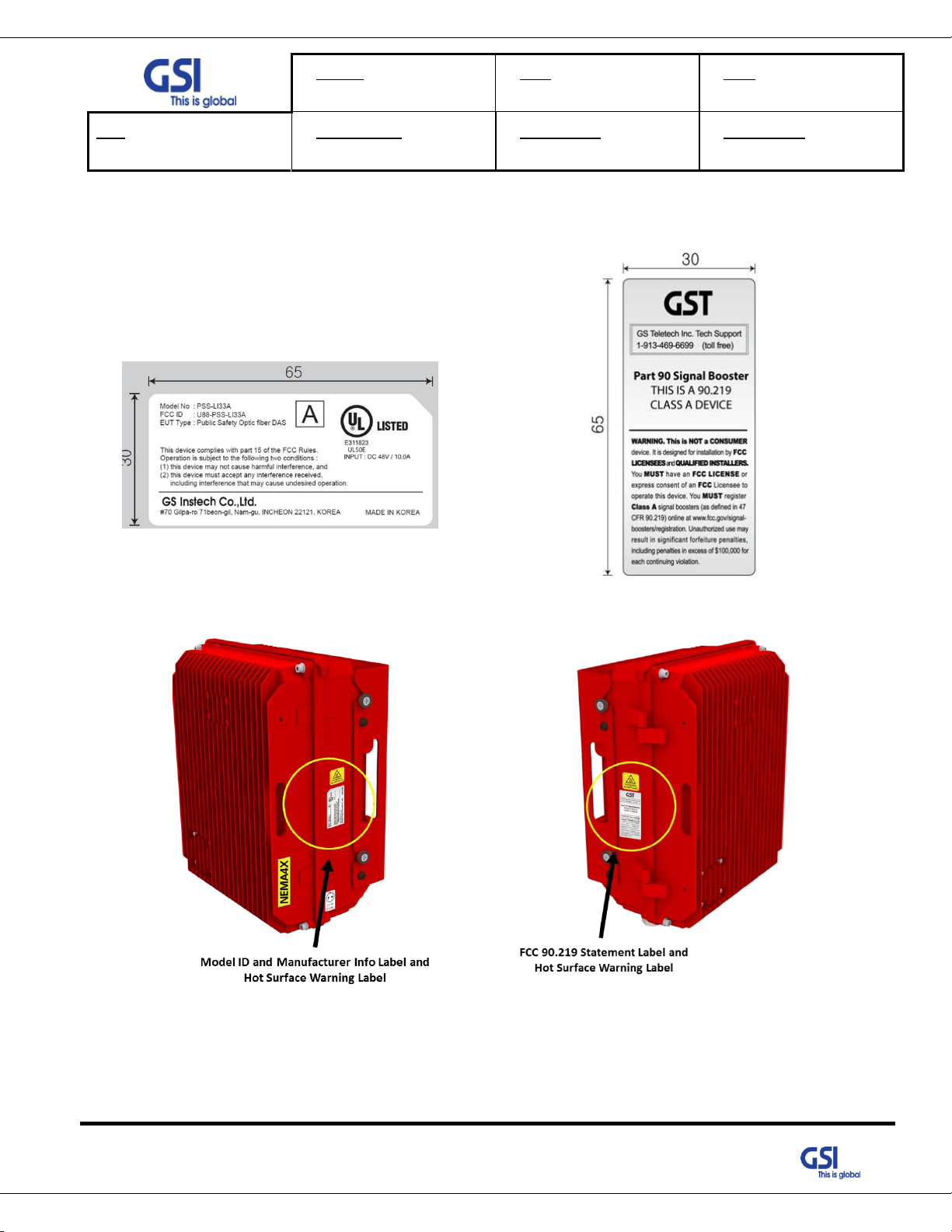
Figure 1. FCC/ UL Certification Statement [Class A]
© 2018 GS Instech Co., Ltd. All rights reserved.
8
Page 9
Version
1.0
Date
NOV. 27, 2018
Page
9/ 42
Title
USER MANUAL
Prepared by
KO. SUNGMOO
Reviewed by
Approved by
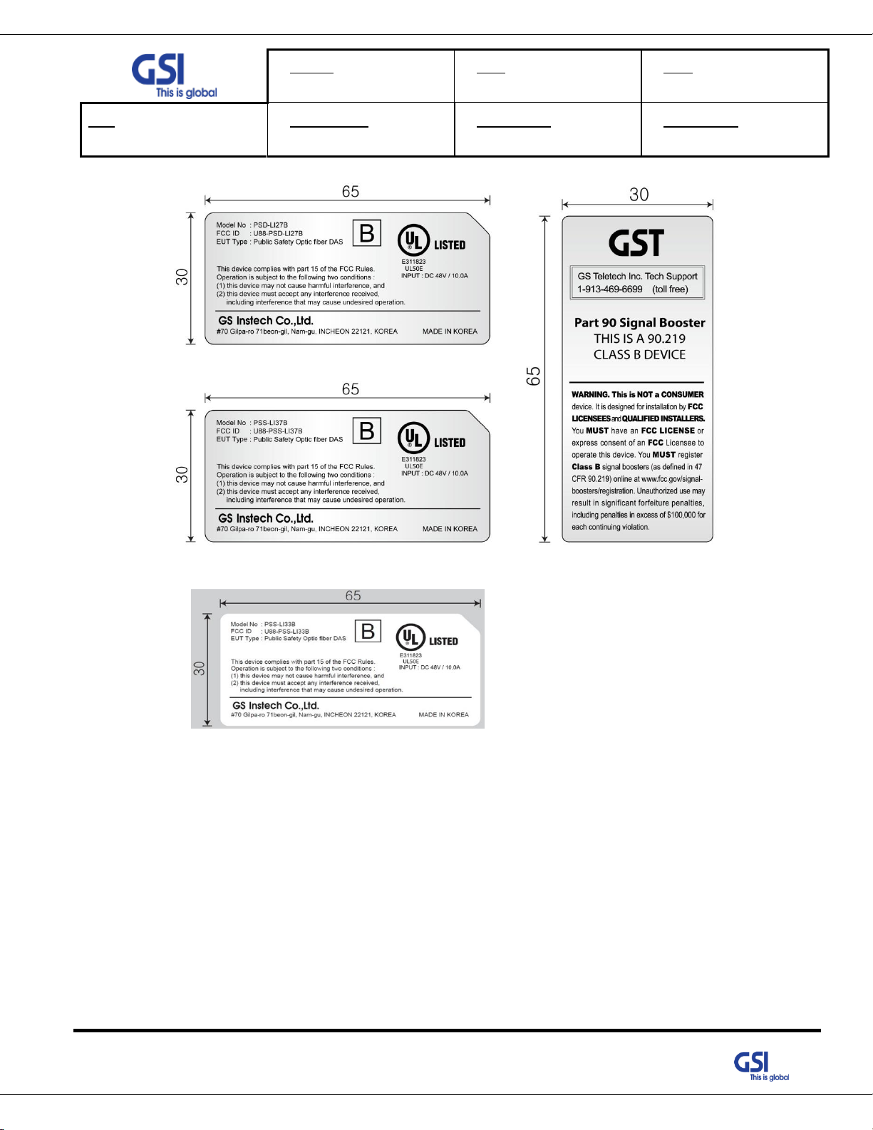
Figure 2. FCC/ UL Certification Statement [Class B]
The user’s manual or instruction manual for an intentional or unintentional radiator shall caution the user that changes
or modifications not expressly approved by the party responsible for compliance could void the user's authority to
operate the equipment. In cases where the manual is provided only in a form other than paper, such as on a computer
disk or over the Internet, the information required by this section may be included in the manual in that alternative
form, provided the user can reasonably be expected to have the capability to access information in that form.
© 2018 GS Instech Co., Ltd. All rights reserved.
9
Page 10
Version
1.0
Date
NOV. 27, 2018
Page
10/ 42
Title
USER MANUAL
Prepared by
KO. SUNGMOO
Reviewed by
Approved by
1.3.1 FCC Part 15.105
This equipment has been tested and found to comply with the limits for a Class A digital device, pursuant to part
15 of the FCC Rules. These limits are designed to provide reasonable protection against harmful interference when
the equipment is operated in a commercial environment. This equipment generates, uses, and can radiate radio
frequency energy and, if not installed and used in accordance with the instruction manual, may cause harmful
interference to radio communications. Operation of this equipment in a residential area is likely to cause harmful
interference in which case the user will be required to correct the interference at his own expense.
1.3.2 FCC Caution
Any changes or modifications not expressly approved by the party responsible for compliance could void the user's
authority to operate this equipment. This transmitter must not be co-located or operating in conjunction with any
other antenna or transmitter. Use of unauthorized antennas, cables, and/or coupling devices not conforming with
ERP/EIRP and/or indoor‐only restrictions is prohibited.
1.3.3 Radiation Exposure Statement
The product complies with the FCC RF exposure limit set forth for an uncontrolled environment and is
safe for intended operation as described in this manual. The further RF exposure reduction can be achieved if the
product can be kept as far as possible from the user's body or set the device to lower output power if such a
function is available.
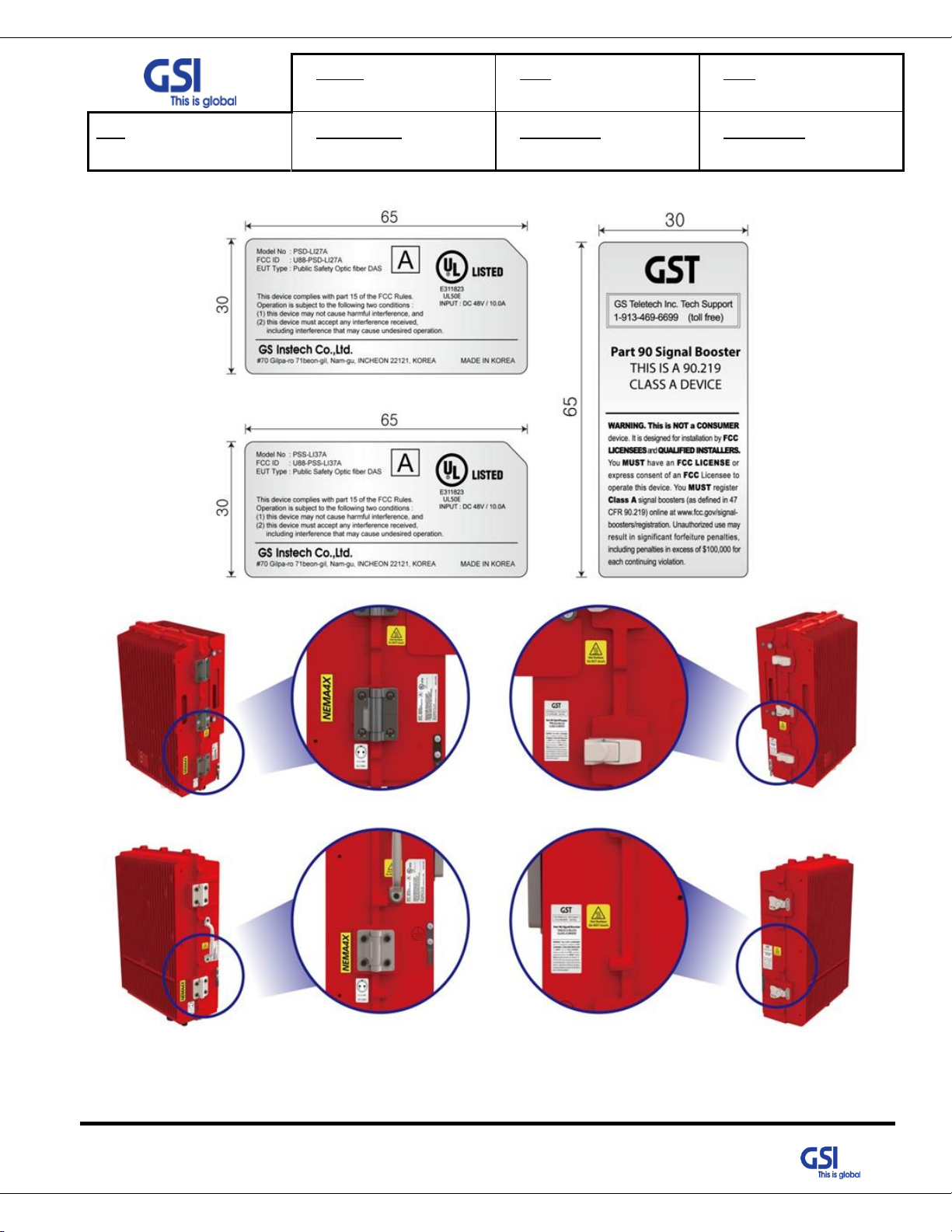
1.3.4 FCC Warning Labels
1) FCC Part 15.19
The FCC Certification label has attached right side of the device. The FCC Certification label contained FCC
15.19 warning statement, Device type (A or B), FCC, ISED and UL ID
This device complies with Part 15 of the FCC Rules. Operation is subject to the following two conditions: (1)
This device may not cause harmful interference, and (2) This device must accept any interference received,
including interference that may cause undesired operation.
2) FCC Part 90.219
Booster Warming Label is attached left side of the device. This label has contains FCC 90.219, IC warning
statements and contact phone number for a trouble shooting.
3) FCC Part 90 Class B
Prior to equipment use the service must be registered with the FCC.
This can be done through the FCC’s website at https://signalboosters.fcc.gov/signal-boosters
© 2018 GS Instech Co., Ltd. All rights reserved.
10
Page 11
Version
1.0
Date
NOV. 27, 2018
Page
11/ 42
Title
USER MANUAL
Prepared by
KO. SUNGMOO
Reviewed by
Approved by
Type
Model name(s)
HAAT (m)
Antenna again
SU
PSS-DAS-LI33
444.65
3dBi
PSS-DAS-LI37
281.43
3dBi
DU
PSD-DAS-LI27
212.17
15dBi
1.4. Antenna installation
Antennas must be installed in accordance with FCC 90.635.
The height of the antenna above average terrain (HAAT) must not exceed limit in the following table.
© 2018 GS Instech Co., Ltd. All rights reserved.
11
Page 12
Version
1.0
Date
NOV. 27, 2018
Page
12/ 42
Title
USER MANUAL
Prepared by
KO. SUNGMOO
Reviewed by
Approved by
2. Introduction
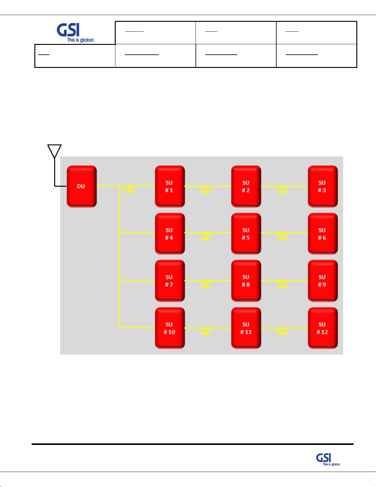
2.1. System Overview
PS-DAS is designed to improve coverage and capacity of Public Safety networks. Receiving signal via antenna, it
provides coverage Building in RF shadow.
© 2018 GS Instech Co., Ltd. All rights reserved.
Figure 3. PS-DAS Application Configurations
12
Page 13
Version
1.0
Date
NOV. 27, 2018
Page
13/ 42
Title
USER MANUAL
Prepared by
KO. SUNGMOO
Reviewed by
Approved by
2.2. Main Features
● All-in One Donor Unit
- Compose several units such as Optic Transceiver, NMS, PSU, BDA, Cavity Filter etc.
- Convenient to install in Middle Size Building with proper cost of one set
● Support the Antenna Feeding Solution
- Receiving signal via Antenna
● Choose the Filtering Methods accord to the operating condition
- For Neutral Host installations, able to support the Full Band Filtering
● Improving Service Quality under Multi-Carriers Area
- Up to 6 Non-Contiguous block and gain per block based on Downlink Input Topologies
- Dealing with Near-far & Uplink Noise Floor Rise
● Topologies
- 1:4 Branches between DU and SU.
- 3 Daisy Chain is possible by Internal Optic Daisy Chain Circuit.
- One DU can accommodate a total of 12 SU.
● Supporting Technologies
- LTE, P25
● Supporting Frequencies
- Public Safety Dual band (700M, 800M)
● Supporting Output Power
- Composite 5W with PSD-DAS-LI33 (2W per Band)
- Composite 2W with PSD-DAS-LI37 (5W per Band)
● Functions
- Support AGC, ALC, , ASD
● FCC Part 22, 24,27,90 & Part 15B class A / Class B
© 2018 GS Instech Co., Ltd. All rights reserved.
13
Page 14
Version
1.0
Date
NOV. 27, 2018
Page
14/ 42
Title
USER MANUAL
Prepared by
KO. SUNGMOO
Reviewed by
Approved by
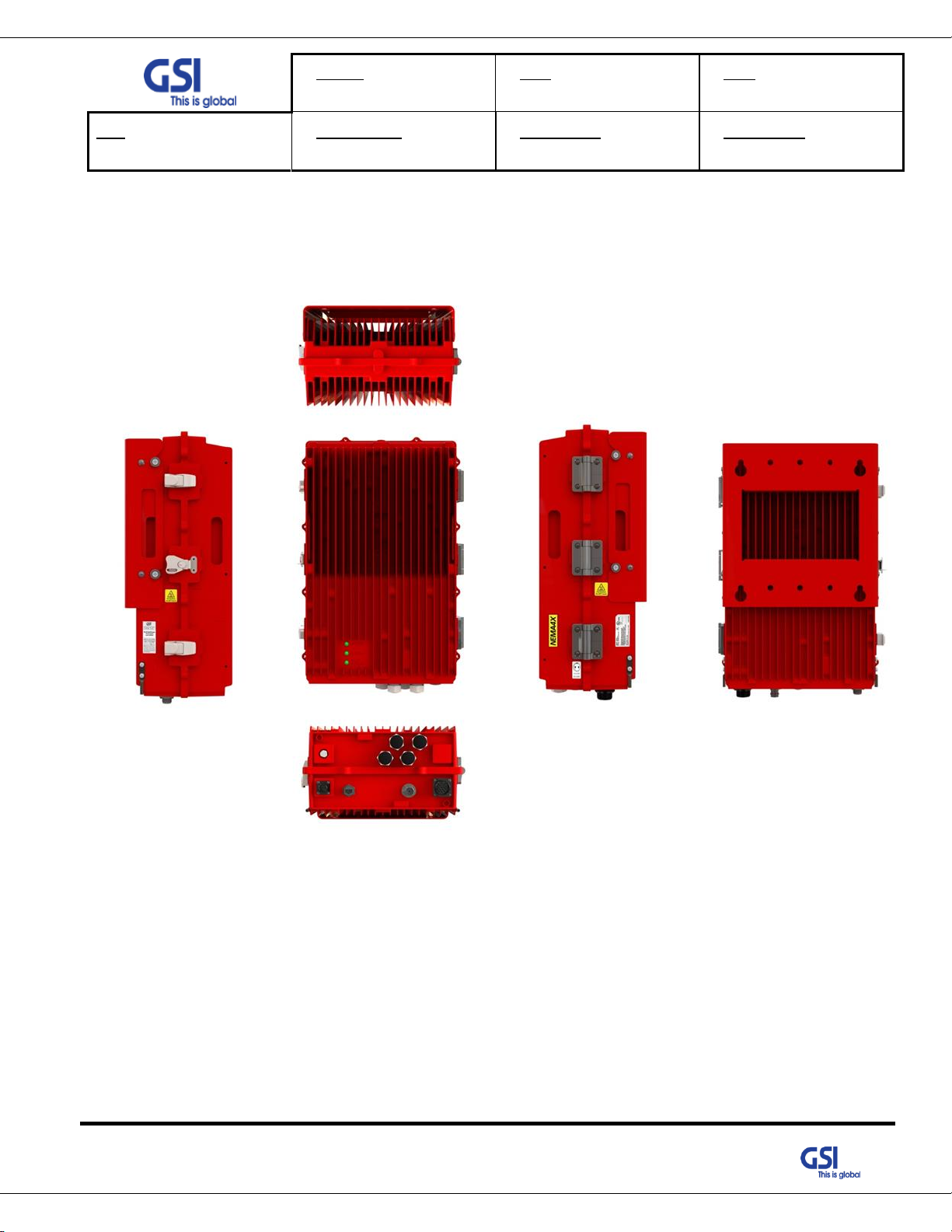
3. System Design for PSD-LI27 (Donor Unit)
3.1. Exterior View
© 2018 GS Instech Co., Ltd. All rights reserved.
Figure 4. PSD-LI27 Exterior View
14
Page 15

Version
1.0
Date
NOV. 27, 2018
Page
15/ 42
Title
USER MANUAL
Prepared by
KO. SUNGMOO
Reviewed by
Approved by
No
Name
Remark
1
DFU
700/800 Digital Filter Unit
2
RFU
700/800 RF Unit
3
PSU
In : DC +48V / Out : DC +28V
4
Cavity Filter
Duplexer for 700/800M
5
DOU1
Donor Optic Unit (2Port)
3.2. Interior View
© 2018 GS Instech Co., Ltd. All rights reserved.
Figure 5. PSD-LI27 Interior View
15
Page 16

Version
1.0
Date
NOV. 27, 2018
Page
16/ 42
Title
USER MANUAL
Prepared by
KO. SUNGMOO
Reviewed by
Approved by
6
DOU2
Donor Optic Unit (2Port)
7
I/O B’rd
Control and communication between each internal module, connection with
upper level management system
8
External Condenser
Using for Dying GASP
9
Optic Connector
Link Between the DOU and Optic Fiber Cable
10
Optic Fiber Reel
After connecting the cable, spool the long extra cable
11
LED B’rd
Displays the operating status and alarm status of the system
Table 1. PSD-LI27 Unit Configuration
© 2018 GS Instech Co., Ltd. All rights reserved.
16
Page 17

Version
1.0
Date
NOV. 27, 2018
Page
17/ 42
Title
USER MANUAL
Prepared by
KO. SUNGMOO
Reviewed by
Approved by
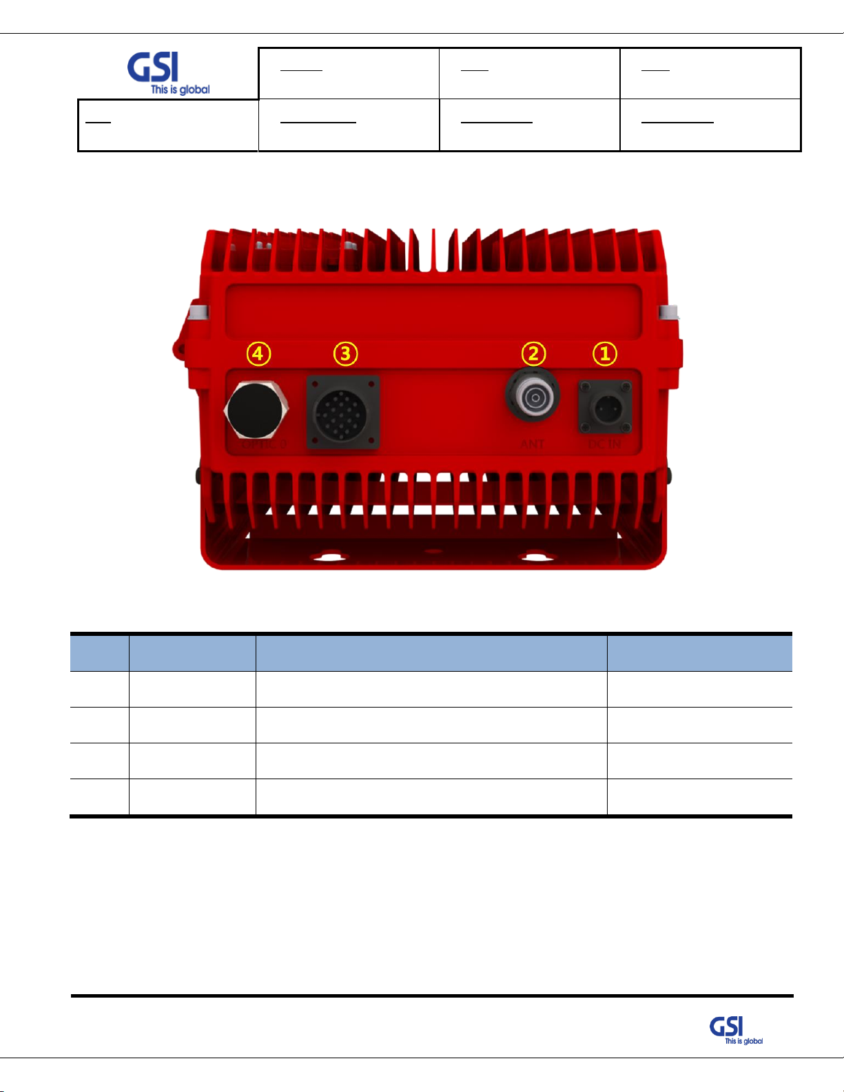
No
NAMES
DESCRIPTION
SPECIFICATION
1
DC IN
DC Input Outlet
MS3102A 14S-9P
2
LAN
Communicate a data between DU and Server
RJ-45 Waterproof
3
ANT
Feeding Downlink Signal / Transmit Uplink Output
4.3-10 Mini Din Connector
4
External Alarm
Send the alarm status to the External alarm Panel
MS3102A 22-14P
5
Optic
Link Between DU and SU
Metal Cable Gland
6
Vent-Core
Maintain Humidity & Temp Inside
IP66
3.3. External Interface
Figure 6. PSD-LI27 External Interface
© 2018 GS Instech Co., Ltd. All rights reserved.
Table 2. PSD-LI27 External Interface Description
17
Page 18

Version
1.0
Date
NOV. 27, 2018
Page
18/ 42
Title
USER MANUAL
Prepared by
KO. SUNGMOO
Reviewed by
Approved by
4. System Design for PSS-LI33 (Service Unit)
4.1. Exterior View
© 2018 GS Instech Co., Ltd. All rights reserved.
Figure 7. PSS-LI33 Exterior View
18
Page 19

Version
1.0
Date
NOV. 27, 2018
Page
19/ 42
Title
USER MANUAL
Prepared by
KO. SUNGMOO
Reviewed by
Approved by
No
Name
Remark
1
Cavity Filter
Duplexer for 700M & 800M
2
DL 800 HPA
1900MHz RF Power Amp Unit
3
DL 700 HPA
700MHz RF Power Amp Unit
4
PSU
DC Input Voltage: 48VDC / DC Output Voltage: +28V
5
SOU
Service Optic Unit
6
External Condenser
Using for Dying GASP
7
NMS Board
Apply for GUI/ Communicate with Donor Unit
8
Optic Connector
4Way RF Channel Distribute Unit
4.2. Interior View
Figure 8. PSS-LI33 Interior View
Table 3. PSS- LI33 Unit Configuration
© 2018 GS Instech Co., Ltd. All rights reserved.
19
Page 20
Version
1.0
Date
NOV. 27, 2018
Page
20/ 42
Title
USER MANUAL
Prepared by
KO. SUNGMOO
Reviewed by
Approved by
No
NAMES
DESCRIPTION
SPECIFICATION
1
DC IN
DC Input Outlet
MS3102A 14S-9P
2
ANT
Feeding Uplink Signal / Transmit Downlink Output
4.3-10 Din Connector
3
External Alarm
External Alarm Panel connect
MS3102A 22-14P
4
OPTIC 0
Insert the optic cable to Donor Unit
Metal Cable Gland
4.3. External Interface
Figure 9.PSS-LI33 External Interface
Table 4. PSS-LI37 External Interface Description
© 2018 GS Instech Co., Ltd. All rights reserved.
20
Page 21

Version
1.0
Date
NOV. 27, 2018
Page
21/ 42
Title
USER MANUAL
Prepared by
KO. SUNGMOO
Reviewed by
Approved by
5. System Design for PSS-LI37 (Service Unit)
5.1. Exterior View
© 2018 GS Instech Co., Ltd. All rights reserved.
Figure 10. PSS-LI37 Exterior View
21
Page 22

Version
1.0
Date
NOV. 27, 2018
Page
22/ 42
Title
USER MANUAL
Prepared by
KO. SUNGMOO
Reviewed by
Approved by
No
Name
Remark
1
Cavity Filter
Duplexer for 700M & 800M
2
DL 800 HPA
1900MHz RF Power Amp Unit
3
DL 700 HPA
700MHz RF Power Amp Unit
4
SOU
Service Optic Unit
5
PSU
DC Input Voltage: 48VDC / DC Output Voltage: +28V
6
NMS Board
Apply for GUI/ Communicate with Donor Unit
7
External Condenser
Using for Dying GASP
8
Optic Connector
4Way RF Channel Distribute Unit
5.2. Interior View
Figure 11. PSS-LI37 Interior View
Table 5. PSS- LI37 Unit Configuration
© 2018 GS Instech Co., Ltd. All rights reserved.
22
Page 23

Version
1.0
Date
NOV. 27, 2018
Page
23/ 42
Title
USER MANUAL
Prepared by
KO. SUNGMOO
Reviewed by
Approved by
No
NAMES
DESCRIPTION
SPECIFICATION
1
DC IN
DC Input Outlet
MS3102A 14S-9P
2
External Alarm
External Alarm Panel connect
MS3102A 22-14P
3
Vent-Core
Maintain Humidity & Temp Inside
IP66
4
ANT
Feeding Uplink Signal / Transmit Downlink Output
4.3-10 Din Connector
5
OPTIC 0 / 1
Insert the optic cable to Donor Unit
Metal Cable Gland
5.3. External Interface
Figure 12. PSS-LI37 External Interface
© 2018 GS Instech Co., Ltd. All rights reserved.
Table 6. PSS-LI37 External Interface Description
23
Page 24

Version
1.0
Date
NOV. 27, 2018
Page
24/ 42
Title
USER MANUAL
Prepared by
KO. SUNGMOO
Reviewed by
Approved by
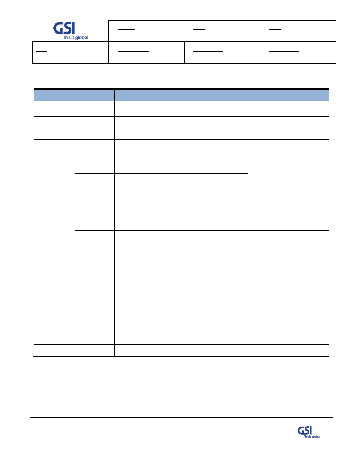
Parameter
Down Link
Up Link
Remark
Frequency Range
758MHz~768MHz
788MHz~798MHz
LTE
769MHz~775MHz
799MHz~805MHz
P25
806MHz~816MHz
P25
Input Range
-62dBm ~ -17dBm/ Total
-62dBm
Per Band
Output Power
+33dBm with PSS-LI33
+27dBm(0.5W)
With PSD-LI27
2W
+37dBm with PSS-LI37
5W
Gain
Range
50dB ~ 95dB
44dB ~ 89dB
PSS-LI33
54dB ~ 99dB
PSS-LI37
Adjust Step
1dB
1dB
Accuracy
±1dB
±1dB
Channel Capacity
【P25】 6.25 / 12.5 / 25 / 50 / 75 KHz
Class A
【LTE】 5M, 10M
Class B
【P25】 100 / 125 / 150 / 175 / 200 / 225 / 250 KHz
Ripple
3dB p-p
Roll off
> 50dBc @ Channel OBW ±1MHz
EVM
< 8% for 67QAM
< 5% for 16QAM
For LTE
Frequency Error
< 0.05ppm
System Delay
< 220us
Exclude Fiber
Optic Delay
Noise Figure
Less than 6dB @ Min & Max Gain
Only UL
VSWR
< 1.5 : 1
OB Unwanted
Emission
<-5.5dBm @50KHz ≤ ∆f < 5.05MHz (RBW: 100KHz)
For LTE
<-12.5dBm @5.05MHz ≤ ∆f < 10.05MHz (RBW: 100KHz)
<-13dBm @10.5MHz ≤ ∆f < 15MHz (RBW: 1MHz)
ACLR
> 45dBc @ ±5MHz, ±10MHz, ±20MHz, ±40MHz
For LTE
6. System Specification
6.1. RF Performance
851MHz~861MHz
© 2018 GS Instech Co., Ltd. All rights reserved.
Table 7. PS-DAS RF Performance Description
24
Page 25

Version
1.0
Date
NOV. 27, 2018
Page
25/ 42
Title
USER MANUAL
Prepared by
KO. SUNGMOO
Reviewed by
Approved by
No
NAMES
DESCRIPTION
SPECIFICATION
DL
700 (PSBB)
758MHz ~ 768MHz
LTE
700 (PSNB)
769MHz ~ 775MHz
P25
800 (PSNB)
851MHz ~ 861MHz
P25
UL
700 (PSBB)
788MHz ~ 798MHz
LTE
700 (PSNB)
799MHz ~ 805MHz
P25
800 (PSNB)
806MHz ~ 816MHz
P25
[MHz]
Service
Donor Antenna
RFU
DFM
HPA
Remarks
Start
Stop
Start
Stop
Start
Stop
Start
Stop
DL 700
758
775
758
775
758
775
758
775
DL 800
851
861
851
861
851
861
851
861
UL
788
816
788
816
788
816
788
816
6.2. Frequency Information
6.2.1. Frequency Information
Table 8. PS-DAS Frequency Allocation
6.2.2. Block Diagram
Figure 13. System Block Diagram
Table 9. PS-DAS Module Frequency Information
© 2018 GS Instech Co., Ltd. All rights reserved.
25
Page 26
Version
1.0
Date
NOV. 27, 2018
Page
26/ 42
Title
USER MANUAL
Prepared by
KO. SUNGMOO
Reviewed by
Approved by
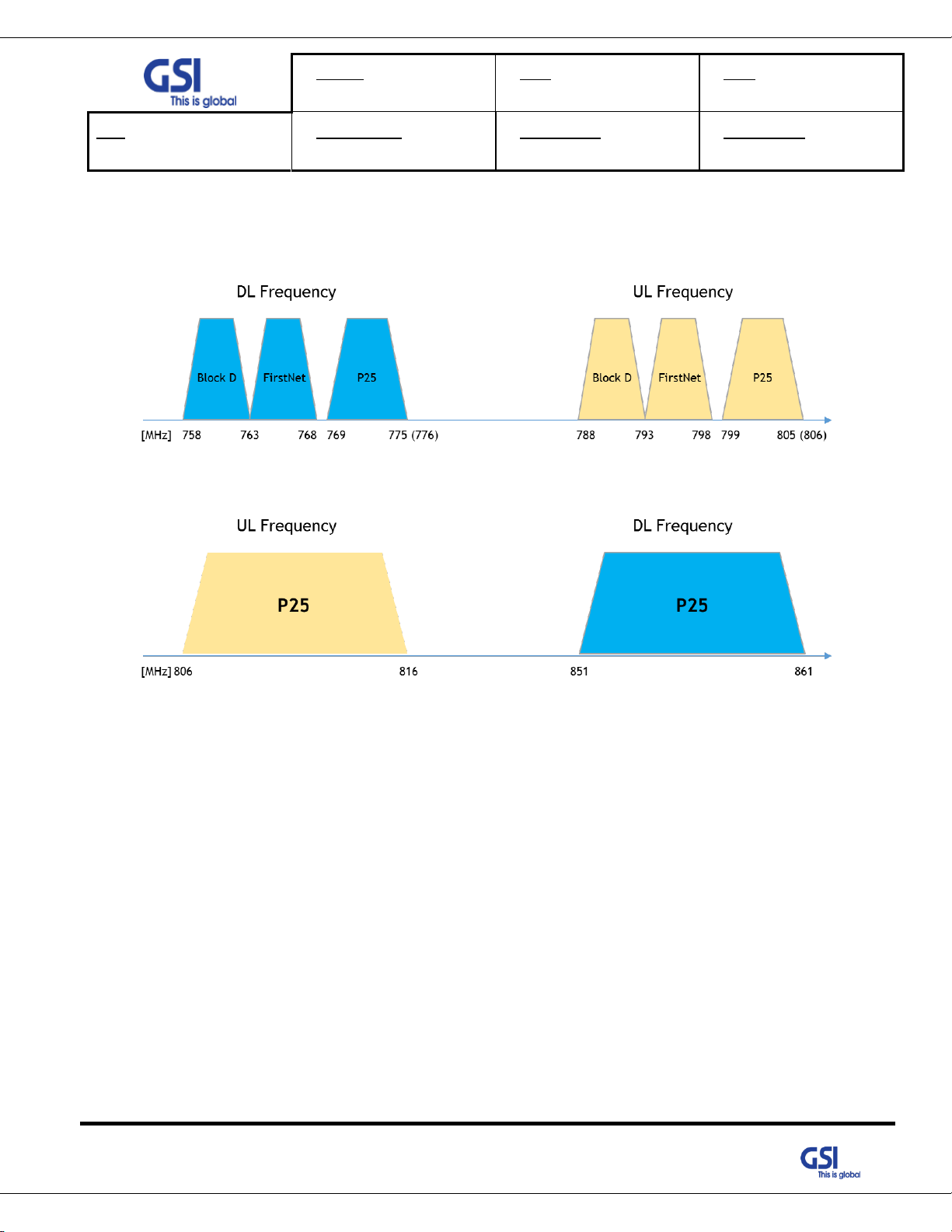
6.2.3. Service Plan
1) The LTE network integrates Upper D band and FirstNet to have max. 10MHz Service BW.
2) The P25 Network has a Guard Band of 768-769MHz and 775-776MHz.
Figure 14. 700MHz Band Allocation
Figure 15. 800MHz Band Allocation
© 2018 GS Instech Co., Ltd. All rights reserved.
26
Page 27
Version
1.0
Date
NOV. 27, 2018
Page
27/ 42
Title
USER MANUAL
Prepared by
KO. SUNGMOO
Reviewed by
Approved by
Parameter
Specification
Remark
Donor/ Service
Antenna Filter
DUPLEXER+BAND COMBINER
One port In/Output
Power Supply
DC Input Voltage: 48VDC
Operation Temperature
-40°C~+60°C (5~95%RH)
Storage Temperature
-40°C~+80°C (5~95%RH)
Connectors
Antenna
4.3-10 Mini DIN Female
Power
MS-3106A 14S-9P
Ext. Alarm
MS3102A 22-14P
Optic
SC/APC
Cable
1/2" Plenum-Rated Air-Dielectric Coaxial Cable
Size
PSD-LI27
13.8 x 21.7 x 7.9
Inches
PSS-LI33
11.2 x 15.2 x 6.9
Inches
PSS-LI37
13.2 x 18.9 x 6.4
Inches
Weigh
PSD-LI27
56.2
Lbs.
PSS-LI33
31.5
Lbs.
PSS-LI37
40.3
Lbs.
Power
Consumption
PSD-LI27
106
W
PSS-LI33
92
W
PSS-LI37
140
W
Environment
IP66
MTBF
100,000 hours or higher
Grounding
nonferrous metal and anchoring point on bottom
For RF and power cabling
Mount Application
Wall Mount
6.3. Configuration & Mechanical Specification
Table 10. PS-DAS Configuration & Mechanical Specification
© 2018 GS Instech Co., Ltd. All rights reserved.
27
Page 28

Version
1.0
Date
NOV. 27, 2018
Page
28/ 42
Title
USER MANUAL
Prepared by
KO. SUNGMOO
Reviewed by
Approved by
Alarm No.
Alarm Name
Pin No.
Relay Name
Cable Color
Remarks
Alarm1
User Defined
1
NC1
Black
2 COM1
Brown
3 NO1
Red
Alarm2
User Defined
4
NC2
Orange
5
COM2
Yellow
6
NO2
Green
Alarm3
User Defined
7
NC3
Blue
8 COM3
Violet
9 NO3
Gray
Alarm4
User Defined
10
NC4
White
11
COM4
Black & White Dotted line
12
NO4
Brown & Black Dotted line
External Alarm
Input. #1
User Defined
13
NC5
Red & Black Dotted line
14
COM5
Orange & Black Dotted line
15
NO5
Yellow & Black Dotted line
External Alarm
Input. #2
User Defined
16
NC6
Green & Black Dotted line
17
COM6
Blue& Black Dotted line
18
NO6
Violet & Black Dotted line
6.4. External Alarm Connect
● If system alarm occurs, Alarm information transfer to the alarm panel that is hardwired through the EXT
ALARM port.
● The system supports Dry Contact Form C.
● The System can send a total of 4 alarms to the Alarm Panel according to user defined.
● Also, according to the User environment, the system can input two external alarms and transmit them to
the alarm panel.
© 2018 GS Instech Co., Ltd. All rights reserved.
28
Page 29

Version
1.0
Date
NOV. 27, 2018
Page
29/ 42
Title
USER MANUAL
Prepared by
KO. SUNGMOO
Reviewed by
Approved by
7. System Block Configuration
7.1. Block Diagram
Figure 16. PSD-LI27 Block Diagram Configuration
The repeater improves service in the Dual Band Public safety networks.
User may select frequency band according to the site peculiarities.
After receiving a weak signal from Donor antenna, the PSD-LI27 sends downlink signal to PSS-LI33/37 using DOU.
DOU supports the translation of RF signal to Optic signal for connecting PSS-LI37 through the fiber optic cable. And
then Uplink Signal that received from PSS-LI37 amplify, is send to the Base station via Donor Antenna.
© 2018 GS Instech Co., Ltd. All rights reserved.
Figure 17. PSS-LI33 / 37 Block Diagram Configuration
29
Page 30

Version
1.0
Date
NOV. 27, 2018
Page
30/ 42
Title
USER MANUAL
Prepared by
KO. SUNGMOO
Reviewed by
Approved by
PSS-LI33/37 is operating very similar to the PSD-LI27
After receiving an Uplink Signal from service antenna, the PS-DASD-LI33/37 sends Uplink signal to PSD-LI27 using
SOU (Service Optic Unit).
SOU supports the translation of RF signal to Optic signal for connecting PSD-LI27 through the fiber optic cable. And
then Down Signal that received from PSD-LI27 amplify, is send to the Mobile station via Service Antenna.
© 2018 GS Instech Co., Ltd. All rights reserved.
30
Page 31

Version
1.0
Date
NOV. 27, 2018
Page
31/ 42
Title
USER MANUAL
Prepared by
KO. SUNGMOO
Reviewed by
Approved by
1. Go to Local Connection
2. Click on "Properties"
3. Highlight "Internet Protocol"
4. Click on "Properties"
5. Choose "Obtain DNS Server
address automatically"
6. Clink OK
8. GUI Overview
• Provide all functions that can be performed at Service Unit will be available thru the Donor Unit.
• Support the GUI pages that will be addressable via UDP Interface.
8.1. Configuration the Laptop to Connect to the Repeater
• Connect an Ethernet crossover cable from the LAN port of the repeater’s bottom side to your laptop
© 2018 GS Instech Co., Ltd. All rights reserved.
31
Page 32

Version
1.0
Date
NOV. 27, 2018
Page
32/ 42
Title
USER MANUAL
Prepared by
KO. SUNGMOO
Reviewed by
Approved by
8.2. Login-In Screen
• GUI Screen for Log-In
• Enter the IP Address ① "192.168.2.1" and Port into GUI Main Screen. And then ② Connect.
• If the window at the top of the screen ③blinks green, you can verify that the connection has completed successfully.
• The laptop connected to the System, you can check ⑤ Topology tree of the PS-DAS by pressing the System button on the
screen.
• Click the location of the device you wish to access in the tree on the screen and click ⑦ Open button, user has moving to
the target device.
© 2018 GS Instech Co., Ltd. All rights reserved.
32
Page 33

Version
1.0
Date
NOV. 27, 2018
Page
33/ 42
Title
USER MANUAL
Prepared by
KO. SUNGMOO
Reviewed by
Approved by
8.3. RF Status
• GUI Screen for display Repeater’s RF Status
© 2018 GS Instech Co., Ltd. All rights reserved.
33
Page 34

Version
1.0
Date
NOV. 27, 2018
Page
34/ 42
Title
USER MANUAL
Prepared by
KO. SUNGMOO
Reviewed by
Approved by
8.4. SU Configuration
• GUI Screen in order to change the RF values
• User may change the various RF values of the repeater on this page
• Changes will not take effect until you click "Apply" button
• This menu is where the installer will choose references for specific implementation
• ① in the GUI screen shows SOU behavior, PD / LD Power Level detection, and SOU related alarms.
• ② in the GUI screens involve the operation of DL 700 / 800 HPA. Display On / Off control , status and Alarm information of
HPA.
© 2018 GS Instech Co., Ltd. All rights reserved.
34
Page 35
Version
1.0
Date
NOV. 27, 2018
Page
35/ 42
Title
USER MANUAL
Prepared by
KO. SUNGMOO
Reviewed by
Approved by
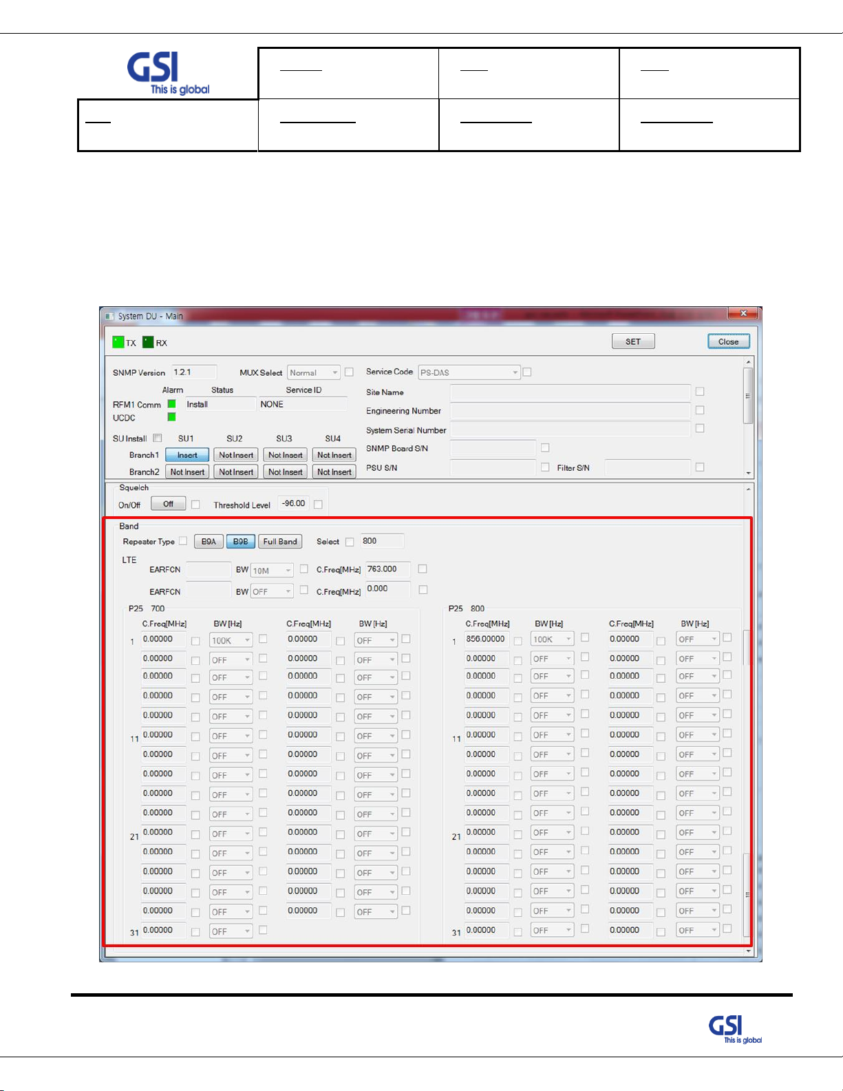
8.5. Band Selection
• Repeater support the capacity of P25 and LTE Technologies
• For P25, 32 non-contiguous bands can be used
• Support the LTE 5MHz, 10MHz
• User can set the desired channel using the GUI
© 2018 GS Instech Co., Ltd. All rights reserved.
35
Page 36
Version
1.0
Date
NOV. 27, 2018
Page
36/ 42
Title
USER MANUAL
Prepared by
KO. SUNGMOO
Reviewed by
Approved by
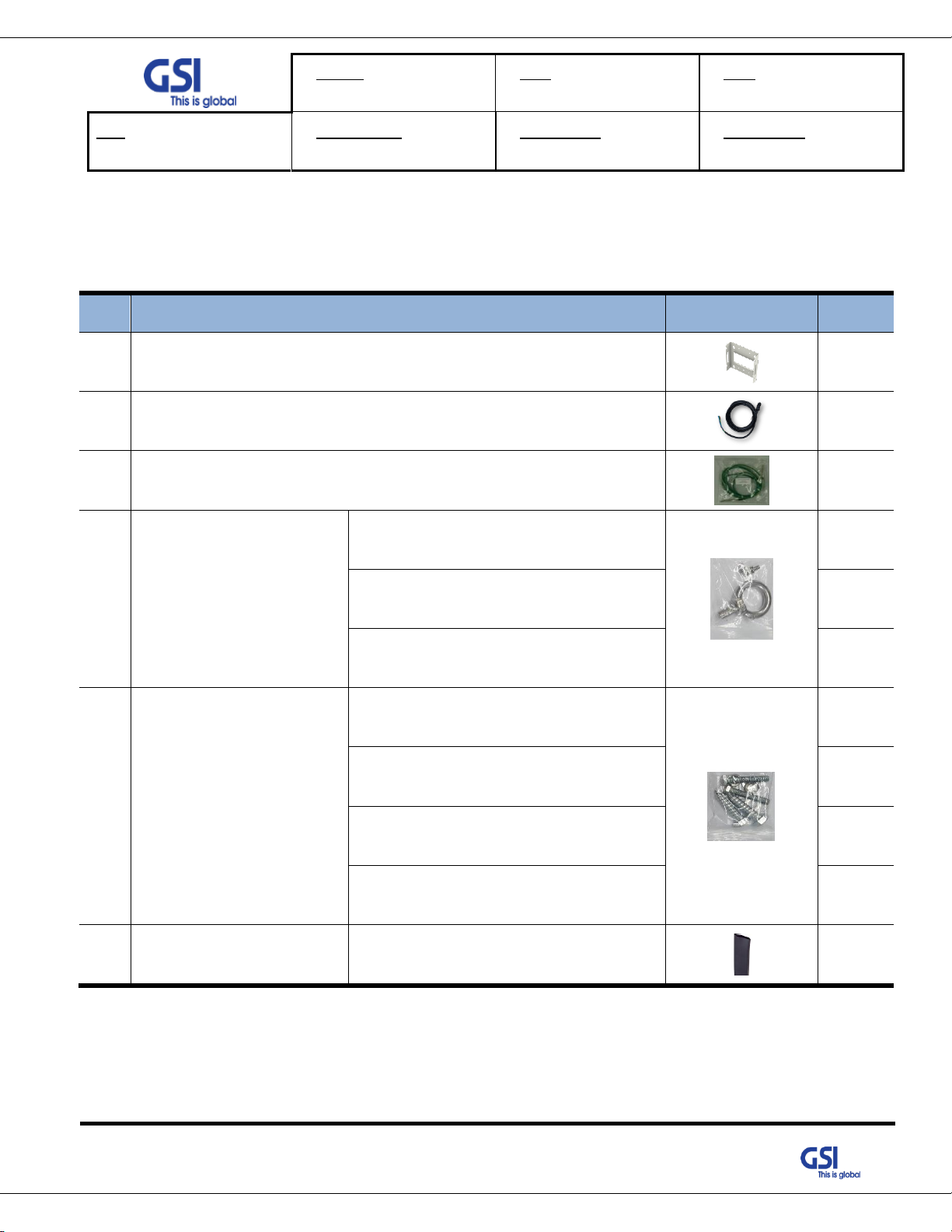
#
Contents
Picture
Q’ty
1
Mounting Bracket
1EA
2
AC Power Cable SJT 3/16 AWG, 6ft
1EA
3
Frame Ground Cable with Tubular Cable Lug, 6ft
1EA
4
Installation purchase set
EYE BOLT(M12)
1EA
M5x12mm WRENCH BOLT, SEMS
2EA
PH(+) M4x8mm ,SEMS
4EA
5
Mounting Screw set
LAG SCREW 3/8”x3”
2EA
HEX HEAD 3/8”x2”, SCM440
2EA
Φ10.5mm/Φ21mm PLAIN WASHER
2EA
Φ10.2mm/Φ18.4mm SPRING WASHER
2EA
6
Tubing Tube Sleeve Black
Φ30mm/L:150mm Adhesive Polyolefin
3:1 Heat Shrink
1EA
9. System Installation
• This chapter describes how to install the repeater and Cabling method
• The needed accessories and tools are list up as below
© 2018 GS Instech Co., Ltd. All rights reserved.
Table 11. PS-DAS Installation Accessories
36
Page 37
Version
1.0
Date
NOV. 27, 2018
Page
37/ 42
Title
USER MANUAL
Prepared by
KO. SUNGMOO
Reviewed by
Approved by
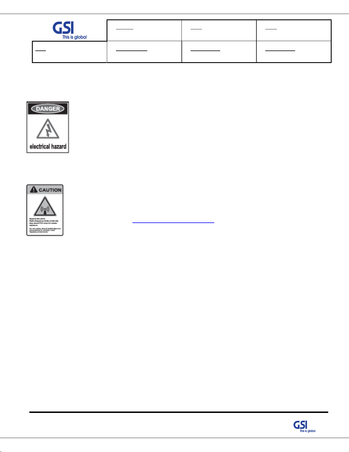
9.1. Warnings and Hazards
9.1.1. Electric Shock
• Opening the Repeater could result in electrical shock and may cause severe
injury
• Operating the Repeater with antennas in very close proximity facing each other
could lead to severe damage to the repeater
9.1.2. Exposure to RF
Working with the repeater while in operation, may expose the technician to
RF electromagnetic fields that exceed FCC Rules for human expose.
Visit the FCC Website at http://www.fcc.gov/oet/rfsafety to learn more about
The effects of exposure to RF electromagnetic fields
© 2018 GS Instech Co., Ltd. All rights reserved.
37
Page 38

Version
1.0
Date
NOV. 27, 2018
Page
38/ 42
Title
USER MANUAL
Prepared by
KO. SUNGMOO
Reviewed by
Approved by
Protection gloves and goggles
Make sure that worker wears protection gloves and goggles to prevent damages from
debris while drilling holes in a Pole or Wall
Cautions while drilling on the pole
Drilling thru-hole on a center of the pole
9.2. Service Man Installation Guide
9.2.1. PSS-LI37 Fixing the Wall Mount Type
The procedure for fixing the pole type system is as follows.
1) To mount the system on the wall, first fix the bracket on the wanted position.
2) Hang the system to the hooking position at the top of the mounting bracket
3) Push the system to the hooking position at the bottom of the mounting bracket.
Figure 18. The way to fix firmly the System for Pole Mounting
38
© 2018 GS Instech Co., Ltd. All rights reserved.
Page 39

Version
1.0
Date
NOV. 27, 2018
Page
39/ 42
Title
USER MANUAL
Prepared by
KO. SUNGMOO
Reviewed by
Approved by
4) Align the system with the fixing holes of the mounting bracket and fix them firmly
9.2.2. PSD-LI27 / PSS-LI33 Fixing the Wall Mount Type
39
© 2018 GS Instech Co., Ltd. All rights reserved.
Page 40

Version
1.0
Date
NOV. 27, 2018
Page
40/ 42
Title
USER MANUAL
Prepared by
KO. SUNGMOO
Reviewed by
Approved by
Cautions System leveling
Before fixing the system, Check the horizontal and vertical level using a spirit level
Figure 19.The way to fix firmly the System for Wall Mounting
40
© 2018 GS Instech Co., Ltd. All rights reserved.
Page 41

Version
1.0
Date
NOV. 27, 2018
Page
41/ 42
Title
USER MANUAL
Prepared by
KO. SUNGMOO
Reviewed by
Approved by
Port Outlook
(System Side)
Port numbering
for MS
NAME
Description
A
DC (+)
+48V
B
GND
GND
9.3. Cable Connection
9.3.1. DC Power cable connection
• Repeater supports a free DC Input voltage 48V
• Provided Power cable is single type, so it can be used flexibly
• The pin description of DC Port is below. User should connect exact polarity of DC
• The specification & Connection of DC Power Cable
- DC Connector: CAR3102A-14S-9S
- Connect Port A for inserting DC Power
9.3.2. Local Maintenance Connection
• Repeater Support a RJ-45 connector
9.3.3.
© 2018 GS Instech Co., Ltd. All rights reserved.
41
Page 42
Version
1.0
Date
NOV. 27, 2018
Page
42/ 42
Title
USER MANUAL
Prepared by
KO. SUNGMOO
Reviewed by
Approved by
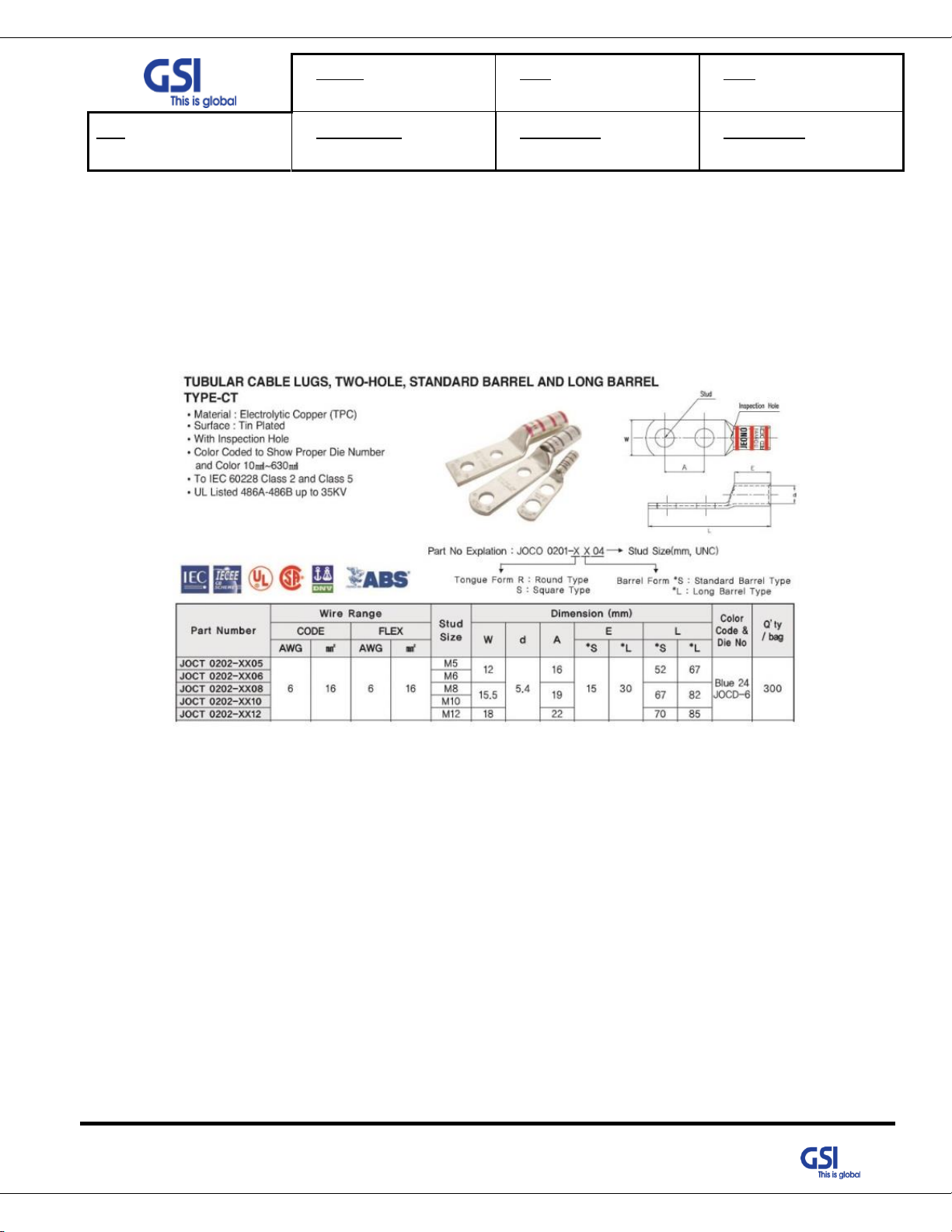
Frame Ground
9.3.4. Grounding cable Connection
• Frame(Earth) Wire size is AWG #6. The way to install the grounding cable is below
• The specification of ground terminal lug is like below (Refer to JOCT 0202-RL05)
42
© 2018 GS Instech Co., Ltd. All rights reserved.
 Loading...