

Page 1
Version
1.1
Date
January 28th, 2019
Page
1/ 47
Title
USER MANUAL
Prepared by
Reviewed by
Approved by
© 2019 GS Teletech Inc. All rights reserved
1
GST-IC-ELITE-TNR
(outdoor)
USER MANUAL
GS Teletech Inc.
Page 2
Version
1.1
Date
January 28th, 2019
Page
2/ 47
Title
USER MANUAL
Prepared by
Reviewed by
Approved by
© 2019 GS Teletech Inc. All rights reserved
2
DATE
NAMES
DESCRIPTIONS
VERSION
REMARK
January 10th, 2019
Y.J.KIM
Original Draft
1.0
January 28th, 2019
Y.J.KIM
Changed the only outdoor type
1.1
[CHANGE RECORD]
Page 3
Version
1.1
Date
January 28th, 2019
Page
3/ 47
Title
USER MANUAL
Prepared by
Reviewed by
Approved by
© 2019 GS Teletech Inc. All rights reserved
3
CHAPTER’s INDEX
[TABLE OF CONTENTS]
1. GENERAL ......................................................................................................................................... 7
1.1. Purpose ......................................................................................................................................................................... 7
1.2. Copyright ...................................................................................................................................................................... 7
2. INTRODUCTION ............................................................................................................................. 8
2.1. System Overview ........................................................................................................................................................ 8
2.2. Main Features .............................................................................................................................................................. 9
3. SYSTEM DESIGN .......................................................................................................................... 10
3.1. Perspective View ....................................................................................................................................................... 10
3.2. Exterior View ............................................................................................................................................................. 11
3.3. Interior View (Outdoor) ........................................................................................................................................... 12
3.4. External Interface (Indoor & Outdoor) ................................................................................................................. 13
4. SYSTEM SPECIFICATION ............................................................................................................. 14
4.1. RF Performance ......................................................................................................................................................... 14
4.2. ICS General Performance ........................................................................................................................................ 15
4.3. CH Capacity Information ......................................................................................................................................... 15
4.3.1. LTE Band 41 ........................................................................................................................................................................................... 15
4.3.2. NR Band N41 ........................................................................................................................................................................................ 16
4.5. Configuration & Mechanical Specification ......................................................................................................... 17
5. SYSTEM BLOCK CONFIGURATION ........................................................................................... 18
5.1. RF Signal Flow (Outdoor) ........................................................................................................................................ 18
5.2. Data Signal Flow ....................................................................................................................................................... 19
5.3. Power Supply Flow ................................................................................................................................................... 20
Page 4

Version
1.1
Date
January 28th, 2019
Page
4/ 47
Title
USER MANUAL
Prepared by
Reviewed by
Approved by
© 2019 GS Teletech Inc. All rights reserved
4
6. STATUS/ CONTROL & ALARM MONITORING ....................................................................... 21
6.1. Status Monitoring and Control Parameters ....................................................................................................... 21
6.2. Alarm Monitoring ..................................................................................................................................................... 22
7. WEB-UI OVERVIEW ..................................................................................................................... 24
7.1. Configuration the Laptop to Connect to the Repeater ..................................................................................... 24
7.2. Login-In Screen.......................................................................................................................................................... 25
7.3. RF Status & Control .................................................................................................................................................. 26
7.4. Alarm Configuration ................................................................................................................................................ 27
7.5. Communication Configuration ............................................................................................................................... 28
7.6. User Management .................................................................................................................................................... 29
7.7. Alarm Log................................................................................................................................................................... 30
7.8. Log ............................................................................................................................................................................... 31
7.9. Troubleshooting ........................................................................................................................................................ 32
7.10. Software Update ....................................................................................................................................................... 33
7.11. System Reset ............................................................................................................................................................. 34
7.12. Factory Default Setting ........................................................................................................................................... 35
7.13. Configuration Transfer ............................................................................................................................................. 36
8. SYSTEM INSTALLATION.............................................................................................................. 37
8.1. Warnings and Hazards ............................................................................................................................................. 38
8.1.1. Electric Shock ........................................................................................................................................................................................ 38
8.1.2. Exposure to RF ..................................................................................................................................................................................... 38
8.2. Cabling ........................................................................................................................................................................ 39
8.3. Installation Guide for Crew ................................................................................................................................... 41
8.3.1. Wall Mount Installation .................................................................................................................................................................... 41
8.4. Cable Connection...................................................................................................................................................... 44
8.4.1. AC Power cable connection ........................................................................................................................................................... 44
8.4.2. FAN Power Cable Connection (OPTION) ................................................................................................................................. 44
8.4.3. RET Cable Connection (Option) ................................................................................................................................................... 45
8.4.4. Local Maintenance Connection .................................................................................................................................................... 45
Page 5
Version
1.1
Date
January 28th, 2019
Page
5/ 47
Title
USER MANUAL
Prepared by
Reviewed by
Approved by
© 2019 GS Teletech Inc. All rights reserved
5
FIGURE’s INDEX
8.4.5. Grounding cable Connection ........................................................................................................................................................ 46
9. FCC WARNING STATEMENT ...................................................................................................... 47
Figure 1. GST-IC-ELITE-TNR Application Configurations ................................................................................................... 8
Figure 2. GST-IC-ELITE-TNR Perspective View ................................................................................................................. 10
Figure 3. GST-IC-ELITE-TNR Exterior View ....................................................................................................................... 11
Figure 5. GST-IC-ELITE-TNR Interior View(Outdoor) ....................................................................................................... 12
Figure 6. GST-IC-ELITE-TNR External Interface ............................................................................................................... 13
Figure 8. GST-IC-ELITE-TNR RF Signal Flow (Outdoor) .................................................................................................... 18
Figure 9. GST-IC-ELITE-TNR Signal and Data Flow ........................................................................................................... 19
Figure 10. GST-IC-ELITE-TNR Power Supply Flow ............................................................................................................ 20
Figure 19. Laptop Configuration for connecting the Web-UI ......................................................................................... 24
Figure 20. The way to Log-in on the Web Browser Screen ............................................................................................ 25
Figure 21. RF Status monitoring & Control ....................................................................................................................... 26
Figure 22. System Alarm Configurations ........................................................................................................................... 27
Figure 23. System Information for connecting configurations ...................................................................................... 28
Figure 24. System Information about User Management................................................................................................ 29
Figure 25. The way to check System Alarm Log .............................................................................................................. 30
Figure 26. The way to read a Log History ......................................................................................................................... 31
Figure 27. The information of Contact point in case of occurring Field Troubleshooting ........................................ 32
Figure 28. The way to reload new software using the Web-UI...................................................................................... 33
Figure 29. The way to reset the system using the Web-UI ............................................................................................ 34
Figure 30. The way to restore Factory Default Setting for repeater ........................................................................... 35
Figure 31. The way to down/ up load configuration between laptop and repeater .................................................. 36
Figure 37. GST-IC-ELITE-TNR-Outdoor Cabling Diagram ................................................................................................. 39
Figure 31. Mounting Bracket Shape ................................................................................................................................... 41
Figure 44. Fixing the Bracket for installing a Wall Mount .............................................................................................. 42
Figure 45. The way to hang the system for Wall Mounting ............................................................................................ 43
Figure 46. The way to fix firmly the System for Wall Mounting .................................................................................... 43
Figure 49. RJ-45 Interface for connecting the Local Maintenance .............................................................................. 45
Figure 50. The way to install the Frame Ground Cable and Lug specifications.......................................................... 46
Page 6
Version
1.1
Date
January 28th, 2019
Page
6/ 47
Title
USER MANUAL
Prepared by
Reviewed by
Approved by
© 2019 GS Teletech Inc. All rights reserved
6
TABLE’s INDEX
Table 2. GST-IC-ELITE-TNR Unit Configuration ................................................................................................................. 12
Table 3. GST-IC-ELITE-TNR External Interface Description ............................................................................................ 13
Table 4. GST-IC-ELITE-TNR RF Performance Description ................................................................................................ 14
Table 5. GST-IC-ELITE-TNR ICS General Performance ..................................................................................................... 15
Table 6. GST-IC-ELITE-TNR Operation Band for LTE Band 41 ......................................................................................... 16
Table 7. GST-IC-ELITE-TNR Operation Band for NR Band N41 ........................................................................................ 16
Table 8. GST-IC-ELITE-TNR Mechanical & Environment conditions ............................................................................... 17
Table 10. GST-IC-ELITE-TNR RF Signal Flow (Outdoor) ................................................................................................... 18
Table 11. GST-IC-ELITE-TNR Data Signal Flow .................................................................................................................. 19
Table 12. GST-IC-ELITE-TNR Power Supply Flow .............................................................................................................. 20
Table 13. GST-IC-ELITE-TNR Status Monitoring and Control Parameters ..................................................................... 22
Table 14. Monitoring Alarm Parameters ............................................................................................................................ 23
Table 13. GST-Ic-ELITE-TNR Installation Accessories ....................................................................................................... 37
Table 13. GST-IC-ELITE-TNR-Outdoor Connecting Cable ................................................................................................. 39
Table 14. AC Power Connector Configuration ................................................................................................................... 44
Table 15. GST-IC-ELIT TNR FAN Power Cable Connection ............................................................................................... 44
Table 16. GST-IC-ELIT TNR RET Cable Connection ........................................................................................................... 45
Page 7

Version
1.1
Date
January 28th, 2019
Page
7/ 47
Title
USER MANUAL
Prepared by
Reviewed by
Approved by
© 2019 GS Teletech Inc. All rights reserved
7
1. General
1.1. Purpose
This document introduces features, specifications, structures and operation guideline for the GST-
IC-ELITE-TNR LTE & NR
1.2. Copyright
All text and image in this document are subject to the copyright of GS Teletech Inc.
This document may not be reproduced, distributed, or modified without the written permission
of GS Teletech Inc.
Page 8
Version
1.1
Date
January 28th, 2019
Page
8/ 47
Title
USER MANUAL
Prepared by
Reviewed by
Approved by
© 2019 GS Teletech Inc. All rights reserved
8
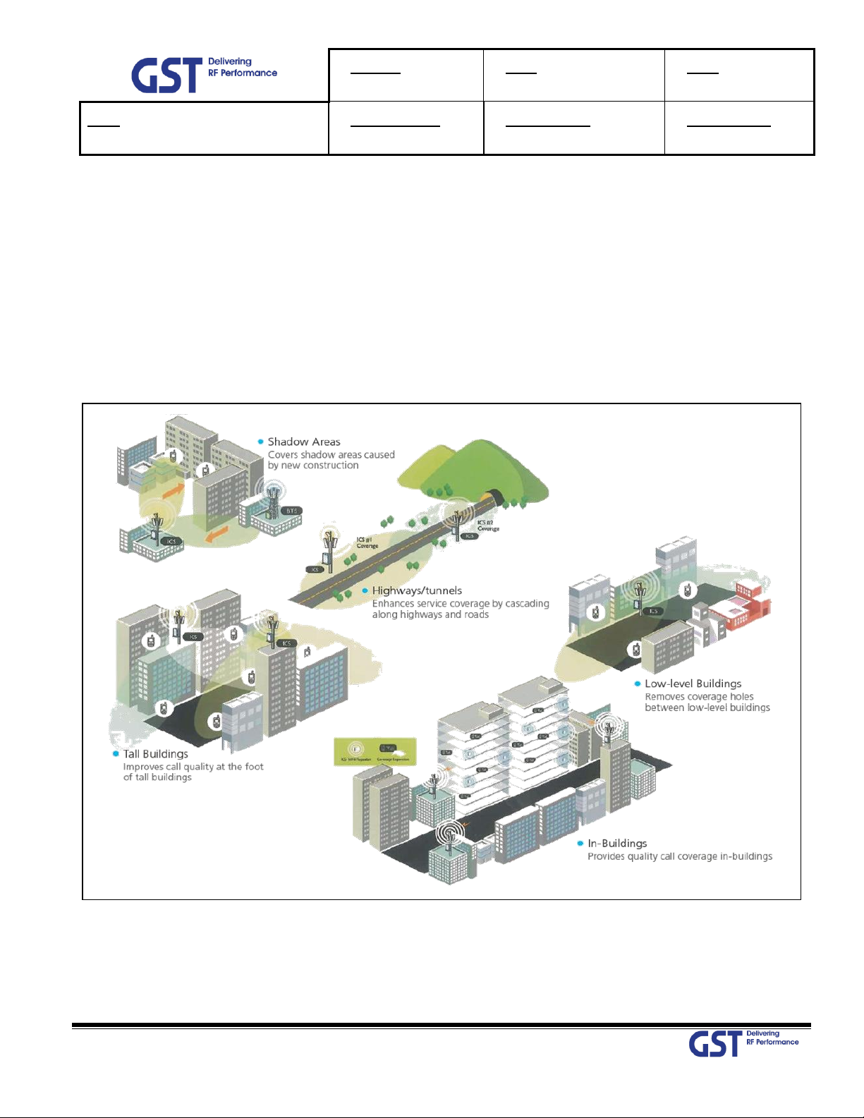
2. Introduction
2.1. System Overview
GST-IC-ELITE-TNR is designed to improve coverage and capacity of LTE Band 41 and NR Band N41 services in all
shadowed and blanked areas of Sprint network.
GST-IC-ELITE-TNR receives and improves weak signals as cancelling the multi-path interference even if there is a lack
of isolation between Donor and Service antenna.
This solution does not request any costs for Backhaul installation, so will save OPEX and CAPEX.
Figure 1. GST-IC-ELITE-TNR Application Configurations
Page 9

Version
1.1
Date
January 28th, 2019
Page
9/ 47
Title
USER MANUAL
Prepared by
Reviewed by
Approved by
© 2019 GS Teletech Inc. All rights reserved
9
2.2. Main Features
• Maintain the Quality of Demodulation performance on the Overlay-Cell Region using Delay-Reduction
Technology (Less than 4us for LTE & 2.41us for NR)
• Provide the SNMP Solution
• Ensure the Uplink-Sensitivity and Suppress Rising-UL noise floor under high out-power at Downlink using
PIMD-Reduction Technology
• Excellent RF Specifications
- High Gain: more than 95dB
- Low Noise figure under all system gain condition: Less than 5dB
- Grate Performance of Interference Cancellation: G=I+10dB
- High Rejection: More than -50dBc at Band Edge ± 1MHz for LTE BAND
More than 30dBc at Band Edge ± 1MHz For NR BAND
More than 50dBc at Band Edge ± 1.5MHz for NR BAND
• Adaptable functions for Operation
- RS (Pilot) Aware, Smart ALC & ASD, Attenuator for each Band
- Maximum 60MHz (20MHz *3carrier) for LTE and 60MHz for NR
• Complies with NEMA 4 (equal to IP66) for indoor & Outdoor application
• Apply for Cascade 6 chain installation
Page 10
Version
1.1
Date
January 28th, 2019
Page
10/ 47
Title
USER MANUAL
Prepared by
Reviewed by
Approved by
© 2019 GS Teletech Inc. All rights reserved
10
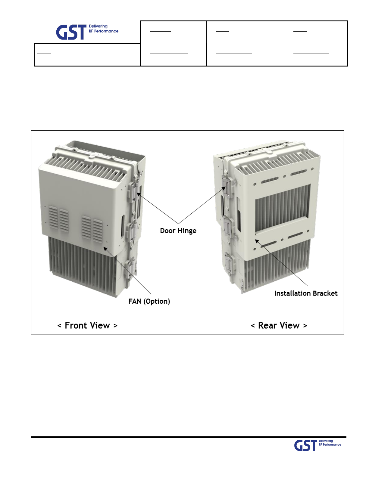
3. System Design
3.1. Perspective View
Fan may be used as an option if A is installed in an enclosed space.
Figure 2. GST-IC-ELITE-TNR Perspective View
Page 11
Version
1.1
Date
January 28th, 2019
Page
11/ 47
Title
USER MANUAL
Prepared by
Reviewed by
Approved by
© 2019 GS Teletech Inc. All rights reserved
11
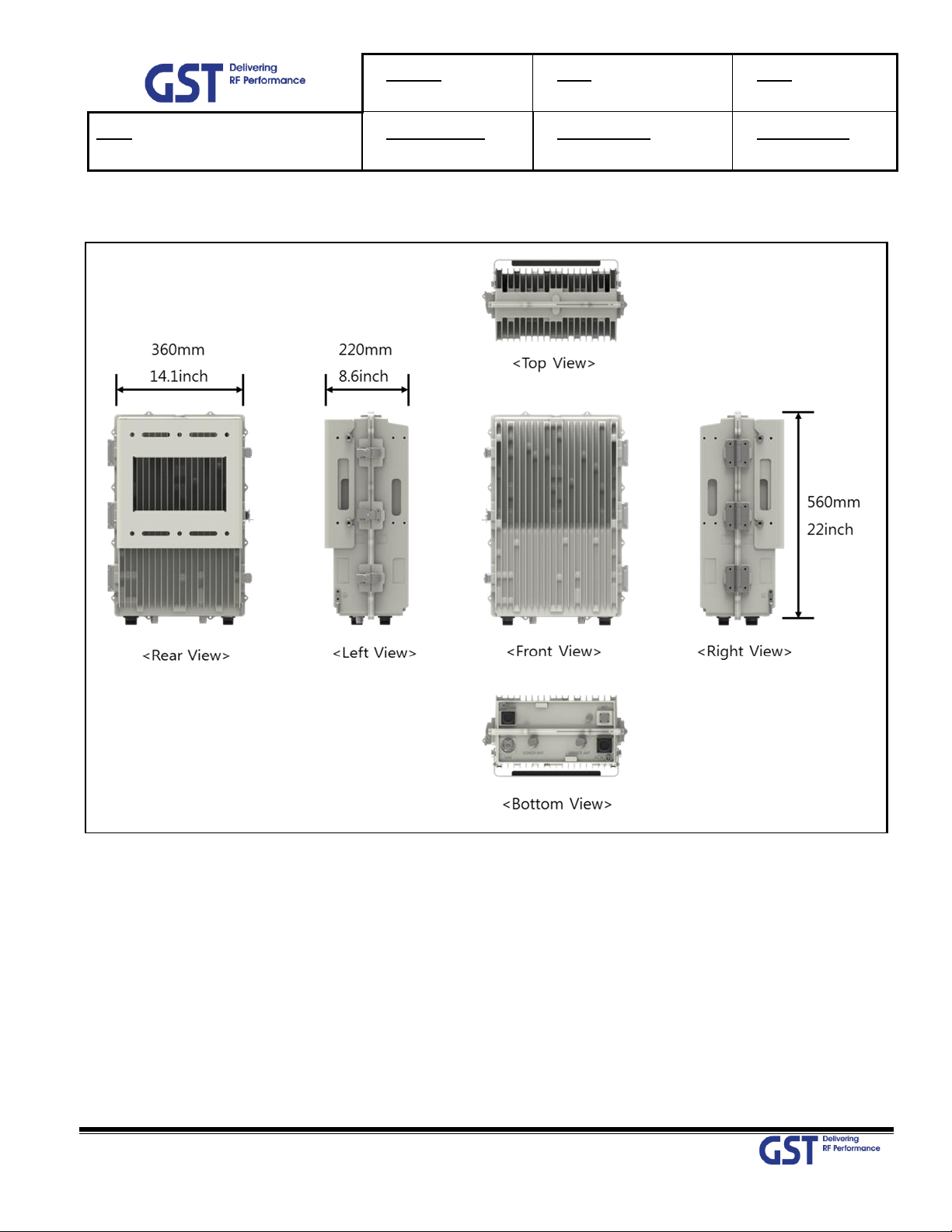
3.2. Exterior View
Figure 3. GST-IC-ELITE-TNR Exterior View
Page 12
Version
1.1
Date
January 28th, 2019
Page
12/ 47
Title
USER MANUAL
Prepared by
Reviewed by
Approved by
© 2019 GS Teletech Inc. All rights reserved
12
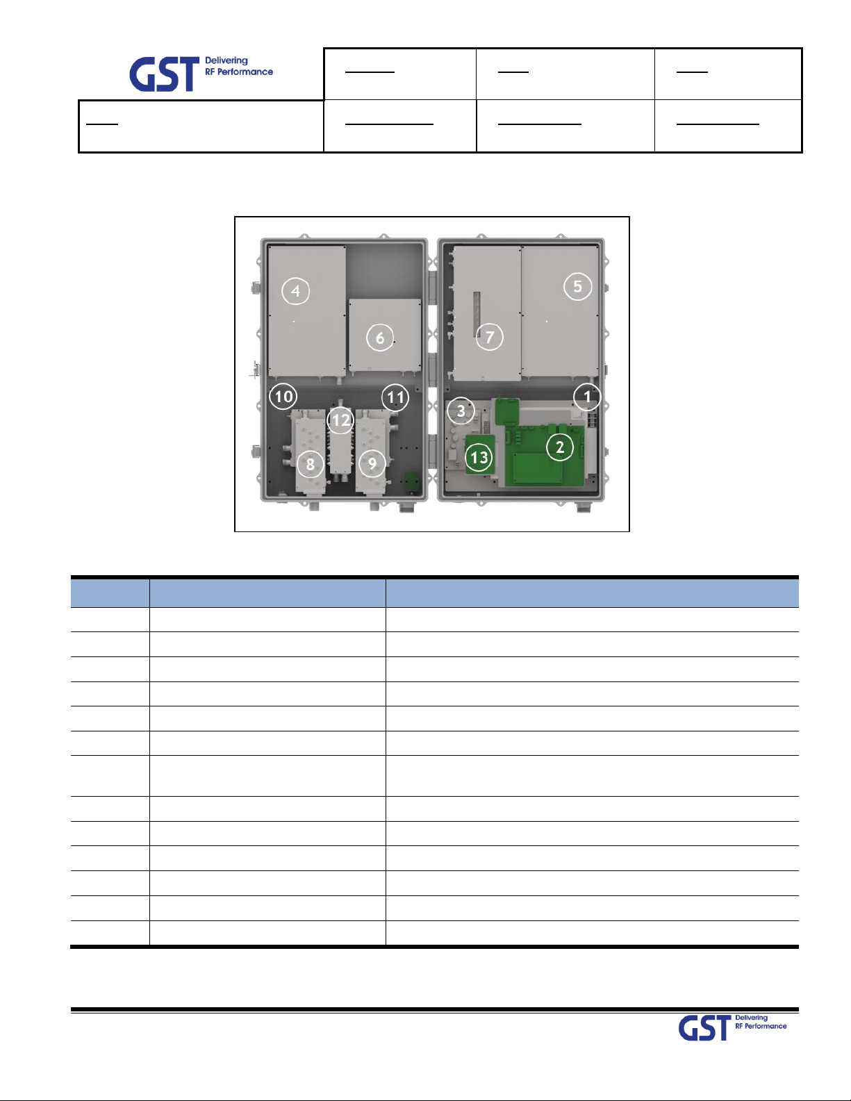
No
Name
Remark
1
Power Supply Unit
Input: 110Vac~240Vac/ Output (DC):+29V, +6V
2
SNMP Board
For EMS using Wireless Modem
3
Surge Protect Board
RET Surge Protection
4
Power Amplifier for LTE
For generating Downlink High RF Power
5
Power Amplifier for NR
For generating Downlink High RF Power
6
Power Amplifier for LTE & NR
For generating Uplink High RF Power
7
DFM
(Digital Filter Module)
Contains RF Up & Down Convertor, Digital Signal Processing
and Controller Unit
8
Band Pass Filter for Donor
Filtering for Band41 for Donor interface
9
Band Pass Filter for Service
Filtering for Band41 for Service interface
10
Donor Switching Module
Separate downlink & uplink for Donor
11
Service Switching Module
Separate downlink & uplink for Service
12
Combiner
Downlink power combiner for LTE & NR
13
EMS Modem
For Status Monitoring and Control from Server
3.3. Interior View (Outdoor)
Figure 4. GST-IC-ELITE-TNR Interior View(Outdoor)
Table 1. GST-IC-ELITE-TNR Unit Configuration
Page 13
Version
1.1
Date
January 28th, 2019
Page
13/ 47
Title
USER MANUAL
Prepared by
Reviewed by
Approved by
© 2019 GS Teletech Inc. All rights reserved
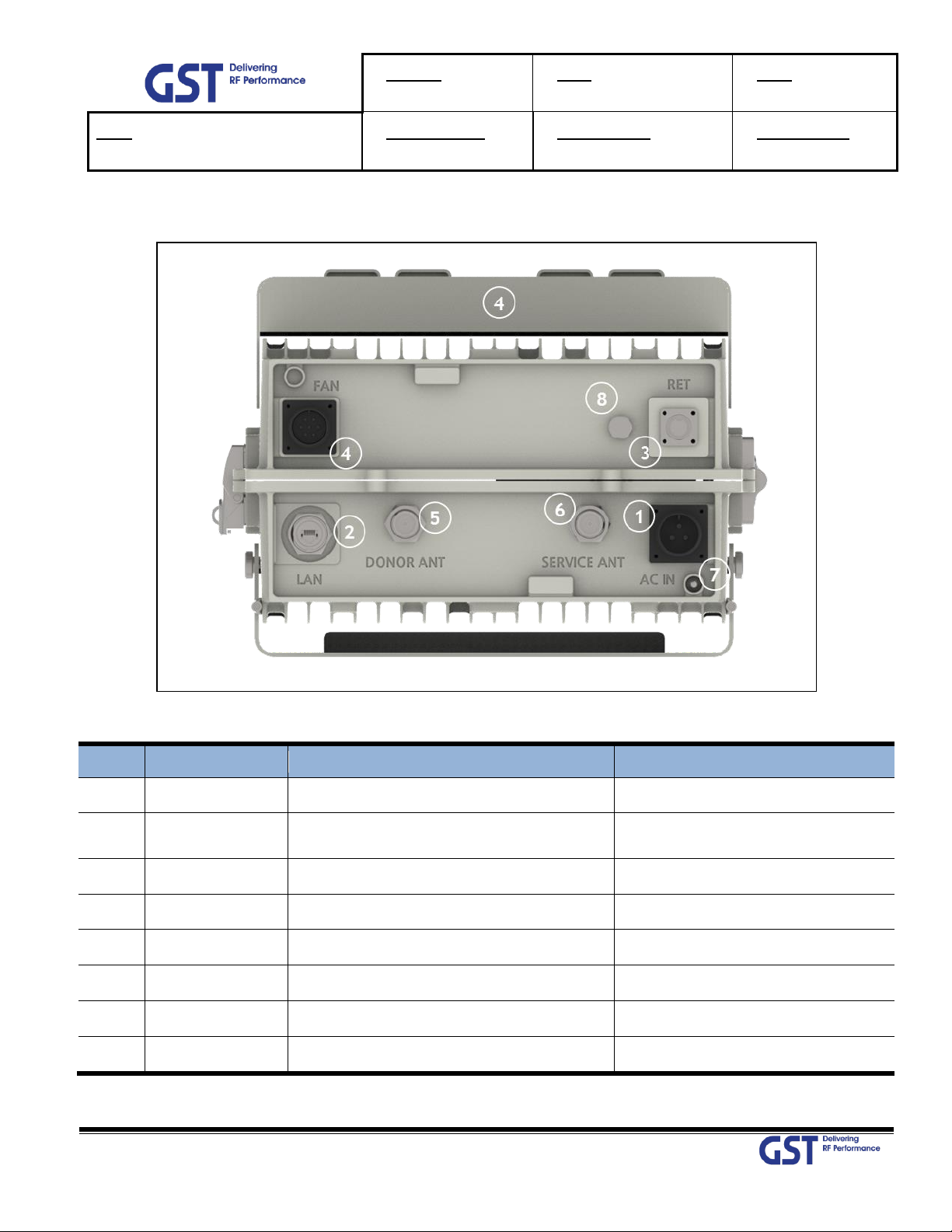
13
No
NAMES
DESCRIPTION
SPECIFICATION
1
AC IN
AC Power Input Port
MS22-2-3P
2
RJ-45
Local Maintenance or communication
other equipment of GST
Local: RJ-45
3
RET
Remote Antenna Control Port (AISG 2.0)
SU20SPR-8S/ 29V_1.5A max
4
FAN
FAN Power & Alarm Connection
MS20-15-7P
5
Donor ANT
Donor Antenna Connection
4.3-10 Mini- DIN Female
6
Service ANT
Service Antenna Connection
4.3-10 Mini- DIN Female
7
LED
System Total Alarm Indication
General Performance
8
Vent-Core
Maintain Humidity & Temp Inside
IP66
3.4. External Interface (Indoor & Outdoor)
Figure 5. GST-IC-ELITE-TNR External Interface
Table 2. GST-IC-ELITE-TNR External Interface Description
Page 14
Version
1.1
Date
January 28th, 2019
Page
14/ 47
Title
USER MANUAL
Prepared by
Reviewed by
Approved by
© 2019 GS Teletech Inc. All rights reserved
14
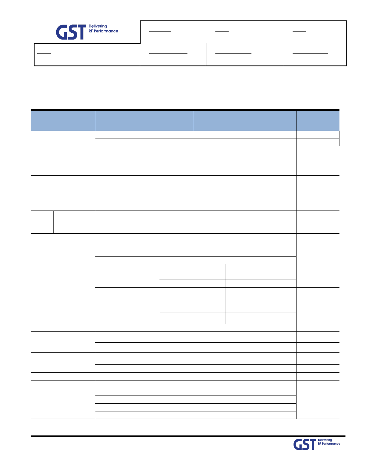
Parameter
Downlink
Uplink
Remark
Frequency Range
2496.3 ~ 2690MHz @ 100KHz Step
LTE
2496.3 ~ 2690MHz @ 100KHz Step
NR
Input Range
-55dBm ~ -25dBm/Service
-65dBm ~ -35dBm/Service
Output Power
+40dBm (10W) max
for LTE & NR
+30dBm (1W) max
for LTE & NR
Output Power
Tolerance
+40dBm ±1dBm (10W ±0.0012W)
for LTE & NR
+30dBm ±1dBm (1W ±0.0012W)
for LTE & NR
Channel Capacity
BW 20MHz * Contiguous 3CH
LTE
NR
Gain
Range
65dB ~ 95dB (Max 30dB)
ALC: 30dB
Adjust Step
0.5dB
Accuracy
±1dB
Ripple
6dB p-p @ each CH
Roll off
> 50dBc @ Channel OBW ±1MHz
LTE
> 30dBc @ Channel OBW ±1MHz
NR
> 50dBc @ Channel OBW ±1.5MHz
EVM
Max/ Min Input
QPSK
18.5%
LTE
16QAM
13.5%
64QAM
9%
Max/ Min Input
QPSK
18.5%
NR
16QAM
13.5%
64QAM
9%
256AQAM
4.5%
Frequency Error
< 0.05ppm
System Delay
< 4us
LTE
< 2.41us
NR
Noise Figure
Less than 5dB @ Max Gain
DL
Less than 5dB @ Max & Min Gain
UL
VSWR
< 1.5 : 1
ACLR
> 45dBc @±BW, > 45dBc @±2*BW
Spurious Emission
-13dBm / 1 kHz: 9 kHz < f < 150 kHz
ITU
category A
-13dBm / 10 kHz: 150 kHz < f < 30 MHz
-13dBm/100 kHz: 30 MHz < f < 1 GHz
-13dBm / 1 MHz: 1 GHz < f < 12.75 GHz
4. System Specification
4.1. RF Performance
BW60MHz
Table 3. GST-IC-ELITE-TNR RF Performance Description
Page 15
Version
1.1
Date
January 28th, 2019
Page
15/ 47
Title
USER MANUAL
Prepared by
Reviewed by
Approved by
© 2019 GS Teletech Inc. All rights reserved
15
No.
Parameter
Condition
Specification
1
Gain Re-Tracking Time after reset
Target Gain ±1dB
< 30 Sec
2
Isolation Sensing Range
-10dB < Gain < 10dB
Accuracy ±2
3
G = I + 10dB
Static
General Operating
4
G = I
10Hz
Fast Fading
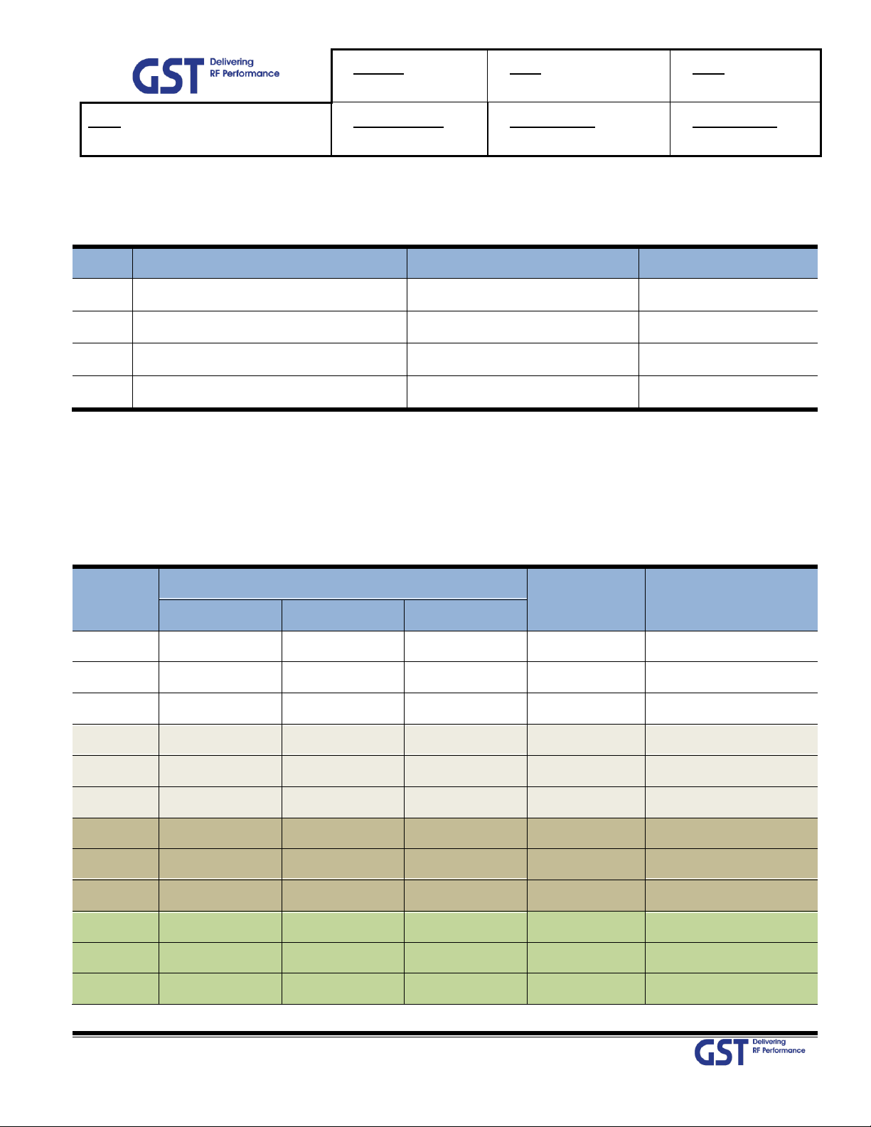
CH
Name
Channel Frequency
BW(MHz)
EARFCN
Start(MHz)
Center(MHz)
Stop(MHz)
L01
2505.3
2514.3
2523.3
18
39833
L02
2525.1
2534.1
2543.1
18
40031
L03
2544.9
2553.9
2562.9
18
40229
L06
2619.8
2628.8
2637.8
18
40978
L07
2639.6
2648.6
2657.6
18
41176
L08
2659.4
2668.4
2677.4
18
41374
L13
2623.3
2632.3
2641.3
18
41013
L14
2643.1
2652.1
2661.1
18
41211
L15
2662.9
2671.9
2680.9
18
41409
L20
2626.6
2635.6
2644.6
18
41046
L21
2646.4
2655.4
2664.4
18
41244
L22
2666.2
2675.2
2684.2
18
41442
4.2. ICS General Performance
Table 4. GST-IC-ELITE-TNR ICS General Performance
4.3. CH Capacity Information
4.3.1. LTE Band 41
• Maximum configurable channel is contiguous 3channel
Page 16

Version
1.1
Date
January 28th, 2019
Page
16/ 47
Title
USER MANUAL
Prepared by
Reviewed by
Approved by
© 2019 GS Teletech Inc. All rights reserved
16
CH
Name
Channel Frequency
BW(MHz)
EARFCN
Start(MHz)
Center(MHz)
Stop(MHz)
L27
2629.8
2638.8
2647.8
18
41078
L28
2649.6
2658.6
2667.6
18
41276
L29
2669.4
2678.4
2687.4
18
41474
L32
2613.3
2622.3
2631.3
18
40913
L33
2633.1
2642.1
2651.1
18
41111
L34
2652.9
2661.9
2670.9
18
41309
L37
2616.8
2625.8
2634.8
18
40942
L38
2636.6
2645.6
2654.6
18
41146
L39
2656.4
2665.4
2674.4
18
41344
L53
2631.4
2640.4
2649.4
18
41094
L54
2651.2
2660.2
2669.2
18
41292
L55
2671.0
2680.0
2689.0
18
41490
BW
Center FRQ Range(100KHz step)
NR-ARFCN Range
Start(MHz)
Stop(MHz)
Start
Stop
60MHz
2526.3
2660
505260
532000
4.3.2. NR Band N41
Table 5. GST-IC-ELITE-TNR Operation Band for LTE Band 41
Table 6. GST-IC-ELITE-TNR Operation Band for NR Band N41
Page 17

Version
1.1
Date
January 28th, 2019
Page
17/ 47
Title
USER MANUAL
Prepared by
Reviewed by
Approved by
© 2019 GS Teletech Inc. All rights reserved
17
Parameter
Specification
Remark
Donor/ Service
Antenna Filter
Band Pass type for LTE & NR
Time Division
Power Supply
AC Input Voltage: 110~240V (50/60Hz)
DC Output Voltage: +29V / +6V
Operation Temperature
-30°C~+50°C (100%RH)
Storage Temperature
-40°C~+85°C (5~95%RH)
Connectors
Antenna: 4.3-10MiniDIN Female
On Bottom side
Ethernet: RJ-45
AC: MS22-2-3P
FAN: MS20-15-7P
RET: SU20SPR
Size
22" x 14.1" x 8.6"(560mm x 360mm x 220mm)
Without Bracket
Weigh
Less than 30kg (66lb)
Without Bracket
Power Consumption
Less than 360W
MTBF
100,000 hours or higher
Internal Modem
LTE Modem primary
Back up with CDMA Modem
RET
Provide a physical Connection & 29V/1.5Amax
AISG 2.0 Standard
Dust Resistance
Telcordia GR63-CORE
Vibration Resistance
1G, 10~150Hz, 0.1 Octaves/min
Grounding
nonferrous metal and anchoring point on bottom sid
e
For RF and power cabling
Environmental Spec.
NEMA4
IP 66
Sustained winds.
150mph
Altitude
AMSL 10,000ft
Mount Application
Metal or Wooden Poles
8"-20" outside diameter
Pollution degree
PD2
Overvoltage Category
OVC II
4.5. Configuration & Mechanical Specification
Table 7. GST-IC-ELITE-TNR Mechanical & Environment conditions
Page 18

Version
1.1
Date
January 28th, 2019
Page
18/ 47
Title
USER MANUAL
Prepared by
Reviewed by
Approved by
© 2019 GS Teletech Inc. All rights reserved
18
No
RF Signal Flow
No
RF Signal Flow
1
DL Input & UL Output
8
DL Output & UL Input
2
Donor Switch -> DL RF Module
9
Service Switch -> UL RF Module
3
DL RF Module -> DL LTE AMP
10
UL RF Module -> UL AMP
4
DL RF Module -> DL NR AMP
11
UL AMP -> Donor Switch
5
DL LTE AMP -> Combiner
12
LTE DL Reference F/B
6
DL NR AMP -> Combiner
13
NR DL Reference F/B
7
Combiner -> Service Switch
5. System Block Configuration
5.1. RF Signal Flow (Outdoor)
Figure 6. GST-IC-ELITE-TNR RF Signal Flow (Outdoor)
Table 8. GST-IC-ELITE-TNR RF Signal Flow (Outdoor)
Page 19

Version
1.1
Date
January 28th, 2019
Page
19/ 47
Title
USER MANUAL
Prepared by
Reviewed by
Approved by
© 2019 GS Teletech Inc. All rights reserved
19
No
Data signal Flow
No
Data signal Flow
1
LTE DL AMP <-> DFM (LvTTL)
6
Donor Switch Control <-> DFM
2
NR DL AMP <-> DFM (LvTTL)
7
Service Switch Control <-> DFM
3
UL AMP <-> DFM
8
Fan Control <-> DFM
4
SMPS Alarm <-> DFM
9
LED Board <-> SNMP Board
5
DFM <-> SNMP Board(LvTTL)
10
RET Control Data
5.2. Data Signal Flow
Figure 7. GST-IC-ELITE-TNR Signal and Data Flow
Table 9. GST-IC-ELITE-TNR Data Signal Flow
Page 20

Version
1.1
Date
January 28th, 2019
Page
20/ 47
Title
USER MANUAL
Prepared by
Reviewed by
Approved by
© 2019 GS Teletech Inc. All rights reserved
20
No
Power Flow
No
Power Flow
1
AC 110V Input for SMPS
8
Supply 24V for FAN
2
Supply 29V for LTE DL AMP
9
Supply 6V for Donor Switch
3
Supply 29V for NR DL AMP
10
Supply 6V for Service Switch
4
Supply 29V & 6V for UL AMP
11
Supply 6V for RF Module
5
Supply 29V for RET Board
12
Supply 6V for DSP Module
6
Supply 29V for RET
13
Supply 6V for SNMP Board
7
Supply 29V for FAN Controller
5.3. Power Supply Flow
Figure 8. GST-IC-ELITE-TNR Power Supply Flow
Table 10. GST-IC-ELITE-TNR Power Supply Flow
Page 21

Version
1.1
Date
January 28th, 2019
Page
21/ 47
Title
USER MANUAL
Prepared by
Reviewed by
Approved by
© 2019 GS Teletech Inc. All rights reserved
21
Parameter
Status
Control
Description
Downlink
RSSI
○
DL Input Power Display
Output
○
DL Output Power Display
System Gain
○
DL System Gain Display
ALC
○
Set the ALC function On/Off
ALC Low Limit
○
Set the ALC Low Limit Value
Path On/Off
○
Decide to cut off to LTE or NR
Attenuation
○
In order to adjust system gain,
set the attenuation value
Isolation (Unit: dB)
○
Display the isolation value between
Donor antenna and Service antenna
Band Selection
○ Select the band that user want to operate
Final AMP
○ Set the High Power final AMP On/Off
ASD
○ Set the Auto Shutdown function On/Off
Uplink
RSSI
○
UL Input Power Display
Output
○
UL Output Power Display
System Gain
○
UL System Gain Display
ALC
○ Set the UL ALC function On/Off
Path On/Off
○
Decide to cut off LTE or NR
Attenuation
○
In order to adjust system gain,
set the attenuation value
Isolation (Unit: dB)
○
Display the isolation value between
Donor antenna and Service antenna
Gain Balance
○
Select the band that user want to operate
& Set the Offset Value
Final AMP
○ Set the High Power final AMP On/Off
ASD
○ Set the Auto Shutdown function On/Off
Common
Site ID
○ Write the location Info. that install a repeater
6. Status/ Control & Alarm Monitoring
6.1. Status Monitoring and Control Parameters
• In case of control parameter, present status but also setting value display on Web-UI.
Page 22

Version
1.1
Date
January 28th, 2019
Page
22/ 47
Title
USER MANUAL
Prepared by
Reviewed by
Approved by
© 2019 GS Teletech Inc. All rights reserved
22
Parameter
Status
Control
Description
Donor Site ID
○ Write the Donor Site Info. That install a repeater
Temp
○
Current Temperature in repeater
Temp. High Limit
○
Control Temp. Alarm Threshold
ILC
○
ILC Function On/Off
ILC Value
○
ILC Level Control
Alarm Delay
○
Set the delay time that transmit from
repeater to Server
UL AMP
○
UL AMP On Off
DFM Version
○
Display a DFM Software Version
FPGA Version
○
Display a DL/UL FPGA Software Version
DFM Serial Number
○
Display a DFM Serial Number
TDD Mode
○
T-Sync Detect Mode Control
Parameter
Alarm conditions
Recovery
LTE
DL Over Output
Output power exceed a setting value (Band
independently)
< Hysteresis 1dB
DL Low Output
Band Output power < Output power Low limit value
Opposite Condition
DL Low RSSI
Band RSSI < Input Low limit value
Opposite Condition
DL VSWR
Return loss < 5dB
Return loss > 7dB
DL Shutdown
By Over Output Alarm, By PLL Alarm, By Amp H/W Fail
By Low Isolation
Alarm Off
AMP H/W Fail
Power AMP gain is poor
AMP Output Power < DSP Output Power -20dB over 30sec
Power AMP Gain OK
DL Low Isolation
Isolation < 70dB
Opposite Condition
UL Low Isolation
Isolation < 70dB
Opposite Condition
Table 11. GST-IC-ELITE-TNR Status Monitoring and Control Parameters
6.2. Alarm Monitoring
• All of alarms in Repeater are able to check thru Local Maintenance Port & Remote Site
• Provide to Alarm Mask function in order to ignoring unnecessary alarm
Page 23

Version
1.1
Date
January 28th, 2019
Page
23/ 47
Title
USER MANUAL
Prepared by
Reviewed by
Approved by
© 2019 GS Teletech Inc. All rights reserved
23
Parameter
Alarm conditions
Recovery
UL Over Output
Output power Exceed a setting value (Band
independently)
< Hysteresis 2dB
NR
DL Over Output
Output power exceed a setting value (Band
independently)
< Hysteresis 1dB
DL Low Output
Band Output power < Output power Low limit value
Opposite Condition
DL Low RSSI
Band RSSI < Input Low limit value
Opposite Condition
DL VSWR
Return loss < 5dB
Return loss > 7dB
DL Shutdown
By Over Output Alarm, By PLL Alarm, By Amp H/W Fail
By Low Isolation
Alarm Off
AMP H/W Fail
Power AMP gain is poor
AMP Output Power < DSP Output Power -20dB over 30sec
Power AMP Gain OK
DL Low Isolation
Isolation < 70dB
Opposite Condition
UL Low Isolation
Isolation < 70dB
Opposite Condition
UL Over Output
Output power Exceed a setting value (Band
independently)
< Hysteresis 2dB
Common
DFM HW Fail
DFM FPGA Fail (Judging from MCU, Except for RESET)
DL/ UL Output Shutdown
Alarm & Power
Recovery
DFM Link Fail
Communication Fail between DFM & SNMP
Communication
T-Sync Alarm
TDD Downlink Signal is not detected over 30sec
Signal is detected
over 30sec
T-Sync Link Fail
No response more than 10times
At once
Temperature
System: REAL Temp>Setting Value
Refer to Final Amp Temperature
: Alarm: 85℃~90℃/ Shutdown: > 90℃
System: Opposite
Final Amp: < 80℃
DC Fail
Output voltage below 80%
DC Recovery
UL VSWR
Return loss < 5dB
Return loss > 7dB
Total Alarm Display
Only System Outside LED
Table 12. Monitoring Alarm Parameters
Page 24

Version
1.1
Date
January 28th, 2019
Page
24/ 47
Title
USER MANUAL
Prepared by
Reviewed by
Approved by
© 2019 GS Teletech Inc. All rights reserved
24
1. Go to Local Connection
2. Click on "Properties"
3. Highlight "Internet Protocol"
4. Click on "Properties"
5. Choose "Obtain DNS Server
address automatically"
6. Clink OK
7. Web-UI Overview
• Provide all functions that can be performed at the local craft port will be available thru the remote interface
• Support the GUI pages that will be addressable via the LTE/ CDMA wireless modem
• Support Remote access that will enable troubleshooting down to a specific location
7.1. Configuration the Laptop to Connect to the Repeater
• Connect an Ethernet crossover cable from the LAN port of the repeater’s bottom side to your laptop
Figure 9. Laptop Configuration for connecting the Web-UI
Page 25

Version
1.1
Date
January 28th, 2019
Page
25/ 47
Title
USER MANUAL
Prepared by
Reviewed by
Approved by
© 2019 GS Teletech Inc. All rights reserved
25
Write a Use ID and Password
7.2. Login-In Screen
• Web-UI Screen for Log-In
• After Logging, User can be able to operate Web-UI
• Register & Delete a User name/ Password: Refer to 8.6 User Management
• Display Total Alarm & Shutdown Status
• Enter the IP Address "192.168.1.1" into your browser address bar and you will be redirected to the Login page
Figure 10. The way to Log-in on the Web Browser Screen
Page 26

Version
1.1
Date
January 28th, 2019
Page
26/ 47
Title
USER MANUAL
Prepared by
Reviewed by
Approved by
© 2019 GS Teletech Inc. All rights reserved
26
7.3. RF Status & Control
• Web-UI Screen for display Repeater’s RF Status & Control window
Figure 11. RF Status monitoring & Control
Page 27

Version
1.1
Date
January 28th, 2019
Page
27/ 47
Title
USER MANUAL
Prepared by
Reviewed by
Approved by
© 2019 GS Teletech Inc. All rights reserved
27
7.4. Alarm Configuration
• Web-UI Screen for Alarm Configurations
• Decide to activate an each alarm
• When "Report Alarm" is OFF, all alarms are disabled. When "Report Alarm" is ON, alarms can be Enable/ disabled
individually
Figure 12. System Alarm Configurations
Page 28

Version
1.1
Date
January 28th, 2019
Page
28/ 47
Title
USER MANUAL
Prepared by
Reviewed by
Approved by
© 2019 GS Teletech Inc. All rights reserved
28
7.5. Communication Configuration
• Web-UI Screen for Communication Configurations
• Set the information in order to connect to Sprint Server
• On this page you can change the various values related to IP network. Because the Web-UI is based on the IP
network, incorrect configuration may make it impossible to connect to the Web-UI.
• In that case, Contact GSTeletechinc Technical Support for further instructions
Figure 13. System Information for connecting configurations
Page 29

Version
1.1
Date
January 28th, 2019
Page
29/ 47
Title
USER MANUAL
Prepared by
Reviewed by
Approved by
© 2019 GS Teletech Inc. All rights reserved
29
7.6. User Management
• Web-UI Screen for Management about user information
• On this page you can create and delete users, change passwords, and assign authorities to individual users
• Read Authority will only allow the user to view information on the menu pages, but cannot make any changes
• Read/ Write Authority means the user can view and change various values
• Super User is very similar to and Administrator account
Figure 14. System Information about User Management
Page 30

Version
1.1
Date
January 28th, 2019
Page
30/ 47
Title
USER MANUAL
Prepared by
Reviewed by
Approved by
© 2019 GS Teletech Inc. All rights reserved
30
7.7. Alarm Log
• Web-UI Screen for finding Alarm log
• You can see the history of reported and reset Alarms. When an alarm is reported, the name and time of the alarm
is displayed along with its current status
• Red means the alarm is reported, Green means the alarm has returned to normal status
• An alarm will only be reported if the alarm condition lasts longer that the set value in the "Delay Alarm Reporting
Minutes" field, found on the RF configuration page
Figure 15. The way to check System Alarm Log
Page 31

Version
1.1
Date
January 28th, 2019
Page
31/ 47
Title
USER MANUAL
Prepared by
Reviewed by
Approved by
© 2019 GS Teletech Inc. All rights reserved
31
7.8. Log
• Web-UI Screen for reading a List of operation history
• Logs will maintain a history of up to 30 cycles
Figure 16. The way to read a Log History
Page 32

Version
1.1
Date
January 28th, 2019
Page
32/ 47
Title
USER MANUAL
Prepared by
Reviewed by
Approved by
© 2019 GS Teletech Inc. All rights reserved
32
7.9. Troubleshooting
• Web-UI Screen for informing a contact information in case of occurring Field Troubleshooting
Figure 17. The information of Contact point in case of occurring Field Troubleshooting
Page 33

Version
1.1
Date
January 28th, 2019
Page
33/ 47
Title
USER MANUAL
Prepared by
Reviewed by
Approved by
© 2019 GS Teletech Inc. All rights reserved
33
7.10. Software Update
• Web-UI Screen for downloading a software
• Procedure
1) Go to "Remote Software Upgrade" link
2) Click Browse button to select the upgrade file from the laptop
3) Choose the file to upgrade. Provided by manufacturer. After you choose the file, You should click "upload"
to send the file from your laptop to the Repeater
4) Once the file name and file size are displayed, click "Upgrade" to start the upgrade installation
5) Provided file will have the following format:
Figure 18. The way to reload new software using the Web-UI
Page 34

Version
1.1
Date
January 28th, 2019
Page
34/ 47
Title
USER MANUAL
Prepared by
Reviewed by
Approved by
© 2019 GS Teletech Inc. All rights reserved
34
7.11. System Reset
• Web-UI Screen for resetting the system
• Click on the desired reset action
• Clink "Yes" to reset the repeater via a soft-boot. This will not change any of the current settings
Figure 19. The way to reset the system using the Web-UI
Page 35

Version
1.1
Date
January 28th, 2019
Page
35/ 47
Title
USER MANUAL
Prepared by
Reviewed by
Approved by
© 2019 GS Teletech Inc. All rights reserved
35
7.12. Factory Default Setting
• Web-UI Screen for Default Setting before operating
Figure 20. The way to restore Factory Default Setting for repeater
Page 36

Version
1.1
Date
January 28th, 2019
Page
36/ 47
Title
USER MANUAL
Prepared by
Reviewed by
Approved by
© 2019 GS Teletech Inc. All rights reserved
36
7.13. Configuration Transfer
• Web-UI Screen for mutual information transfer between Repeater and Local Craft
Figure 21. The way to down/ up load configuration between laptop and repeater
Page 37

Version
1.1
Date
January 28th, 2019
Page
37/ 47
Title
USER MANUAL
Prepared by
Reviewed by
Approved by
© 2019 GS Teletech Inc. All rights reserved
37
#
Contents
Picture
Q’ty
1
Mounting Bracket (wall mount)
1EA
2
AC Power Cable SJT AWG, 6ft
1EA
3
Installation purchase
M6x15mm BOLT, SEMS
4EA
4
Mounting Screw set
LAG SCREW 3/8”x5”, SCM440
4EA
LAG SCREW 3/8”x2”, SCM440
4EA
HEX BOLT 3/8”x2”, SCM440
4EA
HEX NUT 3/8”, SCM440
8EA
Φ10.5mm/Φ21mm PLAIN WASHER
12EA
Φ10.2mm/Φ18.4mm SPRING WASHER
8EA
8. System Installation
• This chapter describes how to install the repeater and Cabling method
• The needed accessories and tools are list up as below
• More detailed information about installation, refer to the MOP(Manufacturer Operating Process)
Table 13. GST-Ic-ELITE-TNR Installation Accessories
Page 38

Version
1.1
Date
January 28th, 2019
Page
38/ 47
Title
USER MANUAL
Prepared by
Reviewed by
Approved by
© 2019 GS Teletech Inc. All rights reserved
38
8.1. Warnings and Hazards
8.1.1. Electric Shock
• Opening the Repeater could result in electrical shock and may cause severe
injury
• Operating the Repeater with antennas in very close proximity facing each other
could lead to severe damage to the repeater
8.1.2. Exposure to RF
Working with the repeater while in operation, may expose the technician to
RF electromagnetic fields that exceed FCC Rules for human expose.
Visit the FCC Website at http://www.fcc.gov/oet/rfsafety to learn more about
The effects of exposure to RF electromagnetic fields
Page 39

Version
1.1
Date
January 28th, 2019
Page
39/ 47
Title
USER MANUAL
Prepared by
Reviewed by
Approved by
© 2019 GS Teletech Inc. All rights reserved
39
From
To
Cable
GST-IC-ELITE TNR
MGB
Frame Ground Cable: AWG 6/ 6ft
Circuit Breaker Box
AC Power Cable: AWG 16/ 6ft
RF Antennas
RF Antenna Feeder Cable: 1/2 inch Feeder Line
RET control Cable (option)
8.2. Cabling
The cabling diagram of the GST-IC-ELITE TNR-Indoor is as follows
Figure 22. GST-IC-ELITE-TNR-Outdoor Cabling Diagram
Table 14. GST-IC-ELITE-TNR-Outdoor Connecting Cable
Page 40

Version
1.1
Date
January 28th, 2019
Page
40/ 47
Title
USER MANUAL
Prepared by
Reviewed by
Approved by
© 2019 GS Teletech Inc. All rights reserved
40
No use for the unauthorized device
When installing the system, must check the devices that use is authorized.
This conditions apply antenna, cable and coupling device if necessary.
Circuit Breaker Installation in the Box for Overcurrent Protection
Must install the circuit breaker between the system and main AC source for separating.
Make sure to install the Circuit breaker on the place to operate easily
Circuit Breaker is able to operate up to 20A
and do not exceeds a distance from circuit breaker box to repeater is 5ft
Terminal, Conduit and Cable Size
To install the conduit is according to NAE regulation, and Terminal sixe is according to
NEC regulation
Page 41

Version
1.1
Date
January 28th, 2019
Page
41/ 47
Title
USER MANUAL
Prepared by
Reviewed by
Approved by
© 2019 GS Teletech Inc. All rights reserved
41
8.3. Installation Guide for Crew
8.3.1. Wall Mount Installation
The procedure for fixing the wall type system is as follows:
1) Wall Mounting Bracket Shape
Figure 23. Mounting Bracket Shape
Page 42

Version
1.1
Date
January 28th, 2019
Page
42/ 47
Title
USER MANUAL
Prepared by
Reviewed by
Approved by
© 2019 GS Teletech Inc. All rights reserved
42
Wall Thickness
Wall thickness to fix the system is 1.5 inch over at least.
2) To mount the system on the wall, first fix the bracket on the wanted position
Figure 24. Fixing the Bracket for installing a Wall Mount
Page 43

Version
1.1
Date
January 28th, 2019
Page
43/ 47
Title
USER MANUAL
Prepared by
Reviewed by
Approved by
© 2019 GS Teletech Inc. All rights reserved
43
3) Hang the system to the hooking position at the top of the mounting bracket
Figure 25. The way to hang the system for Wall Mounting
4) Align the system with the fixing holes of the mounting bracket and fix them firmly
Figure 26. The way to fix firmly the System for Wall Mounting
Page 44

Version
1.1
Date
January 28th, 2019
Page
44/ 47
Title
USER MANUAL
Prepared by
Reviewed by
Approved by
© 2019 GS Teletech Inc. All rights reserved
44
Port Outlook
(Fixed Side)
Port numbering
NAME
Description
MS-3102A-10SL-3P
A
AC_H
AC Hot
B
AC_N
AC Neutral
C
F.G
Frame Ground
Port Outlook
(Fixed Side)
Port numbering
NAME
Description
MS3102A14S-2P
A
RED
+24 VDC
B
RED
+24 VDC
C
BLACK
GND
D
BLACK
GND
E
YELLOW
FAN Alarm #1
F
YELLOW
FAN Alarm #2
8.4. Cable Connection
8.4.1. AC Power cable connection
• Repeater supports a free AC Input voltage from 110V to 220V
• The pin description of AC Port is below. User should connect exact polarity of AC
Table 15. AC Power Connector Configuration
8.4.2. FAN Power Cable Connection (OPTION)
Table 16. GST-IC-ELIT TNR FAN Power Cable Connection
Page 45

Version
1.1
Date
January 28th, 2019
Page
45/ 47
Title
USER MANUAL
Prepared by
Reviewed by
Approved by
© 2019 GS Teletech Inc. All rights reserved
45
Port Outlook
(Fixed Side)
Port numbering
NAME
Description
SU20SPR-8S
3
RS485B
Communication
4
DGND
Frame Ground
5
RS485A
Communication
6
+29 V
1.5A max
7
DC Return
Retune DC Power
1, 2, 8
NC
-
T568B Interface
8.4.3. RET Cable Connection (Option)
Table 17. GST-IC-ELIT TNR RET Cable Connection
8.4.4. Local Maintenance Connection
• Repeater Support a RJ-45 connector for local maintenance
Figure 27. RJ-45 Interface for connecting the Local Maintenance
Page 46

Version
1.1
Date
January 28th, 2019
Page
46/ 47
Title
USER MANUAL
Prepared by
Reviewed by
Approved by
© 2019 GS Teletech Inc. All rights reserved
46
Frame Ground
8.4.5. Grounding cable Connection
• JOCT 0202-RL05 Lug supports AWG #6. The way to install the grounding cable is below
Figure 28. The way to install the Frame Ground Cable and Lug specifications
Page 47

Version
1.1
Date
January 28th, 2019
Page
47/ 47
Title
USER MANUAL
Prepared by
Reviewed by
Approved by
© 2019 GS Teletech Inc. All rights reserved
47
9. FCC Warning Statement
<FCC Warning Statements>
FCC Part 15.105 statement
This equipment has been tested and found to comply with the limits for a Class A digital device, pursuant to part 15
of the FCC Rules. These limits are designed to provide reasonable protection against harmful interference when the
equipment is operated in a commercial environment. This equipment generates, uses, and can radiate radio
frequency energy and, if not installed and used in accordance with the instruction manual, may cause harmful
interference to radio communications. Operation of this equipment in a residential area is likely to cause harmful
interference in which case the user will be required to correct the interference at his own expense.
FCC Part 15.21 statement
Any changes or modifications not expressly approved by the party responsible for compliance could void the user's
authority to operate this equipment.
RF Exposure Statement
The antenna(s) must be installed such that a minimum separation distance of at least 360 cm is maintained between
the radiator (antenna) and all persons at all times. This device must not be co -located or operating in conjunction
with any other antenna or transmitter.
licensee consent
Any personnel involved in installation, operation or service of the repeaters must understand and obey the following:
- You MUST REGISTER THIS DEVICE with your wireless provider and have your provider's consent.
- If you are unsure, contact your provider
- The device can be operated for CMRS (Commercial Mobile Radio Service)
Signal booster warning label message
-. Use of unauthorized antennas, cables, and/or coupling devices not conforming with ERP/EIRP
and/or indoor‐only restrictions is prohibited.
-. Home/ personal use are prohibited
Page 48

Supplier's Declaration of Conformity
47 CFR § 2.1077 Compliance Information
Unique Identifier: IC-ELITE TNR43
Responsible Party – U.S. Contact Information
GSTeletech,Inc.
8206 Marshall Drive,
Lenexa, Kansas 66214
Contact point
Charles You
chyu@gsteletechinc.com
Office : 1-913-469-6699
Fax : 1-913-661-0163
FCC Compliance Statement (e.g., products subject to Part 15)
This device complies with Part 15 of the FCC Rules. Operation is subject to the following
two conditions: (1) This device may not cause harmful interference, and (2) this device
must accept any interference received, including interference that may cause undesired
operation.
 Loading...