

Page 1
700
850
1900
2100
HOME 5000
User Guide
www.americanbst.com
Technical Support : 913 469 6699
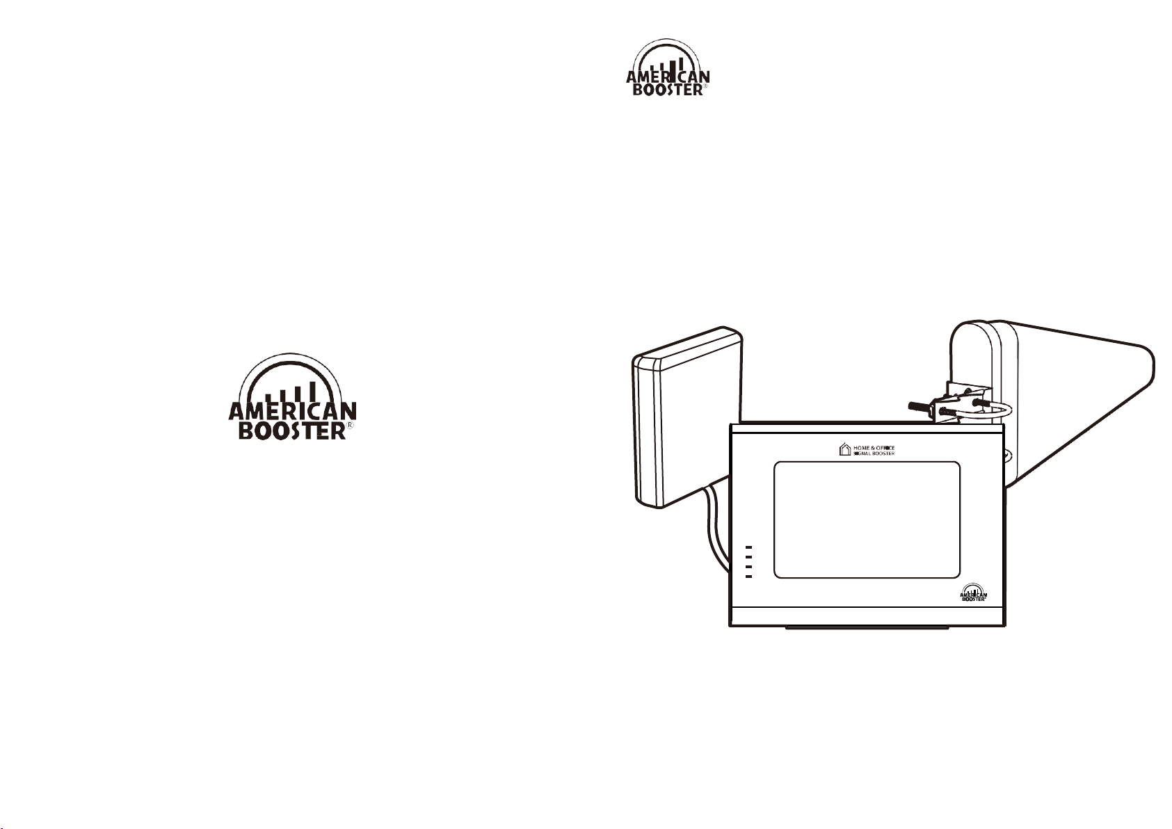
HOME Cellular Signal Booster
Page 2

Date
Version
Changes
2019, January
Version 1.0
Original
Technical Support : 913 469 6699
www.americanbst.com
Memo
This publication provides instructions for installing
Copyright© 2019, American Booster Inc.
All Rights Reserved.
Revision History
Certification
Cellular Signal Booster Home 5000.
This equipment complies with the FCC / IC directives.
HOME 5000 User Guide
23
Page 3
WARRANTY
Opening or tampering with the Signal Booster will void all warranties.
American Booster provides a 2-year warranty with all of its equipment.
Every product of American Booster is guaranteed to be free of material defects or component
malfunctions.
This warranty does not cover any Signal Boosters that have been exposed to any misuse, abuse,
physical damage or inadequate maintenance.
Products returned by customers must be in their original, unmodified condition, shipped in the
original packaging with proof of purchase documentation enclosed, and a Return Merchandise
Authorization (RMA) number printed on the outside of the shipping box.
To repair or replace damaged Signal Boosters we may include refurbished American Booster’s products.
INDEX
Product Introduction
Package Contents
Application Example
HOME 5000 Optional Kit
Installation Guide
STEP 1. Find the Strongest Signal
STEP 2. Install the Outside Antenna
4
5
6
7
8
8
10
STEP 3. Run the Outside Antenna Cable
STEP 4. Run the Cable to the Booster
STEP 5. Install the Inside Antenna
STEP 6. Install the Signal Booster
LED Indicators
Troubleshooting
Specifications
16
17
18
13
14
15
12
Safety Guidelines
FCC Warning Statements
130 E Covey Run, Union, WA 98592
Technical Support : 913 469 6699 www.americanbst.com
22
HOME 5000 User Guide
IC Warning Statements
Warranty
Memo
19
20
21
22
23
Page 4
4 21
HOME 5000 User Guide
HOME 5000 User Guide
700
850
1900
2100
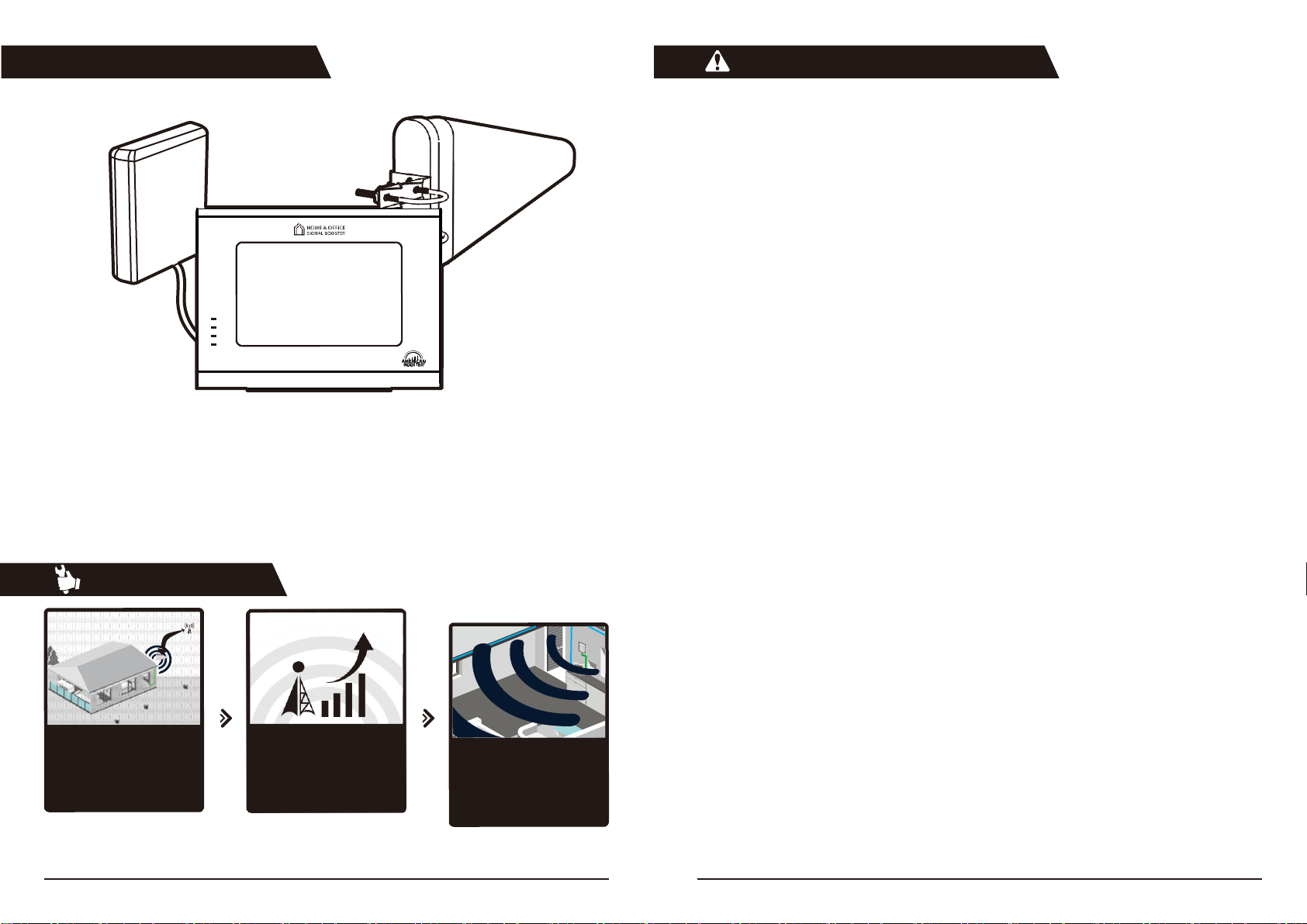
How it works
Receives Signal
The signal booster’s outside
antenna receives voice and
data signals from a nearby
cell tower.
Boosts Signal
The signal booster receives
the signal from the outside
antenna and amplifi the voice
and data signals.
Distributes Signal
The boosted signals are
distributed inside your
house/office.
IC Warning Statements
HOME 5000
American Booster® Home 5000 has been designed to provide an advanced solution for boosting your
signal and increasing the cellular data speeds in your house or office.
RSS-GEN, Sec. 7.1.2 – (transmitters)
Under Industry Canada regulations, this radio transmitter may only operate using an antenna of a type and maximum
(or lesser) gain approved for the transmitter by Industry Canada. To reduce potential radio interference to other users,
the antenna type and its gain should be so chosen that the equivalent isotropically radiated power (e.i.r.p.) is not more
than that necessary for successful communication.
Conformément à la réglementation d’Industrie Canada, le présent émetteur radio peut fonctionneravec une antenne
d’un type et d’un gain maximal (ou inférieur) approuvé pour l’émetteur par Industrie Canada.
Dans le but de réduire les risques de brouillage radioélectrique à l’intention desautres utilisateurs, il faut choisir le type
d’antenne et son gain de sorte que la puissance isotroperayonnée quivalente (p.i.r.e.) ne dépassepas l’intensité
nécessaire à l’établissement d’une communication satisfaisante.
RSS-GEN, Sec. 7.1.2 – (detachable antennas)
This radio transmitter (identify the device by certifi tion number, or model number if Category II)has been approved
by Industry Canada to operate with the antenna types listed below with the maximum permissible gain and required
the maximum gain indicated for that type, are strictly prohibited for use with this device.
Le présent émetteur radio (identifier le dispositif par son numéro de certification ou son numéro de modèle s’il fait
partie du matériel de catégorie I) a été approuvé par Industrie Canada pour fonctionner avec les types d’antenne
énumérés ci-dessous et ayant un gain admissible maximal et l’impédance requise pour chaque type d’antenne. Les
types d’antenne non inclus dans cette liste,ou dont le gain est supérieur au gain maximal indiqué, sont strictement
interdits pour l’exploitation de l’émetteur.
RF Radiation Exposure
This equipment complies with RF radiation exposure limits set forth for an uncontrolled environment. This equipment
should be installed and operated with a minimum distance of UL : 40 cm, DL : 20 cm between the radiator and
your body. This transmitter must not be co-located or operating in conjunction with any other antenna or
transmitter. RF exposure will be addressed at time of installation and the use of higher gain antennas require
larger separation distances.
RSS-102 RF Exposure
L’antenne (ou les antennes) doit être installée de façon à maintenir à tout instant une distance minimum de au moins
UL : 40 cm, DL : 20 cm entre la source de radiation (l’antenne) et toute personne physique. Cet appareil ne doit pas être
installé ou utilisé en conjonction avec une autre antenne ou émetteur.
Page 5

20 5
HOME 5000 User Guide
HOME 5000 User Guide
Package Contents
FCC Warning Statements
HOME 5000
User Guide
8
HOME Cellular Signal Booster
700
850
1900
2100
FCC Part 15.105 statement Class B
This equipment has been tested and found to comply with the limits for a Class B digital device, pursuant to part
15 of the FCC Rules. These limits are designed to provide reasonable protection against harmful interference in a
residential installation. This equipment generates, uses and can radiate radio frequency energy and, if not installed
and used in accordance with the instructions, may cause harmful interference to radio communications. However,
there is no guarantee that interference will not occur in a particular installation. If this equipment does cause harmful
interference to radio or television reception, which can be determined by turning the equipment off and on, the user is
encouraged to try to correct the interference by one or more of the following measures:
- Reorient or relocate the receiving antenna.
- Increase the separation between the equipment and receiver.
- Connect the equipment into an outlet on a circuit different from that to which the receiver is connected.
- Consult the dealer or an experienced radio/TV technician for help.
FCC Part 15.21 statement
Any changes or modification not expressly approved by the party responsible for compliance could void the user's
authority to operate this equipment.
RF Exposure Statement
The antenna(s) must be installed such that a minimum separation distance of at least UL: 40 cm, DL: 20 cm is
maintained between the radiator (antenna) and all persons at all times. This device must not be co-located or
operating in conjunction with any other antenna or transmitter.
Use of unauthorized antennas, cables, and/or coupling devices not conforming with ERP/EIRP and/or indoor-only
restrictions is prohibited.
Signal Booster
Code No. : 0176
5D-FB Cable, 40 ft.
(N-SMA)
Outside Antenna Kit
Code No. : 83615
5D-FB Cable, 20 ft.
(SMA-SMA)
Inside Antenna Kit
Code No. : 83616
RG174 Cable, 25 ft.
(N-SMA)
Outside Coaxial Cable
Code No. : 8384S
Outside Coaxial Cable
Code No. : 837K2
Inside Coaxial Cable
Code No. : 838N0
AC/DC Adaptor
Code No. : 835U3
Window Flat Cable, 1ft.
(SMA-SMA)
User Guide
Code No. : 837K1
Page 6

6 19
HOME 5000 User Guide
HOME 5000 User Guide
Safety Guidelines
Inside Antenna 3
Signal Booster 2
1 Outside Antenna
Application Example
For more information on registering your signal booster with your wireless provider, please see below
FCC ID : U88-HOME5000
This is a CONSUMER device
IC : 8137A-HOME5000
MODEL : HOME 5000
This device complies with Part 15 of the FCC Rules. Operation is subject to the following two
conditions: (1) this device may not cause harmful interference, and (2) this device must accept
any interference received, including interference that may cause undesired operation.
BEFORE USE, you MU ST REGISTER THIS DEVICE with your wireless provider and have
your provider’s consent. Most wireless providers consent to the use of signal boosters.
Some providers may not consent to the use of this device on their network. If you are unsure,
contact your provider. In Canada, BEFORE USE you must meet all requirements set out in ISED
CPC-2-1-05. You MUST operate this device with approved antennas and cables as specified
by the manufacturer. Antennas MUST be installed at least UL : 40 cm, DL : 20 cm) from (i.e.. MUST
NOT be installed within UL: 40 cm, DL: 20 cm of) any person. You MUST cease operating this device
immediately if requested by the FCC (or ISED in Canada) or a licensed wireless service provider.
WARNING. E911 location information may not be provided or may be inaccurate for calls
served by using this device. This device may be operated ONLY in a fixed location (i.e may
operate in a fixed location only) for in-building use.
WARNING
ELECTRIC SHOCK
Opening the Signal Booster could result in electric shock and may cause severe injury.
DAMAGE TO EQUIPMENT
Use only the power supply provided in this package.
Operating the Signal Booster with antennas in very close proximity facing each other could lead to
a severe damage to the Signal Booster.
The installation height of the antenna for AWS band (1700/2100 MHz) operations is limited to 10 meters
above ground for compliance with Section 27.50
CAUTION
THE SIGNAL BOOSTER SHOULD BE INSTALLED AS CLOSE AS POSSIBLE TO THE POWER SOURCE.
THIS REPEATER IS FOR INDOOR USE ONLY AND SHOULD BE INSTALLED INSIDE OF THE HOUSE.
https://www.sprint.com/en/legal/signal-boosters.html?id16=signal%20booster
https://support.t-mobile.com/docs/DOC-9827
https://www.verizonwireless.com/solutions-and-services/accessories/register-signal-booster/
https://securec45.securewebsession.com/attsignalbooster.com/
https://www.uscellular.com/uscellular/support/fcc-booster-registration.jsp
Page 7

18 7
HOME 5000 User Guide
HOME 5000 User Guide
HOME 5000 Optional Kit
1 Outside Antenna
Panel Antenna 4
3 Splitter
Optional Antenna 5
Signal Booster 2
Specificat
Options
Parameter
Downlink
Uplink
Remark
700MHz LTE
734~757MHz
704~716MHz
Band 17 & 13
776~787MHz
Band 17
850MHz Cellullar
869~894MHz
824~849MHz
Band 5
1900MHz PCS
1930~1990MHz
1850~1910MHz
Band 25
2100MHz AWS
2110~2155MHz
1700~1755MHz
Band 4
Output Power
5dBm
23dBm
Tolerance : +2dBm
Maximum Gain
65dB
Noise Figure
5dB nominal
Impedance
50 Ohm
RF Connector
SMA Female
Power Connector
DC Jack(DC-045B)
Power
DC 12V/3A Adaptor
Size, inch
7.68" x 5.71" x 1.83"
W × H × D
Weight, lbs
< 1.98
Operation Temperature
23 ~ 122°F (-5°C ~ +50°C)
Humidity
0 ~ 80%
ions
For a detected oscillation, the device output will turn off within 300 ms for the Uplink and 1 second for the Downlink
and remained off for 1 minute.
And, the device will have a maximum of 5 attempts at restart from oscillation before permanently shutting off.
Noise power, gain, and linearity are maintained by the device’s microprocessor.
Optional components enable signal amplification to a further area.
To increase coverage, use additional components.
Panel Antenna Kit
Code No. : 83616
2-Way Splitter
Code No. : 837NN
30 ft. Coaxial Cable (N-SMA)
Code No. : 8368K
Coaxial Cable 2 ft.
Code No. : 834TK
Page 8
8 17
HOME 5000 User Guide
HOME 5000 User Guide
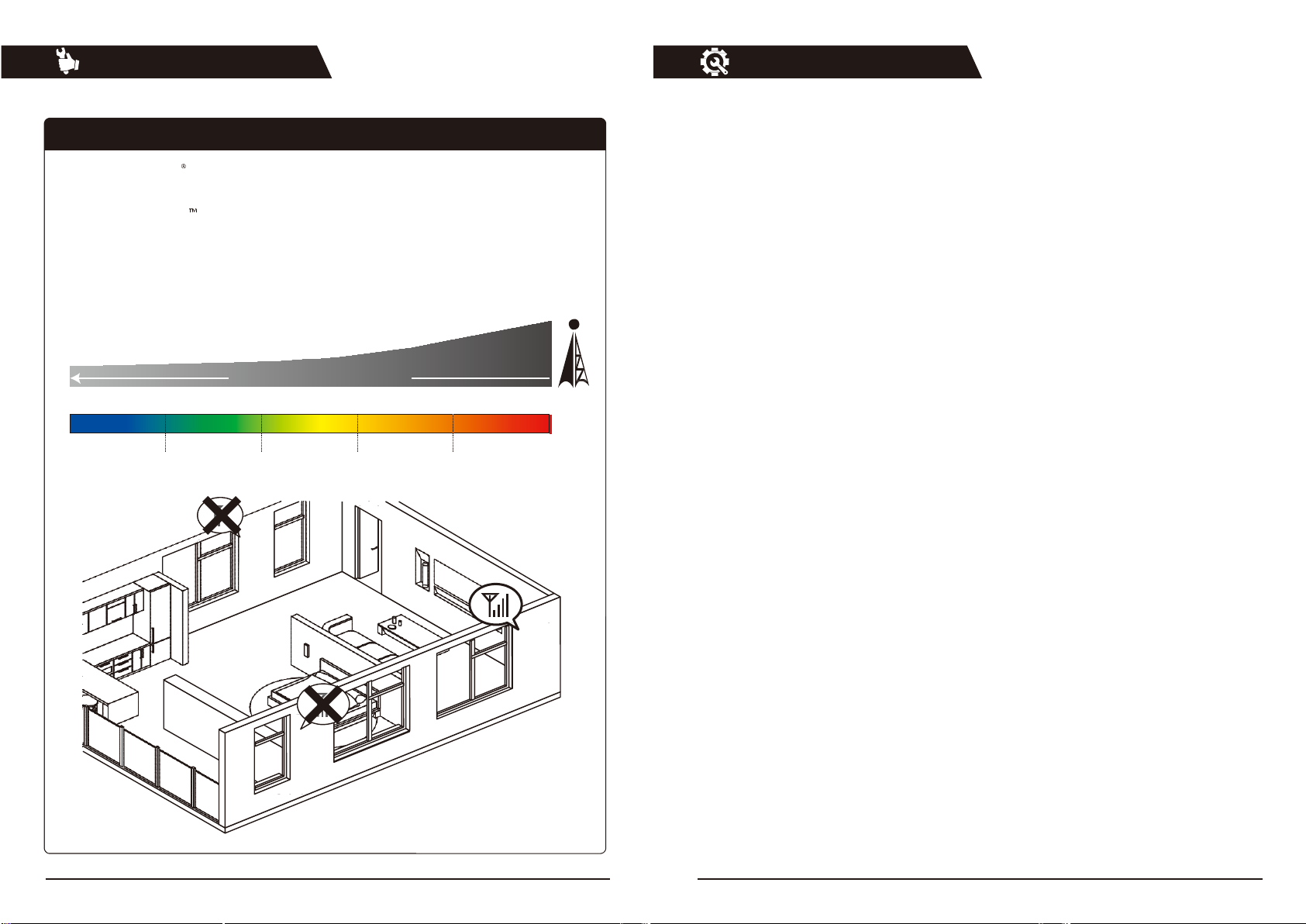
STEP 1. Find the Strongest Signal
1-1. Using an iPhone
Dial *3001#12345#*, then press Call.
1-2. Using an Android
Download the ‘Network Signal info’ from the Google Play store.
After installing, you will be able to view your dB strength.
1-3. Using a Meter
If you have a meter that detects and displays the current signal levels, you can use it.
Distance from Cell Tower
-100 -90 -80 -70 -60 -50
(dBm)
Troubleshooting
Installation Guide
Weak signal
Less weak signal
Good signal
Very good signal
Excellent signal
Instructions to fix
If you have a good voice signal and fast data speeds even though one or two of LEDs are solid red,
you may continue to use the Signal Booster as it is.
However, if one of the LED’s has flashing or solid red, your voice signal is weak and data speeds are low,
Then follow the troubleshooting steps below.
flashing
or solid red.
1. Unplug the Signal Booster’s power adapter.
2. Check if the outside antenna and inside antenna are located a minimum distance of 20 feet
from each other.
3. Plug the Signal Booster into a power source.
4. Check the LED on the Signal Booster. If one or two of the LEDs are still flashing or solid red, then try
moving the inside antenna further away from the outside antenna and repeat steps 1 through 3
to see if the additional distance resolves the problem.
5. If you have any difficulties with installation or troubleshooting the Signal Booster, please contact
our technical support team for assistance (Tel : 913-469-6699).
LED’s Off
1. If none of the LEDs on the Home 5000 Signal booster are lit, verify that the signal booster is connected
properly to the AC/DC power adapter cord and then verify that the power adapter is plugged into a live
AC outlet in the house.
2. Check if there is any damage in the power cable.
3. Check if there is any damage in the Signal Booster’s connector.
Page 9

16 9
HOME 5000 User Guide
HOME 5000 User Guide
STEP 1. Find the Strongest Signal
Note The stronger signal you receive from the base station, the better coverage you will have
inside your house/office.
-70dBm
If you have -70dBm outside signal, then you will have an excellent signal inside your house or office.
-90dBm
If you have -90dBm outside signal, then you will have a good signal inside your house & office.
700
850
1900
2100
700
850
1900
2100
LED
LED Indicators
Flashing Green
After the Signal Booster is powered on, flashing green will last for 20 seconds.
It means that the Signal Booster is being set up for optimal performance.
The Signal Booster will need a few minutes to adapt to the network environment and start boosting
the signal at the highest power.
The Signal Booster provides a real-time self-diagnosis, so in case of flashing or solid red, refer to the
Troubleshooting instructions on the next page.
Solid Green
This indicates that the Signal Booster has been installed and works properly.
Solid Orange
If one or more LEDs are solid orange, it means that the input signal from the nearby cell tower is between
-25dBm and -30dBm (very strong). In this event, we recommend that you reposition the outside antenna
to point in a different direction to weaken the signal. If the rest of the LEDs are green and you have a
strong signal and fast data speeds on your cell phone, then troubleshooting is not needed.
Flashing & Solid Red
If one or more of the LEDs is flashing or solid red, this indicates that the input signal from the nearby
cell tower is too strong.
After flashing red for 10 seconds the solid red will appear.
Signal Booster will stop amplifying signals of the frequency with a solid red indicator automatically
to prevent the Booster from any damage.
If the rest of LEDs are green and you have a strong signal and fast data speeds on your cell phone or
tablet, then troubleshooting is not needed.
Page 10
10 15
HOME 5000 User Guide
HOME 5000 User Guide
STEP 2. Install the Outside Antenna
The outside antenna is shaped like a triangle. This antenna must be mounted as high as possible on the
exterior of the house or office, but never higher than 10m above the ground. Mount the outside antenna on
the side of the house where you detected the strongest cell phone signal. The point of the antenna triangle
should be
pointed towards the location of the strongest cell phone signal (which should also be the direction
of the closest cell tower) and away
from the expected placement of the inside antenna.
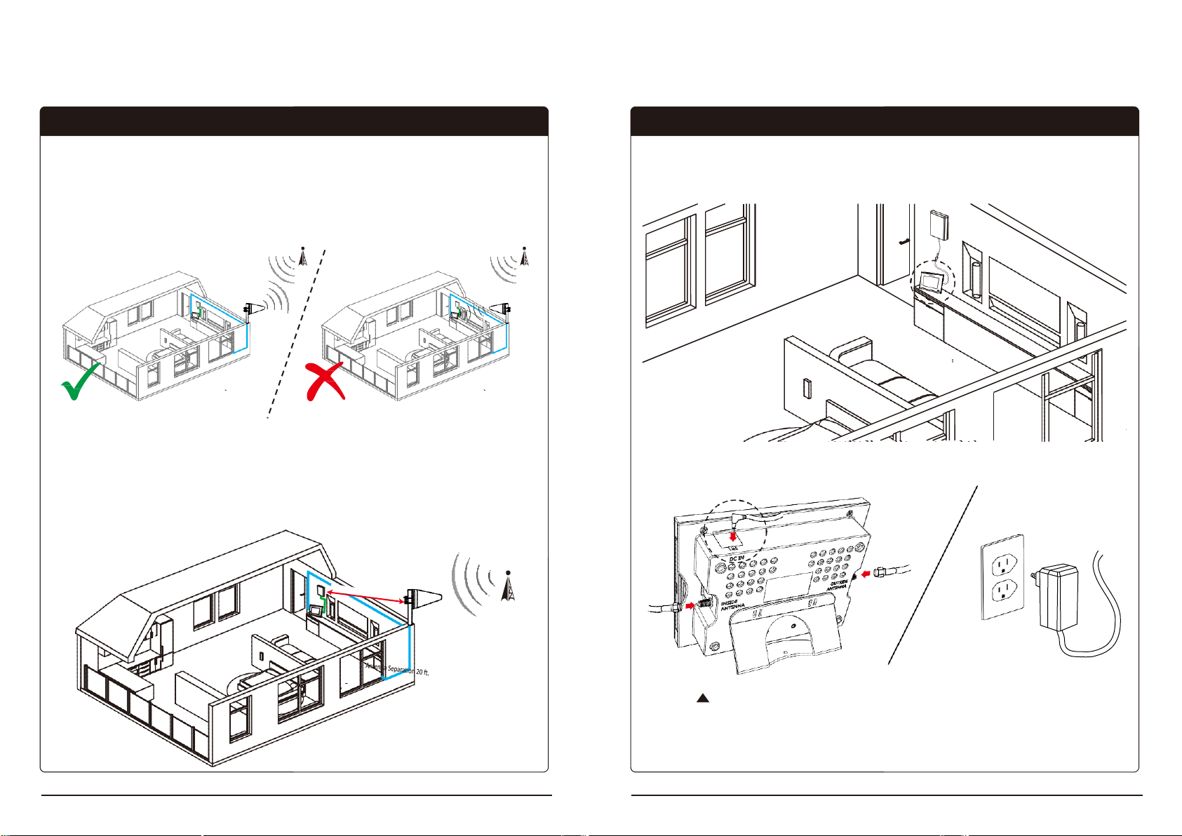
Separation Between Outside Antenna and Inside Antenna
For the best performance, the outside antenna and the inside antenna should be a minimum
distance of 20 ft. apart from each other. A bigger separation between outside antenna and
inside antenna will provide a stronger signal and better coverage.
Step 6. Install the Signal Booster
Choose a location for the signal booster, preferably away from excessive heat, direct sunlight,
moisture and free from high temperatures. Do not place the signal booster in an air-tight
enclosure. Attic installations may expose the booster to high heat.
Power
Signal Booster’s Back View
Connect the AC/DC power adaptor to the booster and plug into a power source.
The power LED will light, indicating that the signal booster is ready for use.
Page 11

14 11
HOME 5000 User Guide
HOME 5000 User Guide
Note
STEP 5. Install the Inside Antenna
Inside Panel Antenna is directional, so the signal will be distributed from its front side in one
direction. We would not recommend to install the Inside Antenna close to the floor.
Inside
Antenna
wall
Tap anchors
To Inside
Antenna
Cable (25 ft.)
Mount the Inside Antenna with the included screws and bracket as shown in the picture.
The Inside Antenna should be installed a minimum distance of 20 ft. from the outside antenna.
STEP 2. Install the Outside Antenna
Install the outside antenna in a location where you can receive the strongest signal according to
the instructions described in STEP 1.
Make sure outside antenna is installed with the point of the triangle facing toward the cell tower.
1 2
3
Page 12
12 13
HOME 5000 User Guide
HOME 5000 User Guide
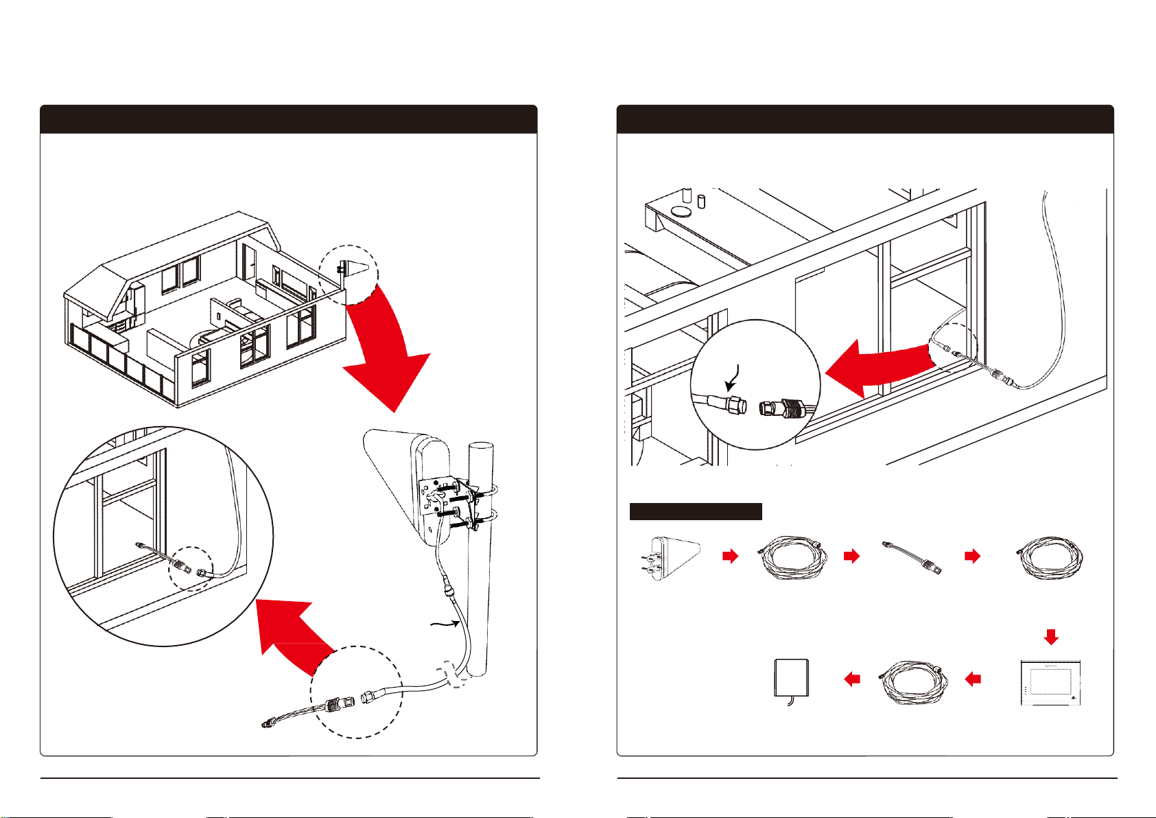
HOME 5000 Cable Line
STEP 4. Run the Cable to the Booster
Connect the cable from the booster to the window flat cable.
To Booster
Cable (20 ft.)
Outside
Antenna
40 ft. N-SMA
Coaxial Cable
1 ft. Window Flat
Cable
20 ft. SMA -SMA
Coaxial Cable
70
0
85
0
Inside
Antenna
25 ft. N-SMA
Coaxial Cable
Signal Booster
STEP 3. Run the Outside Antenna Cable
Connect the outside N-SMA cable with the yagi antenna.
Then, connect the window flat cable with the outside cable.
Outside Antenna
to 40 ft. cable
Page 13

Supplier's Declaration of Conformity
47 CFR § 2.1077 Compliance Information
Unique Identifier: HOME 5000
Responsible Party – U.S. Contact Information
GSTeletech,Inc.
8206 Marshall Drive,
Lenexa, Kansas 66214
Contact point
Charles You
chyu@gsteletechinc.com
Office : 1-913-469-6699
Fax : 1-913-661-0163
FCC Compliance Statement (e.g., products subject to Part 15)
This device complies with Part 15 of the FCC Rules. Operation is subject to the following two
conditions: (1) This device may not cause harmful interference, and (2) this device must accept any
interference received, including interference that may cause undesired operation.
 Loading...