

Page 1

Version
0.1
Date
May 11, 2018
Page
1/ 42
Title
USER MANUAL
Prepared by
Reviewed by
Approved by
USER MANUAL
EZD-LICPA23
EZS-LICPA30
May 11, 2018
GS Instech Co., Ltd.
© 2018 GS Instech Co., Ltd. All rights reserved.
1
Page 2
Version
0.1
Date
May 11, 2018
Page
2/ 42
Title
USER MANUAL
Prepared by
Reviewed by
Approved by
DATE
NAMES
DESCRIPTIONS
VERSION
REMARK
May 11, 2018
H.J.CHOI
Original Draft
0.1
[CHANGE RECORD]
© 2018 GS Instech Co., Ltd. All rights reserved.
2
Page 3
Version
0.1
Date
May 11, 2018
Page
3/ 42
Title
USER MANUAL
Prepared by
Reviewed by
Approved by
CHAPTER’s INDEX
[TABLE OF CONTENTS]
1. GENERAL ............................................................................. 7
1.1. Purpose ............................................................................................. 7
1.2. Copyright ........................................................................................... 7
1.3. FCC Warning Statements .......................................................................... 8
2. INTRODUCTION .................................................................... 11
2.1. System Overview ................................................................................. 11
2.2. Main Features .................................................................................... 12
3. SYSTEM DESIGN FOR EZD-LICPA23 (DONOR UNIT) ............................... 13
3.1. Exterior View ...................................................................................... 13
3.2. Interior View ...................................................................................... 14
3.3. External Interface ................................................................................. 15
3.4. FCC Statement ..................................................................................... 16
4. SYSTEM DESIGN FOR EZS-LICPA30 (SERVICE UNIT) ............................... 17
4.1. Exterior View ..................................................................................... 17
4.2. Interior View ...................................................................................... 18
4.3. External Interface ................................................................................ 19
4.4. FCC Statement .................................................................................... 20
© 2018 GS Instech Co., Ltd. All rights reserved.
3
Page 4
Version
0.1
Date
May 11, 2018
Page
4/ 42
Title
USER MANUAL
Prepared by
Reviewed by
Approved by
5. SYSTEM SPECIFICATION ............................................................ 21
5.1. RF Performance................................................................................... 21
5.2. Frequency Information ........................................................................... 23
5.2.1. 700MHz ..................................................................................................................................................................................................... 23
5.2.2. 800/850MHz ............................................................................................................................................................................................ 24
5.2.3. 1900MHz ................................................................................................................................................................................................... 25
5.2.4. 2100MHz ................................................................................................................................................................................................... 26
5.3. Configuration & Mechanical Specification ..................................................... 27
6. SYSTEM BLOCK CONFIGURATION ................................................. 28
6.1. Block Diagram .................................................................................... 28
7. GUI OVERVIEW ..................................................................... 30
7.1. Configuration the Laptop to Connect to the Repeater .......................................... 30
7.2. Login-In Screen .................................................................................... 31
7.3. Main Screen ...................................................................................... 32
7.4. RF Status .......................................................................................... 33
7.5. RF Configuration .................................................................................. 34
7.6. Band Selection .................................................................................... 35
8. SYSTEM INSTALLATION ............................................................ 36
8.1. Warnings and Hazards ............................................................................ 37
8.1.1. Electric Shock ........................................................................................................................................................................................... 37
8.1.2. Exposure to RF ......................................................................................................................................................................................... 37
8.2. Service Man Installation Guide ................................................................. 38
8.2.1. Wall Mount Installation ......................................................................................................................................................................... 38
© 2018 GS Instech Co., Ltd. All rights reserved.
4
Page 5
Version
0.1
Date
May 11, 2018
Page
5/ 42
Title
USER MANUAL
Prepared by
Reviewed by
Approved by
FIGURE’s INDEX
TABLE’s INDEX
8.3. Cable Connection ................................................................................. 40
8.3.1. AC Power cable connection .................................................................................................................................................................. 40
8.3.2. Local Maintenance Connection ........................................................................................................................................................... 41
8.3.3. Grounding cable Connection ............................................................................................................................................................... 41
FIGURE 1.FCC/ UL CERTIFICATION STATEMENT ......................................................................................................................................................... 8
FIGURE 2.EZ-DAS APPLICATION CONFIGURATIONS ............................................................................................................................................... 11
FIGURE 3. EZD-LICPA23 EXTERIOR VIEW .................................................................................................................................................................. 13
FIGURE 4. EZD-LICPA23 INTERIOR VIEW .................................................................................................................................................................. 14
FIGURE 5. EZD-LICPA23 EXTERNAL INTERFACE ....................................................................................................................................................... 15
FIGURE 6. EZD-LICPA23 UNIT FCC STATEMENT ....................................................................................................................................................... 16
FIGURE 6. EZS-LICPA30 EXTERIOR VIEW ................................................................................................................................................................... 17
FIGURE 7. EZS-LICPA30 INTERIOR VIEW ................................................................................................................................................................... 18
FIGURE 9. EZS-LICPA30 EXTERNAL INTERFACE........................................................................................................................................................ 19
FIGURE 10. EZS-LICPA30 UNIT FCC STATEMENT ..................................................................................................................................................... 20
FIGURE 11. EZD-LICPA23 BLOCK DIAGRAM CONFIGURATION ............................................................................................................................ 28
FIGURE 12. EZS-LICPA30 BLOCK DIAGRAM CONFIGURATION ............................................................................................................................. 29
FIGURE 13. THE WAY TO FIX THE BRACKET ON THE POLE (NORMAL TYPE) .................................................................................................... 38
FIGURE 14. THE WAY TO FIX FIRMLY THE SYSTEM FOR POLE MOUNTING ...................................................................................................... 39
TABLE 1. EZD-LICPA23 UNIT CONFIGURATION ........................................................................................................................................................ 14
TABLE 2. EZD-LICPA23 EXTERNAL INTERFACE DESCRIPTION ............................................................................................................................... 15
TABLE 3. EZS-LICPA30 UNIT CONFIGURATION ......................................................................................................................................................... 18
TABLE 4. EZS-LICPA30 EXTERNAL INTERFACE DESCRIPTION ................................................................................................................................ 19
TABLE 5. EZ-DAS RF PERFORMANCE DESCRIPTION ............................................................................................................................................... 22
TABLE 6. EZ-DAS 700MHZ OPERATING FREQUENCY INFORMATION ................................................................................................................. 23
TABLE 7. EZ-DAS 800/850MHZ OPERATING FREQUENCY INFORMATION FOR CDMA .................................................................................. 24
TABLE 8. EZ-DAS 800/850MHZ OPERATING FREQUENCY INFORMATION FOR LTE ........................................................................................ 24
TABLE 9. EZ-DAS 1900MHZ OPERATING FREQUENCY INFORMATION FOR CDMA ......................................................................................... 25
TABLE 10. EZ-DAS 1900MHZ OPERATING FREQUENCY INFORMATION FOR LTE ............................................................................................ 25
© 2018 GS Instech Co., Ltd. All rights reserved.
5
Page 6

Version
0.1
Date
May 11, 2018
Page
6/ 42
Title
USER MANUAL
Prepared by
Reviewed by
Approved by
TABLE 11. EZ-DAS 2100MHZ OPERATING FREQUENCY INFORMATION ............................................................................................................ 26
TABLE 12. EZ-DAS CONFIGURATION & MECHANICAL SPECIFICATION............................................................................................................... 27
TABLE 13. EZ-DAS INSTALLATION ACCESSORIES...................................................................................................................................................... 36
© 2018 GS Instech Co., Ltd. All rights reserved.
6
Page 7

Version
0.1
Date
May 11, 2018
Page
7/ 42
Title
USER MANUAL
Prepared by
Reviewed by
Approved by
1. General
1.1. Purpose
This document introduces features, specifications, structures and operation guideline for
the EZD-LICPA23/ EZS-LICPA30.
1.2. Copyright
All text and image in this document are subject to the copyright of GS Instech Co., Ltd.
This document may not be reproduced, distributed, or modified without the written permission of
GS Instech Co., Ltd.
© 2018 GS Instech Co., Ltd. All rights reserved.
7
Page 8
Version
0.1
Date
May 11, 2018
Page
8/ 42
Title
USER MANUAL
Prepared by
Reviewed by
Approved by
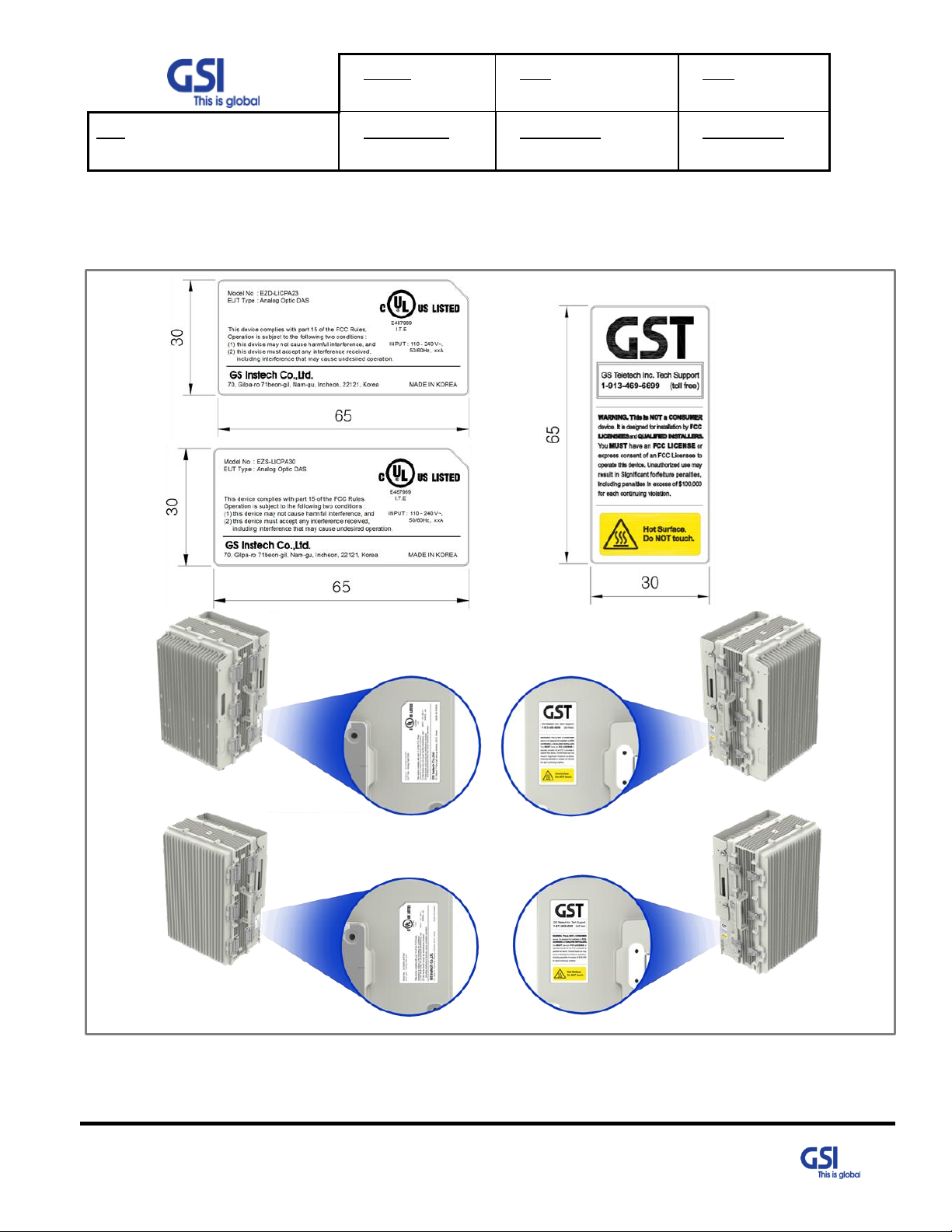
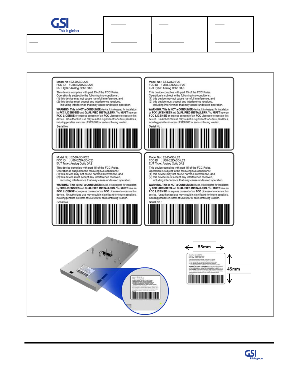
1.3. FCC Warning Statements
FCC Warning Statement for system is follows. Must attach the label under manufacturing.
© 2018 GS Instech Co., Ltd. All rights reserved.
Figure 1.FCC/ UL Certification Statement
8
Page 9

Version
0.1
Date
May 11, 2018
Page
9/ 42
Title
USER MANUAL
Prepared by
Reviewed by
Approved by
FCC Part 15.105 statement (Class A)
This equipment has been tested and found to comply with the limits for a Class A digital device, pursuant to part 15 of
the FCC Rules. These limits are designed to provide reasonable protection against harmful interference when the
equipment is operated in a commercial environment. This equipment generates, uses, and can radiate radio frequency
energy and, if not installed and used in accordance with the instruction manual, may cause harmful interference to
radio communications. Operation of this equipment in a residential area is likely to cause harmful interference in which
case the user will be required to correct the interference at his own expense.
FCC Part 15.21 statement
Any changes or modifications not expressly approved by the party responsible for compliance
could void the user's authority to operate this equipment.
Home/ personal use are prohibited
Use of unauthorized antennas, cables, and/or coupling devices not conforming with ERP/EIRP
and/or indoor‐only restrictions is prohibited
9
© 2018 GS Instech Co., Ltd. All rights reserved.
Page 10
Version
0.1
Date
May 11, 2018
Page
10/ 42
Title
USER MANUAL
Prepared by
Reviewed by
Approved by
Type
Model name(s)
HAAT (m)
Antenna again
SU
EZ-DASS-L37
11 337.60
3dBi
EZ-DASS-L30
25 313.42
3dBi
EZ-DASS-IC37
4 293.78
3dBi
EZ-DASS-IC30
9 534.59
3dBi
EZ-DASS-P37
2 749.43
7dBi
EZ-DASS-P30
6 135.58
7dBi
EZ-DASS-A39
5 725.41
7dBi
EZ-DASS-A32
13 003.80
7dBi
DU
EZ-DASD-L23
14 408.20
15dBi
EZ-DASD-IC23
5 360.99
15dBi
EZ-DASD-P23
3 799.80
18dBi
EZ-DASD-A23
10 151.20
18dBi
RF Radiation Exposure
This equipment complies with RF radiation exposure limits set forth for an uncontrolled environment.
This transmitter must not be co-located or operating in conjunction with any other antenna or transmitter.
RF exposure will be addressed at time of installation and the use of higher gain antennas may require larger
separation distances.
Antenna installation
Antennas must be installed in accordance with FCC 27.50, 24.
The height of the antenna above average terrain (HAAT) must not exceed limit in the following table.
WARNING. THIS is NOT a CONSUMER device. It is designed for installation by FCC LICENSEES and QUALIFIED
INSTALLERS. You MUST have an FCC LICENSE or express consent of an FCC Licenses to operate this device.
Unauthorized use may result in significant forfeiture penalties, including penalties in excess of $100,000
for each continuing violation.
© 2018 GS Instech Co., Ltd. All rights reserved.
10
Page 11
Version
0.1
Date
May 11, 2018
Page
11/ 42
Title
USER MANUAL
Prepared by
Reviewed by
Approved by
2. Introduction
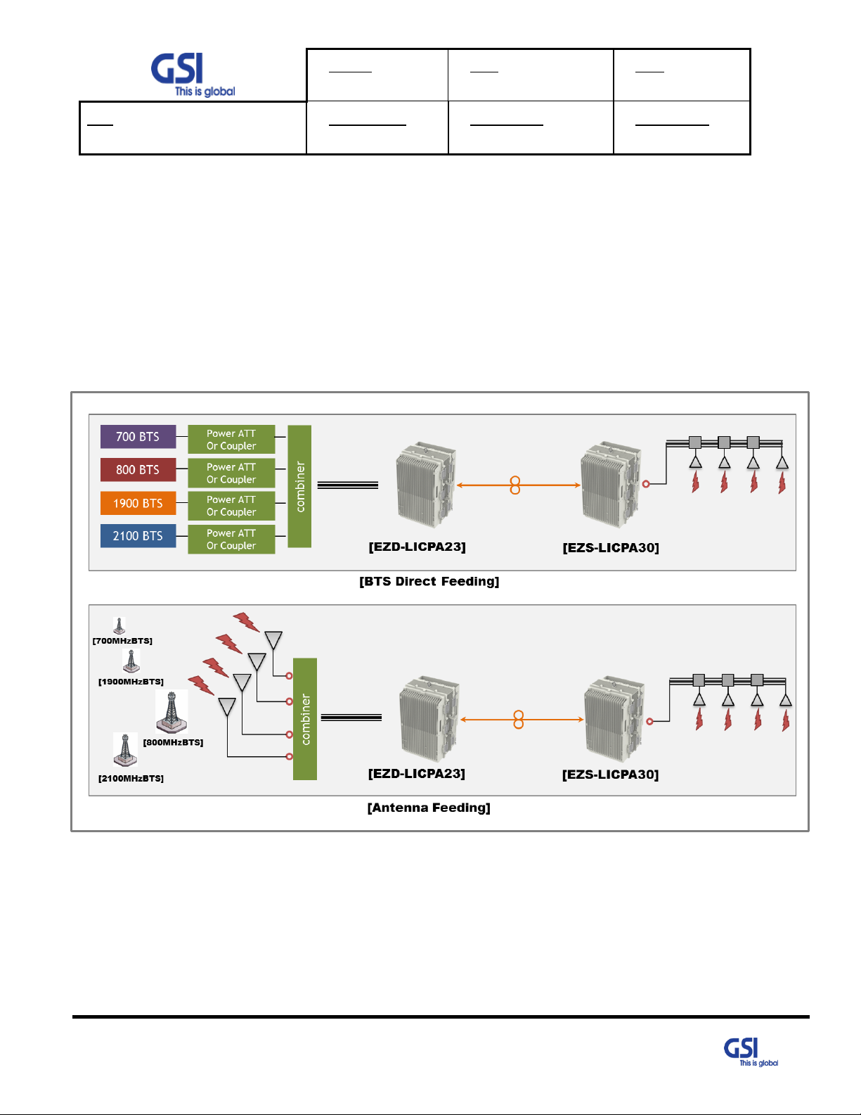
2.1. System Overview
EZ-DAS is designed to improve coverage and capacity of Commercial Quad Band.
Either feeding Carrier BTS signal directly or receiving signal via antenna, it provides coverage
Building in RF shadow.
© 2018 GS Instech Co., Ltd. All rights reserved.
Figure 2.EZ-DAS Application Configurations
11
Page 12

Version
0.1
Date
May 11, 2018
Page
12/ 42
Title
USER MANUAL
Prepared by
Reviewed by
Approved by
2.2. Main Features
● All-in One Donor Unit
- Compose several units such as Optic Transceiver, NMS, PSU, BDA, Cavity Filter etc.
- Convenient to install in Middle Size Building with proper cost of one set
● Support the BTS or Antenna Feeding Solution
- Either feeding Carrier BTS Signal directly or receiving signal via Antenna
- With built-in BDA(Bi-Directional Amplifier) function, it is possible to use under Antenna feeding
condition
● Choose the Filtering Methods accord to the operating condition
- For Neutral Host installations, able to support the Full Band Filtering
● Improving Service Quality under Multi-Carriers Area
- Up to 6 Non-Contiguous block and gain per block based on Downlink Input Topologies
- Dealing with Near-far & Uplink Noise Floor Rise
● Topologies
- 1:4 Branches between Donor Unit and Service Unit.
- 3 Daisy Chain is possible with Daisy Chain Optic Unit.
● Supporting Technologies
- CDMA, LTE
● Supporting Frequencies
- Commercial Quad band (700M, 800+850M, 1900M, 2100M)
● Supporting Output Power
- Composite 4W with EZ-DASS-LICPA 30 (1W per Band)
- Composite 20W with EZ-DASS-LICPA 37 (5W per Band)
● Functions
- Support AGC, ALC, AGA with LLA(Low Limit ALC), ASD
● FCC Part 22, 24,27,90 & Part 15B class A
© 2018 GS Instech Co., Ltd. All rights reserved.
12
Page 13
Version
0.1
Date
May 11, 2018
Page
13/ 42
Title
USER MANUAL
Prepared by
Reviewed by
Approved by
3. System Design for EZD-LICPA23 (Donor Unit)
3.1. Exterior View
© 2018 GS Instech Co., Ltd. All rights reserved.
Figure 3. EZD-LICPA23 Exterior View
13
Page 14

Version
0.1
Date
May 11, 2018
Page
14/ 42
Title
USER MANUAL
Prepared by
Reviewed by
Approved by
No
Name
Remark
1
EZ-DASD-IC23
800/850MHz RF Digital Filter Unit
2
EZ-DASD-P23
1900MHz RF Digital Filter Unit
3
EZ-DASD-L23
700MHz RF Digital Filter Unit
4
EZ-DASD-A23
2100MHz RF Digital Filter Unit
5
Cavity Filter
Quadplexer for 800/850M & 1900M/ 700M+2100M Band Combiner
6
Cavity Filter
Quadplexer for 700M & 2100M
7
PSU
AC Input Voltage: 110VAC~240VAC(60Hz)/ DC Output Voltage: +6V
8
DOU
Donor Optic Unit (4Port)
9
RCDU-5W
5Way RF Channel Distribute Unit
10
SNMP Board
Apply for Web-UI/ Communicate with Service Unit
3.2. Interior View
Figure 4. EZD-LICPA23 Interior View
Table 1. EZD-LICPA23 Unit Configuration
© 2018 GS Instech Co., Ltd. All rights reserved.
14
Page 15

Version
0.1
Date
May 11, 2018
Page
15/ 42
Title
USER MANUAL
Prepared by
Reviewed by
Approved by
No
NAMES
DESCRIPTION
SPECIFICATION
1
ANT
Feeding Downlink Signal
/ Transmit Uplink Output
4.3-10 Din Connector
2
AC IN
AC Input Outlet
MS3102A 22-2
3
OPTIC0~3
Insert the optic cable to Service Unit
Metal Cable Gland
4
EDU RF DL
Receive a Downlink RF Signal from EDU (Wire only)
SMA(F)
5
EDU RF UL
Transmit a uplink RF Signal to EDU (Wire only)
SMA(F)
6
LAN
Communicate a data between MDU & EDU or Server
RJ-45
7
LED
System Total Alarm Indication
General Performance
8
Vent-Core
Maintain Humidity & Temp Inside
IP66
3.3. External Interface
Figure 5. EZD-LICPA23 External Interface
Table 2. EZD-LICPA23 External Interface Description
© 2018 GS Instech Co., Ltd. All rights reserved.
15
Page 16
Version
0.1
Date
May 11, 2018
Page
16/ 42
Title
USER MANUAL
Prepared by
Reviewed by
Approved by
3.4. FCC Statement
© 2018 GS Instech Co., Ltd. All rights reserved.
Figure 6. EZD-LICPA23 UNIT FCC Statement
16
Page 17

Version
0.1
Date
May 11, 2018
Page
17/ 42
Title
USER MANUAL
Prepared by
Reviewed by
Approved by
4. System Design for EZS-LICPA30 (Service Unit)
4.1. Exterior View
© 2018 GS Instech Co., Ltd. All rights reserved.
Figure 7. EZS-LICPA30 Exterior View
17
Page 18

Version
0.1
Date
May 11, 2018
Page
18/ 42
Title
USER MANUAL
Prepared by
Reviewed by
Approved by
No
Name
Remark
1
EZ-DASS-IC30
800/850MHz RF Power Amp Unit
2
EZ-DASS-P30
1900MHz RF Power Amp Unit
3
EZ-DASS-L30
700MHz RF Power Amp Unit
4
EZ-DASS-A32
2100MHz RF Power Amp Unit
5
Cavity Filter
Quadplexer for 800/850M & 1900M/ 700M+2100M Band Combiner
6
Cavity Filter
Quadplexer for 700M & 2100M
7
PSU
AC Input Voltage: 110VAC~240VAC(60Hz)/ DC Output Voltage: +6V/ +29V
8
SOU
Service Optic Unit
9
RCDU-4W
4Way RF Channel Distribute Unit
10
NMS Board
Apply for GUI/ Communicate with Donor Unit
11
DCO
Daisy Chain Optic Unit/ For SU Cascade Application
4.2. Interior View
Figure 8. EZS-LICPA30 Interior View
Table 3. EZS-LICPA30 Unit Configuration
© 2018 GS Instech Co., Ltd. All rights reserved.
18
Page 19

Version
0.1
Date
May 11, 2018
Page
19/ 42
Title
USER MANUAL
Prepared by
Reviewed by
Approved by
No
NAMES
DESCRIPTION
SPECIFICATION
1
ANT
Feeding Uplink Signal
/ Transmit Downlink Output
4.3-10 Din Connector
2
AC IN
AC Input Outlet
MS3102A 22-2
3
OPTIC0
Insert the optic cable to Donor Unit
Metal Cable Gland
4
OPTIC1
Insert the optic cable to Next SU for Daisy Chain
Metal Cable Gland
5
LED
System Total Alarm Indication
General Performance
6
Vent-Core
Maintain Humidity & Temp Inside
IP66
4.3. External Interface
Figure 9. EZS-LICPA30 External Interface
© 2018 GS Instech Co., Ltd. All rights reserved.
Table 4. EZS-LICPA30 External Interface Description
19
Page 20

Version
0.1
Date
May 11, 2018
Page
20/ 42
Title
USER MANUAL
Prepared by
Reviewed by
Approved by
4.4. FCC Statement
© 2018 GS Instech Co., Ltd. All rights reserved.
Figure 10. EZS-LICPA30 UNIT FCC Statement
20
Page 21

Version
0.1
Date
May 11, 2018
Page
21/ 42
Title
USER MANUAL
Prepared by
Reviewed by
Approved by
Parameter
Down Link
Up Link
Remark
Frequency Range
728MHz~756MHz
698MHz~716MHz/ 777MHz~787MHz
700MHz
862MHz~894MHz
817MHz~849MHz
800/850MHz
1930MHz~1995MHz
1850MHz~1915MHz
1900MHz
2110MHz~2180MHz
1710MHz~1755MHz
2100MHz
Input Range
-60dBm ~ -30dBm/ Total
-67dBm
Per Band
Output Power
+30dBm with EZS-LICPA30
+23dBm(0.2W)
With EZD-LICPA23
700M
+30dBm with EZS-LICPA30
800/850MHz
+30dBm with EZS-LICPA30
1900M
+32dBm with EZS-LICPA30
2100M
Channel Capacity
【CDMA】 15MHz max/ 1.25MHz Step
【LTE】 5M, 10M, 20M
Gain
Range
50dB ~ 90dB with EZS-LICPA30
ALC, AGC
Included
Adjust Step
1dB
Accuracy
±1dB
Ripple
4dB p-p
Roll off
> 50dBc @ Channel OBW ±1MHz
Rho
≥ 0.912 (Rho)
For CDMA
EVM
< 4% for 256QAM
< 4% for 64QAM
For LTE
5. System Specification
5.1. RF Performance
© 2018 GS Instech Co., Ltd. All rights reserved.
21
Page 22
Version
0.1
Date
May 11, 2018
Page
22/ 42
Title
USER MANUAL
Prepared by
Reviewed by
Approved by
Parameter
Down Link
Up Link
Remark
Frequency Error
< 0.05ppm
System Delay
< 5us
Exclude Fiber
Optic Delay
Noise Figure
Less than 6dB @ Min & Max Gain
Only UL
VSWR
< 1.5 : 1
OB Unwanted
Emission
<-5.5dBm @50KHz ≤ ∆f < 5.05MHz (RBW: 100KHz)
For LTE
<-12.5dBm @5.05MHz ≤ ∆f < 10.05MHz (RBW: 100KHz)
<-13dBm @10.5MHz ≤ ∆f < 15MHz (RBW: 1MHz)
ACLR
> 45dBc @ ±5MHz, ±10MHz, ±20MHz, ±40MHz
For LTE
Spurious Emission
For CDMA
885 kHz
-45dBc with a 30KHz RBW
1.98 MHz
P
out
> 33dBm; -55dBc with a 30KHz RBW
28dBm P
out
<33dBm; -22dBm with a 30KHz RBW
2.25 MHz
-13dBm with a 30KHz RBW
4.0 MHz
-13dBm / 1 kHz: 9 kHz < f < 150 kHz
ITU
category A
-13dBm / 10 kHz: 150 kHz < f < 30 MHz
-13dBm/100 kHz: 30 MHz < f < 1 GHz
-13dBm / 1 MHz: 1 GHz < f < 12.75 GHz
© 2018 GS Instech Co., Ltd. All rights reserved.
Table 5. EZ-DAS RF Performance Description
22
Page 23
Version
0.1
Date
May 11, 2018
Page
23/ 42
Title
USER MANUAL
Prepared by
Reviewed by
Approved by
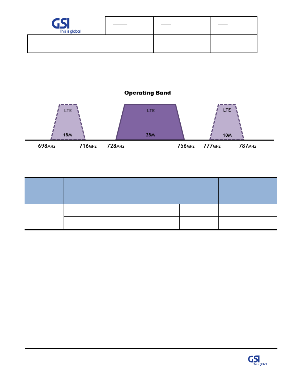
Block
Transmit frequency band (MHz)
Bandwidth
UL / DL
Uplink
Downlink
LTE 10M
698
716
728
746
18 (Lower C)
777
787
746
756
10 (Upper C)
5.2. Frequency Information
5.2.1. 700MHz
[LTE]
© 2018 GS Instech Co., Ltd. All rights reserved.
Table 6. EZ-DAS 700MHz Operating Frequency Information
23
Page 24
Version
0.1
Date
May 11, 2018
Page
24/ 42
Title
USER MANUAL
Prepared by
Reviewed by
Approved by
Block
Transmit frequency band (MHz)
Bandwidth
UL / DL
Uplink
Downlink
A1
824
835
869
880
11
B1
835
845
880
890
10
A2
845
846.5
890
891.5
1.5
B2
846.5
849
891.5
894
2.5
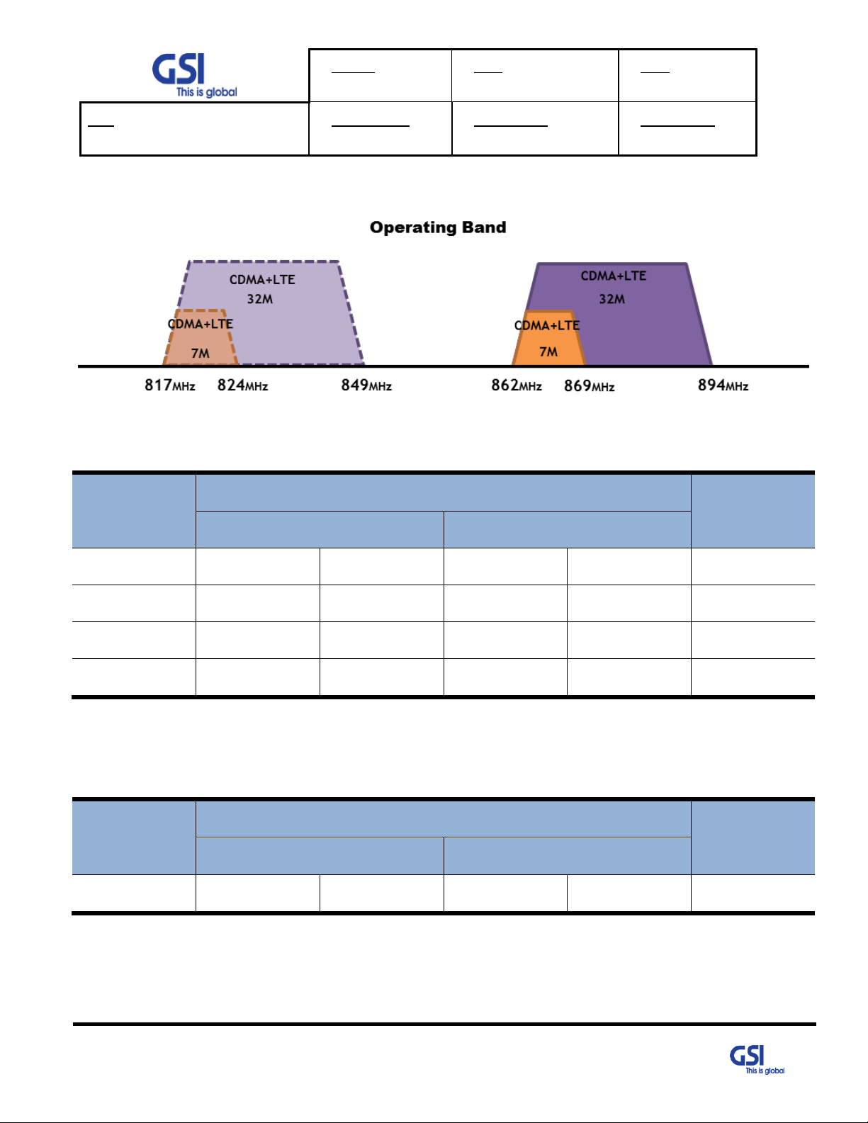
Block
Transmit frequency band (MHz)
Bandwidth
UL / DL
Uplink
Downlink
LTE 5M
817
849
862
894
32
5.2.2. 800/850MHz
[CDMA]
[LTE]
Table 7. EZ-DAS 800/850MHz Operating Frequency Information for CDMA
© 2018 GS Instech Co., Ltd. All rights reserved.
Table 8. EZ-DAS 800/850MHz Operating Frequency Information for LTE
24
Page 25
Version
0.1
Date
May 11, 2018
Page
25/ 42
Title
USER MANUAL
Prepared by
Reviewed by
Approved by
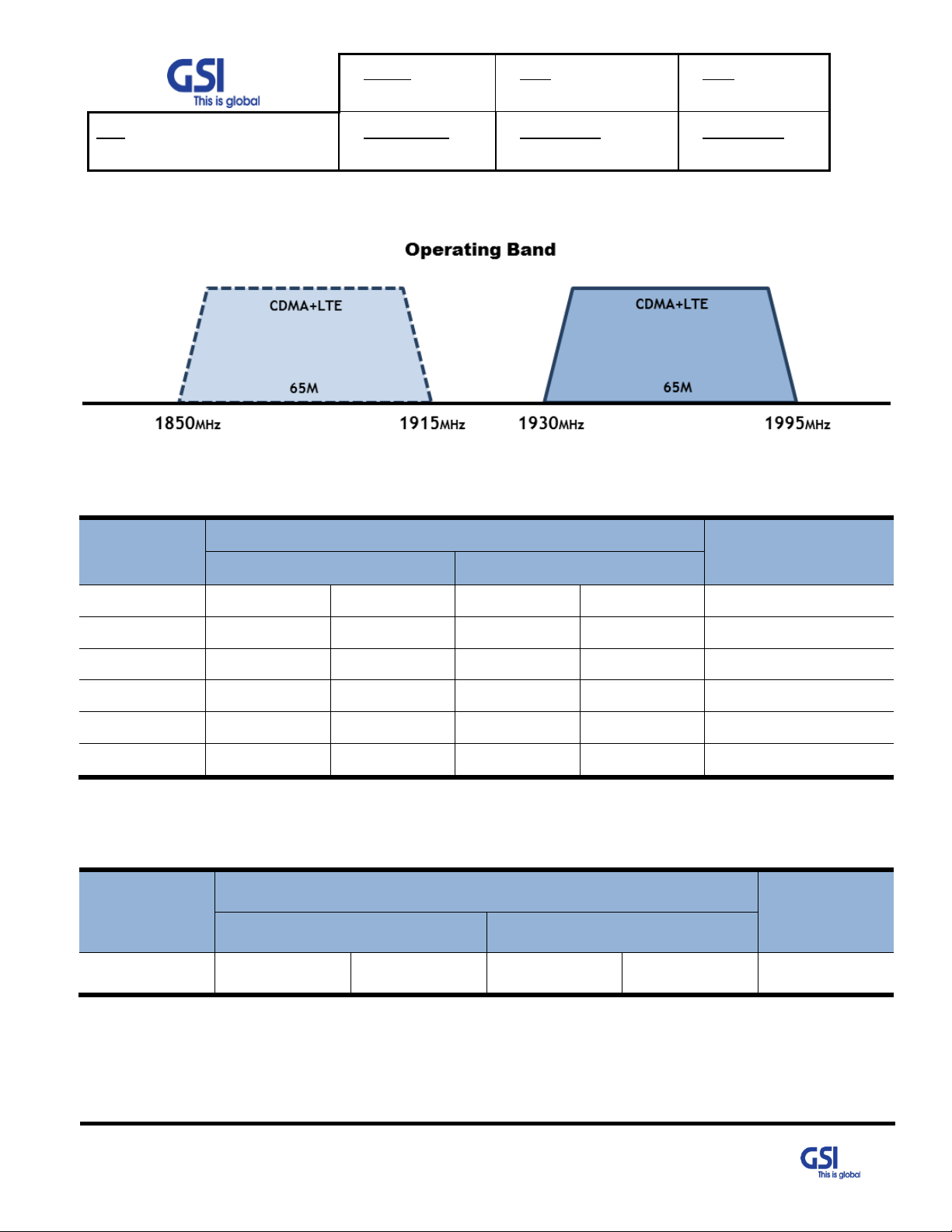
Block
Transmit frequency band (MHz)
Bandwidth
UL / DL
Uplink
Downlink
A
1850
1865
1930
1945
15
D
1865
1870
1945
1950
5
B
1870
1885
1950
1965
15
E
1885
1890
1965
1970
5
F
1890
1895
1970
1975
5
C
1895
1910
1975
1990
15
Block
Transmit frequency band (MHz)
Bandwidth
UL / DL
Uplink
Downlink
LTE 20M
1850
1915
1930
1995
65
5.2.3. 1900MHz
[CDMA]
[LTE]
Table 9. EZ-DAS 1900MHz Operating Frequency Information for CDMA
© 2018 GS Instech Co., Ltd. All rights reserved.
Table 10. EZ-DAS 1900MHz Operating Frequency Information for LTE
25
Page 26
Version
0.1
Date
May 11, 2018
Page
26/ 42
Title
USER MANUAL
Prepared by
Reviewed by
Approved by
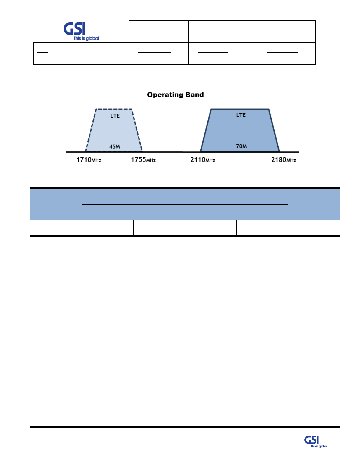
Block
Transmit frequency band (MHz)
Bandwidth
UL / DL
Downlink
Uplink
LTE 10M
2110
2180
1710
1755
45M/ 70M
5.2.4. 2100MHz
[LTE]
Table 11. EZ-DAS 2100MHz Operating Frequency Information
© 2018 GS Instech Co., Ltd. All rights reserved.
26
Page 27

Version
0.1
Date
May 11, 2018
Page
27/ 42
Title
USER MANUAL
Prepared by
Reviewed by
Approved by
Parameter
Specification
Remark
Donor/ Service
Antenna Filter
QUADPLEXER+BAND COMBINER
One port In/Output
Power Supply
AC Input Voltage: 110VAC~240VAC(60Hz)
Free Voltage
DC Output Voltage: +6V
EZD-LICPA23
DC Output Voltage: +6V/ +29V
EZS-LICPA30
Operation Temperature
-10°C~+50°C (100%RH)
Storage Temperature
-10°C~+80°C (5~95%RH)
Connectors
Antenna: 4.3-10 DIN Female
EZD-LICPA23
EZS-LICPA30
AC: MS-3102A 22-2
Optic Connection: Metal Cable Gland
EDU Connection: SMA Female(RF)/ MS3102A18-8(DATA)
EZD-LICPA23
Cable
1/2" Plenum-Rated Air-Dielectric Coaxial Cable
Size
13.78" x 21.6" x 12.2" without Bracket
EZD-LICPA23
13.78" x 21.6" x 10.3" without Bracket
EZS-LICPA30
Weigh
Less than 42kg (92.5lb) without Bracket
EZD-LICPA23
Less than 40kg (88.1lb) without Bracket
EZS-LICPA30
Power Consumption
Less than 200W
EZD-LICPA23
Less than 250W
EZS-LICPA30
Environment
IP54
MTBF
100,000 hours or higher
Grounding
nonferrous metal and anchoring point on bottom side
For RF and power cabling
Mount Application
Wall Mount
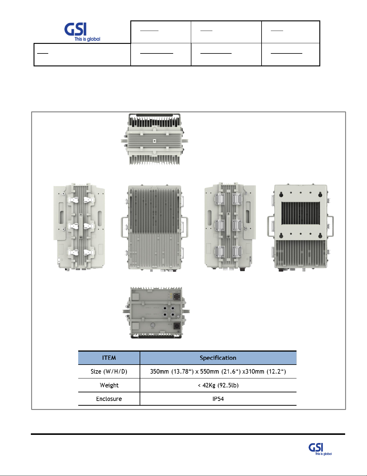
5.3. Configuration & Mechanical Specification
Table 12. EZ-DAS Configuration & Mechanical Specification
© 2018 GS Instech Co., Ltd. All rights reserved.
27
Page 28
Version
0.1
Date
May 11, 2018
Page
28/ 42
Title
USER MANUAL
Prepared by
Reviewed by
Approved by
6. System Block Configuration
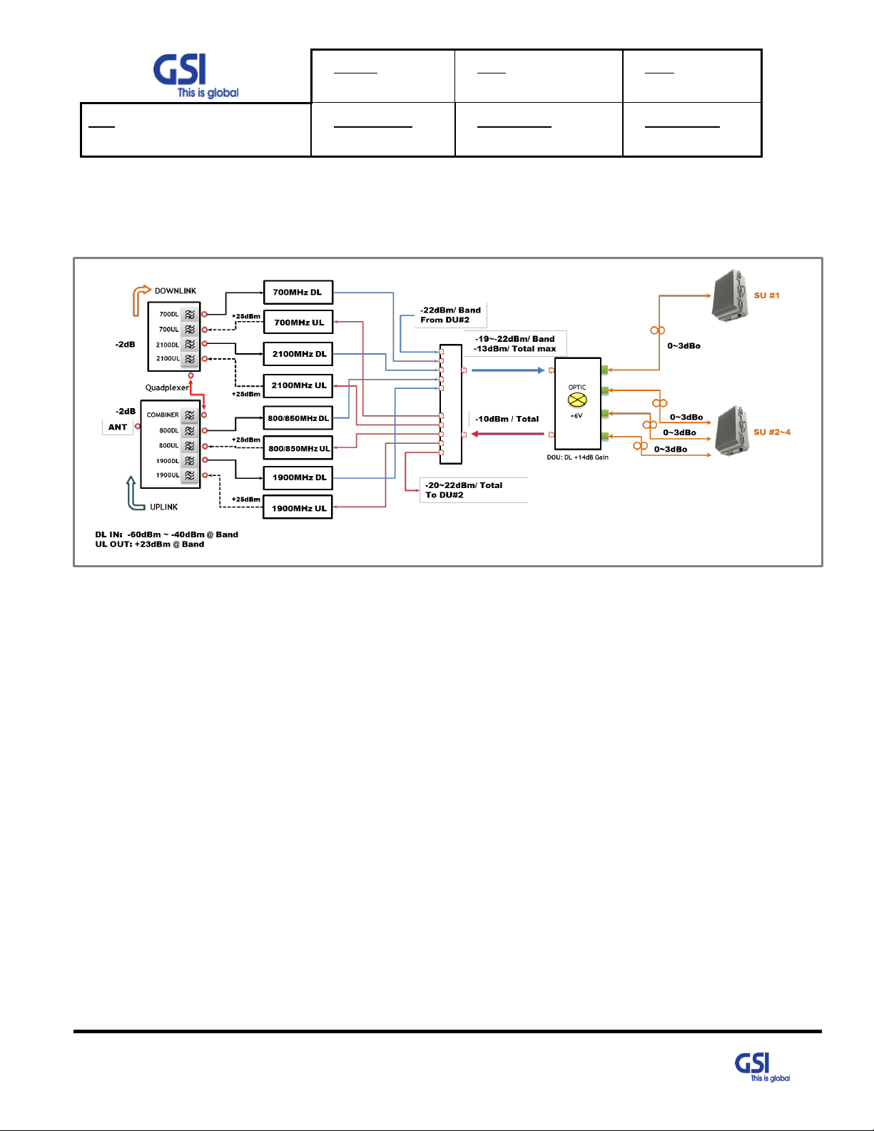
6.1. Block Diagram
Figure 11. EZD-LICPA23 Block Diagram Configuration
The repeater improves service in the commercial Quad-Band.
User may select frequency band according to the site peculiarities.
After receiving a weak signal from Donor antenna or BTS directly, the EZD-LICPA23 sends downlink signal to EZS-
LICPA30 using DOU (Donor Optic Unit).
DOU supports the translation of RF signal to Optic signal for connecting EZS-LICPA30 through
the fiber optic cable. And then Uplink Signal that received from EZS-LICPA30 amplify,
is send to the Base station via Donor Antenna or is connected to BTS directly.
In other words, EZD-LICPA23 is only transmitting the Uplink Signal over the air.
© 2018 GS Instech Co., Ltd. All rights reserved.
28
Page 29

Version
0.1
Date
May 11, 2018
Page
29/ 42
Title
USER MANUAL
Prepared by
Reviewed by
Approved by
Figure 12. EZS-LICPA30 Block Diagram Configuration
EZS-LICPA30 is operating very similar to the EZD-LICPA23
After receiving an Uplink Signal from service antenna, the EZ-DASD-LICPA30 sends Uplink signal to
EZD-LICPA23 using SOU (Service Optic Unit).
SOU supports the translation of RF signal to Optic signal for connecting EZD-LICPA23 through
the fiber optic cable. And then Down Signal that received from EZD-LICPA23 amplify,
is send to the Mobile station via Service Antenna.
In other words, EZD-LICPA23 is only transmitting the Uplink Signal over the air.
29
© 2018 GS Instech Co., Ltd. All rights reserved.
Page 30

Version
0.1
Date
May 11, 2018
Page
30/ 42
Title
USER MANUAL
Prepared by
Reviewed by
Approved by
1. Go to Local Connection
2. Click on "Properties"
3. Highlight "Internet Protocol"
4. Click on "Properties"
5. Choose "Obtain DNS Server
address automatically"
6. Clink OK
7. GUI Overview
• Provide all functions that can be performed at Service Unit will be available thru the Donor Unit.
• Support the GUI pages that will be addressable via UDP Interface.
7.1. Configuration the Laptop to Connect to the Repeater
• Connect an Ethernet crossover cable from the LAN port of the repeater’s bottom side to your laptop
© 2018 GS Instech Co., Ltd. All rights reserved.
30
Page 31

Version
0.1
Date
May 11, 2018
Page
31/ 42
Title
USER MANUAL
Prepared by
Reviewed by
Approved by
7.2. Login-In Screen
• GUI Screen for Log-In
• Enter the IP Address "192.168.1.1" and Port into GUI Main Screen. And then Connect.
31
© 2018 GS Instech Co., Ltd. All rights reserved.
Page 32

Version
0.1
Date
May 11, 2018
Page
32/ 42
Title
USER MANUAL
Prepared by
Reviewed by
Approved by
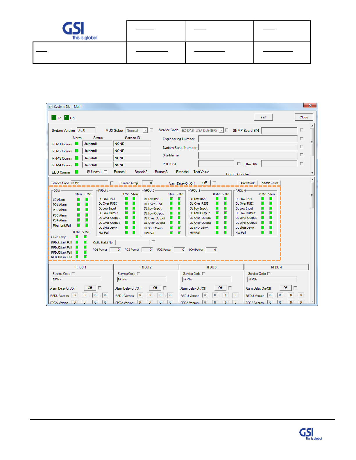
7.3. Main Screen
• GUI Screen for Main Menu
• Able to select system that user control, Configuration & Status monitoring
• Green means that the system is operating under normal condition.
• Red means that the system is operating under abnormal condition. In other words, system is likely non-working.
• Gray means that the system is not linked or communicated fail. But if it is not communicated between DU and
© 2018 GS Instech Co., Ltd. All rights reserved.
SU, Donor Unit is also changed Red.
32
Page 33
Version
0.1
Date
May 11, 2018
Page
33/ 42
Title
USER MANUAL
Prepared by
Reviewed by
Approved by
7.4. RF Status
• GUI Screen for display Repeater’s RF Status
© 2018 GS Instech Co., Ltd. All rights reserved.
33
Page 34

Version
0.1
Date
May 11, 2018
Page
34/ 42
Title
USER MANUAL
Prepared by
Reviewed by
Approved by
7.5. RF Configuration
• GUI Screen in order to change the RF values
• User may change the various RF values of the repeater on this page
• Changes will not take effect until you click "Apply" button
• This menu is where the installer will choose references for specific implementation
34
© 2018 GS Instech Co., Ltd. All rights reserved.
Page 35
Version
0.1
Date
May 11, 2018
Page
35/ 42
Title
USER MANUAL
Prepared by
Reviewed by
Approved by
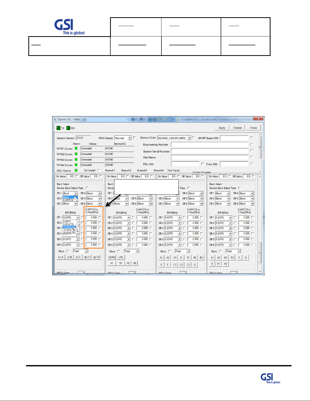
Write the Fc or EARFCN
7.6. Band Selection
• Repeater support the capacity of CDMA and LTE Technologies
• Ability to set the 6 Non-Contiguous channel
• Support the CDMA 15MHz max per 1.25 step and LTE 5MHz, 10MHz, 20MHz
• User can set the desired channel using the GUI
© 2018 GS Instech Co., Ltd. All rights reserved.
35
Page 36
Version
0.1
Date
May 11, 2018
Page
36/ 42
Title
USER MANUAL
Prepared by
Reviewed by
Approved by
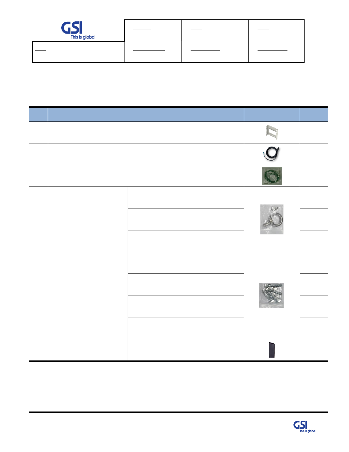
#
Contents
Picture
Q’ty
1
Mounting Bracket
1EA
2
AC Power Cable SJT 3/16 AWG, 6ft
1EA
3
Frame Ground Cable with Tubular Cable Lug, 6ft
1EA
4
Installation purchase set
EYE BOLT(M12)
1EA
M5x12mm WRENCH BOLT, SEMS
2EA
PH(+) M4x8mm ,SEMS
4EA
5
Mounting Screw set
LAG SCREW 3/8”x3”
2EA
HEX HEAD 3/8”x2”, SCM440
2EA
Φ10.5mm/Φ21mm PLAIN WASHER
2EA
Φ10.2mm/Φ18.4mm SPRING WASHER
2EA
6
Tubing Tube Sleeve Black
Φ30mm/L:150mm Adhesive Polyolefin
3:1 Heat Shrink
1EA
8. System Installation
• This chapter describes how to install the repeater and Cabling method
• The needed accessories and tools are list up as below
© 2018 GS Instech Co., Ltd. All rights reserved.
Table 13. EZ-DAS Installation Accessories
36
Page 37
Version
0.1
Date
May 11, 2018
Page
37/ 42
Title
USER MANUAL
Prepared by
Reviewed by
Approved by
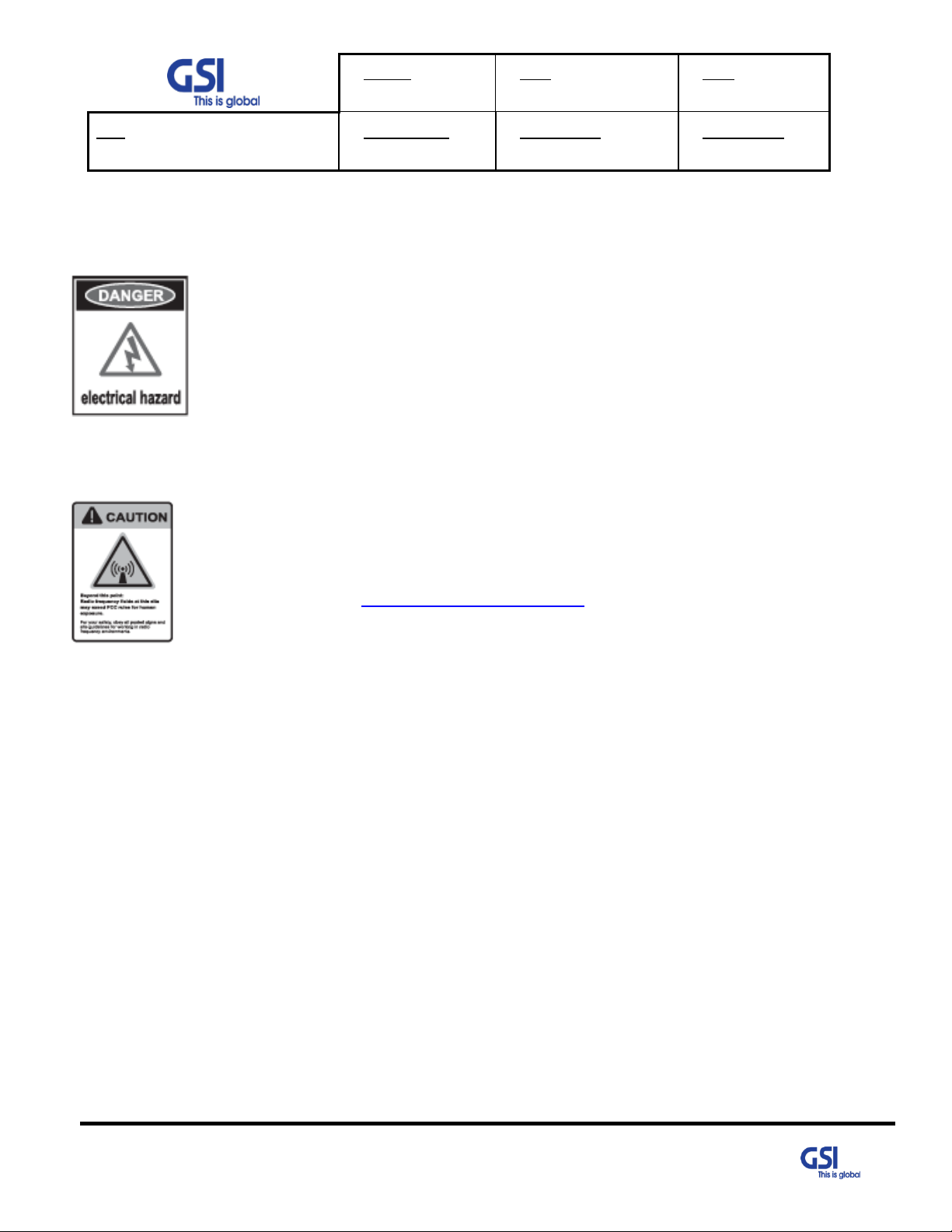
8.1. Warnings and Hazards
8.1.1. Electric Shock
• Opening the Repeater could result in electrical shock and may cause severe
injury
• Operating the Repeater with antennas in very close proximity facing each other
could lead to severe damage to the repeater
8.1.2. Exposure to RF
Working with the repeater while in operation, may expose the technician to
RF electromagnetic fields that exceed FCC Rules for human expose.
Visit the FCC Website at http://www.fcc.gov/oet/rfsafety to learn more about
The effects of exposure to RF electromagnetic fields
© 2018 GS Instech Co., Ltd. All rights reserved.
37
Page 38

Version
0.1
Date
May 11, 2018
Page
38/ 42
Title
USER MANUAL
Prepared by
Reviewed by
Approved by
Protection gloves and goggles
Make sure that worker wears protection gloves and goggles to prevent damages from
debris while drilling holes in a Pole or Wall
LAG SCREW 3/8"x3"
Φ10.5mm/Φ21mm PLAIN WASHER
Φ10.2mm/Φ18.4mm SPRING WASHER
8.2. Service Man Installation Guide
8.2.1. Wall Mount Installation
The procedure for fixing the pole type system is as follows.
Service man is mounting the same way the EZD-LICPA23 and EZS-LICPA30.
1) To mount the system on the wall, first fix the bracket on the wanted position.
2) Hang the system to the hooking position at the top of the mounting bracket
3) Push the system to the hooking position at the bottom of the mounting bracket.
Figure 13. The way to fix the bracket on the pole (Normal type)
38
© 2018 GS Instech Co., Ltd. All rights reserved.
Page 39

Version
0.1
Date
May 11, 2018
Page
39/ 42
Title
USER MANUAL
Prepared by
Reviewed by
Approved by
Cautions while drilling on the pole
Drilling thru-hole on a center of the pole
Cautions System leveling
Before fixing the system, Check the horizontal and vertical level using a spirit level
M5x12mm WRENCH BOLT, SEMS
4) Align the system with the fixing holes of the mounting bracket and fix them firmly
Figure 14. The way to fix firmly the System for Pole Mounting
39
© 2018 GS Instech Co., Ltd. All rights reserved.
Page 40
Version
0.1
Date
May 11, 2018
Page
40/ 42
Title
USER MANUAL
Prepared by
Reviewed by
Approved by
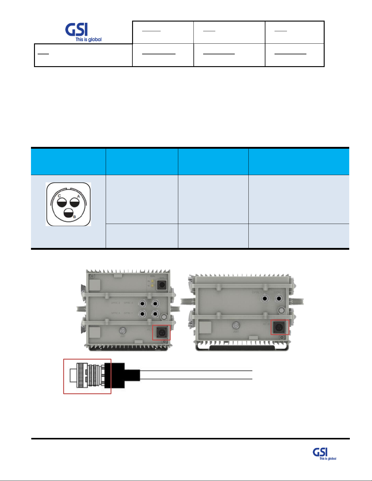
Port Outlook
(System Side)
Port numbering
for MS
NAME
Description
MS-3102A-10SL-3P
A
AC_H
AC Hot
B
AC_N
AC Neutral
C
F.G
Frame Ground
A
A
A
8.3. Cable Connection
8.3.1. AC Power cable connection
• Repeater supports a free AC Input voltage from 110V to 240V
• Provided Power cable is single type, so it can be used flexibly
• The pin description of AC Port is below. User should connect exact polarity of AC
• The specification & Connection of AC Power Cable
- A: MS3106A-22-2
- Connect Port A for inserting AC Power
© 2018 GS Instech Co., Ltd. All rights reserved.
40
Page 41

Version
0.1
Date
May 11, 2018
Page
41/ 42
Title
USER MANUAL
Prepared by
Reviewed by
Approved by
Frame Ground
8.3.2. Local Maintenance Connection
• Repeater Support a RJ-45 connector
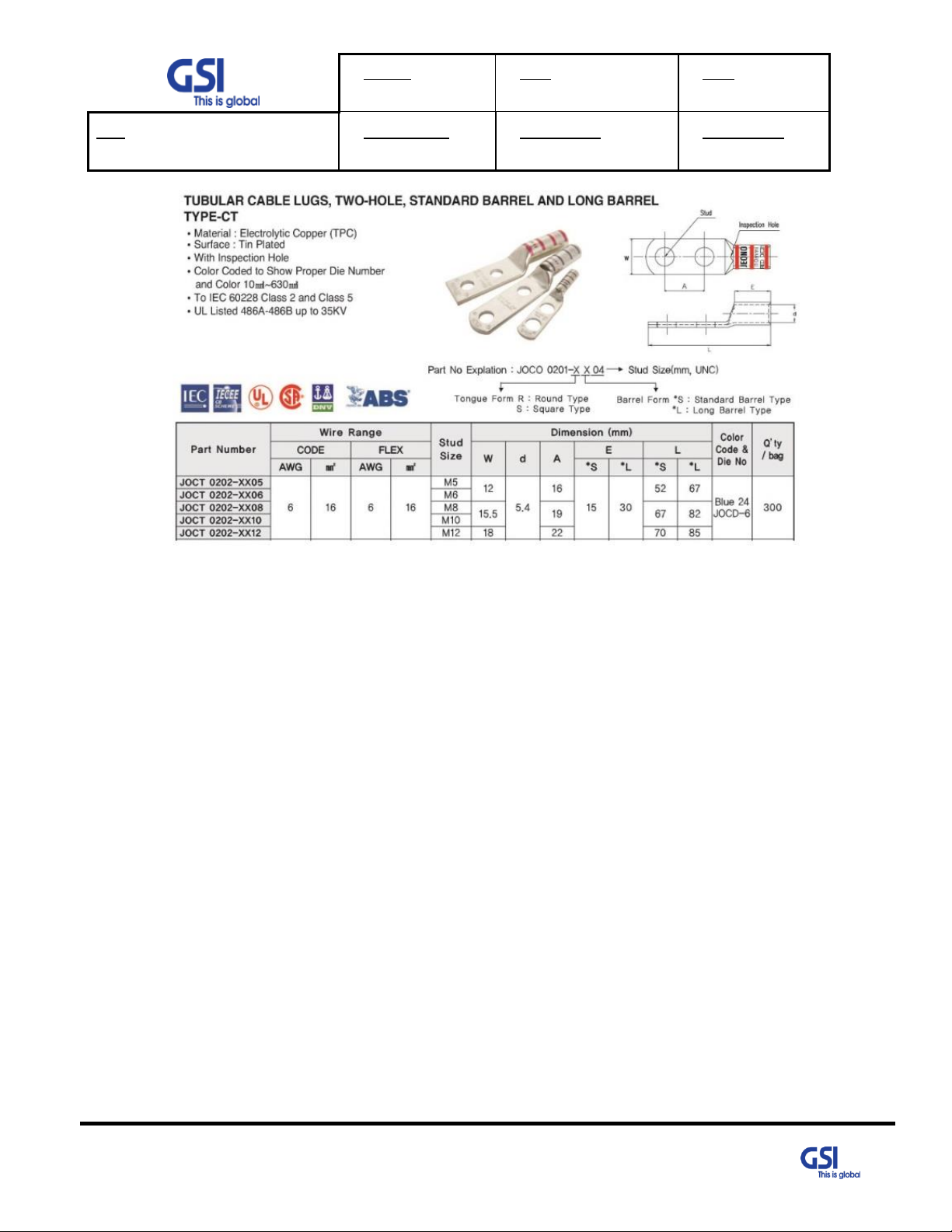
8.3.3. Grounding cable Connection
• Frame(Earth) Wire size is AWG #6. The way to install the grounding cable is below
• The specification of ground terminal lug is like below (Refer to JOCT 0202-RL05)
© 2018 GS Instech Co., Ltd. All rights reserved.
41
Page 42
Version
0.1
Date
May 11, 2018
Page
42/ 42
Title
USER MANUAL
Prepared by
Reviewed by
Approved by
© 2018 GS Instech Co., Ltd. All rights reserved.
42
 Loading...