

Page 1

Clear Call
User Manual
Version 1.1
GSInstech Co., Ltd
GSInstech Co., Ltd
Page 2
Revision History
Version
Author
Descriptions
Date
Remarks
1.0
S.H Yoo
Draft
1 Aug 2018
1.1
S.H Yoo
FCC Label
6 Sep 2018
System Installation
Version
Change List
Remarks
Change List
GSInstech Co., Ltd
Page 3
Abbreviations
Abbreviation
Term Definition
Remark
AGC
Automatic Gain Control
ALC
Automatic Level Control
BTS
Base Transceiver Station
CW
Continuous Wave (un-modulated signal)
DFM
Digital Filter Module
DL
Downlink The path covered from the BTS to the subscribers
service area via the repeater
FW
Firmware
HPA
High Power Amplifier
HW
Hardware
LNA
Low Noise Amplifier
LTE
Long Term Evolution
MS
Mobile Station
PSU
Power Supply Unit
RF
Radio Frequency
RFU
Radio Frequency Drive Unit
SW
Software
UL
Uplink The path covered from the subscribers service area to
the BTS via the repeater
VSWR
Voltage Standing Wave Ratio
GSInstech Co., Ltd
Page 4
FCC ID(s)
HAAT (m)
Max. Antenna again
U88CC-L13
71656.75
6 dBi
U88CC-I13
26460.60
6 dBi
U88CC-P18
26143.43
6 dBi
U88CC-A18
72828.84
6 dBi
1. FCC Mandatory
1.1 FCC Warning States
1.1.1 FCC Part 15.21
Any changes or modifications not expressly approved by the party responsible for
compliance could void the user's authority to operate this equipment.
1.1.2 FCC Part 15.105
This equipment has been tested and found to comply with the limits for a Class A digital
device, pursuant to part 15 of the FCC Rules. These limits are designed to provide
reasonable protection against harmful interference when the equipment is operated in a
commercial environment. This equipment generates, uses, and can radiate radio frequency
energy and, if not installed and used in accordance with the instruction manual, may cause
harmful interference to radio communications. Operation of this equipment in a residential
area is likely to cause harmful interference in which case the user will be required to correct
the interference at his own expense.
1.1.3 FCC Part 15.19
This device complies with Part 15 of the FCC Rules. Operation is subject to the following two
conditions: (1) this device may not cause harmful interference, and (2) this device must
accept any interference received, including interference that may cause undesired operation.
1.1.4 Antenna installation
. Antennas must be installed in accordance with FCC requirement.
The height of the antenna above average terrain (HAAT) must not exceed limit in the
following table.
1.1.5 Radiation Exposure Statement
GSInstech Co., Ltd
RF Radiation Exposure
This equipment complies with RF radiation exposure limits set forth for an uncontrolled
environment. This equipment should be installed and operated with a minimum distance of
Page 5
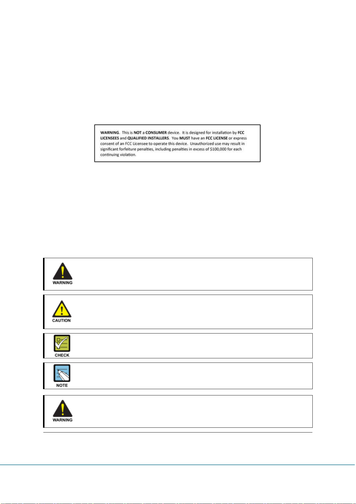
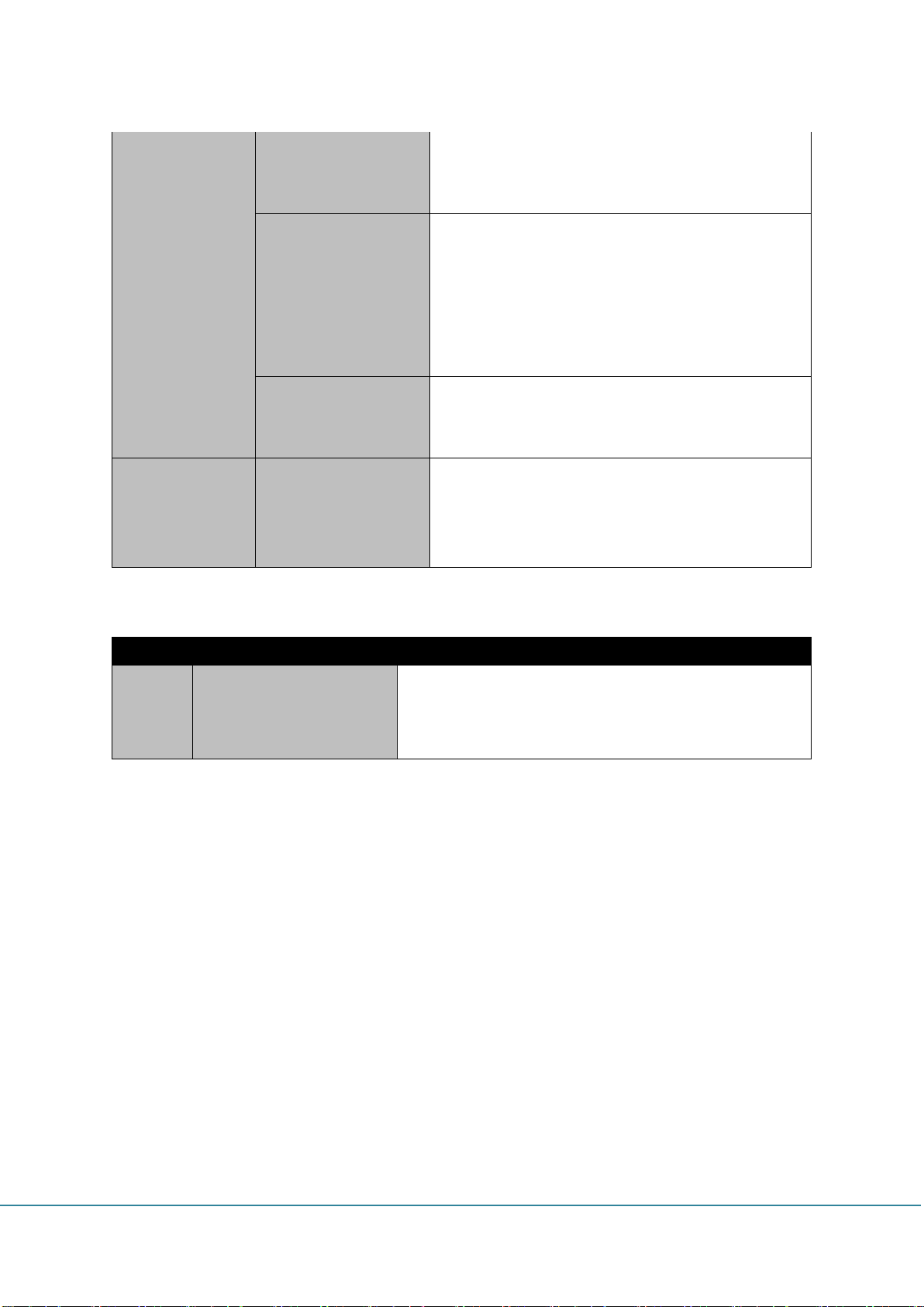
WARNING
Provides information or instructions that the reader should follow in order to avoid
personal injury or fatality
CAUTION
Provides information or instructions that the reader should follow in order to avoid
a service failure or damage to the system
CHECK POINT
Provides the operator with checkpoint for stable system operation
NOTE
Indicates additional information as a reference
No use for the unauthorized device
When installing the system. Must check the devices that use is authorized.
This conditions apply antenna, cable, and if necessary
20 cm between the radiator and your body. This transmitter must not be co-located or
operating in conjunction with any other antenna or transmitter. RF exposure will be
addressed at time of installation and the use of higher gain antennas may require larger
separation distances.
1.1.6 FCC Warning Labels
1) FCC Part
1.2 Prohibitions
Use of unauthorized antennas, cables, and coupling devices not conform to ERP/EIRP
and indoor‐only restrictions is prohibited.
Preclude indications that home/personal use be prohibited.
1.3 Installation Warning statement
GSInstech Co., Ltd
Page 6
Circuit Breaker Installation in the Box for Overcurrent Protection
Must install the circuit breaker between the system and main AC source for
separating.
Make sure to install the Circuit breaker on the place to operate easily Circuit breaker
be able to operate up to 20A
Terminal, Conduit and Cable size
To install the conduit is according to NAE regulation, and Terminal size is according
to NEC regulation
GSInstech Co., Ltd
Page 7
Certification
Type
ID
Remarks
FCC
Industrial RF Repeater
U88CC-L13
700MHz
U88CC-I13
800MHz
U88CC-P18
1900MHz
U88CC-A18
2100MHz
General Information
This document is primarily written for those who are new to Clear Call system and wish to
tune up the equipment. The document is applicable to below products from GSINSTECH.
Model number: Clear Call.
1.4 Repeater Information (FCC)
1.5 Purpose
Clear Call is a repeater, which has been designed to improve signals in blanket/shadow
areas inside of buildings to transmit Provider’s variety frequencies. User may choose filtering
configuration according to the specific site circumstances. It supports 700MHz LTE, 800MHz
iDEN, 850MHz Cellular, 1900MHz PCS and 2100MHz AWS frequency with one antenna
port. The max output is 18dBm and coverage is up to 25,000 SQFT.
1.6 Advantages
It provides selectable RF power levels for any wireless technology/band
19inch rack or wall mount available depending on the installation site
Modular type for each frequency up to 4 modules
Can select service band through RSSI
Check and control the status of the repeater through front touch LCD
FPGA digital filtering provides optimized RF performance
Sub band filtering: It contains three non-contiguous high rejection digital filter
Quad band channel filtering, real time oscillation detect & gain control
GSInstech Co., Ltd
Page 8
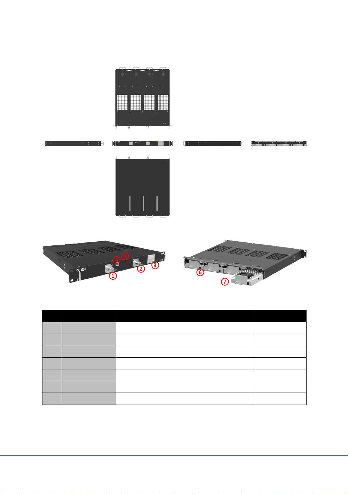
No
Description
Function
Remarks
1
Donor ANT Port
Antenna port for communication with BTS
4.3-10 DIN
2
Service ANT Port
Antenna port for communication with terminal/UE
4.3-10 DIN
3
Touch LCD
Display of status and select of function
2.2inch TFT LCD
4
Ethernet Port
GUI connection port for checking the status and control
RJ-45
5
Debug Port
Communication port for developer
Micro USB
6
Power Supply Port
Power supply port for each module
DC-005 jack
7
RF Unit
RF service unit
Max 4 unit
1.7 Appearance
GSInstech Co., Ltd
Page 9
Item
Specification
Remark
700MHz
Down Link
728MHz ~ 757MHz
Band 12 & 13
Up Link
698MHz ~ 716MHz
Band 12
776MHz ~ 787MHz
Band 13
800MHz
Down Link
862MHz ~ 894MHz
Band 26
Up Link
817MHz ~ 849MHz
Band 26
1900MHz
Down Link
1930MHz ~ 1995MHz
Band 25
Up Link
1850MHz ~ 1915MHz
Band 25
2100MHz
Down Link
2110MHz ~ 2155MHz
Band 4
Up Link
1710MHz ~ 1755MHz
Band 4
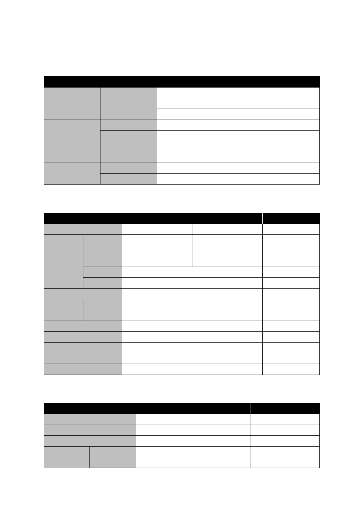
Item
Specification
Remark
Band
700MHz
800MHz
1900MHz
2100MHz
Composite
Power
DL
13dBm
13dBm
18dBm
18dBm
UL
18dBm
18dBm
18dBm
18dBm
Gain
Range
75 ~ 45dB
80 ~ 50dB
Step
0.5dB
Accuracy
1dB
Roll-Off
-50dBc @ ±750kHz
Flatness
Single CH
≤ 4dB
Inter CH
≤ 5dB
UL Noise Figure
≤ 7dB
@ Max Gain
Group Delay
≤ 5us
Channel Select
Non-Contiguous 3Block
In/Out Port VSWR
2.0 : 1
Impedance
50Ω
Item
Specification
Remark
RF Connector
DIN (4.3-10) Type Female
AC-DC Adapter
Input : AC 90 ~ 264V, Output : DC 12V
DC Power Connector
DC-005
Size
Module
4.17 * 12.6 * 1.6inch
(106 * 321 * 40.9mm)
2. Specifications
2.1 Frequency Allocation
2.2 Common Specifications
2.3 Mechanical Spec.
GSInstech Co., Ltd
Page 10
Chassis
17.2 * 18.1 * 1.75inch
(437 * 457.5 * 44.5mm)
Weight
Module
< 2.98lbs (1.35Kg)
Chassis
< 19.84lbs (9Kg)
Included four modules
Operation Temperature
32 ~ 122°F (0 ~ 50°C)
Humidity
0 ~ 80%
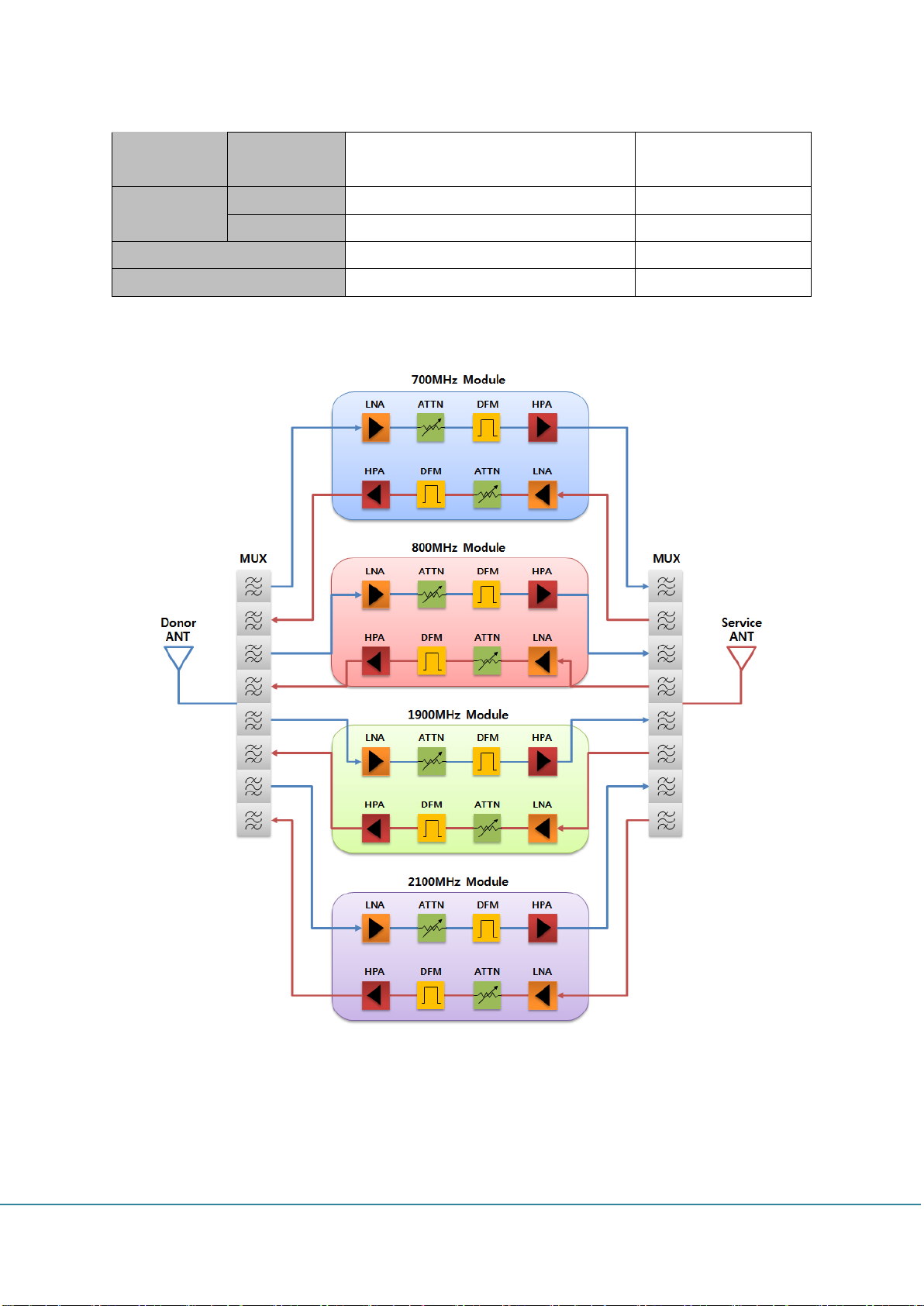
2.4 Block Diagram
GSInstech Co., Ltd
Page 11

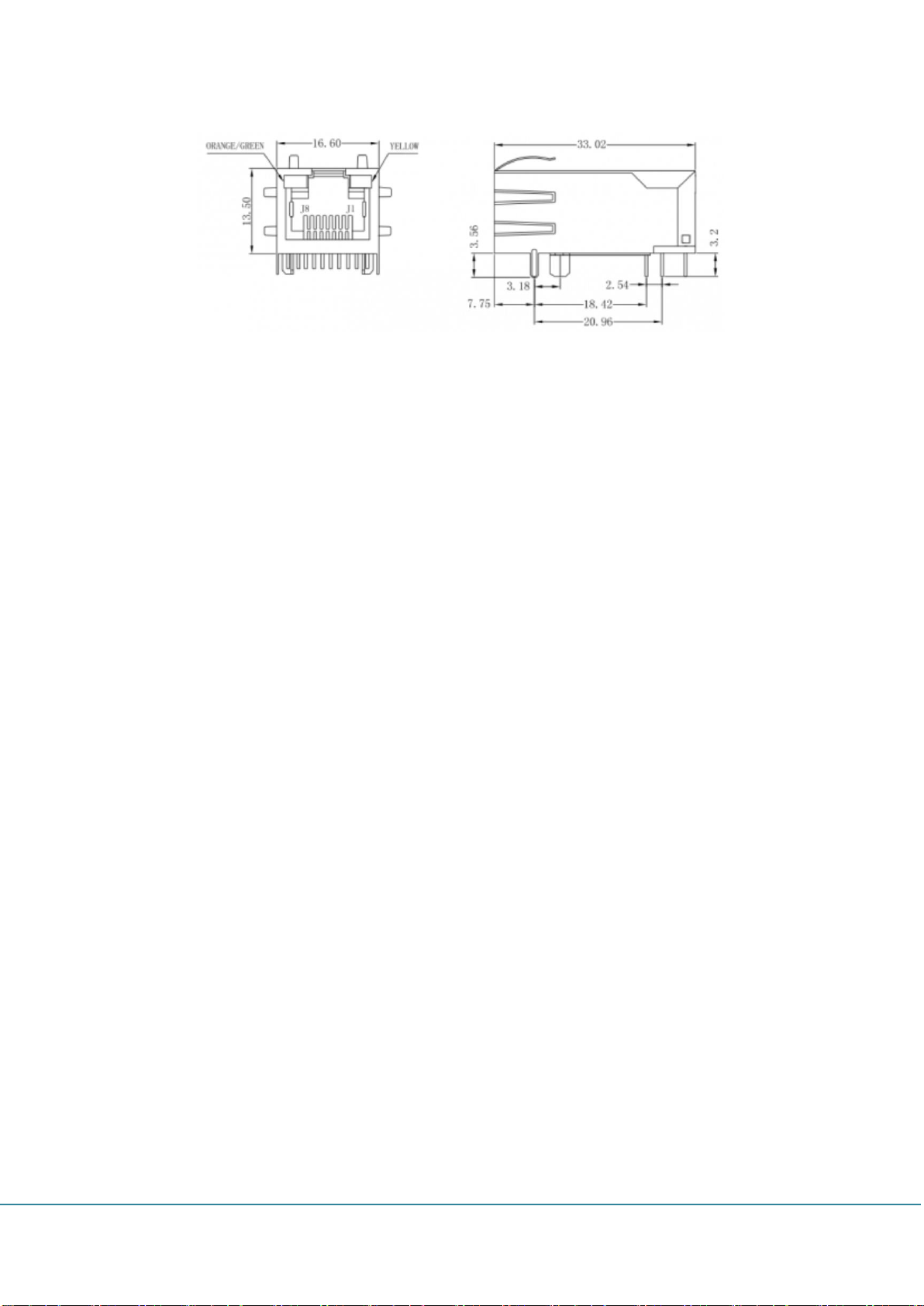
3. Port and Connectors
3.1 RF Connector
Clear Call adopts is a Mini-DIN 4.3/10 connector. If the user wants to use an N type cable or
connector, they need an adaptor.
3.2 DC Power Connector
Clear Call uses only DC 12V. If the user uses other un-recommend input voltages, may be
broken. The DC power connector of the Clear Call uses type-B. The outside diameter is
3.5mm and inside diameter is 1.35mm.
3.3 Ethernet Port
Clear Call can be connected to the SNMP via Ethernet, and the user can use the WEB UI to
control and monitor in remote or local locations.
GSInstech Co., Ltd
Page 12
GSInstech Co., Ltd
Page 13
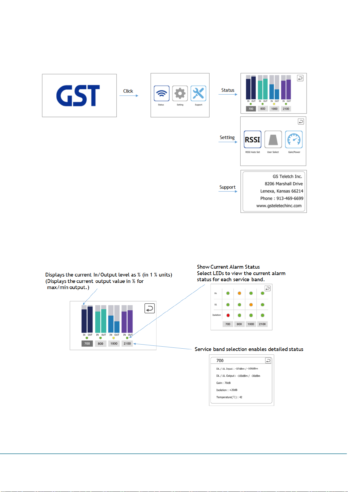
4. LCD Information
4.1 LCD Display Gate
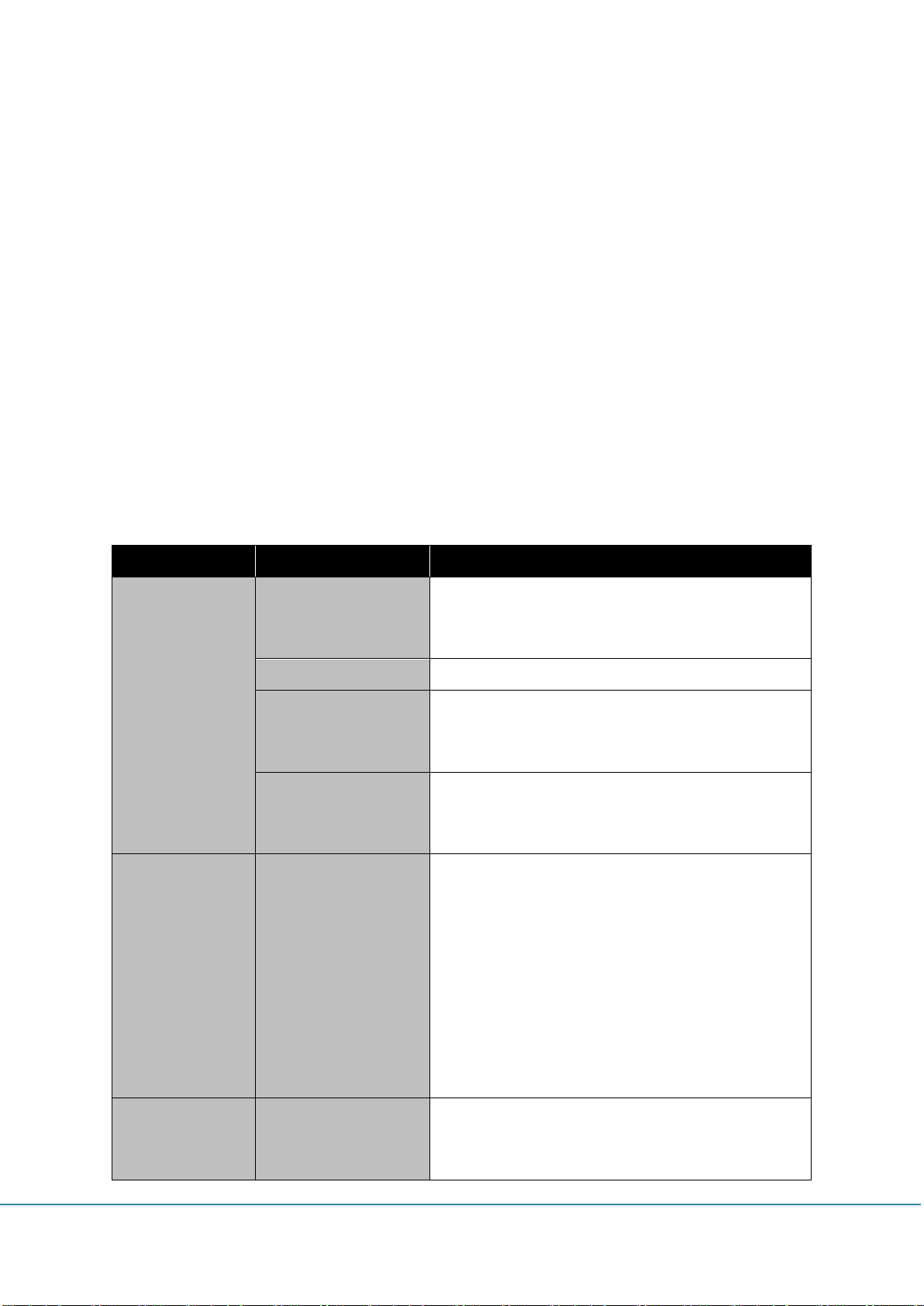
4.2 Status
GSInstech Co., Ltd
Page 14

4.3 Setting
4.3.1 RSSI
GSInstech Co., Ltd
Page 15

4.3.2 User Select
4.3.3 Gain/Power
GSInstech Co., Ltd
Page 16

4.4 Support
Shows addresses and contact numbers for a tech call if there is a problem with the
equipment.
GSInstech Co., Ltd
Page 17

5. Graphic User Interface
5.1 Program Usage
1) Connect your laptop to the repeater with a direct Ethernet cable.
2) Click the following icon to run the GUI program.
3) Connect to IP: 192.168.1.1, Port: 9000 with UDP communication.
4) Select a module per unit to verify that the module is mounted. (Install/Uninstall)
GSInstech Co., Ltd
Page 18

No.
Description
1
Data transfer/receiving status display
2
> System: System map open
> DFM: DFM(Module) open the view/control window for Independent use
3
> Table: Table window open
> Download: Download window open
> Debug: Debug window open
5) In case of control, press ‘SET’ to enter control mode.
6) Change what you want to control. To complete the change and send a control request, press
‘Apply’.
7) The next item automatically displays the check box. You can cancel the control of the item by
releasing the displayed check box. You can also cancel all controls by pressing ‘Cancel’.
8) There is a response wait of 5 seconds. Only when the response is not in time, shows the
‘Time Out’ message.
9) After the control is finished, the status check is automatically performed again. At this point, it
can be checked that the value is applied.
5.2 Start window
5.2.1 Start window
GSInstech Co., Ltd
Page 19

4
Connection settings window. Serial/UDP/TCP can be one selected
5
Connect/Disconnect can be one selected
6
System Map
You can view simple information about each module in SNMP.
> LED
- Green: Install
- Red: Alarm
- Yellow: Link Fail
- Gray: Uninstall
> DFM 1 / 2 / 3 / 4: Open the view/control status window of SNMP and each DFM
> 700 / 800 / 1900 / 2100: Module connected to the location
> Install / Uninstall: Module fitted
No.
Description
1
Serial COM port setting
> refresh: COM port refresh
2
Serial communication speed setting
Use 115,200 when connecting DFM alone
No.
Description
1
IP address setting
2
Port setting
5.2.2 Communication Settings window
1) Serial
2) UDP/TCP
5.3 System main window
5.3.1 Main window
GSInstech Co., Ltd
Page 20

No.
Description
1
Data transfer/receiving status display
2
> Control mode
- SET/Apply: Enter control mode, run control
- Cancel: Cancel control
- Close: Close main window
3
SNMP main: SNMP information
4
DFM main: DFM information
5
Service band view/control. Located in its GUI for each module (707/800/1900/2100)
6
SNMP, LCD, DFM and FPGA version
5.3.2 SNMP window
GSInstech Co., Ltd
Page 21

No.
Description
1
SNMP reset
2
Communication counter. Increase by 1 each time the corresponding equipment communicates
with SNMP
No.
Description
1
Allow specific alarms to be masked
5.3.3 Alarm Mask window
5.3.4 DSP window
GSInstech Co., Ltd
Page 22

No.
Description
1
Local frequency and gain of DSP. The default setting does not require the user to set it.
No.
Description
1
Setting initialization
2
Service band information (Bandwidth, Center Frequency, EARFCN)
3
Service band auto setting
Automatically set the service band by measuring the RSSI
5.3.5 Hidden window
GSInstech Co., Ltd
Page 23

No.
Description
1
Target Selection
Select the destination for read/write table information
> Link: Destination associated with PC (SNMP/DFM)
> Unit: What kind of read/write actual data
> Unit No: Select target. Exists only in situations where multiple choices are available
2
Commands to read/write table information
> Read: Request to read table data
> Write: Request to read table data. Apply the table data change if you issue the command.
3
Table information display window
> Index: Data display and target value
> Value: Actual settings (V, dB)
> Chk: Used by Sprading. Serve as a benchmark
4
Table Setup Area
> Table: Select table type
> Default Range: Set default range
> Start Value: Set range start value
> Length: Set range length
> Setting: Apply range setting
The range is reduced from the starting value to a certain value (Step), and only a length is
generated.
5.4 Table
GSInstech Co., Ltd
Page 24

> Item: Selected item index value
> Value: The selected item value. Can be changed
> Chk: Selected Chk value. Can be changed
> Set: Modify selected item
> Detect: Ability to insert real detect values directly
- First box: Display the corresponding index value. Optional
- Second box: Increase in index value
- Text box: print current detect value
- Set: Enter the current detect value in the corresponding index.
Then move the index increments to select the next index.
> Offset: The set value is added only to the total value
> Zero Set: Set all value settings to zero
> Sprading: To divide values evenly between items marked with two
> File Save: Save the current table
> File Load: Load table value from file
No.
Description
1
Target Selection
Select the destination for read/write table information
> Link: Destination associated with PC (SNMP/DFM)
> Unit: What kind of read/write actual data
> Unit No: Select target. Exists only in situations where multiple choices are available
- No1: 700, No2: 800, No3: 1900, No4: 2100
2
Download Start/End
> Start: Download start. Activation occurs only when the file path is correct.
> Close: Close the window. Stop downloading while the download is in progress
5.5 Download
GSInstech Co., Ltd
Page 25

3
Download Settings and Information Display
> Target: Type of file to download (Application/FPGA)
> File Path: Path where destination file is located.
You can find it by typing directly or by selecting Open next to it.
> File Frame: Number of frames divided by files
> Frame Size: Bytes per frame
> File Size: File size
> Total CRC : Total CRC of download file
> Progress: Display current download progress
> Frame: The frame number currently being transferred
> Time: Download time
No.
Description
1
Debug Control Panel
> Start: Start the automatic status check request
> Pause: Stop automatic status check request
> Clear: Clear record of data log window
> Close: Close the window
5.6 Debug
GSInstech Co., Ltd
Page 26

2
Debug Log Panel
Displays transfer/receiving data in real time
3
Debug Test Panel
Receive data can be entered directly. No data is received which violates Clear Call protocol
GSInstech Co., Ltd
Page 27

No.
Picture
Item
Remark
1 Donor Antenna (Patch)
4dBi / 6dBi (700M, 800M /
1900M, 2100M)
2 Service Antenna (Omni)
2dBi / 4dBi (700M, 800M /
1900M, 2100M)
3
Antenna Link Cable x 2
3D-FV 30ft
4 4.3-10 mini DIN to N Adapter x 2
5
AC/DC Adapter
12V DC/5A
(For each Module)
6 Lightning Surge Protector
6kV/3kA
7 Wall Mounting Kit
6. Installation
6.1 Installation Accessories
6.2 System Installation
Clear Call can be installed on 19inch racks or walls depending on the installation site.
6.2.1 Rack Mount
6.2.2 Wall Mount
GSInstech Co., Ltd
Page 28

6.3 Installation Precaution
6.3.1 Antenna
The antenna used in the Clear Call must be certified or an antenna with equivalent
specifications.
The company shall not bear any liability for any problems arising from the use of an
uncertified antenna.
6.3.2 Isolation
If the system wants to operate in the max gain state, the system requires sufficient isolation
between the donor and service antennas.
The system recommends isolation is higher than 15dB above the gain of the system.
If isolation is not sufficiently ensured, the AOC function operates to reduce the gain to a level
suitable for the ensured isolation.
6.3.3 Check points before turning on the Repeater
1) System Power Check
DC electrical power to the repeater should be 12V, input electricity only after power
verification.
2) Input RF Signal Range
Optimal input RSSI into the repeater is -62dBm ~ -32dBm for all band. User should verify
input condition of Donor ANT. If the input RSSI exceeds -32dBm, impose the using external
attenuators should be used.
3) Isolation check between Donor/Service ANT
The system must need that 95dB(Gain+15dB) isolation is secured to use 80dB of the
maximum profit of the system. User should check its condition before installation.
GSInstech Co., Ltd
Page 29

6.3.4 Open for Service
1) Check points before open:
① Verification of system installation status :
Electricity, In/Out antennas, cable connection, and equipment mount status.
② Verification of system accessories :
User should check all necessary accessories.
③ Check receipt signal level :
Installer should check whether environmental conditions are in accordance with
system specification to ensure that system operation will be optimized.
GSInstech Co., Ltd
Page 30
Item
Check Point
Troubleshooting
Check before
system operation
System input power
range (DL/UL)
- Downlink: -62dBm ~ -32dBm
- Uplink: -57dBm ~ -27dBm (@ 700MHz/800MHz)
- Uplink: -62dBm ~ -32dBm (@ 1900MHz/2100MHz)
System gain (DL/UL)
- 50dB ~ 80dB
Output power
(DL/UL)
- Downlink: 13dBm±2dB (@ 700MHz/800MHz)
- Downlink: 18dBm±2dB (@ 1900MHz/2100MHz)
- Uplink: 18dBm±2dB
Check points before
open for service
- Please check quantity of all accessories with
specification before you set up
- Fit cable length in accordance with field condition
Check after
system operation
Check points after
open for service
Check following status;
- Verify that the antennas are securely mounted and
pointed in the correct directions
- Connection status between antennas and RF cable
- Verify that the Repeater is securely mounted
- Proper AC power status for AC/DC Adaptor
- Coaxial cable (RF) construction status
- Connectors and combiners connection status
- Cable connection status against leakage of water
When repeater
does not work
properly
Check electricity cord
connection status
- Re-Connection in power cable
7. Troubleshooting
7.1 Troubleshooting
In case of abnormal operation, technician should diagnose abnormality via remote access or
directly connecting to repeater using Ethernet cable. If technician is required to conduct
repairs due to major alarm, repeater should first be powered off, and then technician should
prepare the proper measurement equipment before trying to fix the problem. In most cases of
major repairs, GST will simply replace the unit and conduct repairs at the appropriate facility.
7.1.1 Simple Troubleshooting Method
1) Check LED status at rear of module
- Normal operation: Green LED on. Alarming: Red LED on.
2) Technician should check external and internal connectors to ensure that all connections
are tightly secure. These connectors should be cleaned regularly.
3) If technician thinks there is a serious problem, call after sales team for over-the-phone
technical support. 1-913-469-6699.
7.1.2 Troubleshooting Guide Related to RF
GSInstech Co., Ltd
Page 31
DL / UL
over output alarm
- Make sure output power is operating normally
- Please reset adaptor upon completing alarm
troubleshooting
Temperature alarm
Check following status;
- Setting level of maximum temperature limit
- Temperature offset is normal or not
- Circumstances of temperature
- Please reset adaptor upon completing alarm
troubleshooting
RF off
- Verify that the HPA’s are on
- Please reset adapter upon completing alarm
troubleshooting
When output
power is no
longer problem
Technician should
verify category of
alarm at the LCD of
front side.
- When red light on the shutdown LED, technician
should troubleshoot the alarm via laptop
Symptom
Check Points
Troubleshooting
Link Fail
Communication problem
In case of Ethernet, verify IP addressing, DHCP function,
and that cookies are deleted
- verify that a direct Ethernet cable is being used
7.1.3 Troubleshooting Guide Related to SNMP
If technician thinks there is a serious problem, call after sales team for over-the-phone
Technical support. 1-913-469-6699.
GSInstech Co., Ltd
 Loading...