

Page 1
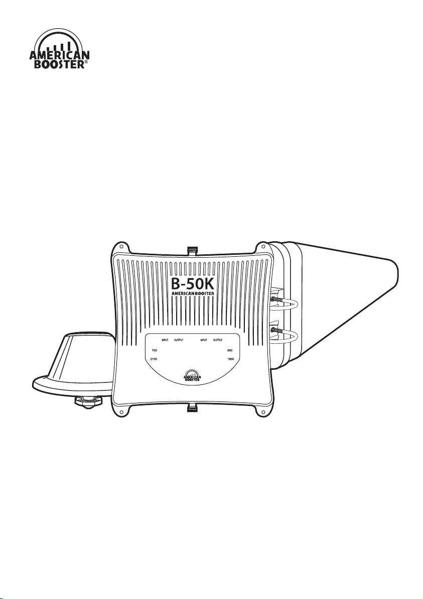
B-50K
User Guide
Building Cellular Signal Booster
Page 2
This publication provides instructions for installing Cellular Signal Booster B-50K.
Copyright© 2018, American Booster Inc.
All Rights Reserved.
Revision History
Date
2018, November Version 1.0 Original
Certication
This equipment complies with the FCC directives.
Version Changes
Technical Support : 913 469 6699 www.americanbst.com
Page 3

INDEX
Product Introduction
Package Contents
Application Example
B-50K Optional Components
Installation Guide
STEP 1. Find the Strongest Signal
STEP 2. Install the Outside Antenna
STEP 3. Run the Outside Antenna Cable
STEP 4. Install the Inside Antenna
STEP 5. Install the Signal Booster
LED Status & Troubleshooting
LED Bar Display
Functions
Specications
4
5
6
7
8
8
10
12
14
16
18
20
21
22
Safety Guidelines
Warranty
Memo
23
25
26
Page 4
B-50K
Yagi Antenna
American Booster B-50K has been designed to improve and extend cellular coverage
®
inside the buildings. B-50K amplies signals from the nearest base station and re-transmits them
at higher power level. B-50K provides service at 700MHz LTE, 850MHz Cellular, 1900MHz PCS and
2100MHz AWS frequencies without any additional setup or conguration.
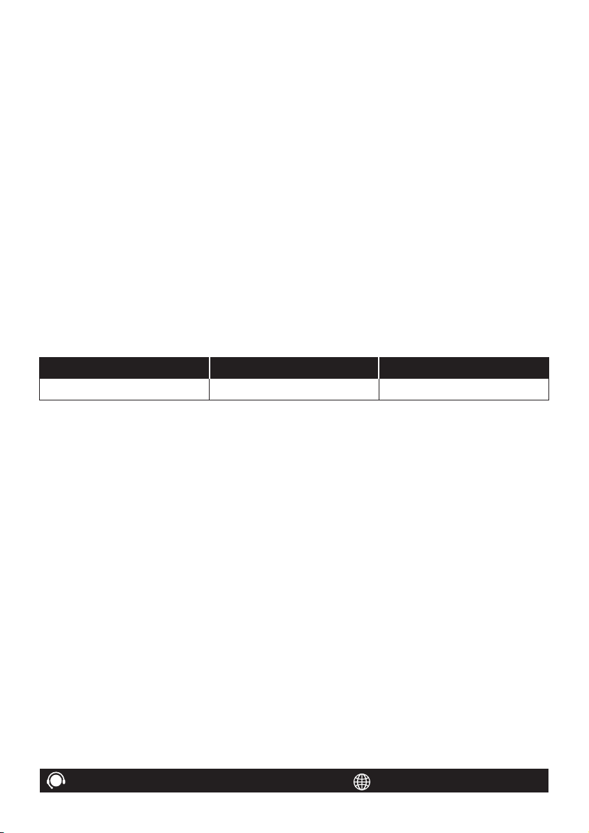
How it works
Receives Signal
The signal booster’s outside
antenna receives voice and
data signals from a nearby
cell tower.
Receives Signal
The signal booster receives
the signal from the outside
antenna and after amplifying
the voice and data signals, sends
them to the inside antenna.
Improves Signal
The inside antenna
distributes the boosted
signals inside your building.
4
B-50K User Guide
Page 5
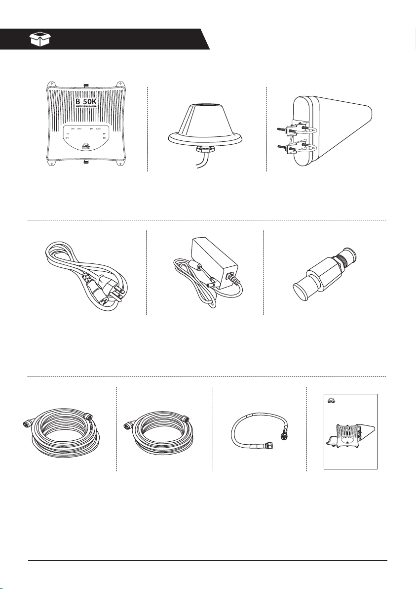
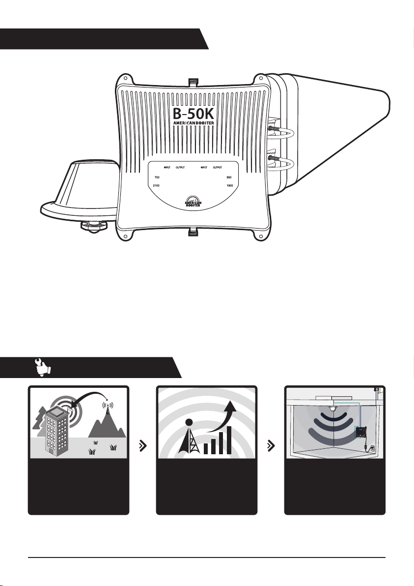
Package Contents
Signal Booster B-50K
Code No. : 0168
AC Power Cord
Code No. : 82W54
Inside Antenna Kit
Code No. : 83617
AC/DC Adaptor
Code No. : 833PU
Outside Antenna Kit
Code No. : 83615
Lightning Protector
Code No. : 834TJ
B-50K
User Guide
Building Cellular Signal Booster
Coaxial Cable 100 ft.
Code No. : 834TL
Coaxial Cable 75 ft.
Code No. : 834TP
B-50K User Guide
Coaxial Cable 2 ft.
Code No. : 834TK
User Guide
5
Page 6
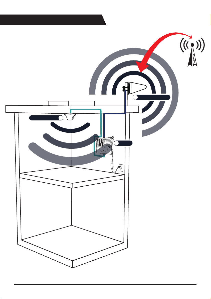
Application Example
1
Outside Antenna
Inside Antenna
3
2
B-50K
6
B-50K User Guide
Page 7
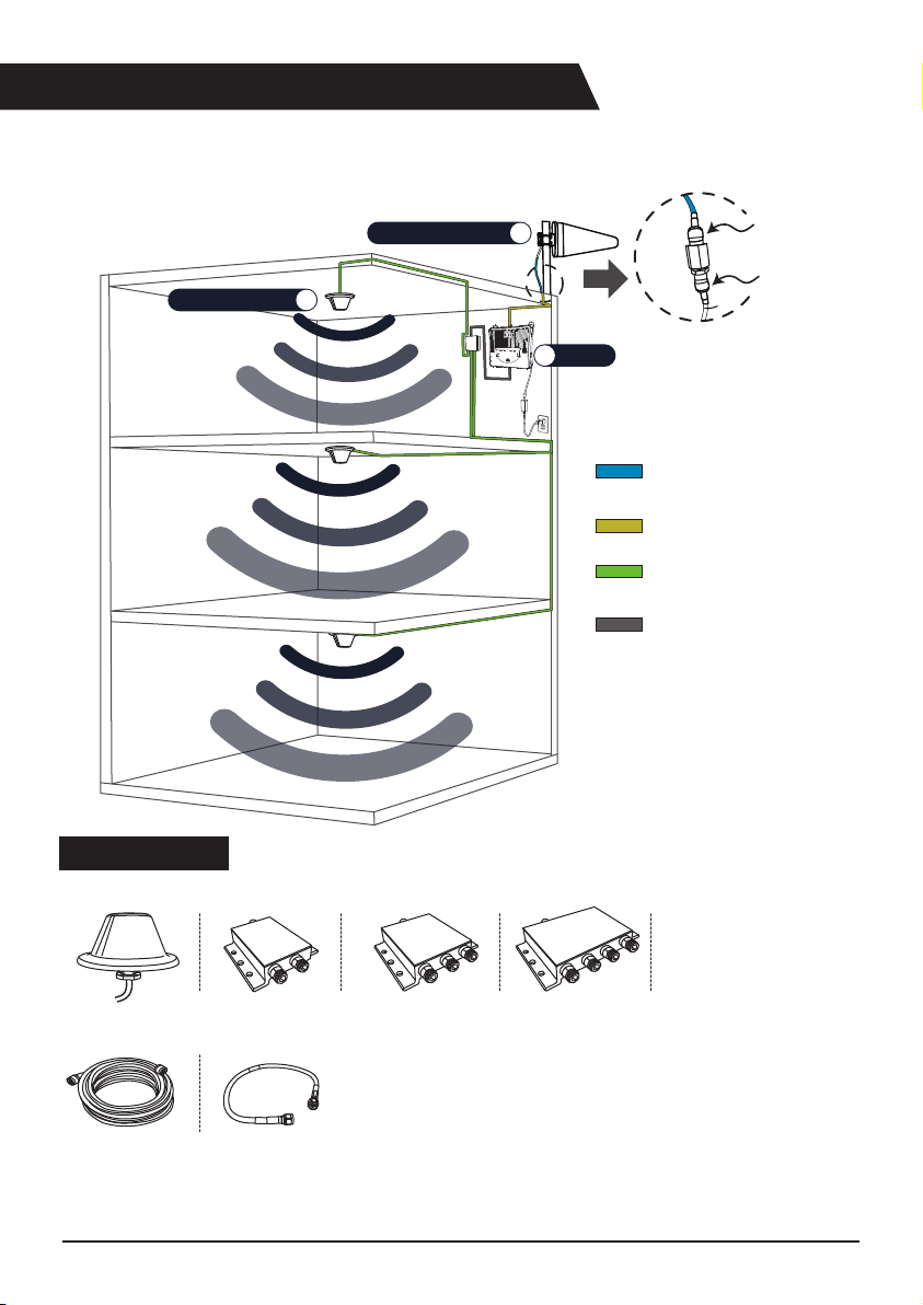
B-50K Optional Components
Optional components enable signal amplication to a further area.
Inside Antenna
Outside Antenna
3
1
2
B-50K
2 ft. Cable to
lighting protector
100 ft. Cable to
Ouside Antenna
75 ft. Cable to
Inside Antenna
2 ft. Cable to
Optional Splitter
2 ft. cable to
lighting protector
To Donor Port
Option Contents
Using multiple inside antennas for increased coverage.
Inside Antenna Kit
Code No. : 83617
Coaxial Cable 75 ft.
Code No. : 836WN
Optional Splitter
(2-Way)
Coaxial Cable 2 ft.
Code No. : 834TK
Optional Splitter
(3-Way)
B-50K User Guide
Optional Splitter
(4-Way)
7
Page 8
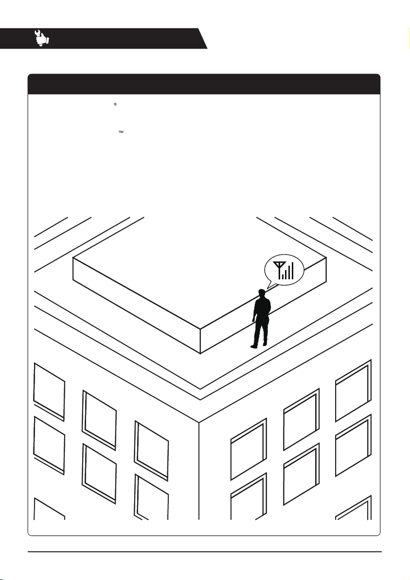
Installation Guide
STEP 1. Find the Strongest Signal
1-1. Using an iPhone
Dial *3001#12345#*, then press Call.
1-2. Using an Android
Download the ‘Network Signal info” from the Google Play store.
After installing, you will be able to view your dB strength.
1-3. Using a Meter
If you have a meter that detects and displays the current signal levels, you can use it.
8
B-50K User Guide
Page 9
STEP 1. Find the Strongest Signal
Note The stronger signal you receive from the base station, the better coverage you will have
inside your building.
-70dBm
-90dBm
B-50K User Guide
9
Page 10

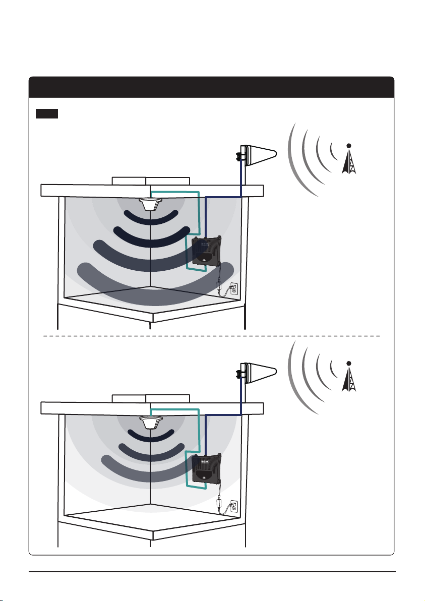
STEP 2. Install the Outside Antenna
The outside antenna must be mounted outside the building with the strongest cell signals.
Mount the outside antenna as high as possible facing towards the desired location of the
cell tower and facing the opposite direction of the expected location of the inside antenna.
Outside / Inside Antenna Separation
For the best performance, a minimum of 50 ft. distance between outside antenna and inside
antenna is recommended. The bigger the separation distance from the antenna, the higher
the coverage provided by the booster. However the smaller the separation distance, the lower
the coverage provided by the booster.
10
p
e
S
a
n
n
e
t
n
A
B-50K User Guide
.
t
f
0
5
n
o
i
t
a
r
a
Page 11

STEP 2. Install the Outside Antenna
Install the outside antenna in the location to receive the strongest signal according to the
instructions of STEP2. Make sure the outside antenna is installed facing towards the cell tower.
1
3
2
B-50K User Guide
11
Page 12

STEP 3. Run the Outside Antenna Cable
When mounting the outside antenna to the outside wall of your building, the easiest way is
to run the cable on the outside of the wall and attach it to the exterior of your oce & building.
Then drill a hole through the wall which will allow the cable to appear on the inside of the
building. To avoid any potential harm or damage, make sure that there are no electrical outlets,
sewer water pipes, or electrical wiring in the wall before drilling.
Note
TV cables already being used for other purposes can not be shared with the cell
booster during installation.
After drilling the required hole, run the cable through and seal it.
In some instances, it may be possible to run the cable up into the fascia of the attic overhang.
In this circumstance, the cable will be accessible in the attic further routing.
12
Outside Antenna
to 2 ft. cable
To Lightning Protector
To Outside Antenna
Cable (100 ft.)
B-50K User Guide
Page 13

STEP 3. Run the Outside Antenna Cable
Outside Antenna Cable
B-50K User Guide
13
Page 14

STEP 4. Install the Inside Antenna
Choose a location for the inside antennas, more advantageously at the center of where the
signal needs to be amplied.
1
2 3
14
B-50K User Guide
Page 15

1
To Inside Antenna
Cable (75 ft.)
STEP 4. Install the Inside Antenna
Outside Antenna Cable
Inside Antenna
Cable
B-50K User Guide
15
Page 16

STEP 5. Install the Signal Booster
Choose a location for the signal booster, preferably away from excessive heat, direct sunlight,
moisture and is free from high temperatures. Do not place the signal booster in an air-tight
enclosure. Attic installations may expose the booster to high heat.
16
PH(+) 3/16” × 1”
Tapping Screw
Plastic expansion bolt
B-50K User Guide
Page 17

STEP 5. Install the Signal Booster
1
3
2
From outside antenna
From inside antenna
B-50K User Guide
17
Page 18

LED
LED Status & Troubleshooting
Description LED Status Troubleshooting
Flashing Red
Status LED is green.
Input and output bars are green
Green indicates the Signal Booster
is powered, and working properly.
AC/DC adapter is damaged.
Or
AC outlet does not provide power.
Isolation between the outside and
inside antennas is being
checked now.
It will take up to 25 seconds.
Isolation between the outside and
inside antennas is good and the
Signal Booster is working properly.
No troubleshooting is required.
Verify that AC/DC adapter’s cable is
not damaged.
Or
Check if the AC outlet is working
and not controlled by a wall switch
that can cut power to the outlet.
No troubleshooting is required.
No troubleshooting is required.
18
B-50K User Guide
Page 19

Status LED is red.
Output bars are ashing green.
Flashing Red during 30 mins,
then Solid Red.
Description LED Status Troubleshooting
Outside antenna and Inside
antenna are not isolated enough
from each other.
So the Signal Booster is shutdown
at this frequency.
Uplink Signal coming from the outside
antenna to Base Station is too strong
and may cause troubles to carriers
network, so the Signal Booster stops
service at this frequency.
Signal from BTS station is too weak.
Change the position of Outside
and Inside antennas. Make sure the
Outside antenna is not facing towards
your own roof or at the inside antenna
as this will cause isolation issue and
the signal booster will stop amplifying
signals at this frequency.
Change the position of Outside
and Inside antennas. Make sure the
Outside antenna is not facing towards
your own roof or at the inside antenna
as this will cause isolation issue and
the signal booster will stop amplifying
signals at this frequency.
Change the position of Outside
antenna to receive stronger signal
from Base Station.
Outside antenna and Inside antenna
is not isolated enough from
each other.
The Signal Booster works properly.
B-50K User Guide
Change the position of Outside and
Inside antennas. Make sure the
Outside antenna is not facing towards
your own roof or at the inside
antenna as this will cause isolation
issue and the signal booster will not
be able to amplify signals at
maximum power.
19
Page 20

LED
LED Bar Display
Number of LED bars on the front side of the Signal Booster will show input and output signal
strength levels. The tables below indicate the signal strength levels.
Service band: 700MHz, 850MHz
LED Status
LED bars
Input Power LED bars Output Power
≤-81dBm
-80dBm ~ -71dBm
-70dBm ~ -61dBm
-60dBm ~ -51dBm
≥ -50dBm/Total ≥ 15dBm/Total
Service band: 1900MHz, 2100MHz
LED bars
Input Power LED bars Output Power
≤-86dBm
-85dBm ~ -76dBm
≤-16dBm
-15dBm ~ -6dBm
-5dBm ~ 4dBm
5dBm ~ 14dBm
LED Status
≤-16dBm
-15dBm ~ -6dBm
20
-75dBm ~ -66dBm
-65dBm ~ -56dBm
≥ -55dBm/Total ≥ 15dBm/Total
B-50K User Guide
-5dBm ~ 4dBm
5dBm ~ 14dBm
Page 21

Functions
ALC (Auto Level Control)
ALC maintains limit of the output power in order to protect bad inuence to the Base Station.
AGC (Auto Gain Control)
The Signal Booster checks isolation between inside and outside antennas once a day.
AGC sets up downlink and uplink gain value automatically depending on the input power level.
ASD (Auto Shutdown)
There are two cases when ASD works.
1) Outside antenna and Inside antenna are not isolated enough from each other.
So in order to protect the Signal Booster from damage, it will automatically
shutdown at this frequency.
2) Uplink Signal coming from the outside antenna to Base Station is too strong and may cause
troubles to carriers network, so the Signal Booster will shutdown at this frequency.
LED Display
Number of LED bars on the front side of the Signal Booster will show input and output signal
strength levels.
B-50K User Guide
21
Page 22

Specications
Parameter
Lower 700 MHz
Upper 700 MHz
Cellullar
Broadband PCS
AWS -1
Composite Power
Maximum Gain
Noise Figure
EVM / Spurious Emission
ANT Isolation Setting
Impedance
RF Connector
Power Connector
Power
Size, inch
Weight, lbs
Operation Temperature
Humidity
Material / Coating
Downlink Uplink Remark
704~716MHz
746~756MHz
15dBm 20dBm
65dB (700 & 850) , 70dB (1900 & 2100)
6dB nominal
3GPP & FCC Rule Complaint
Gain + 15dB @ Initialization or Recheck
50 Ohm
N-Type Female
DC-005 2ø
7.5VDC x 5.4A
10.82 x 11.61 x 2.21
8.16
14 ~ 122°F (-10°C ~ +50°C)
0 ~ 80%
AL / Flame Proof
777~787MHz
824~849MHz869~894MHz
1850~1915MHz1930~1995MHz
1710~1755MHz2110~2155MHz
Band 13 & 17734~746MHz
Band 13
Band 5
Band 25
Band 4
W × H × D
22
B-50K User Guide
Page 23

Safety Guidelines
WARNING
ELECTRIC SHOCK
Opening the Signal Booster could result in electric shock and may cause severe injury.
DAMAGE TO EQUIPMENT
Operating the Signal Booster with antennas in very close proximity facing each other could lead to
a severe damage to the Signal Booster.
Use of unauthorized antennas, cables, and/or coupling devices not conforming with ERP/EIRP and/or
indoor‐only restrictions is prohibited.
Home/ personal use are prohibited.
CAUTION
THE SIGNAL BOOSTER SHOULD BE INSTALLED AS CLOSE AS POSSIBLE TO THE POWER SOURCE.
THIS REPEATER IS FOR INDOOR USE ONLY AND SHOULD BE INSTALLED INSIDE OF THE VEHICLE.
WARNING: This is NOT a CONSUMER
device. It is designed for installation by an
installer approved by an ISED licensee.
You MUST have an ISED LICENCE or the
express consent of an ISED licensee to
operate this device.
FCC Warning Statements
FCC Part 15.105 statement
This equipment has been tested and found to comply with the limits for a Class A digital device, pursuant to part 15 of
the FCC Rules. These limits are designed to provide reasonable protection against harmful interference when the
equipment is operated in a commercial environment. This equipment generates, uses, and can radiate radio frequency
energy and, if not installed and used in accordance with the instruction manual, may cause harmful interference to radio
communications. Operation of this equipment in a residential area is likely to cause harmful interference in which case
the user will be required to correct the interference at his own expense.
FCC Part 15.21 statement
Any changes or modications not expressly approved by the party responsible for compliance could void the user's
authority to operate this equipment.
RF Exposure Statement
The antenna(s) must be installed such that a minimum separation distance of at least 20 cm is maintained between
the radiator (antenna) and all persons at all times. This device must not be co-located or operating in conjunction
with any other antenna or transmitter.
B-50K User Guide
23
Page 24

IC Warning Statements
RSS-GEN, Sec. 7.1.2 – (transmitters)
Under Industry Canada regulations, this radio transmitter may only operate using an antenna of a type and maximum
(or lesser) gain approved for the transmitter by Industry Canada. To reduce potential radio interference to other users,
the antenna type and its gain should be so chosen that the equivalent isotropically radiated power (e.i.r.p.) is not more
than that necessary for successful communication.
Conformément à la réglementation d’Industrie Canada, le présent émetteur radio peut fonctionneravec une antenne
d’un type et d’un gain maximal (ou inférieur) approuvé pour l’émetteur par Industrie Canada.
Dans le but de réduire les risques de brouillage radioélectrique à l’intention desautres utilisateurs,
il faut choisir le type d’antenne et son gain de sorte que la puissance isotroperayonnée quivalente (p.i.r.e.)
ne dépassepas l’intensité nécessaire à l’établissement d’une communication satisfaisante.
RSS-GEN, Sec. 7.1.2 – (detachable antennas)
This radio transmitter (identify the device by certication number, or model number if Category II)has been approved
by Industry Canada to operate with the antenna types listed below with the maximum permissible gain and required
antenna impedance for each antenna type indicated. Antenna types not included in this list, having a gain greater than
the maximum gain indicated for that type, are strictly prohibited for use with this device.
Le présent émetteur radio (identier le dispositif par son numéro de certication ou son numéro de modèle s’il fait
partie du matériel de catégorie I) a été approuvé par Industrie Canada pour fonctionner avec les types d’antenne
énumérés ci-dessous et ayant un gain admissible maximal et l’impédance requise pour chaque type d’antenne.
Les types d’antenne non inclus dans cette liste,ou dont le gain est supérieur au gain maximal indiqué, sont strictement
interdits pour l’exploitation de l’émetteur.
RF Radiation Exposure
This equipment complies with RF radiation exposure limits set forth for an uncontrolled environment. This equipment
should be installed and operated with a minimum distance of 50 cm between the radiator and your body.
This transmitter must not be co-located or operating in conjunction with any other antenna or transmitter.
RF exposure will be addressed at time of installation and the use of higher gain antennas require larger separation
distances.
RSS-102 RF Exposure
L’antenne (ou les antennes) doit être installée de façon à maintenir à tout instant une distance minimum de au moins
50 cm entre la source de radiation (l’antenne) et toute personne physique. Cet appareil ne doit pas être installé ou
utilisé en conjonction avec une autre antenne ou émetteur.
24
B-50K User Guide
Page 25

WARRANTY
Opening or tampering with the Signal Booster will void all warranties.
American Booster provides a 3-year warranty for B-50K with all of its equipment.
Every product of American Booster is guaranteed to be free of material defects or component
malfunctions.
This warranty does not cover to any Signal Boosters that have been exposed to any misuse, abuse,
physical damage or inadequate maintenance.
Products returned by customers must be in their original, unmodied condition, shipped in the
original packaging with proof of purchase documentation enclosed, and a Return Merchandise
Authorization (RMA) number printed on the outside of the shipping box.
To repair or replace damaged Signal Boosters we may include refurbished American Booster’s products.
130 E Covey Run, Union, WA 98592
Technical Support : 913 469 6699 www.americanbst.com
B-50K User Guide
25
Page 26

Memo
26
B-50K User Guide
Page 27

Memo
B-50K User Guide
27
Page 28

www.americanbst.com
Technical Support : 913 469 6699
B-50K User Guide
 Loading...