

Page 1
PNEG-1807CE
CE Compliant 16"-24" Bucket
Elevator Platform and Ladder
“X” Series
Installation Manual - Original Instructions
PNEG-1807CE
Date: 05-16-14
Page 2

Use of the equipment information page will help you identify the equipment in the case that you need to
call your dealer or installer. This information should be filled out and kept on record.
Equipment Information
Model #:___________________________________________
Serial #:____________________________________
Date Purchased:____________________________________
Dealer/Distributor Name and Phone #:___________________________________________
Material Handling
1004 E. Illinois St.
Assumption, IL. 62510
Phone: 1-217-226-4421
2 PNEG-1807CE CE Compliant 16"-24" Bucket Elevator Platform and Ladder “X” Series
Page 3

Table of Contents
Contents
Chapter 1 Introduction .......................................................................................................................................... 4
Chapter 2 Safety ..................................................................................................................................................... 5
Safety Guidelines .................................................................................................................................. 5
Safety Instructions ..................... ... .... .......................................... ... ... ..................................................... 6
Chapter 3 Decal Location ...................................................................................................................................... 8
Chapter 4 Overview ............................................................................................................................................... 9
Chapter 5 Ladder Assembly ............................................................................................................................... 10
Typical Ladder/Cage Setup ................................................................................................................. 18
Chapter 6 Tie Angles, Ladder Brackets and Safety Cages .............................................................................. 19
Attach Tie Angle to Boot Trunking ................................................ ... ... ... .... ... ... ... .... ... ... ... ... .... ...... ... ... 19
Attach Boot Ladder Support Brackets and Boot Ladder Section ........................................................ 20
Install Boot Ladder Section ................................................................................................................. 22
Tie Angles to Trunking ........... ... ... .... ... ... ... ... .......................................... .... ... ... ... .... ... ......................... 24
Ladder Support Brackets .................................................................................................................... 27
Attach Ladders to Ladder Brackets ............................... ... ... ... .... ... ... .......................................... ...... ... 30
Safety Cage Installation ......... ... ... .... ... .......................................... ... ... ... .... ... ... ... .... ... ... ... .......... ... ... ... 31
Install Safety Cage .............................................................................................................................. 32
Chapter 7 Rest Platform ...................................................................................................................................... 35
Rest Platform Tie Angles to Bucket Elevators .................................................................................... 35
Attach Rest Platform Channel to the Rest Platform Tie Angle ............................ .... ... ... ... ... .... ... ... ... ... 38
Rest Platform Cross Channel to Rest Platform Mounting Channels ................................................... 39
Ladder Support ................................................................................................................................... 44
Chapter 8 16"-24" Head Platform Assembly ..................................................................................................... 45
Attach Main Support Channels to Lower Head ................................... ... .... ... ... ... .... ... ... ... ................... 45
Install Deck A and Toe Board ............................................................................................................. 46
Install Deck A to Main Support Channels ............................................................................................ 47
Install Deck C and Toe Board ............................................................................................................. 49
Install Deck C to Main Support Channels ........................................................................................... 50
Install Deck E ...................................................................................................................................... 51
Install Adapter Bracket for 16" Platforms ............................................................................................ 53
Install Hatch Filler Plate ...................................................................................................................... 54
Install Rail Supports to Deck E ......................... ... ... ... .... ... ... ... .... ... ... ... ... .... ... ...................................... 54
Install “W” Posts (“Corner Posts” x 4) ................................................................................................. 55
Install Platform Posts .......................................................................................................................... 56
Install Intermediate Handrails .............................................................................................................. 58
Install Upper Handrails ........................................................................................................................ 60
Install Tie Braces (Safety Cage Bars) ................................................................................................. 61
Chapter 9 Install Hatch ........................................................................................................................................ 62
Chapter 10 4 x 5 Distributor Platform (Optional) .............................................................................................. 65
16"-24" Clamp Band Installation ........................................................................................................ 65
Assemble Supports (16"-24") ............................................................................................................ 69
Assemble Decking and “W” Corner Post .............................. ................................................. ............ 71
Install Handrail Posts - Non Entrance Side ....................................................................................... 73
Install Intermediate Handrails ............................................................................................................ 75
Install Safety Bar Cross Supports ...................................................................................................... 76
Install Top Handrails .......................................................................................................................... 77
Safety Gate Package (Optional) ........................................................................................................ 78
Chapter 11 Warranty ............................................................................................................................................ 79
PNEG-1807CE CE Compliant 16"-24" Bucket Elevator Platform and Ladder “X” Series 3
Page 4

1. Introduction
Chapter 1: Introduction
READ THIS MANUAL carefully to learn how to properly use and install equipment. Failure to do so could
result in personal injury or equipment damage.
INSPECT the shipment immediately upon arrival. The customer is responsible for ensuring that all
quantities are correct. The customer should report and note any damage or shortage on the bill of
lading to justify their claim to the transport company.
THIS MANUAL SHOULD BE CONSIDERED a permanent part of your equipment and should be easily
accessible when needed.
This warranty provides you the assurance that the company will back its products when defects appear
within the warranty period. In some circumstances, the company also provides field improvements, often
without charge to the customer, even if the product is out of warranty. Should the equipment be abused,
or modified to change its performance beyond the factory specifications, the warranty will become void
and field improvements may be denied.
4 PNEG-1807CE CE Compliant 16"-24" Bucket Elevator Platform and Ladder “X” Series
Page 5
2. Safety
DANGER
WARNING
CAUTION
NOTICE
This is the safety alert symbol. It is used to alert you
to potential personal injury hazards. Obey all safety
messages that follow this symbol to avoid possible
injury or death.
WARNING indicates a hazardous situation which, if not
avoided, could result in death or serious injury.
CAUTION, used with the safety alert symbol, indicates a
hazardous situation which, if not avoided, could result in
minor or moderate injury.
NOTICE is used to address practices not related to
personal injury.
DANGER indicates a hazardous situation which, if not
avoided, will result in death or serious injury.
Chapter 2: Safety
Safety Guidelines
This manual contains information that is important for you, the owner/operator, to know and understand.
This information relates to protecting personal safety and preventing equipment problems. It is the
responsibility of the owner/operator to inform anyone operating or working in the area of this equipment
of these safety guidelines. To help you recognize this information, we use the symbols that are defined
below. Please read the manual and pay attention to these sections. Failure to read this manual and its
safety instructions is a misuse of the equipment and may lead to serious injury or death.
PNEG-1807CE CE Compliant 16"-24" Bucket Elevator Platform and Ladder “X” Series 5
Page 6
2. Safety
Follow Safety Instructions
Carefully read all safety messages in this manual and
safety signs on your machine. Keep signs in good
condition. Replace missing or damaged safety signs. Be
sure new equipment components and repair parts include
the current safety signs. Replacement safety signs are
available from the manufacturer.
Learn how to operate the machine and how to use controls
properly. Do not let anyone operate without instruction.
Keep your machinery in proper working condition.
Unauthorized modifications to the machine may impair
the function and/or safety and affect machine life.
If you do not understand any part of this manual or need
assistance, contact your dealer.
Read and Understand Manual
Practice Safe Maintenance
Understand service procedures before doing work. Keep area
clean and dry.
Never lubricate, service, or adjust machine while it is in operation.
Keep hands, feet, and clothing away from rotating parts.
Keep all parts in good condition and properly installed. Fix
damage immediately. Replace worn or broken parts. Remove any
built-up grease, oil, and debris.
Maintain Equipment
and Work Area
Safety Instructions
Our foremost concern is your safety and the safety of others associated with this equipment. We want to
keep you as a customer. This manual is to help you understand safe operating procedures and some
problems that may be encountered by the operator and other personnel.
As owner and/or operator, it is your responsibility to know what requirements, hazards, and precautions
exist, and to inform all personnel associated with the equipment or in the area . Safety precautions may be
required from the personnel. Avoid any alterations to the equipment. Such alterations may produce a very
dangerous situation where SERIOUS INJURY or DEATH may occur.
This equipment shall be installed in accordance with the current installation codes and applicable
regulations, which should be carefully followed in all cases. Authorities having jurisdiction should be
consulted before installations are made.
6 PNEG-1807CE CE Compliant 16"-24" Bucket Elevator Platform and Ladder “X” Series
Page 7
2. Safety
Prepare for Emergencies
Be prepared if fire starts.
Keep a first aid kit and fire extinguisher handy.
Keep emergency numbers for doctors, ambulance service,
hospital, and fire department near your telephone.
Keep Emergency Equipment
Quickly Accessible
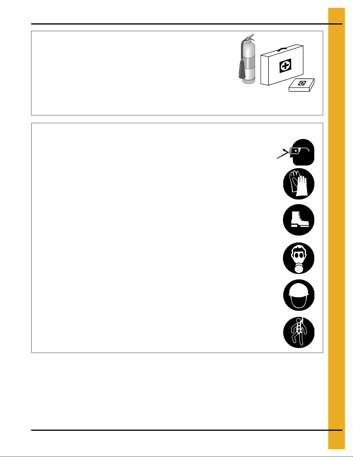
Wear Protective Clothing
Wear close-fitting clothing and safety equipment appropriate
to the job.
Remove all jewelry.
Tie long hair up and back.
Wear safety glasses at all times to protect eyes from debris.
Wear gloves to protect your hands from sharp edges on
plastic or steel parts.
Wear steel-toed boots to help protect your feet from falling
debris. Tuck in any loose or dangling shoestrings.
A respirator may be needed to prevent breathing potentially
toxic fumes and dust.
Wear a hard hat to help protect your head.
Wear appropriate fall protection equipment when working at
elevations greater than six feet (6').
Eye Protection
Gloves
Steel-Toed Boots
Respirator
Hard Hat
Fall Protection
PNEG-1807CE CE Compliant 16"-24" Bucket Elevator Platform and Ladder “X” Series 7
Page 8
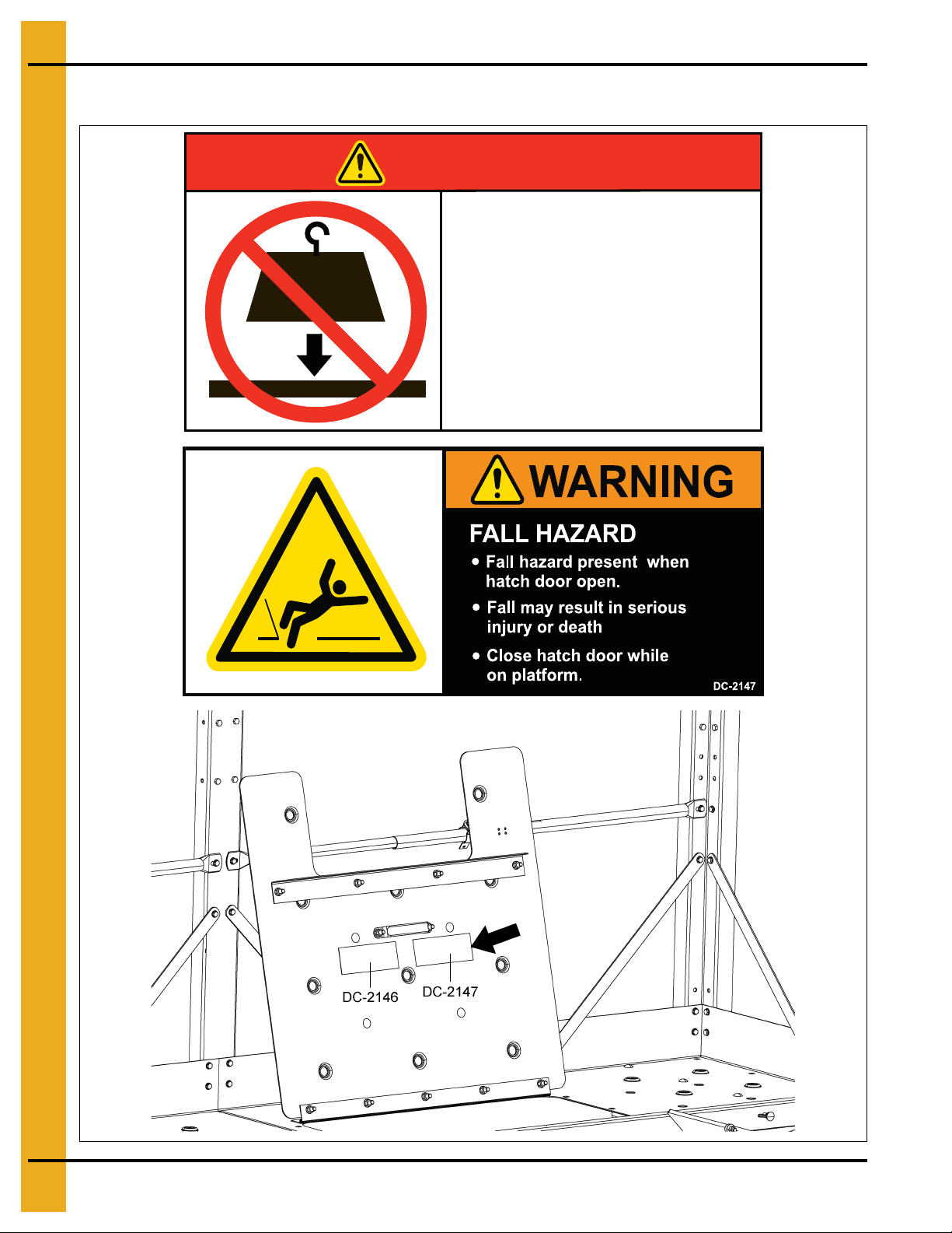
3. Decal Location
DO NOT EXCEED
PLATFORM LOAD LIMIT
DC-2146
Excessive load will damage
platform and cause
platform to fall.
Load limit = 500 LBS. (2.25 kN)
DANGER
> 500 lbs
(2.25 kN)
Injury or death will result.
Chapter 3: Decal Location
8 PNEG-1807CE CE Compliant 16"-24" Bucket Elevator Platform and Ladder “X” Series
Page 9

4. Overview
Chapter 4: Overview
This section is intended to provide a general, high-level overview of platform assembly for your GSI bucket
elevator. Detailed instructions are given in the pages to come.
This section should be used for reference only and is intended to provide general guidance about the
overall process only.
1. Support Channels:
Proper orientation of channels is based upon the size of the bucket elevator (16", 24", 30" or 36")
AND the right/left hand position of the drive. This must be installed correctly at the start or nothing
else will install correctly.
2. Ladders and Safety Cages:
Ladder sections mount directly to the trunking sections of the bucket elevator. Typical lad der layouts
and charts identifying the support height for ladder packages can be fou nd on Pages 10 through 16.
3. Tie Angles to Trunking:
• Proper orientation of the tie angles is critical for correct installation.
• Note differences from up-leg and down-leg installations.
Be sure to follow the instructions for the size and drive position.
Throughout this manual, particular attention is given to the initial orientation of channels and aligning
bolt holes. Failure to complete these initial steps correctly will significantly impede the assembly and
installation of the bucket elevator platforms.
4. Decking and Toe Boards:
Decking is etched with alpha characters to assist with orienting decks and aligning holes for
connections. Decking connections should be finger-tight only initially so that adjustments can be
made once all decks and toe boards are in place. Only then should all hardware be fully torqued.
5. Handrail Platform Posts:
The number and location of platform posts varies based upon platform and bucket elevator size.
6. Handrails:
Intermediate handrails (those at near knee level) may need to be field cut to fit. The amount to trim
varies based upon the size of the platform being installed. The smaller rail then fits inside of the larger
rail so that it “telescopes” between the posts. Always follow best practices of “measure twice cut
once” and verify the measurement is for the bucket elevator size. Upper handrails do not req uire any
alterations in the field prior to assembly.
7. Platform Braces:
Throughout this manual, safety cage bars (LDR-517BE) are used as platform braces. These are
required for support and stability. Please attach as described through the manual.
PNEG-1807CE CE Compliant 16"-24" Bucket Elevator Platform and Ladder “X” Series 9
Page 10
5. Ladder Assembly
14' (4.26 m)
Section
14' (4.26 m)
Section
10' (3.0 m)
Section
14' (4.26 m)
Section
10' (3.0 m)
Section
50'
40'
30'
HP
1636XRLAD30CE
1636XWLAD30CE
1636XRLAD40CE
1636XWLAD40CE
1636XRLAD50CE
1636XWLAD50CE
RP
RPRPHP
HP
Key: HP = Head Platform
RP = Rest Platform
10' (3.0 m)
Section
10' (3.0 m)
Section
10' (3.0 m)
Section
10' (3.0 m)
Section
14' (4.26 m)
Section
14' (4.26 m)
Section
14' (4.26 m)
Section
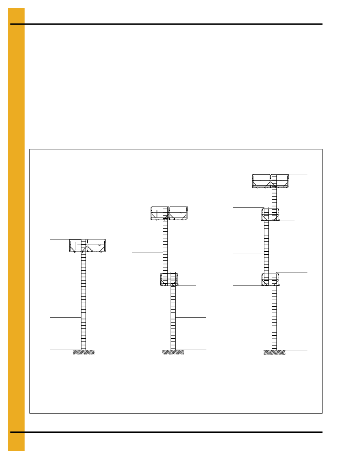
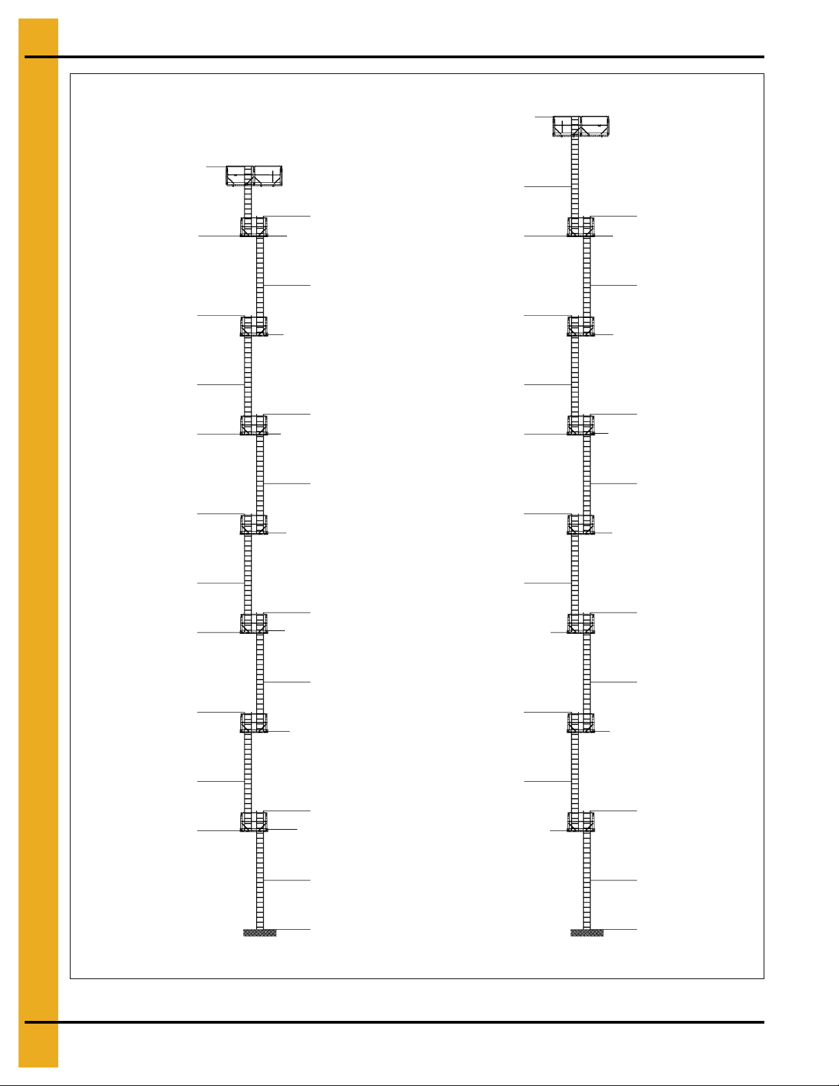
Chapter 5: Ladder Assembly
The ladder sections are to be mounted directly to the trunking sections. Quantities and section lengths
may vary depending on overall height of system. If you have a non-standard height system, refer to
supported bucket height reference chart for the correct ladder package for the system.
NOTE: Ladders are of a modular design for ease of modification in the field. These illustrations are only
to be used as a “general” guide to installation layout. The exact assembly may vary due to the
unique nature of each bucket elevator.
Ladder and Platform Layout for European CE Compliance
To comply with European Directives for CE marking, the maximum rest platform spacing is reduced,
in accordance with EN ISO14122-4:2004. Please follow the recommended layouts given below.
(See Figures 5A-5G on Pages 10-16.)
Figure 5A
10 PNEG-1807CE CE Compliant 16"-24" Bucket Elevator Platform and Ladder “X” Series
Page 11
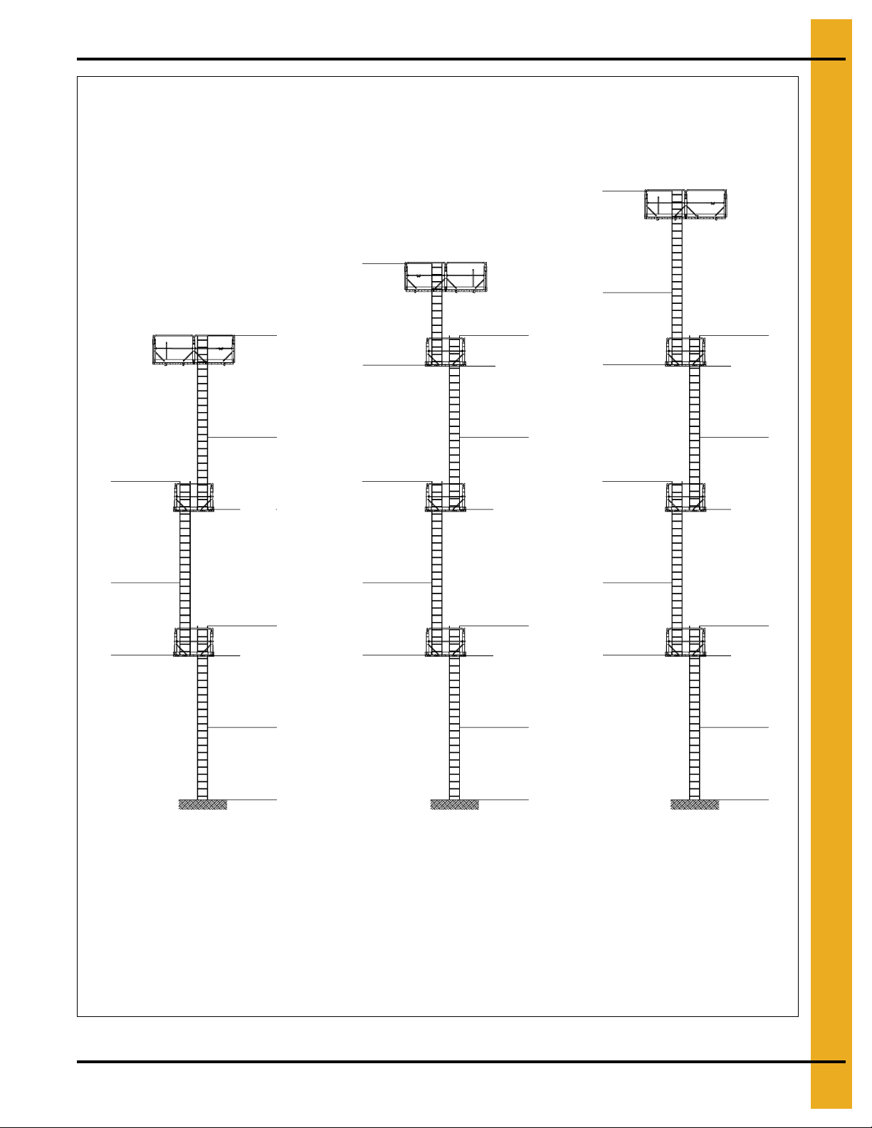
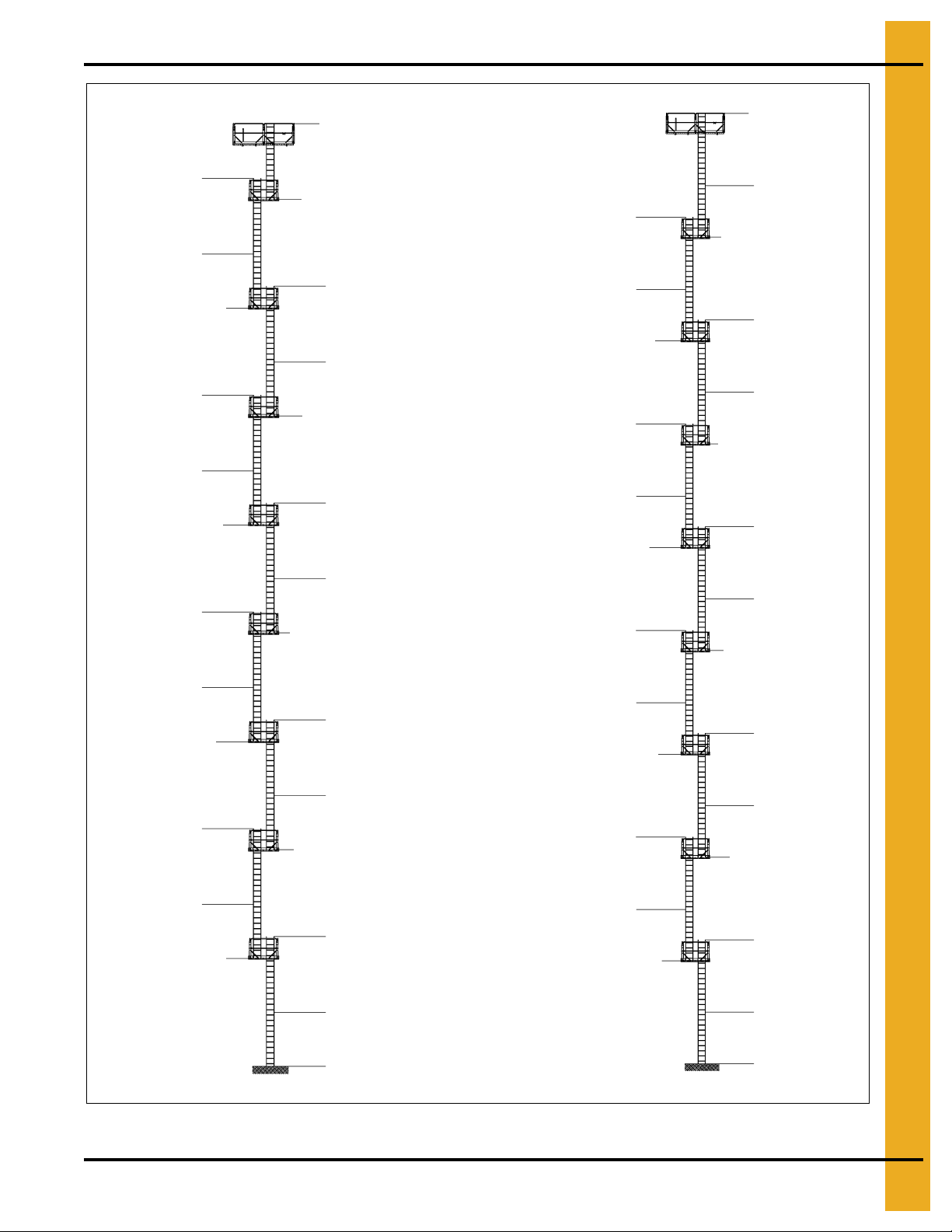
5. Ladder Assembly
14' (4.26 m)
Section
14' (4.26 m)
Section
80'
70'
60'
14' (4.26 m)
Section
14' (4.26 m)
Section
14' (4.26 m)
Section
14' (4.26 m)
Section
1636XRLAD60CE
1636XWLAD60CE
1636XRLAD70CE
1636XWLAD70CE
1636XRLAD80CE
1636XWLAD80CE
RPRPRPRPRPRPRP
RP
HP
HP
HP
Key: HP = Head Platform
RP = Rest Platform
10' (3.0 m)
Section
14' (4.26 m)
Section
10' (3.0 m)
Section
10' (3.0 m)
Section
14' (4.26 m)
Section
10' (3.0 m)
Section
10' (3.0 m)
Section
14' (4.26 m)
Section
10' (3.0 m)
Section
10' (3.0 m)
Section
14' (4.26 m)
Section
10' (3.0 m)
Section
10' (3.0 m)
Section
14' (4.26 m)
Section
10' (3.0 m)
Section
PNEG-1807CE CE Compliant 16"-24" Bucket Elevator Platform and Ladder “X” Series 11
Figure 5B
Page 12

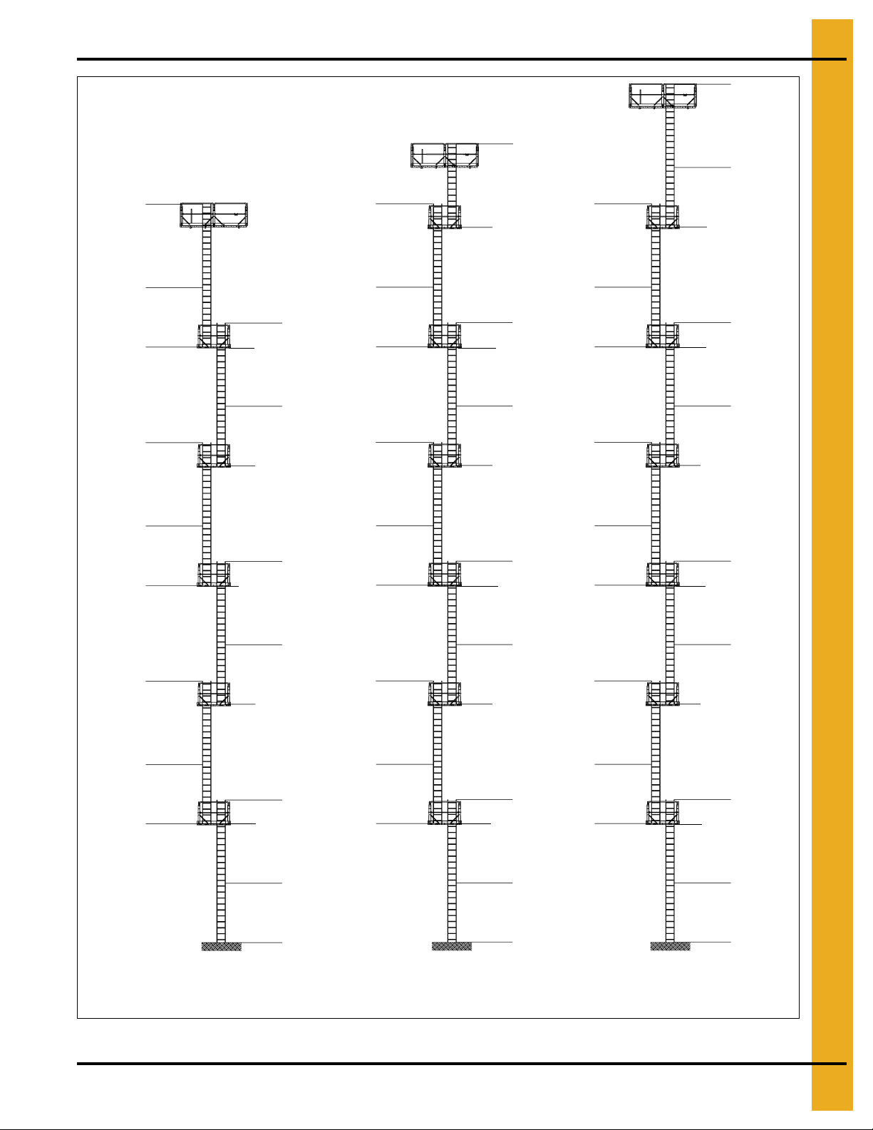
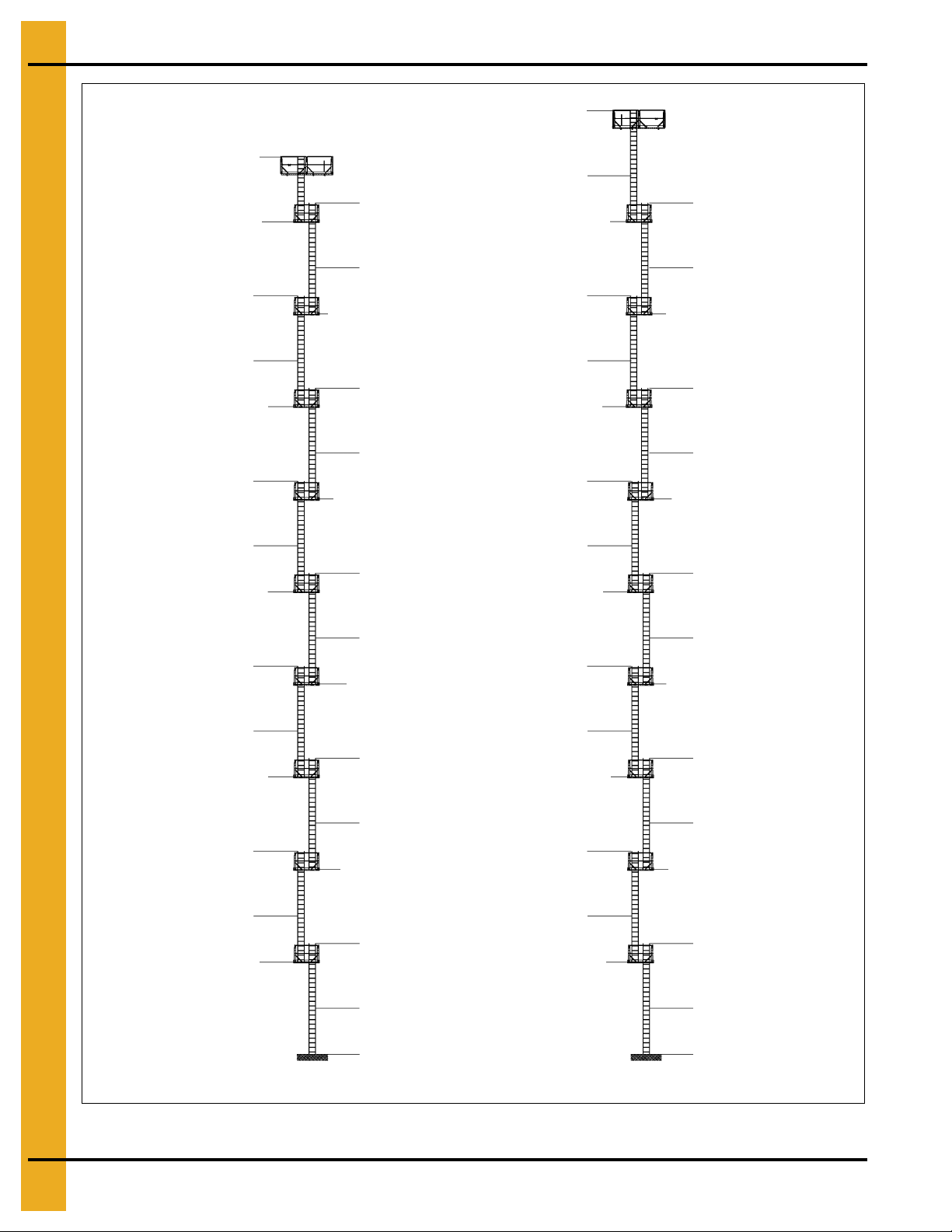
5. Ladder Assembly
14' (4.26 m)
Section
14' (4.26 m)
Section
14' (4.26 m)
Section
14' (4.26 m)
Section
90'
14' (4.26 m)
Section
14' (4.26 m)
Section
14' (4.26 m)
Section
100'
110'
10' (3.0 m)
Section
14' (4.26 m)
Section
14' (4.26 m)
Section
10' (3.0 m)
Section
14' (4.26 m)
Section
10' (3.0 m)
Section
14' (4.26 m)
Section
10' (3.0 m)
Section
10' (3.0 m)
Section
10' (3.0 m)
Section
14' (4.26 m)
Section
10' (3.0 m)
Section
14' (4.26 m)
Section
10' (3.0 m)
Section
10' (3.0 m)
Section
10' (3.0 m)
Section
10' (3.0 m)
Section
1636XRLAD90CE
1636XWLAD90CE
1636XRLAD100CE
1636XWLAD100CE
1636XRLAD110CE
1636XWLAD110CE
RP
RPRPRP
RPRPRP
RP
RPRPRP
RP
Key: HP = Head Platform
RP = Rest Platform
HP
HP
HP
14' (4.26 m)
Section
10' (3.0 m)
Section
14' (4.26 m)
Section
10' (3.0 m)
Section
14' (4.26 m)
Section
10' (3.0 m)
Section
RP
Figure 5C
12 PNEG-1807CE CE Compliant 16"-24" Bucket Elevator Platform and Ladder “X” Series
Page 13
5. Ladder Assembly
14' (4.26 m)
Section
14' (4.26 m)
Section
120'
14' (4.26 m)
Section
14' (4.26 m)
Section
130'
140'
10' (3.0 m)
Section
14' (4.26 m)
Section
10' (3.0 m)
Section
14' (4.26 m)
Section
10' (3.0 m)
Section
14' (4.26 m)
Section
10' (3.0 m)
Section
14' (4.26 m)
Section
10' (3.0 m)
Section
10' (3.0 m)
Section
14' (4.26 m)
Section
14' (4.26 m)
Section
10' (3.0 m)
Section
14' (4.26 m)
Section
10' (3.0 m)
Section
10' (3.0 m)
Section
14' (4.26 m)
Section
10' (3.0 m)
Section
14' (4.26 m)
Section
10' (3.0 m)
Section
14' (4.26 m)
Section
10' (3.0 m)
Section
10' (3.0 m)
Section
14' (4.26 m)
Section
10' (3.0 m)
Section
14' (4.26 m)
Section
10' (3.0 m)
Section
14' (4.26 m)
Section
10' (3.0 m)
Section
10' (3.0 m)
Section
14' (4.26 m)
Section
10' (3.0 m)
Section
14' (4.26 m)
Section
10' (3.0 m)
Section
RP
RP
RPRPRP
RPRPRPRPRPRPRP
1636XRLAD120CE
1636XWLAD120CE
1636XRLAD130CE
1636XWLAD130CE
1636XRLAD140CE
1636XWLAD140CE
RP
RPRPRP
RP
HPHPHP
Key: HP = Head Platform
RP = Rest Platform
14' (4.26 m)
Section
PNEG-1807CE CE Compliant 16"-24" Bucket Elevator Platform and Ladder “X” Series 13
Figure 5D
Page 14
5. Ladder Assembly
150'
14' (4.26 m)
Section
160'
14' (4.26 m)
Section
10' (3.0 m)
Section
14' (4.26 m)
Section
10' (3.0 m)
Section
14' (4.26 m)
Section
10' (3.0 m)
Section
14' (4.26 m)
Section
10' (3.0 m)
Section
14' (4.26 m)
Section
10' (3.0 m)
Section
14' (4.26 m)
Section
10' (3.0 m)
Section
10' (3.0 m)
Section
14' (4.26 m)
Section
10' (3.0 m)
Section
1636XRLAD150CE
1636XWLAD150CE
RP
RP
RP
1636XRLAD160CE
1636XWLAD160CE
RP
Key: HP = Head Platform
RP = Rest Platform
RPRPRP
14' (4.26 m)
Section
10' (3.0 m)
Section
RP
14' (4.26 m)
Section
10' (3.0 m)
Section
RP
14' (4.26 m)
Section
10' (3.0 m)
Section
RP
14' (4.26 m)
Section
10' (3.0 m)
Section
RP
14' (4.26 m)
Section
10' (3.0 m)
Section
14' (4.26 m)
Section
10' (3.0 m)
Section
10' (3.0 m)
Section
14' (4.26 m)
Section
RP
10' (3.0 m)
Section
14' (4.26 m)
Section
RP
RPHPHP
Figure 5E
14 PNEG-1807CE CE Compliant 16"-24" Bucket Elevator Platform and Ladder “X” Series
Page 15
5. Ladder Assembly
180'
1636XRLAD180CE
1636XWLAD180CE
180'
1636XRLAD170CE
1636XWLAD170CE
170'
10' (3.0 m)
Section
14' (4.26 m)
Section
RP
10' (3.0 m)
Section
14' (4.26 m)
Section
10' (3.0 m)
Section
14' (4.26 m)
Section
10' (3.0 m)
Section
14' (4.26 m)
Section
10' (3.0 m)
Section
14' (4.26 m)
Section
10' (3.0 m)
Section
14' (4.26 m)
Section
10' (3.0 m)
Section
14' (4.26 m)
Section
10' (3.0 m)
Section
14' (4.26 m)
Section
14' (4.26 m)
Section
RP
RP
RPRPRP
RP
RP
10' (3.0 m)
Section
14' (4.26 m)
Section
10' (3.0 m)
Section
14' (4.26 m)
Section
10' (3.0 m)
Section
14' (4.26 m)
Section
10' (3.0 m)
Section
14' (4.26 m)
Section
10' (3.0 m)
Section
14' (4.26 m)
Section
10' (3.0 m)
Section
14' (4.26 m)
Section
10' (3.0 m)
Section
14' (4.26 m)
Section
10' (3.0 m)
Section
14' (4.26 m)
Section
10' (3.0 m)
Section
14' (4.26 m)
Section
RP
RPRPRP
RP
RPRPRP
Key: HP = Head Platform
RP = Rest Platform
HP
HP
PNEG-1807CE CE Compliant 16"-24" Bucket Elevator Platform and Ladder “X” Series 15
Figure 5F
Page 16
5. Ladder Assembly
190'
200'
10' (3.0 m)
Section
14' (4.26 m)
Section
10' (3.0 m)
Section
14' (4.26 m)
Section
10' (3.0 m)
Section
14' (4.26 m)
Section
10' (3.0 m)
Section
14' (4.26 m)
Section
10' (3.0 m)
Section
14' (4.26 m)
Section
10' (3.0 m)
Section
14' (4.26 m)
Section
14' (4.26 m)
Section
10' (3.0 m)
Section
14' (4.26 m)
Section
10' (3.0 m)
Section
14' (4.26 m)
Section
10' (3.0 m)
Section
14' (4.26 m)
Section
RPRPRP
RP
RP
RP
RP
1636XRLAD200CE
1636XWLAD200CE
10' (3.0 m)
Section
14' (4.26 m)
Section
10' (3.0 m)
Section
14' (4.26 m)
Section
10' (3.0 m)
Section
14' (4.26 m)
Section
10' (3.0 m)
Section
14' (4.26 m)
Section
10' (3.0 m)
Section
14' (4.26 m)
Section
10' (3.0 m)
Section
14' (4.26 m)
Section
10' (3.0 m)
Section
14' (4.26 m)
Section
10' (3.0 m)
Section
14' (4.26 m)
Section
10' (3.0 m)
Section
14' (4.26 m)
Section
10' (3.0 m)
Section
14' (4.26 m)
Section
RPRPRPRPRPRPRPRPRP
Key: HP = Head Platform
RP = Rest Platform
HP
HP
RP
RP
1636XRLAD190CE
1636XWLAD190CE
Figure 5G
16 PNEG-1807CE CE Compliant 16"-24" Bucket Elevator Platform and Ladder “X” Series
Page 17
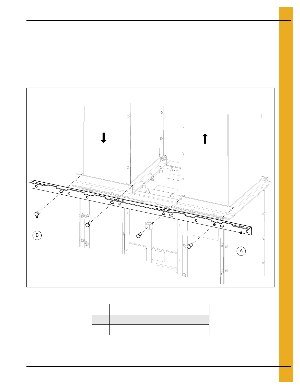
6. Tie Angles, Ladder Brackets and Safety Cages
Down-leg
Up-leg
16" Boot Tie Angle
Chapter 6: Tie Angles, Ladder Brackets and Safety Cages
Attach Tie Angle to Boot Trunking
1. On the NON-LADDER SIDE, attach tie angle to the trunking using 1/2" x 1" bolts.
below and
a. For 16" Boot Tie Angle: With lip of tie angle up and outward, align tie angle so that it extends
beyond the trunking at each end. (See Figure 6A.)
Figure 6B on Page 18.)
(See Figure 6A
PNEG-1807CE CE Compliant 16"-24" Bucket Elevator Platform and Ladder “X” Series 17
Figure 6A 16" Boot Tie Angle
Ref # Part # Description
A BECT1640FX Type “X” Tie Angle
B S-7935 12" x 1" Bolt
Page 18
6. Tie Angles, Ladder Brackets and Safety Cages
Down-leg
Up-leg
24" Boot Tie Angle
Attach Tie Angle to Boot Trunking (Continued)
b. For 24" Boot Tie Angle: With lip of tie angle up and outward, align edge of tie angle to edge
of trunking at down-leg end. With this alignment, tie angle will extend slightly beyond the edge of
trunking at the up-leg end, as shown in Figure 6B.
Figure 6B 24" Boot Tie Angle
Ref # Part # Description
A BECT1640FX Type “X” Tie Angle
B S-7935 12" x 1" Bolt
18 PNEG-1807CE CE Compliant 16"-24" Bucket Elevator Platform and Ladder “X” Series
Page 19
6. Tie Angles, Ladder Brackets and Safety Cages
Down-leg
Up-leg
16" Boot Bracket Down-Leg
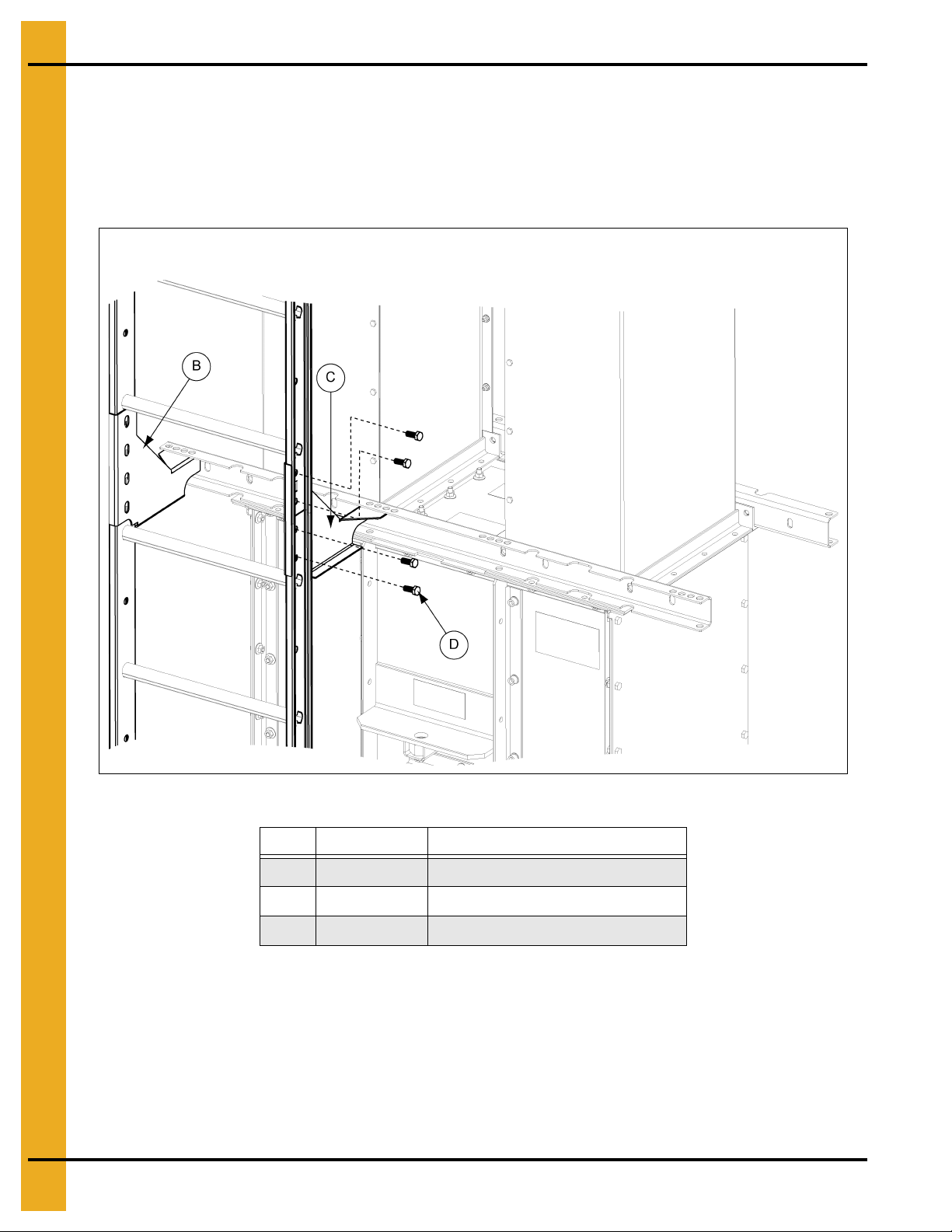
Attach Boot Ladder Support Brackets and Boot Ladder Section
NOTE: Refer to ladder layout images, Figure 5A-5G on Pages 10-16.
NOTE: Ladders can be mounted to either the up-leg or down-leg end of the elevator depending on the
height and head platform hatch location.
NOTE: Both up-leg and down-leg bracket locations are shown in this manual. Actual installation location
on either the up-leg or down-leg will be determined by owner preference.
1. Using the holes indicated based on bucket elevator size in Figure 6C, attach ladder support brackets
to boot tie angle using 3/8" x 1" hex bolts. Remember to double check if the ladder should start on
the up-leg side or the down-leg side. (See Figures 6C-6H on Pages 19-24.)
a. 16" Down-leg boot bracket: Use 3/8 " x 1" hex bolts to attach the ladder support brackets to the
boot tie angle using the holes indicated in Figure 6C. Note the outer bracket uses the outer most
holes of the tie angle and the inner bracket will have two (2) empty holes beside it on the tie angle.
PNEG-1807CE CE Compliant 16"-24" Bucket Elevator Platform and Ladder “X” Series 19
Figure 6C 16" Boot Bracket Down-Leg
Ref # Part # Description
A LAD1648TRH R.H. Side Trunk Support Bracket
B LAD1648TLH L.H. Side Trunk Support Bracket
C S-7469 3/8" x 1" Hex Bolt
Page 20
6. Tie Angles, Ladder Brackets and Safety Cages
Down-leg
Up-leg
16" Boot Bracket Up-Leg
Attach Boot Ladder Support Brackets and Boot Ladder
Section (Continued)
b. 16" Up-leg boot bracket: Use 3/8" x 1" hex bolts to attach the ladder support brackets to the
boot tie angle using the holes indicated in Figure 6D. Note the outer bracket attaches to the tie
angle with two (2) empty holes remain on the outside.
Figure 6D 16" Boot Bracket Up-Leg
Ref # Part # Description
C S-7469 3/8" x 1" Hex Bolt
20 PNEG-1807CE CE Compliant 16"-24" Bucket Elevator Platform and Ladder “X” Series
Page 21
6. Tie Angles, Ladder Brackets and Safety Cages
Down-leg
Up-leg
24" Boot Bracket Down-Leg
Attach Boot Ladder Support Brackets and Boot Ladder
Section (Continued)
c. 24" Down-leg boot bracket: Use 3/8" x 1" h ex bolts to attach the ladder support brackets to the
boot tie angle using the holes indicated in Figure 6E. Note the outer bracket will have two (2)
empty holes to the outside of the connection at the tie angle.
Figure 6E 24" Boot Bracket Down-Leg
Ref # Part # Description
C S-7469 3/8" x 1" Hex Bolt
PNEG-1807CE CE Compliant 16"-24" Bucket Elevator Platform and Ladder “X” Series 21
Page 22
6. Tie Angles, Ladder Brackets and Safety Cages
Down-leg
Up-leg
24" Boot Bracket Up-Leg
Attach Boot Ladder Support Brackets and Boot Ladder
Section (Continued)
d. 24" Up-leg boot bracket: Use 3/8" x 1" hex bolts to attach the ladder support brackets to the
boot tie angle using the holes indicated in Figure 6F. Note the outer bracket uses the two (2)
outer most set of holes on the tie angle.
Figure 6F 24" Boot Bracket Up-Leg
Ref # Part # Description
C S-7469 3/8" x 1" Hex Bolt
22 PNEG-1807CE CE Compliant 16"-24" Bucket Elevator Platform and Ladder “X” Series
Page 23
6. Tie Angles, Ladder Brackets and Safety Cages
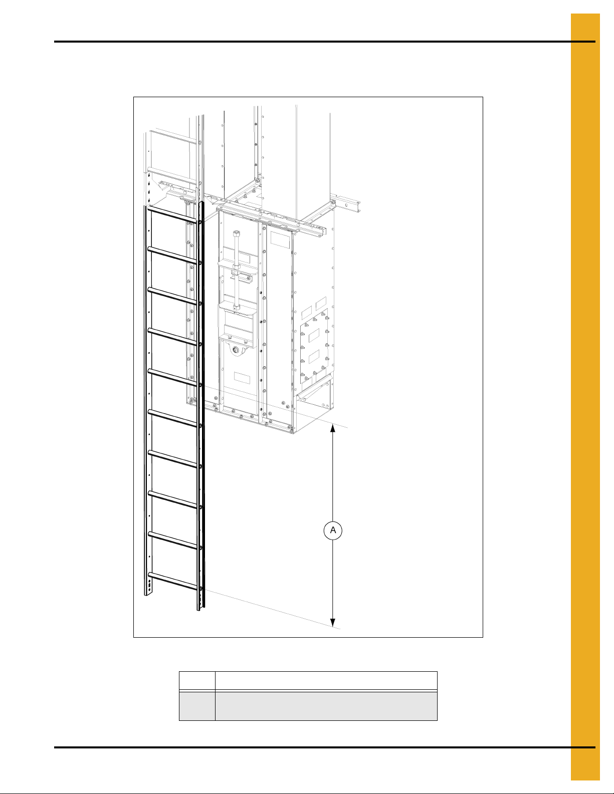
Trim Ladder to Ground
Install Boot Ladder Section
1. Trim a 10' ladder section to sit so that the first ladder rung is 12" from the ground. (See Figure 6G.)
PNEG-1807CE CE Compliant 16"-24" Bucket Elevator Platform and Ladder “X” Series 23
Figure 6G
Ref # Description
Cut this section of the ladder so bottom rung of the
A
ladder is 12" from the ground.
Page 24
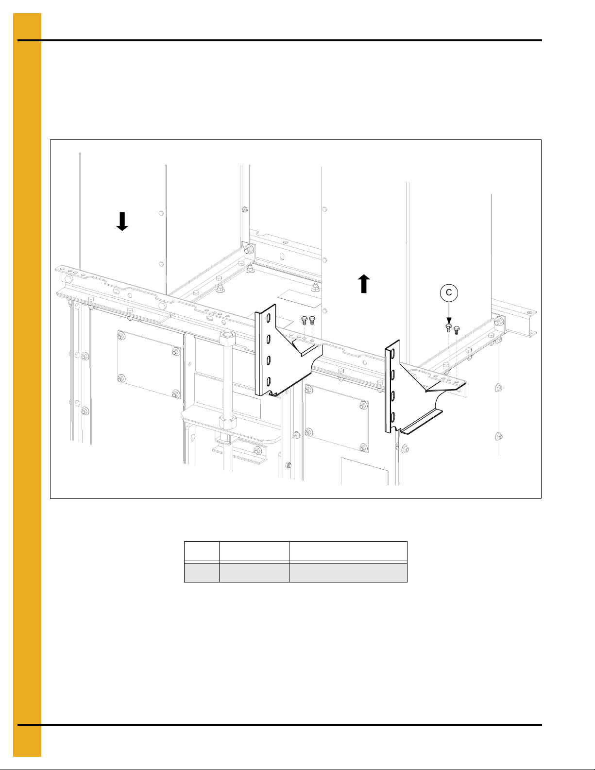
6. Tie Angles, Ladder Brackets and Safety Cages
Ladder to Ladder Brackets
Install Boot Ladder Section (Continued)
2. Attach trimmed ladder section to the left and right ladder brackets using 1/2" x 1" hex bolts through
the bottom most set of holes.
3. Attach the next ladder section to the ladder brackets using 1/2" x 1" hex bolts through the top set of
holes. (See Figure 6H.)
Figure 6H
Ref # Part # Description
B LAD1648TLH Trunk Support Bracket L.H. Side
C LAD1648TRH Trunk Support Bracket R.H. Side
D S-7935 1/2" x 1" Hex Bolt
4. Secure the bottom of the ladder to the boot or ground. NOTE: Bracket for this step is not included.
24 PNEG-1807CE CE Compliant 16"-24" Bucket Elevator Platform and Ladder “X” Series
Page 25
6. Tie Angles, Ladder Brackets and Safety Cages
Tie Angle Installation Locations
Down-leg side
Ladder Side
Ladder side
Up-leg side
Non-ladder side
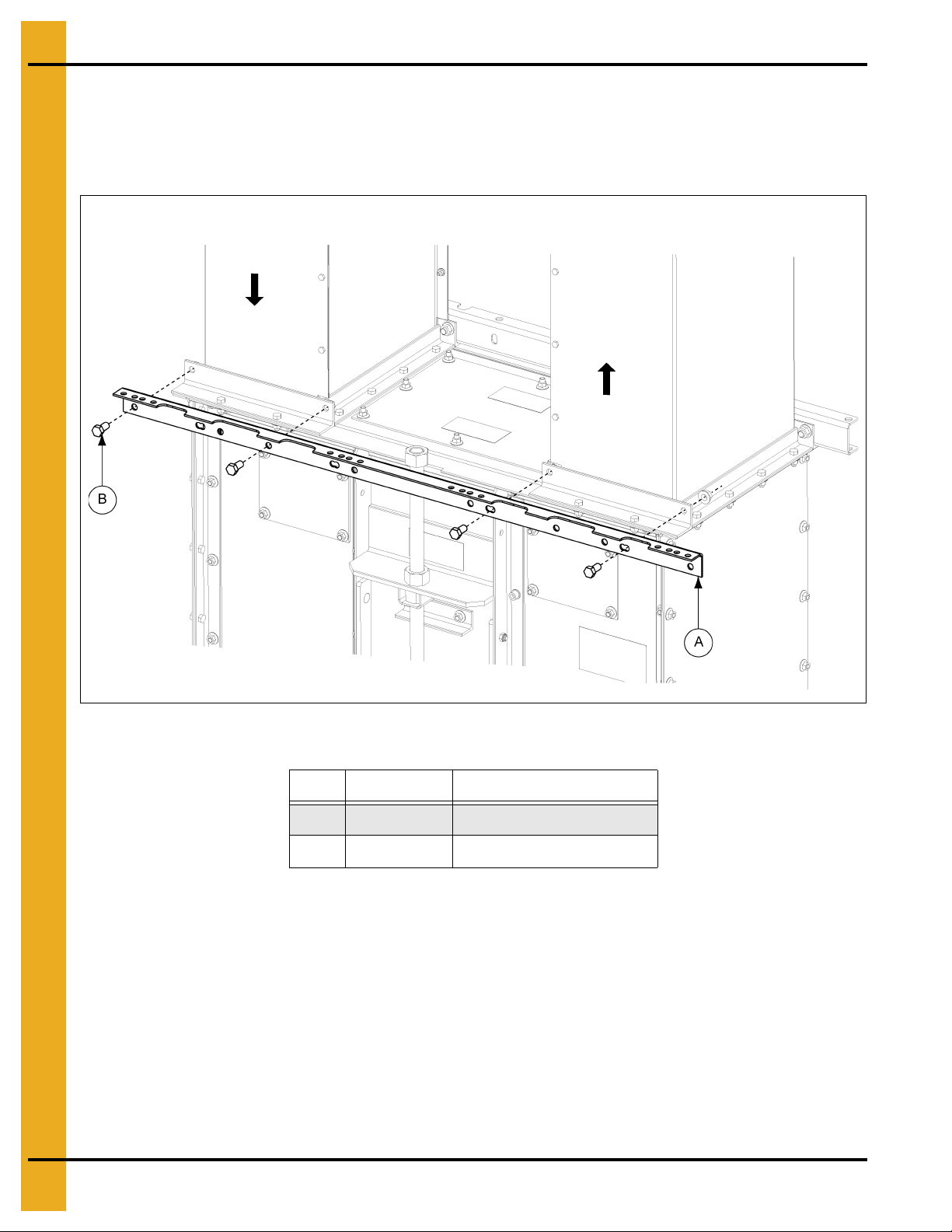
Tie Angles to Trunking
1. On the LADDER SIDE, use 1/2" x 1" bolts. See Figures 6I-6K on Pages 25-27 for the correct location
of bolts for each elevator size.
Tie angle must be installed at every trunking seam. NOTE: The bottom tie angle will be replaced
with a rest platform tie angle (GECT1640FCRPX2) where a rest platform is to be installed.
(See Figure 6I.)
Ref # Part # Description
A BECT1640FX
A GECT1640FX
B S-7935 1/2" x 1" Hex Bolt
PNEG-1807CE CE Compliant 16"-24" Bucket Elevator Platform and Ladder “X” Series 25
Figure 6I Tie Angle Installation Locations
16"-24" Type “X” Trunking Tie Angle
Page 26
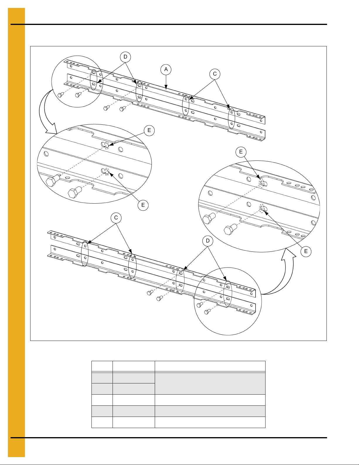
6. Tie Angles, Ladder Brackets and Safety Cages
Ladder side
Non-ladder side
16" Bolt Locations
Tie Angles to Trunking (Continued)
Figure 6J 16" Bucket Elevator Tie Angles to Trunking Bolt Locations
Ref # Part # Description
A BECT1640FX
A GECT1640FX
C Up-Leg Set
D Down-Leg Set
E Install Bolt Here
26 PNEG-1807CE CE Compliant 16"-24" Bucket Elevator Platform and Ladder “X” Series
16"-24" Type “X” Trunking Tie Angle
Page 27
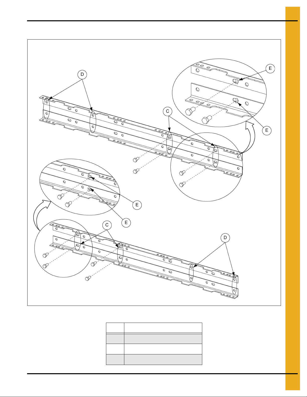
6. Tie Angles, Ladder Brackets and Safety Cages
24" Bolt Locations
Ladder side
Non-ladder side
Tie Angles to Trunking (Continued)
PNEG-1807CE CE Compliant 16"-24" Bucket Elevator Platform and Ladder “X” Series 27
Figure 6K 24" Bucket Elevator Tie Angles to Trunking Bolt Locations
Ref # Description
C Up-Leg Set
D Down-Leg Set
E Install Bolt Here
Page 28

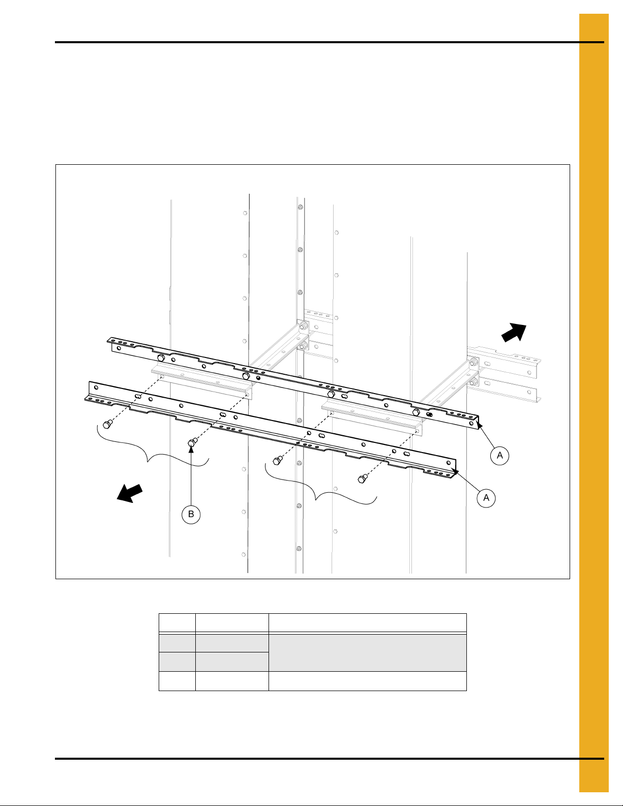
6. Tie Angles, Ladder Brackets and Safety Cages
Ladder Support
Brackets Parts
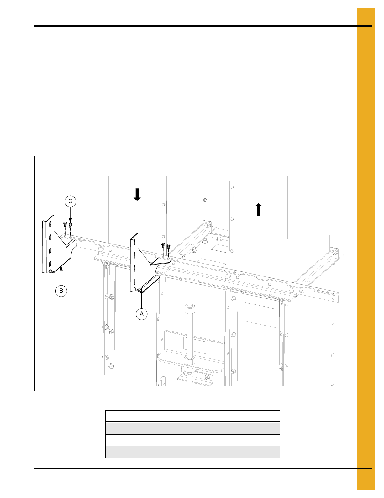
Ladder Support Brackets
1. Attach ladder support brackets to tie angle using 3/8" x 1" hex bolts (S-7469). Use th e holes shown
in Figures 6L-6P on Pages 28-30 for each size elevator.
2. Mount the upper right and upper left hand ladder support brackets to the top tie angle wit h 3/8" bolts.
3. Mount the lower right hand and lower left hand ladder support brackets to the bottom tie angle with
3/8" bolts.
4. Secure the flanges of the ladder brackets together with 3/8" x 1" hex bolts.
NOTE: You will only use one set of ladder brackets, either the up-leg set or the down-leg set.
Figure 6L Ladder Support Bracket Parts
Ref # Part # Description
A LAD1648TLH1 Bottom Trunk Support Bracket L.H. Side
B LAD1648TLH2 Top Trunk Support Bracket L.H. Side
C LAD1648TRH1 Bottom Trunk Support Bracket R.H. Side
D LAD1648TRH2 Top Trunk Support Bracket R.H. Side
E Tie Angles
28 PNEG-1807CE CE Compliant 16"-24" Bucket Elevator Platform and Ladder “X” Series
Page 29

6. Tie Angles, Ladder Brackets and Safety Cages
16" Ladder Brackets on Up-Leg
16" Ladder Brackets on Down-Leg
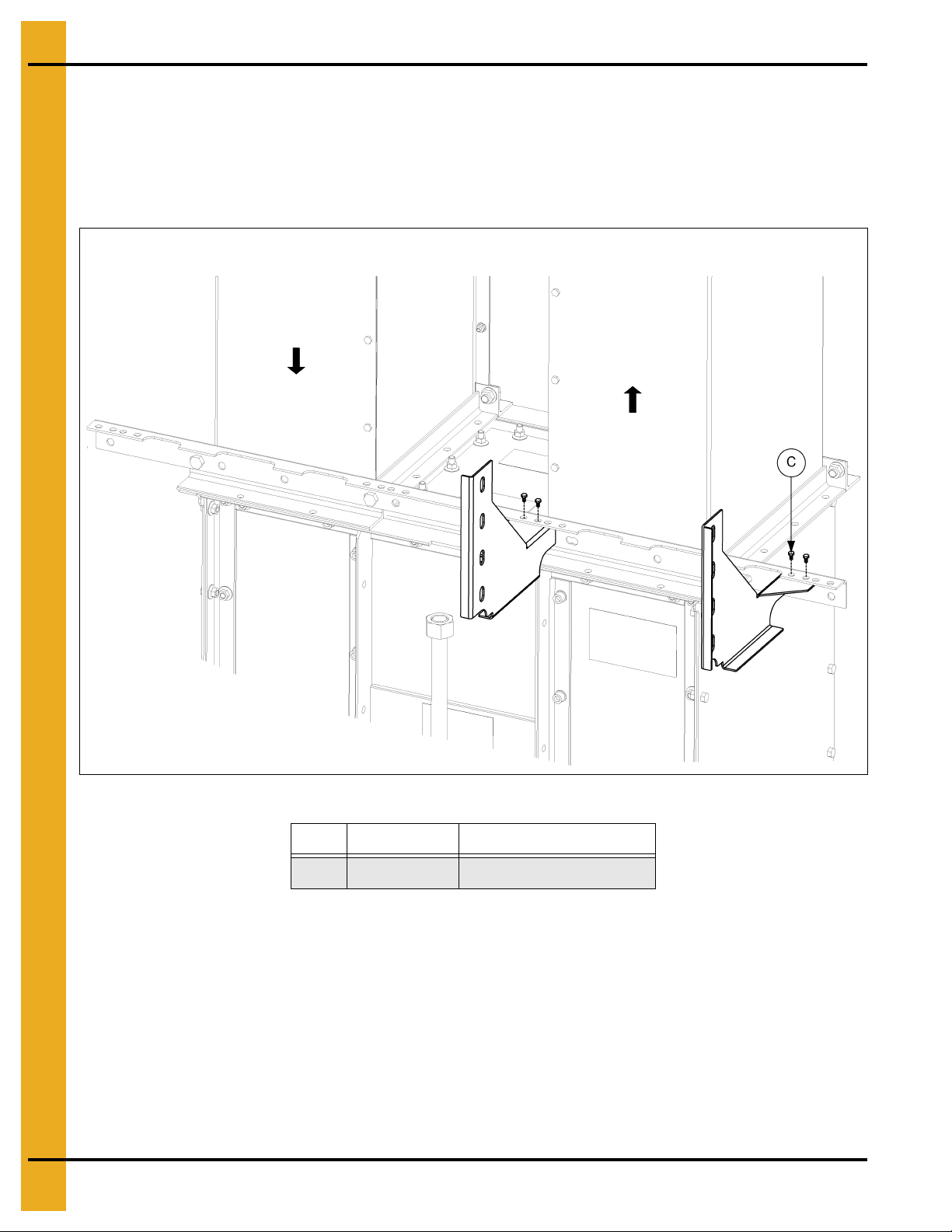
Ladder Support Brackets (Continued)
Figure 6M 16" Ladder Bracket Location for Up-Leg
Figure 6N 16" Ladder Bracket Location for Down-Leg
Ref # Part # Description
F BECT1640FX
F GECT1640FX
G S-7469 3/8" x 1" Bolt
H S-968 3/8" Flange Nut
PNEG-1807CE CE Compliant 16"-24" Bucket Elevator Platform and Ladder “X” Series 29
16" Type “X” Trunking Tie Angle
Page 30

6. Tie Angles, Ladder Brackets and Safety Cages
24" Ladder Brackets on Up-Leg
24" Ladder Brackets on Down-Leg
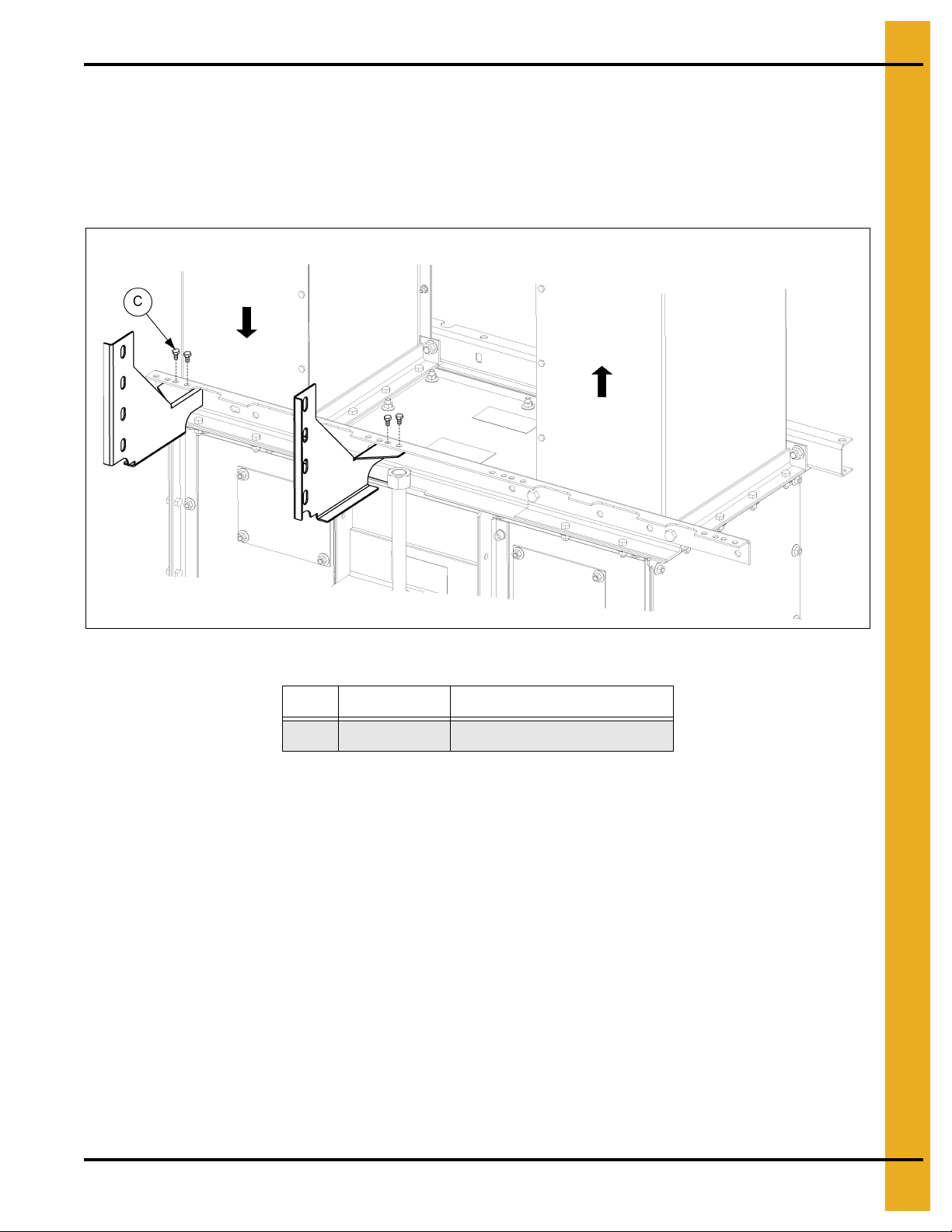
Ladder Support Brackets (Continued)
Figure 6O 24" Ladder Bracket Location for Up-Leg
Figure 6P 24" Ladder Bracket Location for Down-Leg
Ref # Part # Description
F BECT1640FX
F GECT1640FX
G S-7469 3/8" x 1" Bolt
H S-968 3/8" Flange Nut
30 PNEG-1807CE CE Compliant 16"-24" Bucket Elevator Platform and Ladder “X” Series
24" Type “X” Trunking Tie Angle
Page 31

6. Tie Angles, Ladder Brackets and Safety Cages
Attach Ladders to Ladder Brackets
1. Attach ladder sections to the ladder brackets using 1/2" x 1" hex bolts (S-7935). (See Figure 6Q.)
Figure 6Q
Ref # Part # Description
A LAD1648TLH1 Bottom Trunk Support Bracket L.H. Side
B LAD1648TLH2 Top Trunk Support Bracket L.H. Side
C LAD1648TRH1 Bottom Trunk Support Bracket R.H. Side
D LAD1648TRH2 Top Trunk Support Bracket R.H. Side
10FOOTRFX or
E
10FOOTX
F S-7935 1/2" x 1" Hex Bolt
G Ladder Section
10' Ladder Section
PNEG-1807CE CE Compliant 16"-24" Bucket Elevator Platform and Ladder “X” Series 31
Page 32

6. Tie Angles, Ladder Brackets and Safety Cages
Safety Cage Installation
Safety cage entrance must be installed to the ladders within 7'-8' from the ground or platform deck.
(See Figure 6R.)
Figure 6R
Ref # Description
A Safety Cage
32 PNEG-1807CE CE Compliant 16"-24" Bucket Elevator Platform and Ladder “X” Series
Page 33

6. Tie Angles, Ladder Brackets and Safety Cages
Install Safety Cage
Safety cages are 10' sections, with the exception of the 3' entrance section.
1. Locate safety cage hoops (LDR-BCKTBHP) along the ladder rails where the safety cage hoops will
be installed. NOTE: The end hoops of a 10' section are spaced 4' from the two (2) middle hoops,
which are spaced 2' apart. See Figure 6S for spacing. (See Figure 6S.)
Figure 6S 10' Safety Cage Section
Ref # Part # Description
A LDR-10FTCAGE 10' Safety Cage Strap
B LDR-3FTCAGE 3' Safety Cage Strap
C 3' Safety Cage Entrance Section
PNEG-1807CE CE Compliant 16"-24" Bucket Elevator Platform and Ladder “X” Series 33
Page 34

6. Tie Angles, Ladder Brackets and Safety Cages
Install Safety Cage (Continued)
2. Attach safety cage hoops to ladder using 1/2" x 1" bolts and nuts. (See Figure 6T.)
Figure 6T
Ref # Part # Description
D S-7935 1/2" x 1" HHCS Bolt
E S-8506 1/2" Flange Nut
10FOOTRFWX or
F
10FOOTX
G Safety Cage Hoop
34 PNEG-1807CE CE Compliant 16"-24" Bucket Elevator Platform and Ladder “X” Series
10' Ladder Section
Page 35

6. Tie Angles, Ladder Brackets and Safety Cages
Vertical Straps
Install Safety Cage (Continued)
3. Install the seven (7) 10' safety cage straps along the safety cage hoops using 5/16" x 3/4" bolts and
nuts. NOTE: Bolt heads should be to the inside of the hoop. (See Figure 6U.)
PNEG-1807CE CE Compliant 16"-24" Bucket Elevator Platform and Ladder “X” Series 35
Figure 6U
Ref # Part # Description
A LDR-10FTCAGE 10' Safety Cage Strap
B LDR-3FTCAGE 3' Safety Cage Strap
H LDR-BCKTBHP Safety Cage Hoop Entrance
I S-7645 5/16" x 3/4" Bolt
J S-10268 5/16" Flange Nut
K LDR-BCKTHOOP Safety Cage Hoop Standard
L Bottom Holes
M Top Holes
N Leave these hole open for vertical bars.
Page 36

7. Rest Platform
Tie Angle Etched Identification Holes
16" Tie Angle Bolt
Locations - Ladder Side
Down-leg
Up-leg
Chapter 7: Rest Platform
Rest Platform Tie Angles to Bucket Elevators
1. Install rest platform tie angles to the lower trunking on both the ladder side and non-ladder side of the
trunking. Use 1/2" x 1" bolts through the bolt holes indicated for the bucket elevator size being
installed. (See Figure 7A.)
NOTE: Bolt hole starting location on left side of tie angle is marked with the bucket size.
Figure 7A Tie Angle with Etched Numbers
Figure 7B 16" Rest Platform Tie Angle Bolt Locations - Ladder Side
Ref # Part # Description Ref # Part # Description
A GECT1640FCRPX2 16"-24" Rest Platform Tie Angle C S-8506 1/2" Flange Nut
B S-7935 1/2" x 1" Bolt
36 PNEG-1807CE CE Compliant 16"-24" Bucket Elevator Platform and Ladder “X” Series
D Hole Marked 24" 16". Use Side Marked 16".
Page 37

7. Rest Platform
24" Tie Angle Bolt Locations - Ladder Side
Down-leg
Up-leg
Rest Platform Tie Angles to Bucket Elevators (Continued)
Figure 7C 24" Rest Platform Tie Angle Bolt Locations - Ladder Side
Ref # Part # Description
A GECT1640FCRPX2 16"-24" Rest Platform Tie Angle
B S-7935 1/2" x 1" Bolt
C S-8506 1/2" Flange Nut
E Hole Marked 24" 16". Use Side Marked 24".
PNEG-1807CE CE Compliant 16"-24" Bucket Elevator Platform and Ladder “X” Series 37
Page 38

7. Rest Platform
16" Tie Angle Bolt Locations - Non-Ladder Side
Down-leg
Up-leg
Rest Platform Tie Angles to Bucket Elevators (Continued)
Figure 7D 16" Rest Platform Tie Angle Bolt Locations - Non-Ladder Side
Ref # Part # Description
A GECT1640FCRPX2 16"-24" Rest Platform Tie Angle
B S-7935 1/2" x 1" Bolt
C S-8506 1/2" Flange Nut
D Hole Marked 24" 16". Use Side Marked 16".
38 PNEG-1807CE CE Compliant 16"-24" Bucket Elevator Platform and Ladder “X” Series
Page 39

7. Rest Platform
24" Tie Angle Bolt Locations - Non-Ladder Side
Down-leg
Up-leg
Rest Platform Tie Angles to Bucket Elevators (Continued)
Figure 7E 24" Rest Platform Tie Angle Bolt Locations - Non-Ladder Side
Ref # Part # Description
A GECT1640FCRPX2 16"-24" Rest Platform Tie Angle
B S-7935 1/2" x 1" Bolt
C S-8506 1/2" Flange Nut
E Hole Marked 24" 16". Use Side Marked 24".
PNEG-1807CE CE Compliant 16"-24" Bucket Elevator Platform and Ladder “X” Series 39
Page 40

7. Rest Platform
16"-24" Tie Angle Bolt Locations - Mounting Channels
Down-leg
Up-leg
Attach Rest Platform Channel to the Rest Platform Tie Angle
1. Connect rest platform mounting channels to the rest platform tie angles using 1/2" x 1" bolts.
Bolt hole locations for 16"-24" bucket elevator will be the same. (See Figure 7F.)
Figure 7F Bolt hole locations for 16"-24" rest platform mounting channels to tie angles.
Ref # Part # Description
A GECT1640FCRPX2 16"-24" Rest Platform Tie Angle
B S-7935 1/2" x 1" Bolt
C S-8506 1/2" Flange Nut
D RP1636MCX 16"-36" Rest Platform Mounting Channel
40 PNEG-1807CE CE Compliant 16"-24" Bucket Elevator Platform and Ladder “X” Series
Page 41

7. Rest Platform
Rest Platform Channels
Rest Platform Cross Channel to Rest Platform Mounting Channels
1. Place the rest platform cross channels between the rest platform mounting channels and connect
those using 3/8" x 3/4" hex bolts. (See Figure 7G.)
Figure 7G Rest Platform Cross Channel to Rest Platform Mounting Channels
Ref # Part # Description
A RP1636CCX Rest Platform Cross Channel
B RP1636MCX Rest Platform Mounting Channel
C S-7105 3/8" x 3/4" Hex Bolt
D S-968 3/8" Flange Nut
PNEG-1807CE CE Compliant 16"-24" Bucket Elevator Platform and Ladder “X” Series 41
Page 42

7. Rest Platform
Rest Platform Deck Plate
Rest Platform Cross Channel to Rest Platform Mounting
Channels (Continued)
2. Attach rest platform deck to the bottom of the rest platform mounting channels and rest platform
cross channels, using 3/8" x 3/4" hex bolts. Bolt heads should be installed against the deck plate.
(See Figure 7H.) NOTE: The deck plate can be mounted on either the right or left side, but the flange
must be mounted towards the opening.
Figure 7H Deck Plate
Ref # Part # Description
A RP1636CCX Rest Platform Cross Channel
B RP1636MCX Rest Platform Mounti ng Channel
C S-7105 3/8" x 3/4" Hex Bolt
D S-968 3/8" Flange Nut
E RP1636FDP Rest Platform Flat Deck Plate
F Deck Flange Towards Opening
42 PNEG-1807CE CE Compliant 16"-24" Bucket Elevator Platform and Ladder “X” Series
Page 43

7. Rest Platform
Rest Platform Handrail Posts
Rest Platform Cross Channel to Rest Platform Mounting
Channels (Continued)
3. Install the handrail platform posts to the rest platform mounting channels and rest platform channels
using six (6) 5/16" x 3/4" flanged hex bolts for each post, four (4) bolt to the front and two (2) on the
side. (See Figure 7I.)
PNEG-1807CE CE Compliant 16"-24" Bucket Elevator Platform and Ladder “X” Series 43
Figure 7I
Ref # Part # Description
G HP1648HCP Handrail Platform Posts
H S-6606 5/16" x 3/4" Flange Bolt
I S-10268 5/16" Flange Nut
Page 44

7. Rest Platform
18"
Final length
Cut 18"
Cut 18"
Intermediate Handrails
18"
Final length
Rest Platform Cross Channel to Rest Platform Mounting
Channels (Continued)
4. Assemble the intermediate handrails by sliding the small handrail into the larger handrail to create a
telescoping handrail that can be adjusted to the correct length between the posts. Two (2) of the
small intermediate handrails and two (2) of the large intermediate handrails will need to be cut to fit.
The starting length of each rail is 36". Cut 18" off the end of each rail so the final length of each rail
is 18". (See Figure 7J.)
Figure 7J
Ref # Description
J Cut Two (2) Small Intermediate Rails
K Cut Two (2) Large Intermediate Rails
44 PNEG-1807CE CE Compliant 16"-24" Bucket Elevator Platform and Ladder “X” Series
Page 45

7. Rest Platform
Telescoping Intermediate Handrail Posts
Rest Platform Cross Channel to Rest Platform Mounting
Channels (Continued)
5. Install the front and back intermediate handrails to the platform posts using 5/16" x 3/4" flanged hex
bolts. Adjust the rail into position by sliding it out to the correct length.
6. After cutting the two (2) large and two (2) small intermediate handrails, slide them to the correct
length and install them to the handrail posts on the short sides of the platform using 5/16" x 3/4"
flanged hex bolts. (See Figure 7K.)
Ref # Part # Description
H S-6606 5/16" x 3/4" Flange Bolt
I S-10268 5/16" Flange Nut
L LDR-4087 Large Intermediate Handrail
M LDR-4088 Small Intermediate Handrail
N Slide Smaller Rail into Larger Rail
PNEG-1807CE CE Compliant 16"-24" Bucket Elevator Platform and Ladder “X” Series 45
Figure 7K
Page 46

7. Rest Platform
Handrails
Rest Platform Cross Channel to Rest Platform Mounting
Channels (Continued)
7. Connect the front rest platform handrails and the side rest platform handrails to the handrail platform
post using 5/16" x 2" hex bolts. (See Figure 7L.)
Figure 7L
Ref # Part # Description
I S-10268 5/16" Flange Nut
O RP1648HF 57-1/2" Handrail
P RP1648HS 30.1" Handrail
Q S-7877 5/16" x 2" Flange Bolt
46 PNEG-1807CE CE Compliant 16"-24" Bucket Elevator Platform and Ladder “X” Series
Page 47

7. Rest Platform
Platform Braces
Rest Platform Cross Channel to Rest Platform Mounting
Channels (Continued)
8. Platform braces must be installed from handrail posts to mounting and cross channels using
5/16" x 3/4" flanged hex bolts. Braces should be attached to the outside of the platform post and to
the inside of the mounting and cross channels. NOTE: Safety cage bars (LDR-517BE) are used
as platform braces/tie angle braces through out this installation. Bolt heads should be on inside of
platforms. (See Figure 7M.)
PNEG-1807CE CE Compliant 16"-24" Bucket Elevator Platform and Ladder “X” Series 47
Figure 7M
Ref # Part # Description
A RP1636CCX Rest Platform Cross Channel
B RP1636MCX Rest Platform Mounting Channel
H S-6606 5/16" x 3/4" Flange Bolt
I S-10268 5/16" Flange Nut
R LDR-5171BE Brace
Page 48

7. Rest Platform
Rest Platform Cross Channel to Rest Platform Mounting
Channels (Continued)
9. Install ladder support brackets to the rest platform cross channel using 3/8" x 3/4" hex bolts.
10. Attach ladders to ladder support brackets using 1/2" x 3/4" hex bolts. (See Figure 7N.)
Figure 7N
Ref # Part # Description
A RP1636CCX Rest Platform Cross Channel
C S-7105 3/8" x 3/4" Hex Bolt
S LAD1648BLH Ladder Support L.H. Bracket
T LAD1648BRH Ladder Support R.H. Bracket
U S-7932 1/2" x 3/4" Hex Bolt
48 PNEG-1807CE CE Compliant 16"-24" Bucket Elevator Platform and Ladder “X” Series
Page 49

Ladder Support
NOTE: Drill holes where necessary.
7. Rest Platform
PNEG-1807CE CE Compliant 16"-24" Bucket Elevator Platform and Ladder “X” Series 49
Figure 7O
Ref # Part # Description
14FOOTRFWX or
A
14FOOTX
B RP1648LS Ladder Support Rest Platform
C RP1648HSX 48" HSP Sides 43.605" Outside Handrail
D S-10136 U-Bolt 1/4"-20 x 1-1/2"
14' Ladder Section
Page 50

8. 16"-24" Head Platform Assembly
16"-24" Cross Deck Support
Channels to Head
Chapter 8: 16"-24" Head Platform Assembly
Considerable time is dedicated at the beginning of this manual to the proper orientation of channels and
decks. This is because the orientation of these elements is essential to the proper construction of the
head platform.
1. There are many ways to get the orientation wrong and only one way to get it right.
2. Proper orientation of the channels and decks is essential proper assembly.
3. Proper construction of the head platform can only be completed if the initial orientation of the
channels is done correctly.
Please take time to confirm that the orientation of these early elements is correct before you begin to
assemble the decking on to the channels.
Attach Main Support Channels to Lower Head
1. Place lower head section on solid and level surface.
2. At both the Discharge End and Up-Leg End, orient the channels so that lip/channel openings face
outward, away from the lower head.
3. Attach each Main Support Channel to the Lower Head Bracket at the top most set o f holes using
3/8" x 1" bolts and nuts and torque to standard specifications. (See Figure 8A.)
Figure 8A Cross Deck Support Channels Head
Ref # Part # Description
A S-7469 3/8" x 1" Bolt
B S-10028 3/8" Flange Nut
C HSP16001X 16"-24" Main Support Channel
50 PNEG-1807CE CE Compliant 16"-24" Bucket Elevator Platform and Ladder “X” Series
Page 51

8. 16"-24" Head Platform Assembly
A1
on Toe board
16"-24" Deck A Toe Board to Channel Mounting
A2
on Toe board
A3
on Toe board
DECK A
Install Deck A and Toe Board
1. Orient the lip of the side toe board (HP1624STBX) out/away from the lower head and slide into place
on non-drive side. Toe board hole A1 should be at the discharge end and A3 is at the up-leg end.
2. Locate pre-assembled Deck A, which consists of the hatch opening and connecting flanges.
3. Using a punch as needed for alignment, connect Deck A to the side toe board with 3/8" flange nuts
(S-10028) and 3/8" x 3/4" flange bolts (S-7105). Torque to standard specifications. (See Figure 8 B.)
a. Deck hole A1 to toe board hole A1.
b. Deck hole A2 to toe board hole A2.
c. Deck hole A3 to toe board hole A3.
NOTE: Due to snug fit, slide side toe board in place before securing Deck A or any subsequent decking.
Figure 8B Deck A Toe Board Channel Location
Ref # Description
NOTE: 24" Position shown. Only difference between
A
16" and 24" is location of discharge channel.
PNEG-1807CE CE Compliant 16"-24" Bucket Elevator Platform and Ladder “X” Series 51
Page 52

8. 16"-24" Head Platform Assembly
16"-24" Deck A to Support Channels
DECK A
Install Deck A to Main Support Channels
1. Using 3/8" x 1" carriage bolts (S-3585) and 3/8" flange nuts (S-10028), connect Deck A to main
support channel. IMPORTANT: Connect every hole. (See Figure 8C.)
Figure 8C Deck A to Support Channels
Ref # Part # Description
A S-3585 3/8" x 1" Carriage Bolt
B S-10028 3/8" Flange Nut
C HSP16001X Main Support Channel
D
52 PNEG-1807CE CE Compliant 16"-24" Bucket Elevator Platform and Ladder “X” Series
NOTE: 16" will use this row of holes.
Page 53

8. 16"-24" Head Platform Assembly
NOTE: 24" Shown. 16" Assemble the same.
16"-24" Deck A HP Deck Supports
DECK A
Install Deck A to Main Support Channels (Continued)
2. Install decking support (HP1624DS) to up-leg end of Deck A as shown, using 3/8" x 1" bolts (S-7105)
and 3/8" nuts (S-10028).
3. Install the hatch deck support bar (HP1624HDSX) to Deck A. This piece installs on the underside of
Deck A and extends the width of the deck from edge to edge.
Using 3/8" flange nuts (S-10028) and 3/8" x 3/4" flange bolts (S-7105), connect the hatch deck
support bar to Deck A kick plate and through the holes labeled A2 on Deck A and side toe board.
Torque to standard specifications. (See Figure 8D.)
PNEG-1807CE CE Compliant 16"-24" Bucket Elevator Platform and Ladder “X” Series 53
Figure 8D Deck A HP Deck Supports
Ref # Part # Description
E HP1624HDSX Hatch Deck Support Bar
F HP1624DS Decking Support
Page 54

8. 16"-24" Head Platform Assembly
16"-24" Deck C Toe Board
A1
on Toe board
A4
on Toe board
A3
on Toe board
DECK C
Install Deck C and Toe Board
1. Locate pre-assembled Deck C, consisting of two (2) planks and connecting tabs.
2. Slide side toe board into place on the drive side of the lower head.
3. Orient the side toe board so that the hole labeled A1 is at the up-leg end and A3 is at the discharge
end of the lower head.
4. Using a punch as needed for alignment, connect Deck C to side toe board using 3/8" x 1" carriage
bolts (S-3585) with flange nuts (S-10028) and torque to standard specifications. (See Figure 8E.)
a. Deck hole C1 to toe board hole A3.
b. Deck hole C2 to toe board hole A4.
c. Deck hole C3 to toe board hole A1.
NOTE: Due to snug fit, slide side toe board in place before securing Deck C or any subsequent decking.
Figure 8E 24" Deck C Toe Board
Ref # Part # Description
A S-7105 3/8" x 3/4" Flange Bolt
B S-10028 3/8" Flange Nut
C HP1624HDSX Hatch Deck Support Bar
D
54 PNEG-1807CE CE Compliant 16"-24" Bucket Elevator Platform and Ladder “X” Series
NOTE: 24" Position shown. Only difference between
16" and 24" is location of discharge channel location.
Page 55

8. 16"-24" Head Platform Assembly
16"-24" Deck C to
Support Channel
DECK C
16"-24" Deck C HP Deck
Support - Underneath View
Install Deck C to Main Support Channels
1. Using 3/8" x 1" carriage bolts (S-3585) and 3/8" flange nuts (S-10028), connect Deck C to main
support channel. IMPORTANT: Connect every hole. (See Figure 8F.)
2. Install decking support (HP1624DS) to up-leg end of Deck A as shown. Using five (5) 3/8" x 1" bolts
(S-7105) and 3/8" nuts (S-10028).
3. Install the hatch deck support bar (HP1624HDSX) to Deck C. This piece installs on the underside of
Deck C and extends the width of the deck from edge to edge.
a. Using 3/8" flange nuts (S-10028) and 3/8" x 3/4" flange bolts (S-7105), connect the hatch deck
support bar to the kick plate attached to Deck C and to the hole labeled
side toe board and lower head. Torque to standard specifications.
A2
on decking nearest the
(See Figure 8G.)
Figure 8F 16" Deck C to Support Channels
Figure 8G Deck C HP Deck Support as Viewed from Underneath.
Ref # Part # Description Ref # Part # Description
A S-3585 3/8" x 1" Carriage Bolt C HP1624DS HP1624 Decking Support
B S-10028 3/8" Flange Nut
D HP1624HD SX Hatch Deck Support Bar
PNEG-1807CE CE Compliant 16"-24" Bucket Elevator Platform and Ladder “X” Series 55
Page 56

8. 16"-24" Head Platform Assembly
DECK A
DECK C
16"-24" Decks E, A and C - Underneath View
DECK E
Install Deck E
NOTE: The orientation of the flanges on Deck E is important to prope r assembly. Deck E flanges should
be to the outside of Deck A and Deck C.
1. Locate Deck E. It is the smallest deck.
NOTE: Deck E will attach to Deck A, Deck C, both side toe boards and the main support channel.
2. Using a punch as needed for alignment, connect Deck E to the side toe board using 3/8" x 1" carriage
bolts (S-3585) with flange nuts (S-10028). Torque to standard specifications. (See Figure 8H.)
a. Deck E hole E1 to Deck A hole A5.
b. Deck E hole E2 to Deck A hole A4.
c. Deck E hole E3 to Deck C hole C5.
d. Deck E hole E4 to Deck C hole C4.
Figure 8H Deck E, Deck A and Deck C as Viewed from Underneath.
56 PNEG-1807CE CE Compliant 16"-24" Bucket Elevator Platform and Ladder “X” Series
Page 57

8. 16"-24" Head Platform Assembly
DECK A
DECK C
16"-24" Deck E to Support Channels
DECK E
Install Deck E (Continued)
3. Using 3/8" x 1" carriage bolts (S-3585) and 3/8" flange nuts (S-10028), connect Deck E to main
support channel. IMPORTANT: Connect every hole. (See Figure 8I.)
4. Align Deck E so the flanges are to the outside of Deck A and Deck C. Using 3/8" x 1" bolts (S-7105)
and 3/8" flange nuts (S-10028), connect Deck E to toe boards and flanges of Deck A and Deck C.
(See Figure 8J.)
Ref # Part # Description
A S-3585 3/8" x 1" Carriage Bolt
B S-10028 3/8" Flange Nut
C Deck E Flanges Outside Deck A and Deck C
PNEG-1807CE CE Compliant 16"-24" Bucket Elevator Platform and Ladder “X” Series 57
Figure 8I 24" Deck E to Support Channels
Page 58

8. 16"-24" Head Platform Assembly
DECK C
DECK A
Deck E
DECK E
Install Deck E (Continued)
Figure 8J 24" Deck E
Ref # Part # Description
B S-10028 3/8" Flange Nut
D S-7105 3/8" x 1" Bolt
58 PNEG-1807CE CE Compliant 16"-24" Bucket Elevator Platform and Ladder “X” Series
Page 59

8. 16"-24" Head Platform Assembly
16" Deck E
16" Deck E
Install Adapter Bracket for 16" Platforms
NOTE: The adapter bracket attaches to decking and toe boards. The flanges should be to the outside of
Deck A and Deck C.
1. Using three (3) 3/8" x 1" carriage bolts (S-3585) and 3/8" flange nuts (S-10028), install the adapter
bracket to cross deck support channel at the up-leg end of the platform between Deck A and side
toe board and between Deck C and side toe boards. (See Figure 8K.)
2. Attach deck adapter bracket (HP1624AB) to Deck A, Deck C and toe boards using four (4) 3/8" x 1"
bolts (S-7105) and nuts. (See Figure 8L.)
Figure 8K Deck Adapter Bracket to Channel Figure 8L Deck Adapter Bracket to Decks
Ref # Part # Description
A S-3585 3/8" x 1" Carriage Bolt
B HP1624AB 16" HP Adapter Bracket
Ref # Part # Description
B HP1624AB 16" HP Adapter Bracket
C S-7105 3/8" x 1" Bolt
D S-10028 3/8" Flange Nut
PNEG-1807CE CE Compliant 16"-24" Bucket Elevator Platform and Ladder “X” Series 59
Page 60

8. 16"-24" Head Platform Assembly
Hatch Filler Plate
Install Hatch Filler Plate
1. Using 3/8" x 1" carriage bolts (S-3585) and 3/8" flange nuts (S-10028), install the hatch filler plate
(HP1624HDF) over the un-used opening. (See Figure 8M.)
Figure 8M Deck Plate
Ref # Part # Description
A HP1624HDF Hatch Deck Filler Plate
B S-3585 3/8" x 1" Carriage Bolt
C S-10028 3/8" Flange Nut
60 PNEG-1807CE CE Compliant 16"-24" Bucket Elevator Platform and Ladder “X” Series
Page 61

8. 16"-24" Head Platform Assembly
Deck E Rail Support Brackets
Install Rail Supports to Deck E
1. Attach two (2) head platform rail supports (HP1648HSH) to Deck E as shown using 3/8" x 1" bolts
(S-7105) and 3/8" flange nuts (S-10028). (See Figure 8N.)
PNEG-1807CE CE Compliant 16"-24" Bucket Elevator Platform and Ladder “X” Series 61
Figure 8N 24" Deck E Rail Support Brackets
Ref # Part # Description
A HP1648HSH Head Platform Rail Support
B S-7105 3/8" x 1" Bolt
C S-10028 3/8" Flange Nut
Page 62

8. 16"-24" Head Platform Assembly
“W” Corner Posts
Install “W” Posts (“Corner Posts” x 4)
1. At each corner, align bottom edges of “W” corner posts (HP1648HWP) with bottom edge of
platform decking.
2. Attach each “W” corner post to decking using 5/16" x 3/4" flange bolts (S-6606) and 5/16" flange nuts
(S-10268). Torque to standard specifications. (See Figure 8O.)
Figure 8O
Ref # Part # Description
A HP1648HWP Head/Distributor “W” Corner Post
B S-6606 5/16" x 3/4" Flange Bolt
C S-10268 5/16" Flange Nut
62 PNEG-1807CE CE Compliant 16"-24" Bucket Elevator Platform and Ladder “X” Series
Page 63

8. 16"-24" Head Platform Assembly
Middle End Posts
Install Platform Posts
NOTE: Platform posts are not flush with bottom of deck.
1. At the up-leg end, align two (2) platform posts (HP1648HCP) as described and connect to the
decking where Deck E intersects with Decks A and C. Use 5/16" hex flange nuts (S-10268) and
5/16" x 3/4" flange bolts, connect the platform posts to the decking.
NOTE: Rail support braces should be between the posts.
2. At the discharge end, align platform posts as described and attach one platform posts (HP1648HCP)
to the edge of Deck C and Deck A nearest the lower head. (See Figure 8P.)
PNEG-1807CE CE Compliant 16"-24" Bucket Elevator Platform and Ladder “X” Series 63
Figure 8P Middle End Posts
Ref # Part # Description
A HP1648HCP Platform Post
B S-6606 5/16" x 3/4" Flange Bolt
C S-10268 5/16" Flang e Nut
Page 64

8. 16"-24" Head Platform Assembly
Platform Post
Install Platform Posts (Continued)
3. At the middle of Deck A and Deck C, install platform post (HP1648HCP) as shown and connect
to the decking through a rail support (HP1648HSH). Use 5/16" hex flange nuts (S-10268) and
5/16" x 3/4" flange bolts to connect the rail supports and platform posts to the decking.
(See Figure 8Q.)
Figure 8Q Deck A Post Bracket
Ref # Part # Description
A HP1648HCP Platform Post
D HP1648HSH Head Platform Handrail Support
64 PNEG-1807CE CE Compliant 16"-24" Bucket Elevator Platform and Ladder “X” Series
Page 65

8. 16"-24" Head Platform Assembly
Intermediate Handrails
Install Intermediate Handrails
IMPORTANT: Trim each rail as listed. Do NOT attempt to make entire adjustment by trimming only one
rail. Each rail must be trimmed and installed as stated for proper fit.
IMPORTANT: For safety purp oses, make sure head of bolt is to the inside of platform with nuts on o utside
at all connections.
1. Identify and separate the large and small intermediate handrails.
NOTE: The small intermediate handrail (LDR-4088) fits inside of the large intermediate handrail.
It is critical that large and small rails be properly identified in advance. Rails are cut to
size and cutting the wrong rail or to the wrong length will prevent proper installation.
(See Figure 8R.)
PNEG-1807CE CE Compliant 16"-24" Bucket Elevator Platform and Ladder “X” Series 65
Figure 8R Intermediate Handrails
Ref # Part # Description
A LDR-4088 Sma ll Intermediate Handrail
B S-6606 5/16" x 3/4" Flange Bolt
C S-10268 5/16" Hex Flange Nut
D LDR-4087 Large Intermediate Handrail
E
F
G
H
Hatch side large intermediate handrail needs to be at
location of latch.
Cut 4" off of each intermediate large and small rail so
the remaining length for each is 32".
Cut 15" off of each intermediate large and small rail so
the remaining length for each is 21".
Cut 4" off of each intermediate large and small rail so
the remaining length for each is 32".
Page 66

8. 16"-24" Head Platform Assembly
Cut 15"
Cut 15"
36"
Large Intermediate Rail
36"
Small Intermediate Rail
Telescoping Handrails
Cut 4"
Cut 4"
36"
Large Intermediate Rail
36"
Small Intermediate Rail
Telescoping Handrails
Install Intermediate Handrails (Continued)
2. Trim two (2) large and two (2) small rails by 15" each so that the remaining length of each rail, both
small and large, is 21". (See Figure 8S.)
a. Install these rails across the Deck A, Deck C, Deck E side of the platform and the opposite side
as shown.
b. Insert one small rail inside of one large rail and telescope the joined rails from the “W” corner post
to the platform post as shown in Figure 8R on Page 65.
c. Attach to “W” posts (corner posts) and platform posts using nuts (S-10268) and bolts (S-6066).
d. Torque to standard specifications.
Figure 8S 21" Telescoping Handrail
3. Trim two (2) large and two (2) small rails by 4" each so remaining length of each rail, both small and
large, is 32". (See Figure 8T.)
a. Install these rails across the up-leg and down-leg sides of the platform as shown.
b. Insert one small rail inside of one large rail telescope the joined rails from the “W” corner posts
to platform posts as shown in Figure 8R on Page 65.
c. Attach to “W” posts (corner posts) and platform posts using nuts (S-10268) and bolts (S-6066).
d. Torque to standard specifications.
Figure 8T 32" Telescoping Handrail
66 PNEG-1807CE CE Compliant 16"-24" Bucket Elevator Platform and Ladder “X” Series
Page 67

8. 16"-24" Head Platform Assembly
Top Rails
Install Upper Handrails
IMPORTANT: For safety purposes, make sure head of bolts is to the inside of platform with nuts on
outside at all connections.
NOTE: Upper handrails do not require any cutting prior to installation.
1. Attach two (2) 25.6" in length middle drive handrails (HP1624HMD) along Deck E and the lower head.
These are the two (2) shortest sections of upper handrail. Connect using 5/16" nuts (S-10268) and
5/16" x 2" bolts (S-7877). Torque to standard specifications. (See Figure 8U.)
2. Attach four (4) hatch handrails (HP1648HHS): one on each side of the middle drive at each end of
the platform. Handrails will fit without adjustment. Connect using 5/16" nut (S-10268) and 5/16" x 2"
bolts (S-7877). Torque to standard specifications.
3. Two (2) 59.183" far hatch handrails (HP1624HFH) and two (2) 54.65" handrails (HP1624HNH) opposite
each other along Deck A and Deck C using 5/16" x 2" bolts (S-7877) and 5/16" nuts (S-10268).
Figure 8U Top Rails
Ref # Part # Description
A HP1624HFH 59.183" Far Hatch Handrail
B HP1648HLH 36.895" Hatch Handrail
C HP1648HMD 26.7" Middle Drive Handrail
D HP1624HNH 54.65" Near Hatch
E S-7877 5/16" x 2" Bolt
F S-10268 5/16" Flange Nut
PNEG-1807CE CE Compliant 16"-24" Bucket Elevator Platform and Ladder “X” Series 67
Page 68

8. 16"-24" Head Platform Assembly
Tie Braces
(Safety Cage Bars)
Install Tie Braces (Safety Cage Bars)
NOTE: Safety cage bars (LDR-5171BE) are used as tie braces in this installation.
IMPORTANT: For safety purposes, make sure head of bolts are to the inside of platform with nuts on
outside at all connections.
1. At each of the four (4) “W” corner posts (HP1648HWP), attach two (2) tie braces (safety cage bar
LDR-5171BE) from the lower half of the post to the deck kick plate using 5/16" nuts (S-10268) and
5/16" x 3/4" flange bolts (S-6606). (See Figure 8V.)
NOTE: Tie braces may be oriented on the inside or outside of the decking kick plates based upon
installer preference.
Figure 8V Safety Cage Cross Brace
Ref # Part # Description
A LDR-5171BE 24" Safety Cage Bar
B S-6606 5/16" x 3/4" Flange Bolt
C S-10268 5/16" Hex Flange Nut
NOTE: See Page 69 for hatch door installation.
68 PNEG-1807CE CE Compliant 16"-24" Bucket Elevator Platform and Ladder “X” Series
Page 69

9. Install Hatch
Chapter 9: Install Hatch
1. Attach hatch hinge (HP1624HH) to the hatch deck door (HP1624HDD). Orient hinge so that it opens
the desired direction. (See Figure 9A.) Fasten using 3/8" x 1" carriage bolts hardware.
Figure 9A
Ref # Part # Description
A HP1624HDD Hatch Deck Door
B HP1624HH Hatch Hinge
C S-3585 3/8" x 1" Carriage Bolt
D S-10028 3/8" Hex Nut
PNEG-1807CE CE Compliant 16"-24" Bucket Elevator Platform and Ladder “X” Series 69
Page 70

9. Install Hatch
Install Hatch (Continued)
2. Install hatch support (HP1624HS) to the bottom of the hatch door using 3/8" x 1" carriage bolts
and nuts. (See Figure 9B.)
3. Fasten peak cap handle (PR-331) to the bottom of the hatch door using 3/8" x 1" carriage bolts
and nuts.
Figure 9B
Ref # Part # Description
A HP1624HDD Hatch Deck Door
C S-3585 3/8" x 1" Carriage Bolt
D S-10028 3/8" Hex Nut
E RP-331 Peak Cap Handle
70 PNEG-1807CE CE Compliant 16"-24" Bucket Elevator Platform and Ladder “X” Series
Page 71
9. Install Hatch
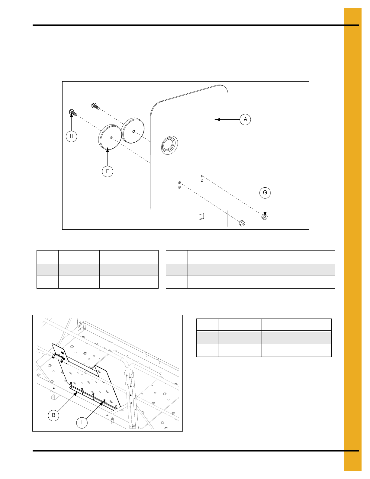
Hatch Deck Door -
Magnets
Install Hatch (Continued)
4. Slide two (2) magnets (16-0092) onto each MS #6 x 3/4" FHS flat head screw (S-7166). Position the
magnet so the screw head is countersunk into the magnet. (See Figure 9C.)
5. Insert screws with magnets through the hatch door and fasten with the #6 flange nut (S-10133).
Figure 9C
Ref # Part # Description Ref # Part # Description
A HP1624HDD Hatch Deck Door G S-2010 Nylock Nut #10-24 ZN Grade 2
F HP1648MAG Magnet
H Screw, MS #10-24 x 5/8" HWHS ZN Grade 2
6. Align holes on the hatch hinge with holes along the deck opening closest to the kick plates. Install
the hatch door to the decking using 3/8" x 3/4" bolts (S-7105) and nuts. (See Figure 9D.)
Ref # Part # Description
B HP1624HH Hatch Hinge
I S-7105 3/8" x 3/4" Bolt
PNEG-1807CE CE Compliant 16"-24" Bucket Elevator Platform and Ladder “X” Series 71
Figure 9D
Page 72

9. Install Hatch
Hatch Deck Door - Clamps
Install Hatch (Continued)
7. Assemble pipe clamps (S-10139) to the magnet mount hatch bracket (HP1648LMM). Insert
3/8" x 3/4" carriage bolts through the magnet mount hatch bracket, 1/2" flat washer and pipe clamp.
Fasten with 3/8" nut. (See Figure 9E.)
8. Attach pipe clamp around intermediate handrail and fasten loosely with bolts. Open hatch plate and
slide clamp along handrail until it lines up with the magnets on the hatch plate. Tighte n clamp to rail.
Figure 9E
Ref # Part # Description
J HP1648LMM Magnet Mount Hatch Bracket
K S-10139 Pipe Clamp 1" O.D. 3/8" Holes with Screw
L 3/8" Nut
M 1/2" Flat Washer
N 3/8" x 3/4" Carriage Bolt
72 PNEG-1807CE CE Compliant 16"-24" Bucket Elevator Platform and Ladder “X” Series
Page 73

10. 4 x 5 Distributor Platform (Optional)
16" Distributor Deck Top Clamp Band
Chapter 10: 4 x 5 Distributor Platform (Optional)
The distributor platform is optional and only used on bucket elevators that have a distributor spout. The
platform is used to access the distributor for maintenance and control adjustments. The platform should
be located below the distributor head. NOTE: That the clamp installation to the trunking is different for
16", 24" and the 30"-36" but the rest of the assembly is the same.
16"-24" Clamp Band Installation
Attach Top Clamp Band to Trunking (for 24" Instructions, see Steps 3 and 4.)
1. Slide rods of clamp rod weldment into inside set of holes of clamp bands for 16" assembly. Fasten
together using four (4) 1/2" hex flange nuts.
2. Line up the holes on the clamp strut with the set of holes closest to the bend on both of the
16"-24" long clamp clips and fasten all three (3) together using fou r (4) 1/2" x 1" b olts and nuts. This
will create the clamp strut assembly.
3. Assemble the clamp band weldment, clamp channel and clamp strut assembly at one time around
the trunking. Place clamp rod weldment assembly around the trunking leg and line up holes on
16"-24" long clips and clamp channel with the outside set of holes on the clamp rod weldment.
Fasten all three (3) together using six (6) 1/2" x 1" bolts and nuts.
4. Line up the holes located at the end of the distributor support channels with the holes at the end of
the 16"-24" long clamp clips. Fasten the support channels to the long clamp clips using four (4)
1/2" x 1" bolts and nuts. (See Figure 10A.)
Ref # Part # Description Ref # Part # Description
A GSB30210X Distributor Support Channel (+5") E DSP16005 Clamp Rod Weldment
B DSP1624TRF Long Clamp Clip for 16"-24"
C DSP16001 Clamp Channel G S-7935 1/2" x 1" Bolt
D DSP16002 Distributor Clamp Band
PNEG-1807CE CE Compliant 16"-24" Bucket Elevator Platform and Ladder “X” Series 73
Figure 10A
F DSP1624RFS Clamp Strut for 16" Trunking
H S-8 506 1/2" Flange Nut
Page 74

10. 4 x 5 Distributor Platform (Optional)
16" Distributor Deck Bottom Clamp Band
16" Attach Bottom Clamp Band to Trunking (for 24" Instructions, see Steps 2
3.)
and
1. Slide rods of clamp rod weldment into inside set of holes of clamp bands for 16" assembly. Fasten
together using four (4) 1/2" hex flange nuts.
2. Line up the holes on one of the clamp struts with the set of holes closest to the bend on both of the
16"-24" long clamp clips and fasten all three (3) together using four (4) 1/2" x 1" bolt and nut s. Tighten
only finger tight. Next orient the brace channels so the bends face outwards and line up the brace
channel holes with the holes located at the end of the long clamp clips and the remaining clamp strut.
Fasten all five (5) parts together using four (4) 1/2" x 1" bolt and nuts. Tighten finger tight. This will
make up the brace channel assembly.
3. Assemble the clamp rod weldment, clamp channel and brace channel assembly at same time around
the trunking. Place clamp rod weldment assembly around the trunking leg and line up holes on
16"-24" long clips and clamp channel with the outside set of holes on the clamp rod weldment.
Fasten all three (3) together using six (6) 1/2" x 1" bolts and nuts. (See Figure 10B.)
Figure 10B
Ref # Part # Description Ref # Part # Description
A GSB30147 Brace Channel E DSP16002 Distributor Clamp Band
B S-8506 1/2" Hex Flange Nut
C DSP1624TRF Long Clamp Clip fo r 16"-24" G S-7935 1/2" x 1" Bolt
D DSP16001 Clamp Channel
74 PNEG-1807CE CE Compliant 16"-24" Bucket Elevator Platform and Ladder “X” Series
F DSP16005 Clamp Rod Weldment
H DSP1624TRF S Clamp Strut for 16"-24" Trunking
Page 75

10. 4 x 5 Distributor Platform (Optional)
24" Distributor Deck Top Clamp Band
24" Attach Top Clamp Band to Trunking
1. Slide rods of clamp rod weldment into inside set of holes of clamp bands for 24" assembly. Fasten
together using four (4) 1/2" hex flange nuts.
2. Line up the holes on the support channels with the inside set of holes on the 16"-24" long clamp clips
and fasten all four (4) together using eight (8) 1/2" x 1" bolt and nuts.
3. Assemble the 16"-24" long clamp assembly, clamp channel and clamp rod assembly at same time
around the trunking. Place clamp rod weldment assembly around the trunking leg and line up holes
on 16"-24" long clips and clamp channel with the outside set of holes on the clamp rod we ldment.
Fasten all three (3) together using six (6) 1/2" x 1" bolts and nuts. (See Figure 10C.)
Ref # Part # Description
A GSB30210X Distributor Support Channel (+5")
B DSP1624TRF Long Clamp Clip for 16"-24"
C DSP16001 Clamp Channel
D DSP16002 Distributor Clamp Band
E DSP16005 Clamp Rod Weldment
F S-8506 1/2" Hex Flange Nut
G S-7935 1/2" x 1" Bolt
H S-8506 1/2" Flange Nut
PNEG-1807CE CE Compliant 16"-24" Bucket Elevator Platform and Ladder “X” Series 75
Figure 10C
Page 76
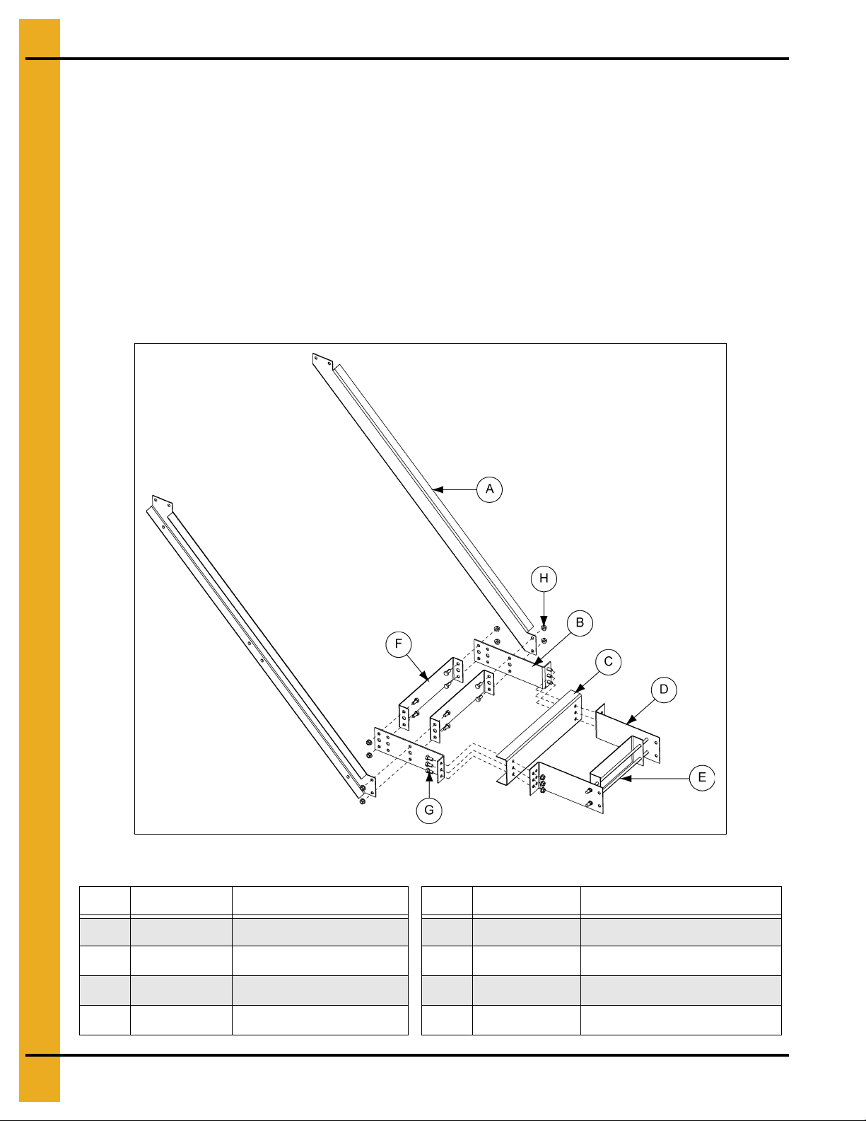
10. 4 x 5 Distributor Platform (Optional)
24" Distributor Deck Bottom Clamp Band
24" Attach Bottom Clamp Band to Trunking and Knee Brace
1. Slide rods of clamp rod weldment into inside set of holes of clamp bands for 16" assembly. Fasten
together using four (4) 1/2" hex flange nuts.
2. Orient the brace channels so the bends face outwards and line up the brace channel holes with the
holes located near the middle of the 16"-24" long clamp clips. Line up the clamp strut with the same
set of holes as the brace channel and 16"-24" long clamp clip. Fasten all five (5) together using
four (4) 1/2" x 1" bolts and nuts. Attach remaining clamp strut to the end of the 16"-24" clamp clip.
Tighten only finger tight. (See Figure 10D.)
3. Assemble the clamp rod weldment, clamp channel and brace channel assembly at same time around
the trunking. Place clamp rod weldment assembly around the trunking leg and line up holes on
16"-24" long clips and clamp channel with the outside set of holes on the clamp rod weldment.
Fasten all three (3) together using six (6) 1/2" x 1" bolts and nuts.
Figure 10D
Ref # Part # Description Ref # Part # Description
A GSB30147 Brace Channel E DSP16005 Clamp Rod Weldment
B DSP1624TRF Long Clamp Clip for 16"-24" F DSP1624TRFS Clamp Strut for 16"-24" Trunking
C DSP16001 Clamp Channel G S-7935 1/2" x 1" Bolt
D DSP16002 Distributor Clamp Band H S-8506 1/2" Hex Flange Nut
76 PNEG-1807CE CE Compliant 16"-24" Bucket Elevator Platform and Ladder “X” Series
Page 77

10. 4 x 5 Distributor Platform (Optional)
Distributor Platform Cross Support
NOTE: Right hand shown.
Assemble Supports (16"-24")
1. Attach brace channels to the sides of the support channels using four (4) 1/2" x 1" bolts and nuts.
Angle the knee braces across the bottom sides of the brace channels and attach using four (4)
1/2" x 1" bolts and nuts.
2. Assemble the cross supports to the bottom side of the support channels using the end and middle
sets of holes on the support channels using four (4) 1/2" x 1" bolts and nuts. (See Figure 10E.)
3. Assemble the external platform support (DSP1648EPS) to the end of the three (3) cross supports
using six (6) 1/2" x 1" bolts and nuts. (See Figure 10F on Page 78.)
NOTE: For 24" installation the lower knee brace will use the second hole on the brace and the second
hole up from the bottom on the brace channel. (See Figure 10G on Page 78.)
Ref # Part # Description Ref # Part # Description
A GSB30210X Distributor Support Channel (+5") D GSB30148 Knee Brace
B DSP1648CS Distributor Platform Cross Support E S-7935 1/2" x 1" Bolt
C GSB30147 Brace Channel F S-8506 1/2" Hex Flange Nut
PNEG-1807CE CE Compliant 16"-24" Bucket Elevator Platform and Ladder “X” Series 77
Figure 10E Distributor Platform Cross Support
Page 78

10. 4 x 5 Distributor Platform (Optional)
Distributor External Platform Support
NOTE: Right hand shown.
Distributor Platform
Knee Brace
Assemble Supports (16"-24") (Continued)
Figure 10F Distributor External Platform Support
Ref # Part # Description Ref # Part # Description
B DSP1648CS Distributor Platform Cross Support F S-8506 1/2" Hex Flange Nut
E S-7935 1/2" x 1" Bolt G DSP1648EPS
Ref # Part # Description
C GSB30147 Brace Channel
D GSB301 48 Knee Brace
E S-7935 1/2" x 1" Bolt
Distributor External
Platform Support
Figure 10G 24" Distributor Platform Knee Brace
78 PNEG-1807CE CE Compliant 16"-24" Bucket Elevator Platform and Ladder “X” Series
Page 79

10. 4 x 5 Distributor Platform (Optional)
NOTE: Right hand shown.
Assemble Decking and “W” Corner Post
1. Align A6 and A8 on platform decking weldment with A6 and A8 on the external platform supports.
2. Install platform decking weldment to the platform support channels using twenty four (24)
1/2" x 1" bolt and nuts. (See Figure 10H.)
3. Attach the flange of the toe board short side to the bottom of the 18" decking using two (2)
1/2" x 1" bolt and nuts. Then attach 18" decking to the external platform support using one
1/2" x 1" bolt and nut. (See Figure 10J on Page 80.)
4. Align flange of end toe board along the bottom of decking. Connect end toe board to decking using
1/2" x 1" bolts and nuts. (See Figure 10I on Page 80.)
5. Install the corner “W” post at the same time as the toe board filler plate. Attach toe board filler plate
to the decking toe boards located across from the entrance. Attach the flat end first using two (2)
5/16" x 3/4" flange bolts and nuts. Then line up the holes of the toe board filler plate with the decking
toe board, while also aligning the holes of the “W” post on the corner. Fasten all three (3) together
with four (4) 5/16" x 3/4" flange bolts and nuts. (See Figure 10K on Page 81.)
Ref # Part # Description Ref # Part # Description
A GSB30141X Platform Deck Weldment C S-7935 1/2" x 1" Bolt
B DSP1648EPS Distributor External Platform Support D S-8506 1/2" Hex Flange Nut
PNEG-1807CE CE Compliant 16"-24" Bucket Elevator Platform and Ladder “X” Series 79
Figure 10H
Page 80

10. 4 x 5 Distributor Platform (Optional)
NOTE: Right hand shown.
Distributor Deck Toe Board
NOTE: Right hand shown.
Assemble Decking and “W” Corner Post (Continued)
Figure 10I
Ref # Part # Description Ref # Part # Description
E DSP1648DEX 18" Decking G S-7935 1/2" x 1" Bolt
F GSB36256 Toe Board Short Side
H S-8506 1/2" Hex Flange Nut
Figure 10J 16" Distributor Platform Toe Board
Ref # Part # Description
G S-7935 1/2" x 1" Bolt
H S-8506 1/2" Hex Flange Nut
I GSB30136X End Toe Board
80 PNEG-1807CE CE Compliant 16"-24" Bucket Elevator Platform and Ladder “X” Series
Page 81

10. 4 x 5 Distributor Platform (Optional)
Distributor Deck Corner Post
NOTE: Right hand shown.
Assemble Decking and “W” Corner Post (Continued)
PNEG-1807CE CE Compliant 16"-24" Bucket Elevator Platform and Ladder “X” Series 81
Figure 10K Distributor Platform Corner Post
Ref # Part # Description
J HP1648HWP Head/Distributor “W” Post
K GSB30142X Toe Board Filler Plate
L S-6606 5/16" x 3/4" Flange Bolt
M S-10268 5/16" Hex Flange Nut
Page 82

10. 4 x 5 Distributor Platform (Optional)
NOTE: Right hand shown.
Install Handrail Posts - Non-Entrance Side
1. Install the remaining two (2) “W” corner posts to the corners on the non-entrance side of th e decking
using four (4) 5/16" x 3/4" flange bolts and nuts per post.
2. Install platform post (HP1648HCP) to the inside corner of the decking near the entrance to the
platform using four (4) 5/16" x 3/4" flange bolts and nuts.
3. Attach side posts (HP1648HP) to the decking at the entrance to the platform using two (2)
5/16" x 3/4" flange bolts and nuts per post. (See Figure 10L.)
4. Install distributor handrail support to the side post on the inside, located closest to the trunking
through holes 3 and 4 counting from the top of the post. Use two (2) 5/16" x 3 /4" flange bolts and nuts
to fasten in place. (See Figure 10L.)
Figure 10L
Ref # Part # Description Ref # Part # Description
A HP1648HP Head/Distributor Side Post D DSP1648HS Distributor Handrail Support
B HP1648HWP Head/Distributor “W” Post E S-6606 5/16" x 3/4" Flange Bolt
C HP1648HCP Platform Post F S-10268 5/16" Flange Nut
82 PNEG-1807CE CE Compliant 16"-24" Bucket Elevator Platform and Ladder “X” Series
Page 83

10. 4 x 5 Distributor Platform (Optional)
NOTE: Right hand shown.
Install Intermediate Handrails
1. Insert small intermediate handrail into the large intermediate handrails to create telescoping rails.
Cut 30" off one small intermediate and one large intermediate rail to fit at entrance. Adjust all rails to
the proper length and install to the posts using the 5
two (2) 5/16" x 3/4" flange bolts and nuts per each telescoping tube. (See Figure 10M.)
th
hole down from the top. Fasten in place using
Ref # Part # Description Ref # Part # Description
A LDR-4087 L arge Intermedia te Handrail D S-10268 5/16" Flange Nut
B LDR-4088 Small Intermediate Handrail E Cut Small Intermediate Rails
C S-6606 5/16" x 3/4" Flange Bolt F Cut Large Intermediate Rails
PNEG-1807CE CE Compliant 16"-24" Bucket Elevator Platform and Ladder “X” Series 83
Figure 10M
Page 84

10. 4 x 5 Distributor Platform (Optional)
NOTE: Right hand shown.
Install Safety Bar Cross Supports
NOTE: Safety cage bars (LDR-5171BE) are used as tie braces in this installation.
1. Install safety bar cross supports from the decking toe board to the rail posts using two (2)
5/16" x 3/4" flange bolts and nuts per each cross bar support. (See Figure 10N.)
Figure 10N
Ref # Part # Description
A LDR-5171BE Braces
B S-6606 5/16" x 3/4" Flange Bolt
C S-10268 5/16" Flange Nut
84 PNEG-1807CE CE Compliant 16"-24" Bucket Elevator Platform and Ladder “X” Series
Page 85

10. 4 x 5 Distributor Platform (Optional)
NOTE: Right hand shown.
Install Top Handrails
1. Attach handrails to the posts using four (4) 5/16" x 3/4" flange bolts and nuts per handrail.
(See Figure 10O.)
Ref # Part # Description Ref # Part # Description
A HP1648HDH 64.126" Handrail E DSP1648HNT 43.2" Handrail
B S-7877 5/16" x 2" Bolt F DSP1648HSSG 10.5" Handrail
C S-10268 5/16" Flange Nut G HP1624HFH 59.479" Handrail
D DSP1648HIP 45.2" Handrail
PNEG-1807CE CE Compliant 16"-24" Bucket Elevator Platform and Ladder “X” Series 85
Figure 10O
Page 86

10. 4 x 5 Distributor Platform (Optional)
Safety Gate Package (Optional)
IMPORTANT: Attach the platform gate bracket to the gate before attaching it to the inside platform post
using 5/16" hardware.
Attach safety gate assembly to intermediate platform door bracket using 5/16" bolt (S-1196), 5/16"
flat washer (S-845) and 5/16" flange nut (S-10268).
Attach intermediate platform door bracket to two (2) safety gate side posts (HP1648HP) using 5/16" bolt
(S-1196), 5/16" flat washer (S-845) and 5/16" flange nut (S-10268). (See Figure 10P.)
Figure 10P
Ref # Part # Description
A S-1 196 5/16" Bolt
B S-845 5/16" Flat Washer
C S-10268 5/16" Flange Nut
86 PNEG-1807CE CE Compliant 16"-24" Bucket Elevator Platform and Ladder “X” Series
Page 87

11. Warranty
9101239_1_CR_rev8.DOC (revised January 2014)
GSI Group, LLC Limited Warranty
The GSI Group, LLC (“GSI”) warrants products which it manufactures to be free of defects in materials and workmanship
under normal usage and conditions for a period of 12 months after sale to the original end-user or if a foreign sale,
14 months from arrival at port of discharge, whichever is earlier. The end-user’s sole remedy (and GSI’s only obligation)
is to repair or replace, at GSI’s option and expense, products that in GSI’s judgment, contain a material defect in materials
or workmanship. Expenses incurred by or on behalf of the end-user without prior written authorization from the GSI
Warranty Group shall be the sole responsibility of the end-user.
Warranty Extensions:
The Limited Warranty period is extended for the following products:
Product Warranty Period
Performer Series Direct Drive Fan Motor 3 Years * Warranty prorated from list price:
AP Fans and Flooring
AP and Cumberland Flex-Flo/Pan Feeding System Motors 2 Years
Cumberland
Feeding/Watering
Systems
Grain Systems
Grain Systems
Farm Fans
Zimmerman
All Fiberglass Housings Lifetime
All Fiberglass Propellers Lifetime
Feeder System Pan Assemblies 5 Years **
Feed Tubes (1-3/4" and 2.00") 10 Years *
Centerless Augers 10 Years *
Watering Nipples 10 Years *
Grain Bin Structural Design 5 Years
Portable and Tower D ryers 2 Years
Portable and Tower Dryer Frames and
Internal Infrastructure †
5 Years
0 to 3 years - no cost to end-user
3 to 5 years - end-user pays 25%
5 to 7 years - end-user pays 50%
7 to 10 years - end-user pays 75%
** Warranty prorated from list price:
0 to 3 years - no cost to end-user
3 to 5 years - end-user pays 50%
† Motors, burner components
and moving parts not included.
Portable dryer screens included.
Tower dryer screens not included.
GSI further warrants that the portable and tower dryer frame and basket, excluding all auger and auger drive components,
shall be free from defects in materials for a period of time beginning on the twelfth (12
and continuing until the sixtieth (60
th
) month from the date of purchase (extended warranty period). During the extended
th
) month from the date of purchase
warranty period, GSI will replace the frame or basket components that prove to be defective under normal conditions
of use without charge, excluding the labor, transportation, and/or shipping costs incurred in the performance of this
extended warranty.
Conditions and Limitations:
THERE ARE NO WARRANTIES THAT EXTEND BEYOND THE LIMITED WARRANTY DESCRIPTION SET FORTH
ABOVE. SPECIFICALLY, GSI MAKES NO FURTHER WARRANTY OF ANY KIND, EXPRESS OR IMPLIED,
INCLUDING, WITHOUT LIMITATION, WARRANTIES OF MERCHANTABILITY OR FITNESS FOR A PARTICULAR
PURPOSE OR USE IN CONNECTION WITH: (I) PRODUCT MANUFACTURED OR SOLD BY GSI OR (II) ANY ADVICE,
INSTRUCTION, RECOMMENDATION OR SUGGESTION PROVIDED BY AN AGENT, REPRESENTA TIVE OR
EMPLOYEE OF GSI REGARDING OR RELATED TO THE CONFIGURATION, INSTALLATION, LAYOUT, SUITABILITY
FOR A PARTICULAR PURPOSE, OR DESIGN OF SUCH PRODUCTS.
GSI shall not be liable for any direct, indirect, incidental or consequential damages, including, without limitation, loss of
anticipated profits or benefits. The sole and exclusive remedy is set forth in the Limited Warranty, which shall not exceed
the amount paid for the product purchased. This warranty is not transferable and applies only to the original end-user. GSI
shall have no obligation or responsibility for any representations or warranties made by or on behalf of any dealer, agent
or distributor.
GSI assumes no responsibility for claims resulting from construction defects or unauthorized modifications to products
which it manufactured. Modifications to products not specifically delineated in the manual accompanying the equipment at
initial sale will void the Limited Warranty.
This Limited Warranty shall not extend to products or parts which have been damaged by negligent use, misuse, alteration,
accident or which have been improperly/inadequately maintained. This Limited Warranty extends solely to products
manufactured by GSI.
Prior to installation, the end-user has the responsibility to comply with federal, state and local codes which apply to the
location and installation of products manufactured or sold by GSI.
PNEG-1807CE CE Compliant 16"-24" Bucket Elevator Platform and Ladder “X” Series 87
Page 88

This equipment shall be installed in accordance with
the current installation codes and applicable
regulations, which should be carefully followed in all
cases. Authorities having jurisdiction should be
consulted before installations are made.
GSI Group
1004 E. Illinois St.
Assumption, IL 62510-0020
Phone: 1-217-226-4421
Fax: 1-217-226-4420
www.gsiag.com
Copyright © 2014 by GSI Group
Printed in the USA
GSI is a worldwide brand of AGCO Corporation.
CN-312209
 Loading...