

GSI Group PNEG-1451 Installation Manual
PNEG-1451
Ladder, Safety Cage and
Platform Assembly for
GSI Hopper Tanks
Installation Manual
PNEG-1451
Date: 10-21-13

2 PNEG-1451 Ladder, Safety Cage and Platform for Hopper Tanks

Table of Contents
Contents
Chapter 1 Introduction ..........................................................................................................................................5
Chapter 2 Safety .....................................................................................................................................................6
Safety Guidelines ...... ... ... .... .................................................................................................................. 6
Safety Instructions ..................... ... .... ............................................. ... ... ... .... ... ... ..................................... 7
Chapter 3 Safety Decals ........................................................................................................................................9
Roof Damage Warning and Disclaimer ................................................................................................. 9
Chapter 4 General Detail Information ................................................................................................................12
Extension Rail Installation ......... ... .... ... ... ... .......................................................................................... 12
Ladder Section Assembly ................................................................................................................... 13
Ladder Standoff Detail ........................................................................................................................ 14
Extension Angle Hole Detail ................................................................................................................ 15
Safety Cage Hoop Bracket Assembly ................................................................................................. 16
Chapter 5 2.66" Corrugated Commercial Hopper Tank 4-9 Rings ...................................................................20
2.66" Commercial Hopper Tank (NCHT) Ladder and Platform Layout 4-9 Rings ............................... 20
NCHT Ladder, Safety Cage and Platform Instructions 4-9 Rings ....................................................... 22
Eave Starter Bracket Installation ..................................................................................................... 22
Location of Field Drilled Holes for Eave Ladder Starter Brackets ................................................ ... 23
Eave Starter Bracket and Ladder Assembly with Safety Cage ....................................................... 24
Eave Adjustable Braces .................................................................................................................. 27
Eave Platform Mounting Angle Installation...................................................................................... 28
Right Hand Platform and Platform Support Assembly ........................................................................ 29
Eave Safety Cage Hoop Assembly ..................................................................................................... 31
Adapter Assembly Detail ..................................................................................................................... 32
Vertical Supports ................................. ... ... ... .... ... ... ............................................. .... ... ... ...................... 33
32" and 48" Safety Cage .................................. ............................................. ... ... .... ... ... ... ... ................ 33
Access Door Platform Mounting Angle Installation ............................................................................. 34
Left Hand Platform and Platform Support Assembly ........................................................................... 35
Access Door Safety Cage Hoop Assembly ......................................................................................... 37
24"-48" Safety Cage Bell Sections ...................... ... ... .... ... ... ... .... ... ... ... ... ............................................. 38
Ladder Support Detail ......................................................................................................................... 39
Chapter 6 2.66" Corrugated Commercial Hopper Tank 10-22 Rings ...............................................................42
2.66" Commercial Hopper Tank (NCHT) Ladder and Platform Layout 10-22 Rings ........................... 42
NCHT Ladder, Safety Cage and Platform Instructions 10-22 Rings ................................................... 46
Eave Starter Bracket Installation ..................................................................................................... 46
Location of Field Drilled Holes for Eave Ladder Starter Brackets ................................................ ... 46
Eave Starter Bracket and Ladder Assembly with Safety Cage ....................................................... 47
Eave Adjustable Braces .................................................................................................................. 50
Eave Platform Mounting Angle Installation...................................................................................... 51
Right Hand Platform and Platform Support Assembly ........................................................................ 52
Eave Safety Cage Hoop Assembly ..................................................................................................... 54
Adapter Assembly Detail ..................................................................................................................... 55
Vertical Supports ................................. ... ... ... .... ... ... ............................................. .... ... ... ...................... 56
48" Safety Cage ........................ ... .... ... ............................................. ... ... .... ......................................... 56
24"-48" Safety Cage Bell Sections ...................... ... ... .... ... ... ... .... ... ... ... ... .... ... ... ... ................................ 57
Intermediate Platform Mounting Angle Installation .............................................................................. 58
Location of Field Drilled Holes for Intermediate Ladder Starter Brackets ........................................... 59
PNEG-1451 Ladder, Safety Cage and Platform for Hopper Tanks 3

Table of Contents
Intermediate Starter Bracket and Ladder Assembly with Safety Cage ............................................... 60
Intermediate and Base Safety Cage Hoop Assembly ......................................................................... 61
Base Platform Mounting Angle Installation ......................................................................................... 62
Location of Field Drilled Holes for Base Ladder Starter Brackets ....................................................... 63
Base Starter Bracket and Ladder Assembly with Safety Cage ........................................................... 64
Access Door Platform Mounting Angle Installation ............................................................................. 65
Left Hand Platform and Platform Support Assembly ........................................................................... 66
Access Door Safety Cage Hoop Assembly ......................................................................................... 68
Ladder Support Detail ...... .... ... ... ... .............................................. ... ... ... ... .... ... ..................................... 69
Chapter 7 4.00" Corrugation Farm Commercial Hopper Tanks (FCHT) 4-6 Rings .........................................72
4.00" Farm Commercial Hopper Tank Ladder and Platform Layout 4-6 Rings ................................... 72
FCHT Ladder, Safety Cage and Platform Instructions 4-6 Rings ....................................................... 74
Eave Starter Bracket Installation ..................................................................................................... 74
Location of Field Drilled Holes for Eave Ladder Starter Brackets ........................................ ... ... ... .. 75
Eave Starter Bracket and Ladder Assembly with Safety Cage ....................................................... 76
Eave Adjustable Braces .................................................................................................................. 79
Eave Platform Mounting Angle Installation...................................................................................... 80
Right Hand Platform and Platform Support Assembly ........................................................................ 81
Eave Safety Cage Hoop Assembly...................................................................................................... 83
Adapter Assembly Detail ..................................................................................................................... 84
Vertical Supports ................................................................................................................................. 85
44" and 48" Safety Cage ......................... ............................................................. ............................... 85
Access Door Platform Mounting Angle Installation ............................................................................. 86
Left Hand Platform and Platform Support Assembly ........................................................................... 87
Access Door Safety Cage Hoop Assembly ......................................................................................... 89
24"-48" Safety Cage Bell Sections ...................................................................................................... 90
Ladder Support Detail ...... .... ... ... ... .............................................. ... ... ... ... .... ... ..................................... 91
Chapter 8 4.00" Corrugation Farm Commercial Hopper Tank (FCHT) 7-9 Rings ........... ....................... .........94
4.00" Farm Commercial Hopper Tank (FCHT) Ladder and Platform Layout ...................................... 94
FCHT Ladder, Safety Cage and Platform Instructions 7-9 Rings ....................................................... 95
Eave Starter Bracket Installation ..................................................................................................... 95
Location of Field Drilled Holes for Eave Ladder Starter Brackets ........................................ ... ... ... .. 95
Eave Starter Bracket and Ladder Assembly with Safety Cage .......................................................96
Eave Adjustable Braces .................................................................................................................. 99
Eave Platform Mounting Angle Installation.................................................................................... 100
Eave Platform and Platform Support Assembly .......................... ... ... ... ... .... ... ... ... .... ......................... 101
Eave Safety Cage Hoop Assembly ................................ ... ... ... .... ... ... ... ... .... ... ... ... ............................. 103
Adapter Assembly Detail ................................................................................................................... 104
Vertical Supports ............................................................................................................................... 105
48" Safety Cage ................................................................................................................................ 105
24"-48" Safety Cage Bell Sections .................................................................................................... 106
Access Door/Base Platform Mounting Angle Installation .................................................................. 107
Location of Field Drilled Holes for Base/Access Door Ladder Starter Brackets ................................ 108
Base/Access Door Starter Bracket and Ladder Assembly with Safety Cage .................................... 109
Access Door Platform and Platform Support Assembly .................... ................................................ 110
Base Platform and Platform Support Assembly .......................... ... ... ... ... .... ... ... ... .... ......................... 112
Access Door/Base Safety Cage Hoop Assembly . ... ... ................................................. ... ................... 114
Access Door/Base Platform Vertical Supports .................................................................................. 115
Ladder Support Detail ...... .... ... ... ... .............................................. ... ... ... ... .... ... ................................... 116
Chapter 9 Warranty ............................................................................................................................................117
4 PNEG-1451 Ladder, Safety Cage and Platform for Hopper Tanks

1. Introduction
READ THIS MANUAL carefully to learn how to properly use and install equipment. Failure to do so could
result in personal injury or equipment damage.
INSPECT the shipment immediately upon arrival. The customer is responsible for ensuring that all
quantities are correct. The customer should report and note any damage or shortage on the bill of
lading to justify their claim to the transport company.
THIS MANUAL SHOULD BE CONSIDERED a permanent part of your equipment and should be easily
accessible when needed.
This warranty provides you the assurance that the company will back its products when defects appear
within the warranty period. In some circumstances, the company also provides field improvements, often
without charge to the customer, even if the product is out of warranty. Should the equipment be abused,
or modified to change its performance beyond the factory specifications, the warranty will become void
and field improvements may be denied.
PNEG-1451 Ladder, Safety Cage and Platform for Hopper Tanks 5

2. Safety
This is the safety alert symbol. It is used to alert you
to potential personal injury hazards. Obey all safety
messages that follow this symbol to avoid possible
injury or death.
WARNING indicates a hazardous situation which, if not
avoided, could result in death or serious injury.
CAUTION, used with the safety alert symbol, indicates a
hazardous situation which, if not avoided, could result in
minor or moderate injury.
NOTICE is used to address practices not related to
personal injury.
DANGER indicates a hazardous situation which, if not
avoided, will result in death or serious injury.
Safety Guidelines
This manual contains information that is important for you, the owner/operator, to know and understand.
This information relates to protecting personal safety and preventing equipment problems. It is the
responsibility of the owner/operator to inform anyone operating or working in the area of this equipment
of these safety guidelines. To help you recognize this information, we use the symbols that are defined
below. Please read the manual and pay attention to these sections. Failure to read this manual and its
safety instructions is a misuse of the equipment and may lead to serious injury or death.
DANGER
WARNING
CAUTION
NOTICE
6 PNEG-1451 Ladder, Safety Cage and Platform for Hopper Tanks
2. Safety
Follow Safety Instructions
Carefully read all safety messages in this manual and
safety signs on your machine. Keep signs in good
condition. Replace missing or damaged safety signs. Be
sure new equipment components and repair parts include
the current safety signs. Replacement safety signs are
available from the manufacturer.
Learn how to operate the machine and how to use controls
properly. Do not let anyone operate without instruction.
Keep your machinery in proper working condition.
Unauthorized modifications to the machine may impair
the function and/or safety and affect machine life.
If you do not understand any part of this manual or need
assistance, contact your dealer.
Read and Understand Manual
Install Equipment Properly
This equipment shall be installed in accordance with the
current installation codes and applicable regulations which
should be carefully followed in all cases. Authorities having
jurisdiction should be consulted before installations
are made.
Follow Building Codes
Safety Instructions
Our foremost concern is your safety and the safety of others associated with this equipment. We want to
keep you as a customer. This manual is to help you understand safe operating procedures and some
problems which may be encountered by the operator and other personnel.
As owner and/or operator, it is your responsibility to know what requirements, hazards, and precautions
exist, and to inform all personnel associated with the equipment or in the area. Safety precautions may be
required from the personnel. Avoid any alterations to the equipment. Such alterations may produce a very
dangerous situation where SERIOUS INJURY or DEATH may occur.
This equipment shall be installed in accordance with the current installation codes and applicable
regulations which should be carefully followed in all cases. Authorities having jurisdiction should be
consulted before installations are made.
PNEG-1451 Ladder, Safety Cage and Platform for Hopper Tanks 7
2. Safety
Stay Clear of Hoisted Equipment
Always use proper lifting/hoisting equipment when
assembling or disassembling equipment.
Do not walk or stand under hoisted equipment.
Always use sturdy and stable supports when needed
for installation.
Crush Hazard
Prepare for Emergencies
Be prepared if fire starts.
Keep a first aid kit and fire extinguisher handy.
Keep emergency numbers for doctors, ambulance service,
hospital, and fire department near your telephone.
Keep Emergency Equipment
Quickly Accessible
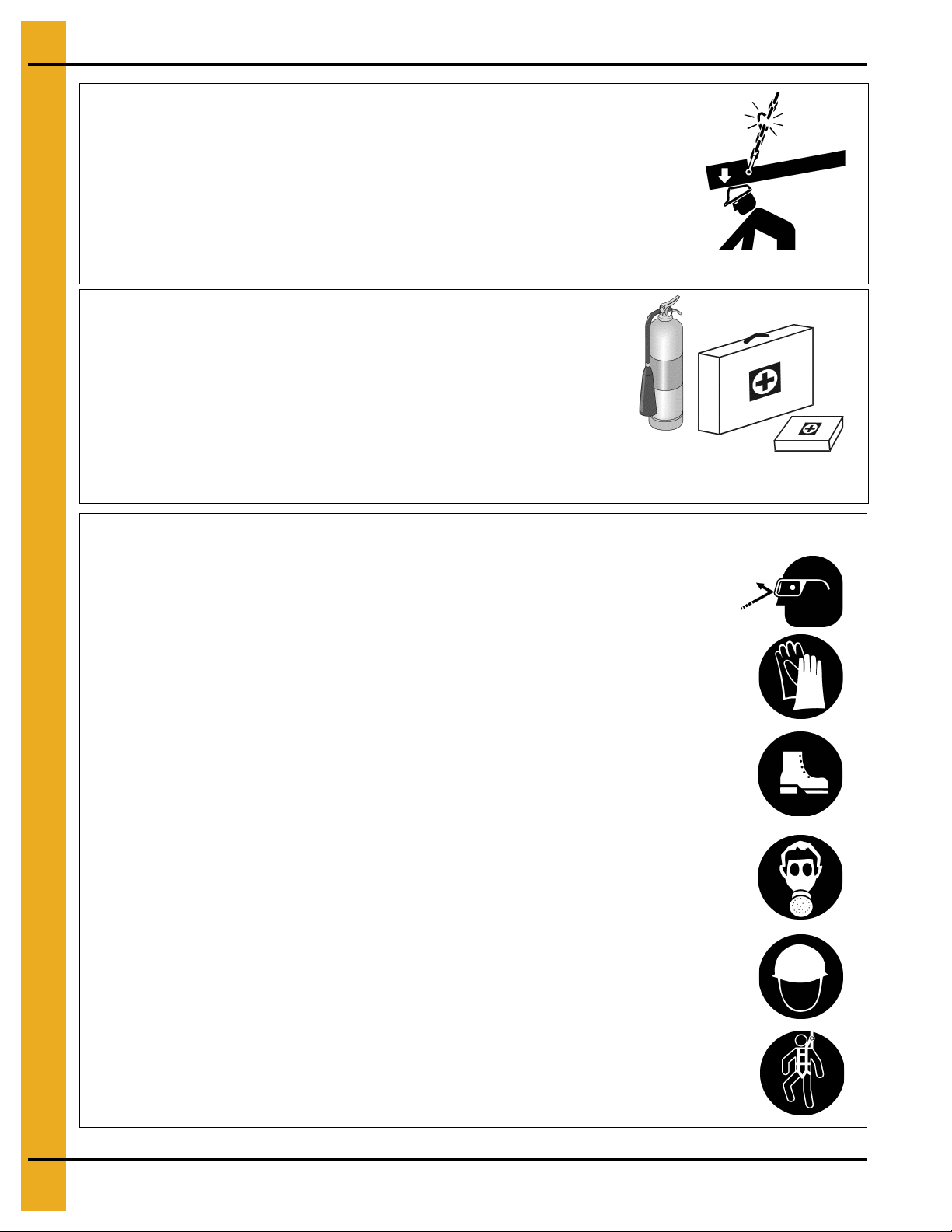
Wear Protective Clothing
Wear close-fitting clothing and safety equipment appropriate
to the job.
Remove all jewelry.
Tie long hair up and back.
Wear safety glasses at all times to protect eyes from debris.
Wear gloves to protect your hands from sharp edges on plastic
or steel parts.
Wear steel-toed boots to help protect your feet from falling
debris. Tuck in any loose or dangling shoestrings.
A respirator may be needed to prevent breathing potentially
toxic fumes and dust.
Wear a hard hat to help protect your head.
Wear appropriate fall protection equipment when working at
elevations greater than six feet (6').
Eye Protection
Gloves
Steel-Toed Boots
Respirator
Hard Hat
Fall Protection
8 PNEG-1451 Ladder, Safety Cage and Platform for Hopper Tanks
3. Safety Decals
The manufacturer does not warrant any roof damage caused by excess ive v acuum or internal
pressure from fans or other air moving systems. Adequate ventilation and/or “makeup air”
devices should be provided for all powered air handling systems. The manufacturer does not
recommend the use of downward flow systems (suction). Severe roof damage can result from
any blockage of air passages. Running fans durin g high humidity/cold weather conditions can
cause air exhaust or intake ports to freeze.
Roof Damage Warning and Disclaimer
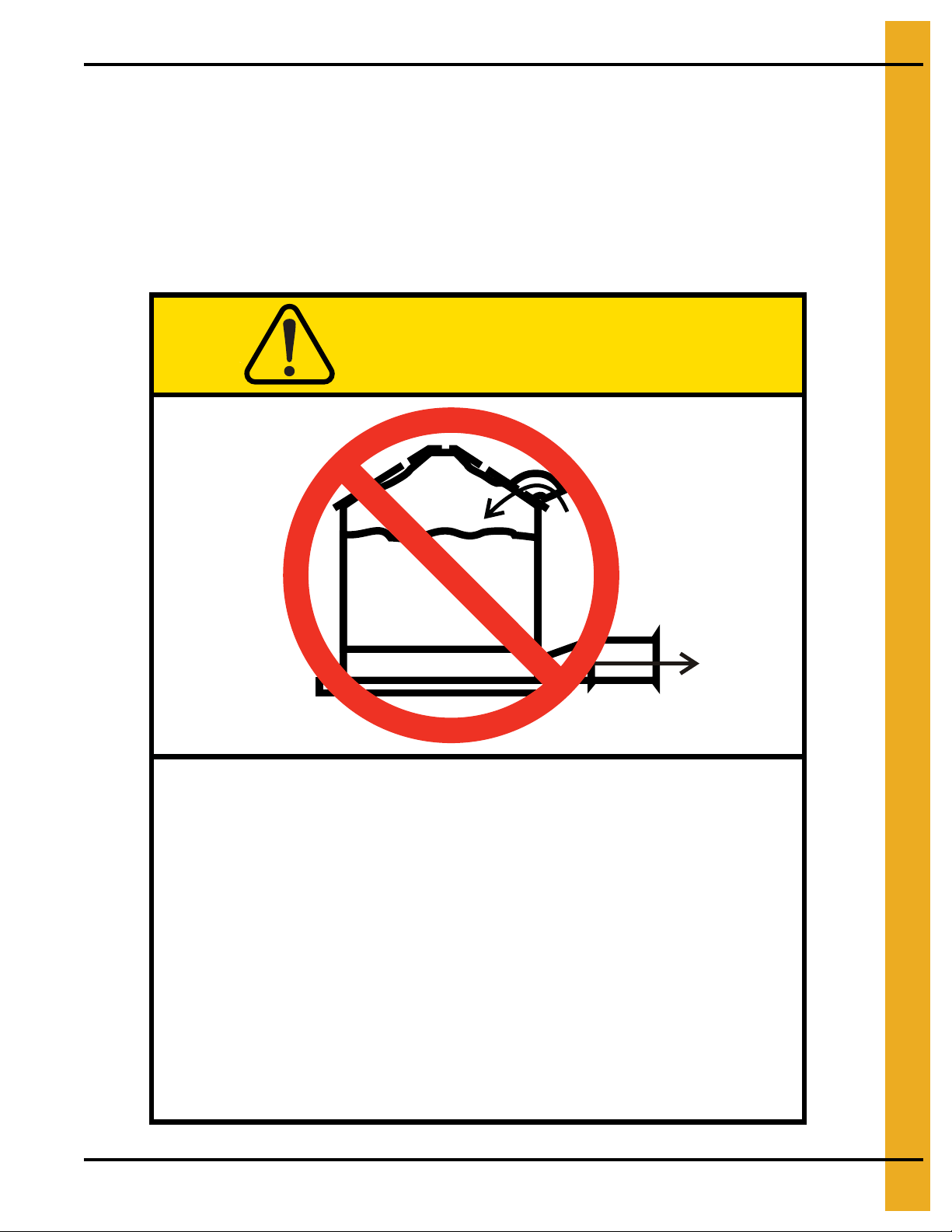
CAUTION
Excessive vacuum (or pressure) may
damage roof. Use positive aeration
system. Make sure all roof vents are
open and unobstructed. Start roof
fans when supply fans are started.
Do not operate when conditions exist
that may cause roof vent icing.
GSI Group, Inc. 217-226-4421
PNEG-1451 Ladder, Safety Cage and Platform for Hopper Tanks 9
DC-969
3. Safety Decals
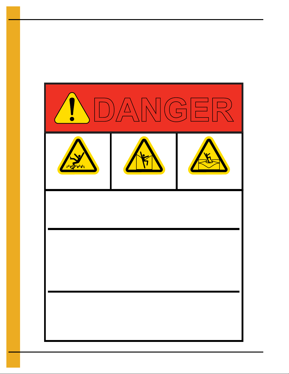
Rotating flighting will
kill or dismember.
Flowing material will
trap and suffocate.
Crusted material will
collapse and suffocate.
DANGER
Keep clear of all augers.
DO NOT ENTER this bin!
If you must enter the bin:
1. Shut off and lock out all power.
2. Use a safety harness and safety line.
3. Station another person outside the bin.
4. Avoid the center of the bin.
5. Wear proper breathing equipment or respirator.
Failure to heed these
warnings will result in
serious injury or death.
DC-GBC-1A
GSI GROUP, INC. 217-226-4421
ATTENTION: The decal shown below should be present on the outside of t he door cover of the 2 ring on
the 24" porthole door cover, and on the roof manway cover. If a decal has been damaged or is missing in
any of these locations, contact the manufacturer for a free replacement decal.
GSI Decals
1004 E. Illinois St.
Assumption, IL. 62510
Phone: 1-217-226-4421
10 PNEG-1451 Ladder, Safety Cage and Platform for Hopper Tanks
3. Safety Decals
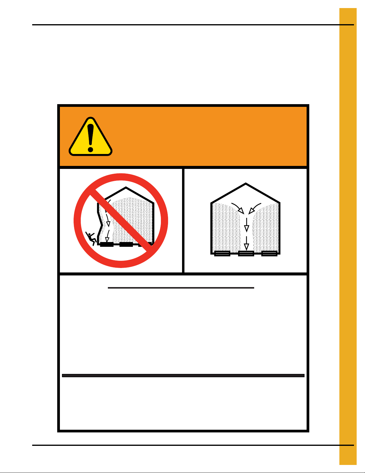
WARNING
GSI GROUP, INC. 217-226-4421
1. Use CENTER FLOOR OUTLET ONLY until NO grain
remains above this outlet.
2. Side floor outlets to be used ONLY when above
condition is satisfied.
3. Lock all side floor outlets to avoid accidental
premature use.
4. See manufacturers instructions for proper use of
factory supplied sidedraw (wall) discharge systems.
UNLOADING INSTRUCTIONS:
Failure to heed these warnings
could result in serious injury, death,
structural damage or collapse of tank.
DC-GBC-2A
ATTENTION: The decal shown below should be present on the outside of the door cover of the 2 ring on
the 24" porthole door cover, and on the roof manway cover. If a decal has been damaged or is missing in
any of these locations, contact the manufacturer for a free replacement decal.
GSI Decals
1004 E. Illinois St.
Assumption, IL. 62510
Phone: 1-217-226-4421
PNEG-1451 Ladder, Safety Cage and Platform for Hopper Tanks 11
4. General Detail Information
Extension Rail Installation
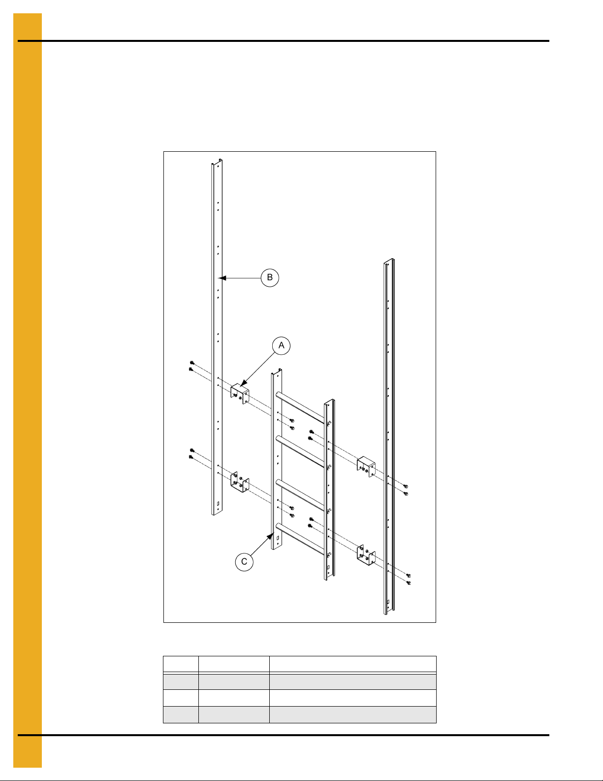
All ladder systems that include a safety cage must also include ladder extension rails attached to the top
four foot (4') ladder section (C). Start by bolting the spacer brackets (A) through the top and bottom set o f
holes in the top ladder section (C). Then, attach the extension rails (B) to the spacer brackets (A) as shown
in Figure 4A. When installed correctly, the bottom of the extension rail (B) should be flush with the bottom
of the top ladder section (C). Use 5/16" x 3/4" bin bolts for all connections.
Figure 4A Ladder Extension
Ref # Part # Description
A LDR-4403 Spacer Bracket
B 8' Extension Rail
C Top Ladder Section
12 PNEG-1451 Ladder, Safety Cage and Platform for Hopper Tanks
4. General Detail Information
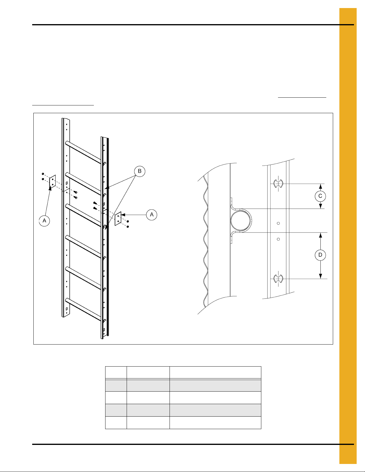
Ladder Section Assembly
Two (2) splice plates (LDR-4317) (A) are required to attach each ladder section (B). The head of the bolt
should be to the inside of the ladder with the splice plate (A) on the outside as shown in Figure 4B.
Use 5/16" x 3/4" bolts for all connections.
NOTE: With most installations, the last ladder section (B) installed to reach the ground, the base or the
intermediate platform should be cut to fit.
Wind rings must be installed in relation to the ladder rungs as shown here, to ensure compliance with
O.S.H.A. regulations.
Figure 4B
Ref # Part # Description
A LDR-4317 Splice Plates
B Ladder Sections
C 1-1/2" Minimum
D 4-1/2" Minimum
PNEG-1451 Ladder, Safety Cage and Platform for Hopper Tanks 13
4. General Detail Information
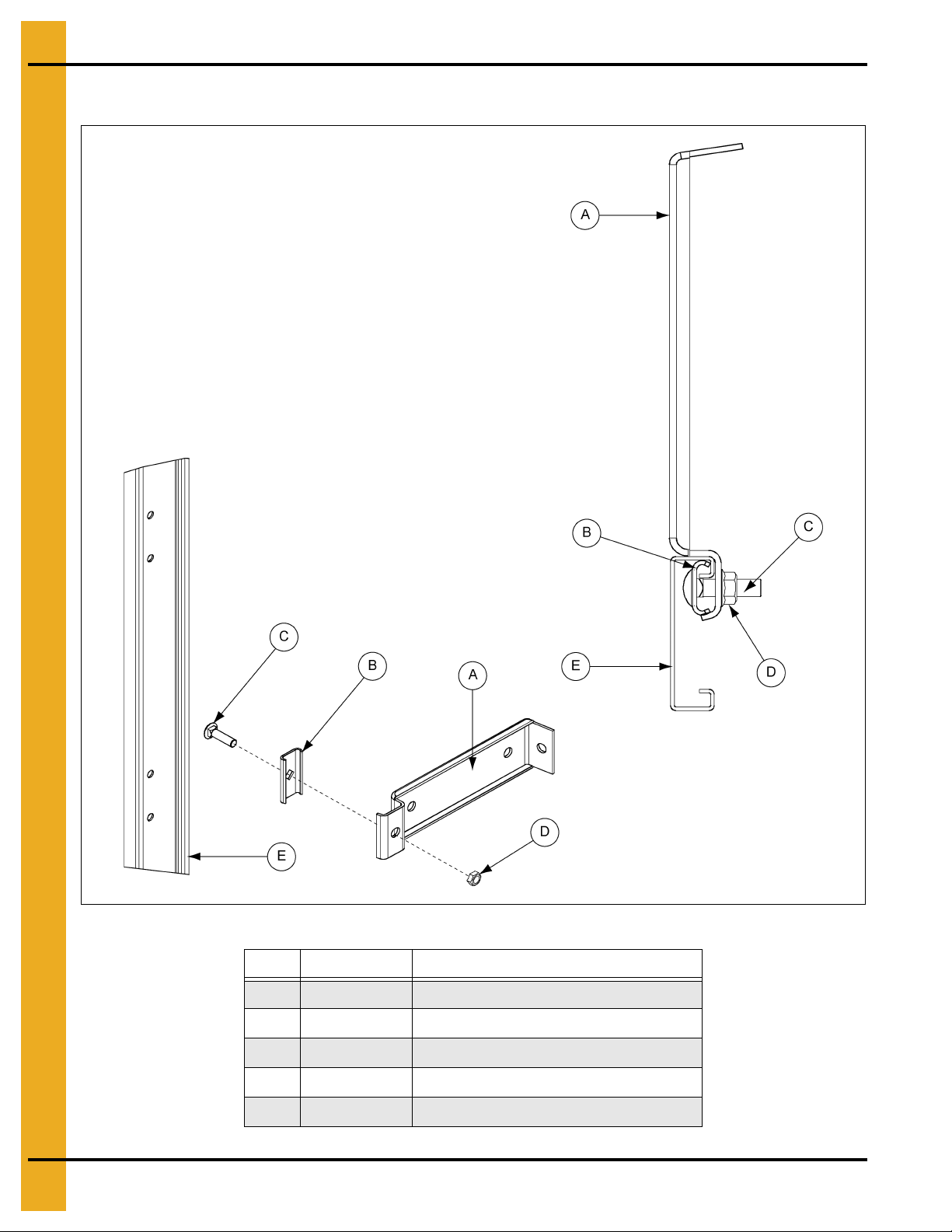
Ladder Standoff Detail
Figure 4C Assembled View from Top of Bin
Ref # Part # Description
A LDR-4314 Standoff Bracket
B LDR-4198 Standoff Wedge
C S-3550 5/16" x 1" Carriage Bolt
D S-3611 5/16" Flange Nut
E Ladder
14 PNEG-1451 Ladder, Safety Cage and Platform for Hopper Tanks
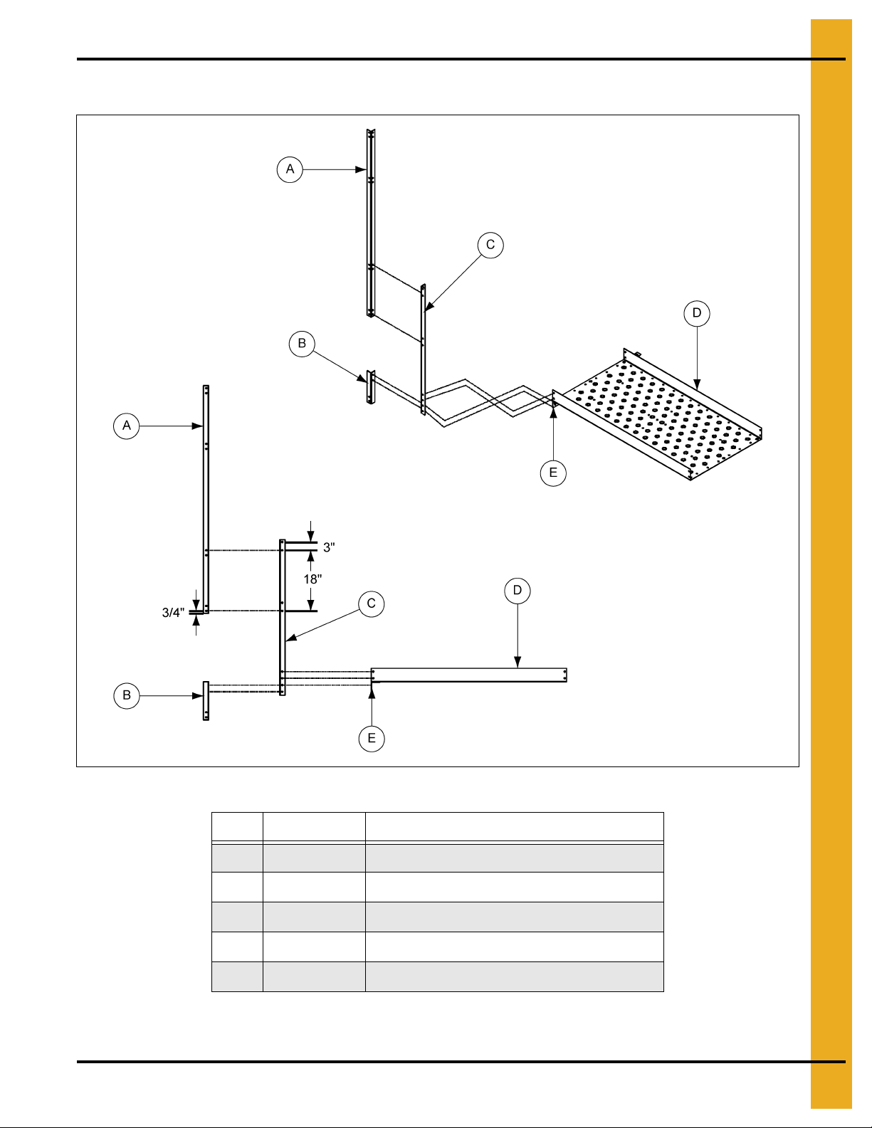
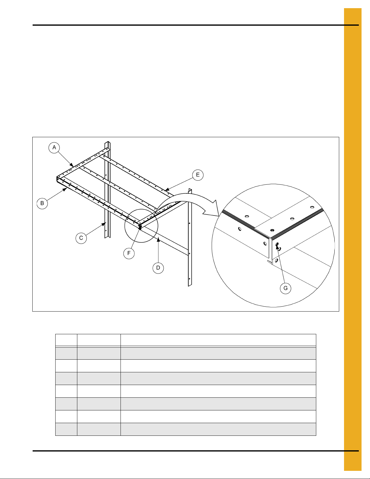
Extension Angle Hole Detail
4. General Detail Information
Figure 4D Assembly View
Ref # Part # Description
A LS-6775 67-1/2" Extension Angle
B LS-6776 1 1-5/16" Vertical Adapter Angle
C LS-6621 46" Vertical Entrance Angle
D LS-6703 Platform
E TDP-5011 29-3/4" Platform Support
NOTE: Platform (D) and platform support (E) shown for reference only. See platform assembly detail
on Page 52 for complete installation instructions for these parts.
PNEG-1451 Ladder, Safety Cage and Platform for Hopper Tanks 15
4. General Detail Information
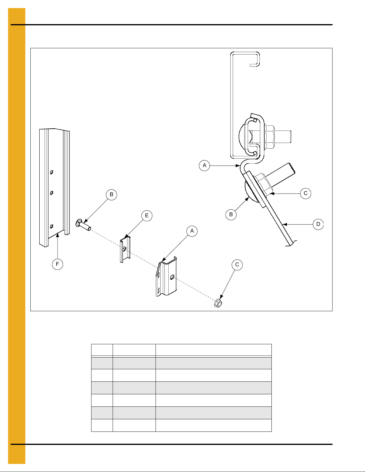
Safety Cage Hoop Bracket Assembly
Figure 4E Assembled View from Top of Bin
NOTE: Leave bolt loose until cage hoop half has been attached.
Ref # Part # Description
A LDR-4199 Cage Hoop Bracket
B S-3550 5/16" x 1" Carriage Bolt
C S-3611 5/16" Flange Nut
D LDR-4201 Safe ty Cage H oop Half
E LDR-4198 Standoff Wedge
F Ladder
16 PNEG-1451 Ladder, Safety Cage and Platform for Hopper Tanks
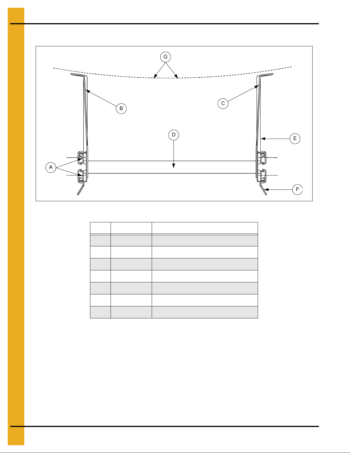
4. General Detail Information
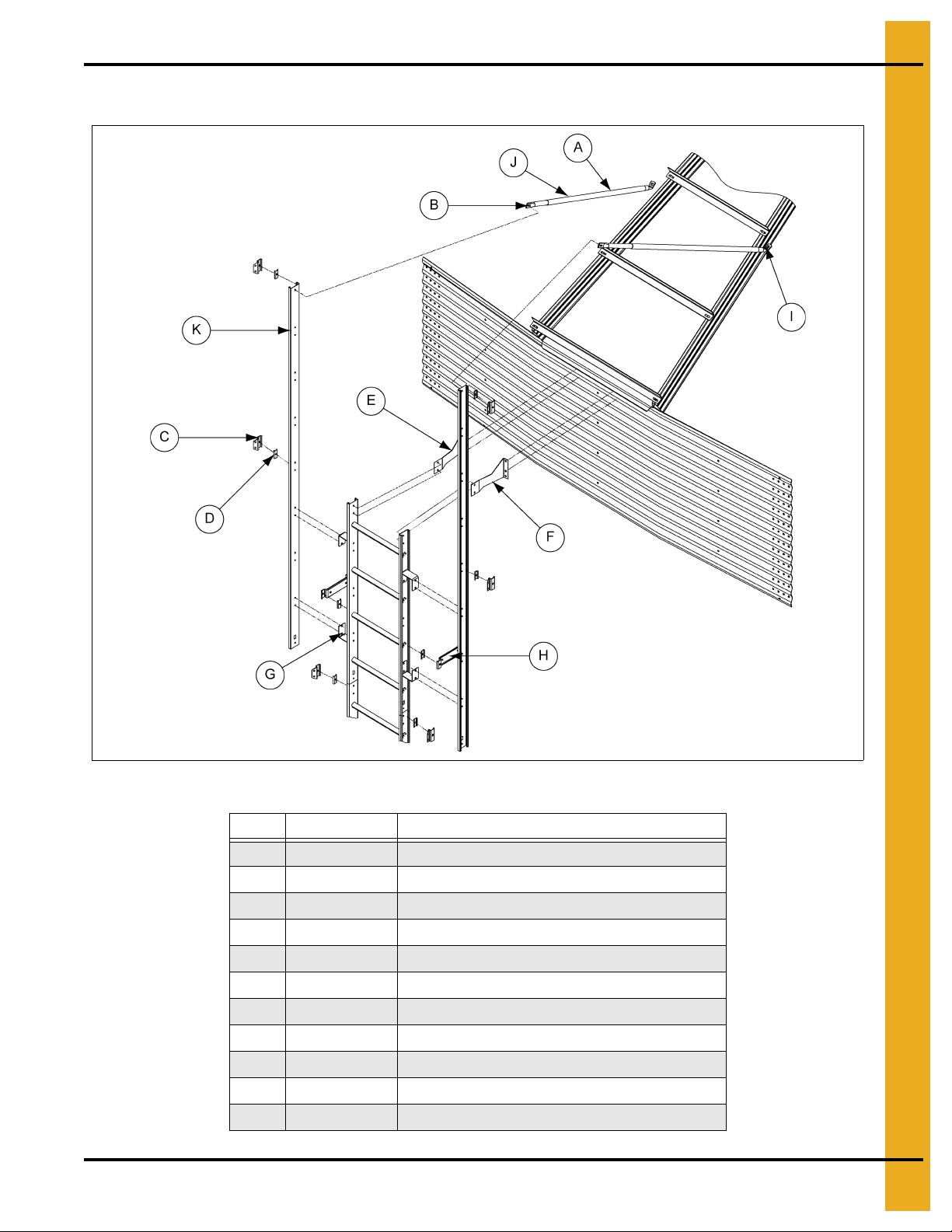
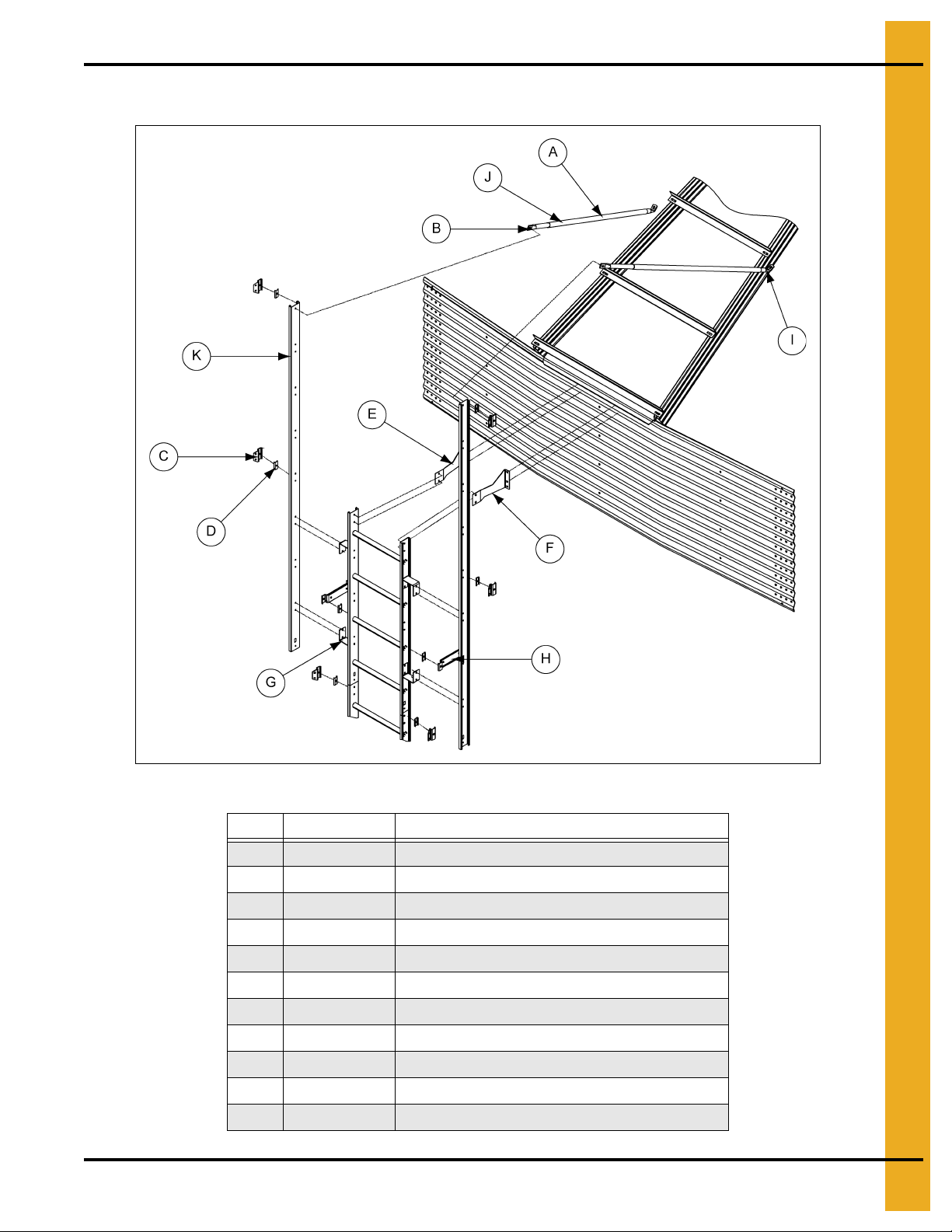
Safety Cage Hoop Bracket Assembly (Continued)
Figure 4F
Ref # Part # Description
A LS-6615 Center Tube
B LS-6616 End Tube
C LDR-4199 Safety Cage Hoop Bracket
D LDR-4198 Standoff Wedge
E LDR-4346 L.H. Starter Bracket
F LDR-4347 R.H. Starter Bracket
G LDR-4403 Spacer Bracket
H LDR-4314 Standoff Bracket
I Small Tube
J Field Drill 5/16" Holes Four (4) per Brace
K 8' Extension Rail
PNEG-1451 Ladder, Safety Cage and Platform for Hopper Tanks 17

NOTES
18 PNEG-1451 Ladder, Safety Cage and Platform for Hopper Tanks

PNEG-1451 Ladder, Safety Cage and Platform for Hopper Tanks 19
2.66" Corrugated Commercial
Hopper Tank 4-9 Rings
®
5. 2.66" Corrugated Commercial Hopper Tank 4-9 Rings
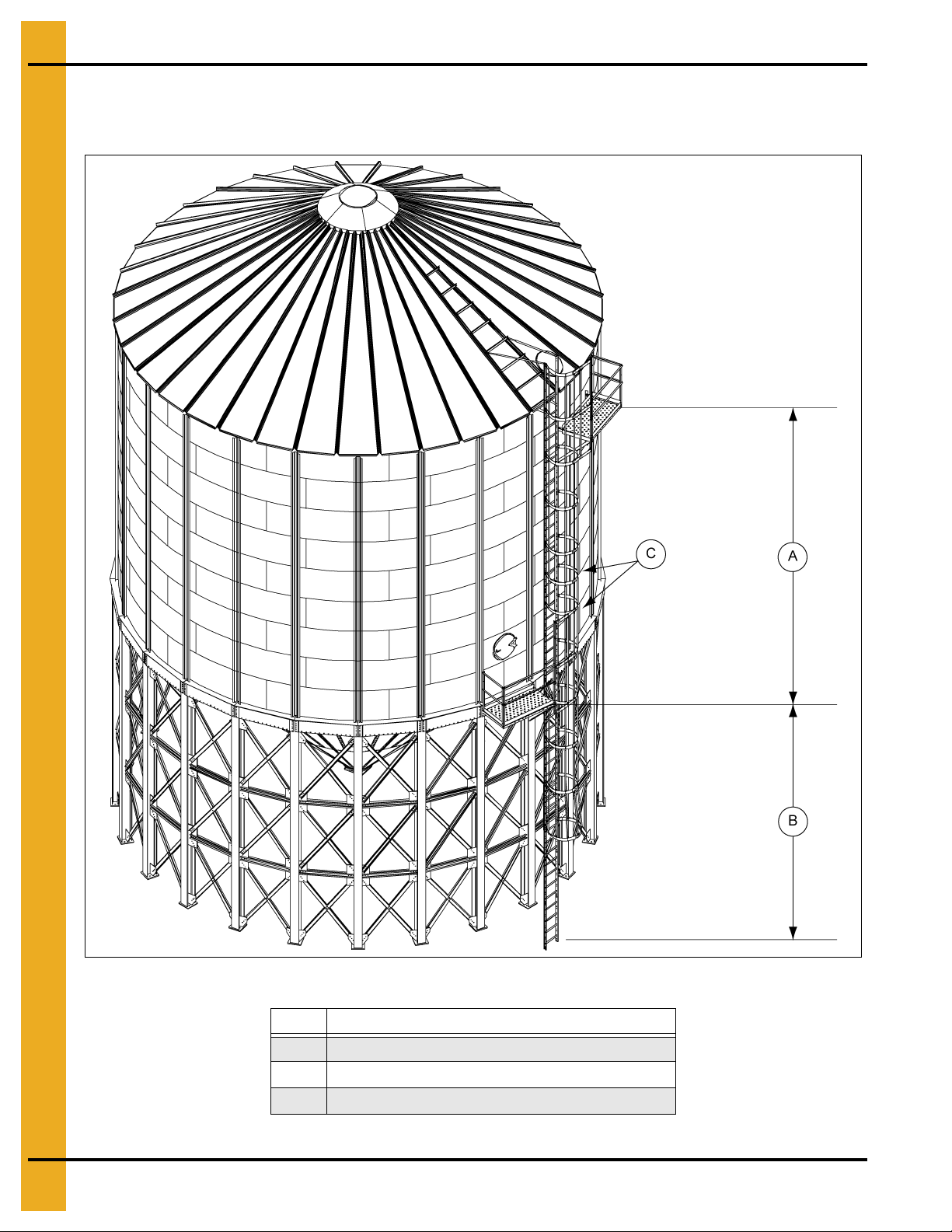
2.66" Commercial Hopper Tank (NCHT) Ladder and Platform
Layout 4-9 Rings
Figure 5A 9 Rings
Ref # Description
A A (Section A)
B B (Section B)
C 32" Safety Cage Sections (See Note on Page 21.)
See Page 21 for platform locations and section listings.
20 PNEG-1451 Ladder, Safety Cage and Platform for Hopper Tanks
5. 2.66" Corrugated Commercial Hopper Tank 4-9 Rings
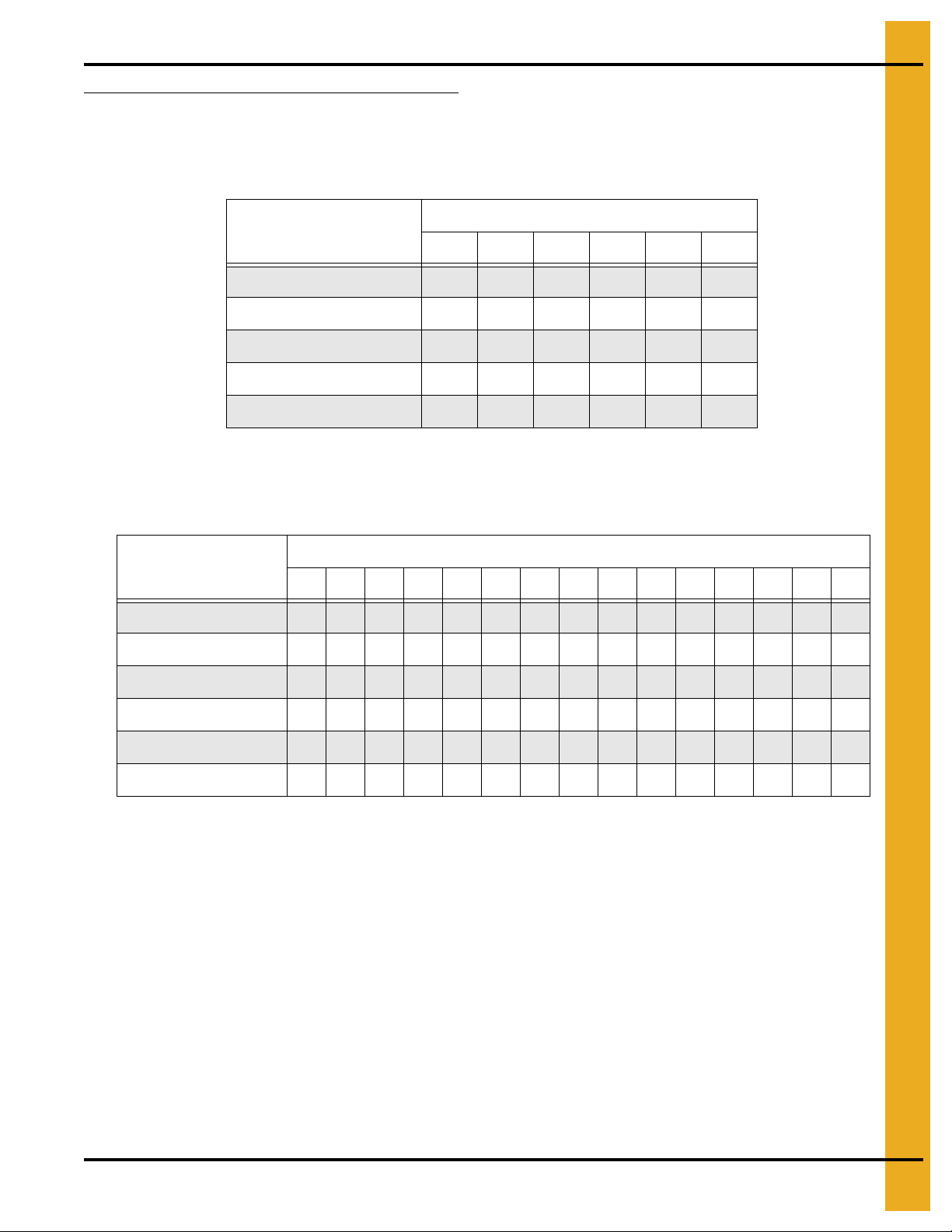
Ladder, Safety Cage and Platform Location Chart
For Section A, find the proper ring grain bin and use the number of ladders and safety cages indicated.
See Chart below (Section A). For Section B, find the proper diameter grain bin and hopper slope, then use
the number of ladders and safety cages indicated. See Chart below (Section B).
Rings
456789
Platform Located in Ring: 2 2 2 2 2 2
4' Ladder Section 3 4 4 5 6 6
Safety Cage 32" Section 0 1 2 0 1 2
Section A
Safety Cage 48" Section 0 0 0 2 2 2
Dimension A 96" 128" 160" 192" 224" 256"
NOTE: The 32" safety cage section must be installed in Section A of the ladder system. DO NOT install
the 32" verticals in the eave or access door safety cage hoop assembly. The eave and access door
safety cage hoop assembly use the 48" verticals.
Diameter
12' 12' 15' 15' 18' 18' 21' 21' 24' 27' 27' 30' 30' 36' 36'
Hopper Slope: 45 60 45 60 45 60 45 60 45 40 45 40 45 40 45
4' Ladder Section 455657576566767
Bell Safety Cage 0 1 0 1 1 1 1 1 1 1 1 1 1 1 1
Safety Cage 48" Section000101020010112
Section B
Bell Safety Cage Size N/A 24" N/A 24" 24" 48" 48" 24" 48" 48" 24" 48" 48" 48" 48"
Dimension B 91" 128" 108" 167" 128" 198" 144" 229" 162" 142" 179" 156" 195" 187" 236"
PNEG-1451 Ladder, Safety Cage and Platform for Hopper Tanks 21

5. 2.66" Corrugated Commercial Hopper Tank 4-9 Rings
NCHT Ladder, Safety Cage and Platform Instructions 4-9 Rings
All grain bin packages, from 4 ring to 9 ring and 12' to 35' diameter, contain the correct components for
assembly. Read and follow the complete instructions for correct placement of parts. Be sure and use the
charts to determine the appropriate number and size parts to be used based upon the number of rin gs in
the bin. Failure to do so may result in an improper fit or shortage of parts. Pay particular attention to the
location of ladders and platforms as they relate to the other equipment and structures in the area.
Eave Starter Bracket Installation
Correct placement of the eave ladder starter bracket is critical to assure proper fit of all ladder co mponents
and to assure the correlation is correct between the platforms for proper installation of the access door
platform. If the eave starter brackets are mislocated, standard installation of the access door platform will
not be possible.
22 PNEG-1451 Ladder, Safety Cage and Platform for Hopper Tanks
5. 2.66" Corrugated Commercial Hopper Tank 4-9 Rings
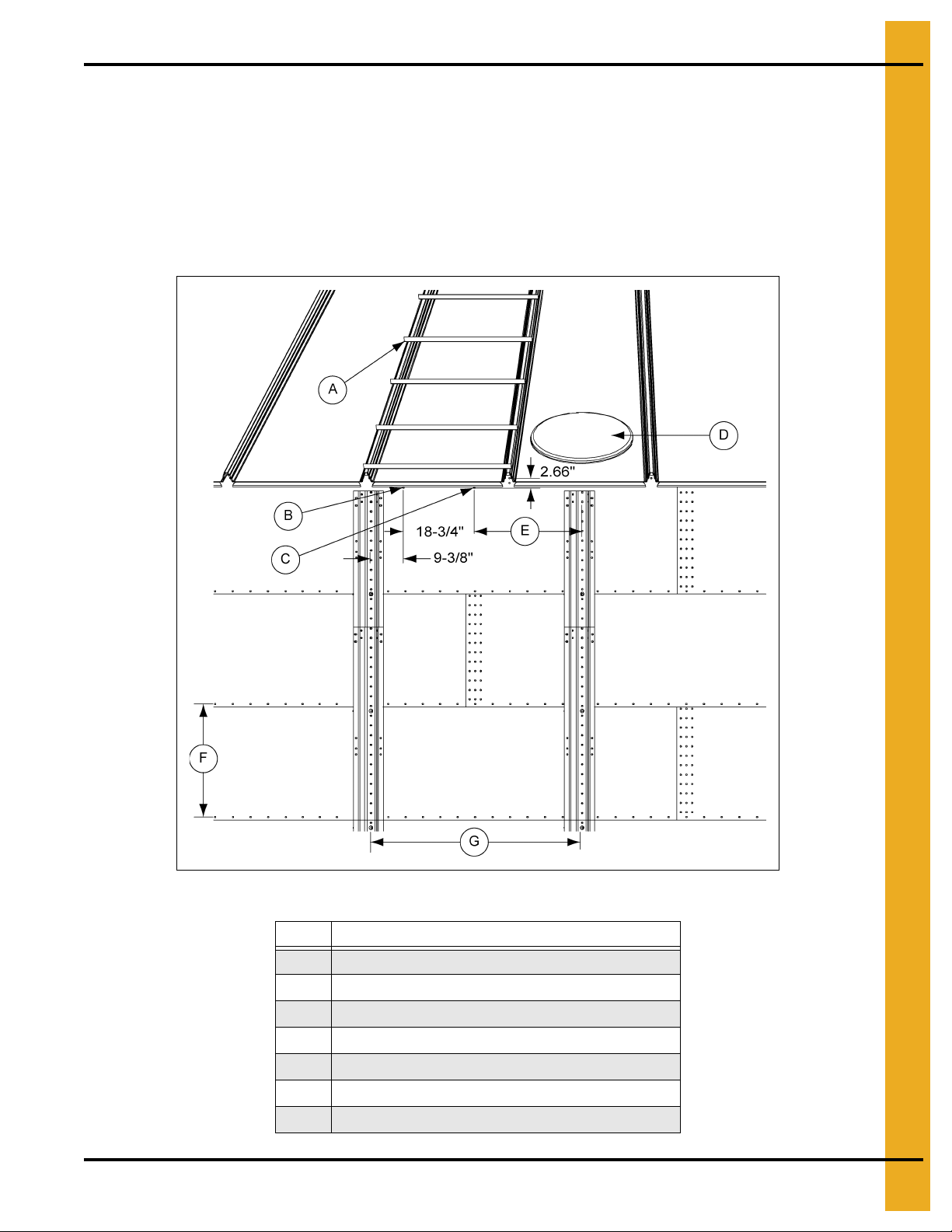
Location of Field Drilled Holes for Eave Ladder Starter Brackets
The starter brackets must be located directly below the roof ladder (A). Before the starter brackets can be
installed, two (2) 3/8" holes must be field drilled 2.66" below and directly in line with the top row of
pre-punched horizontal holes. The first hole, required for the left hand starter bracket, must be located
9-3/8" from the center of the stiffener to the center of the hole as shown in Figure 5B. The second
hole, required for the right hand bracket, must be located 18-3/4" from the center of the first hole. Refer to
Figure 5B for the proper location of the two (2) 3/8" field drilled holes (B and C) required to install the
starter brackets.
Figure 5B
Ref # Description
A Roof Ladder
B Field Drill 3/8" Hole for L.H. Bracket
C Field Drill 3/8" Hole for R.H. Bracket
D Manway Panel
E 28-1/8" Reference
F 32" Typical
G 56-1/4" Typical
PNEG-1451 Ladder, Safety Cage and Platform for Hopper Tanks 23
5. 2.66" Corrugated Commercial Hopper Tank 4-9 Rings
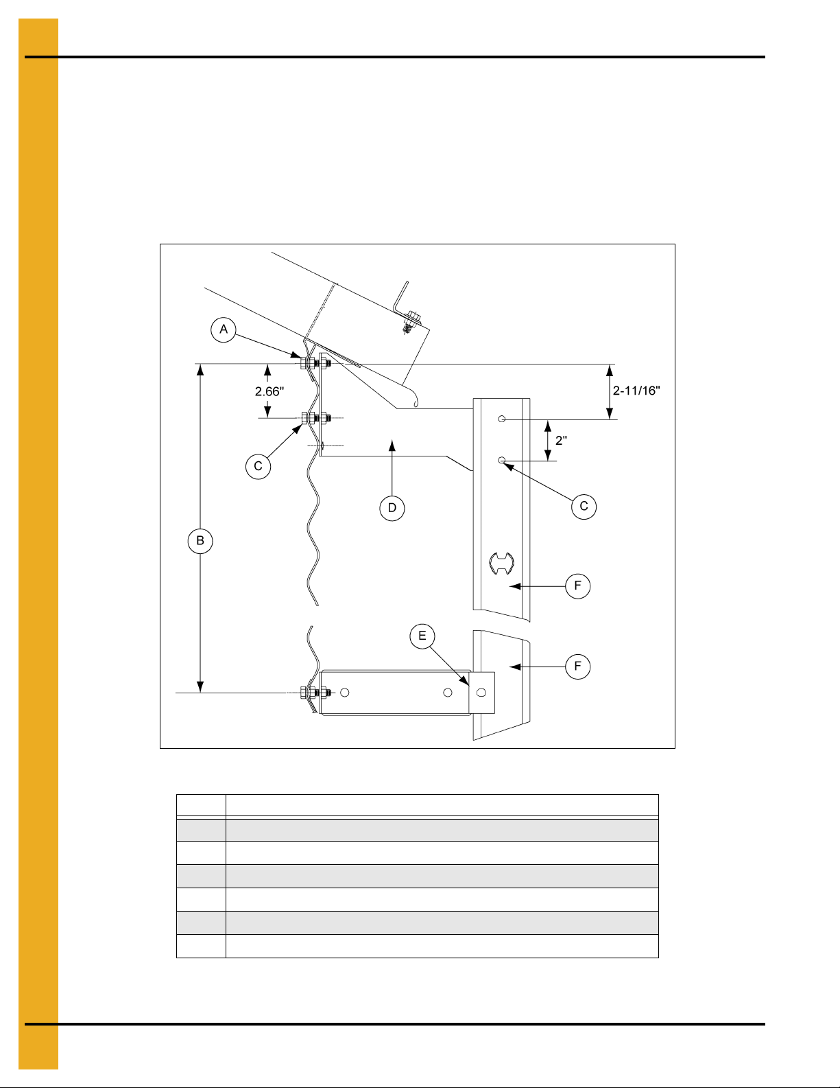
Eave Starter Bracket and Ladder Assembly with Safety Cage
Once the two (2) 3/8" holes have been field drilled, attach the starter brackets (D) to the sidewa ll as shown
in Figure 5C. Check the top ladder section (F) to make sure the ladder rung dimples are to the top. Attach
starter brackets (D) to the top of the ladder. See Figure 4B on Page 13 for the proper installation of
additional ladder sections (F) required. Standoff brackets (E) must be in stalled on the ladder sections (F)
and attached to the sidewall at each horizontal seam and repeated every 32". Use 5/16" x 3/4" bin bolts
for all connections. It is also necessary to field drill a 3/8" hole (C) on the ladder section for each starter
bracket (L.H. and R.H.) (D).
Figure 5C
Ref # Description
A Additional nuts required to support starter bracket and standoff brackets.
B 32" Typical
C Field Drill 3/8" Hole for Starter Bracket
D Starter Bracket (LDR-4346 L.H. and LDR-4347 R.H.)
E Standoff Bracket (LDR-4314)
F 4' Ladder Section
NOTE: Refer to general detail information on Page 12 for additional details for standoff bracket (E) to
ladder assembly and also, 8' extension rail installation (omitted in de tailed figure above for clarity).
24 PNEG-1451 Ladder, Safety Cage and Platform for Hopper Tanks
5. 2.66" Corrugated Commercial Hopper Tank 4-9 Rings
Eave Starter Bracket and Ladder Assembly with Safety Cage (Continued)
Figure 5D
Ref # Part # Description
A LS-6615 Center Tube
B LS-6616 End Tube
C LDR-4199 Cage Hoop Bracket
D LDR-4198 Standoff Wedge
E LDR-4346 L.H. Starter Bracket
F LDR-4347 R.H. Starter Bracket
G LDR-4403 Spacer Bracket
H LDR-4314 Standoff Bracket
I Small Tube
J Field Drill 5/16" Holes Four (4) per Brace
K 8' Extension Rail
PNEG-1451 Ladder, Safety Cage and Platform for Hopper Tanks 25
5. 2.66" Corrugated Commercial Hopper Tank 4-9 Rings
Eave Starter Bracket and Ladder Assembly with Safety Cage (Continued)
Figure 5E Ladder and Bracket as Viewed from Top of Bin
Ref # Part # Description
A LDR-4198 Standoff Wedges
B LDR-4346 L.H. Starter Bracket
C LDR-4347 R.H. Starter Bracket
D LDR-4345 Top Ladder Section
E LDR-4314 Standof f Bracket
F LDR-4199 Safety Cage Hoop Bracket
G Bin
26 PNEG-1451 Ladder, Safety Cage and Platform for Hopper Tanks
5. 2.66" Corrugated Commercial Hopper Tank 4-9 Rings
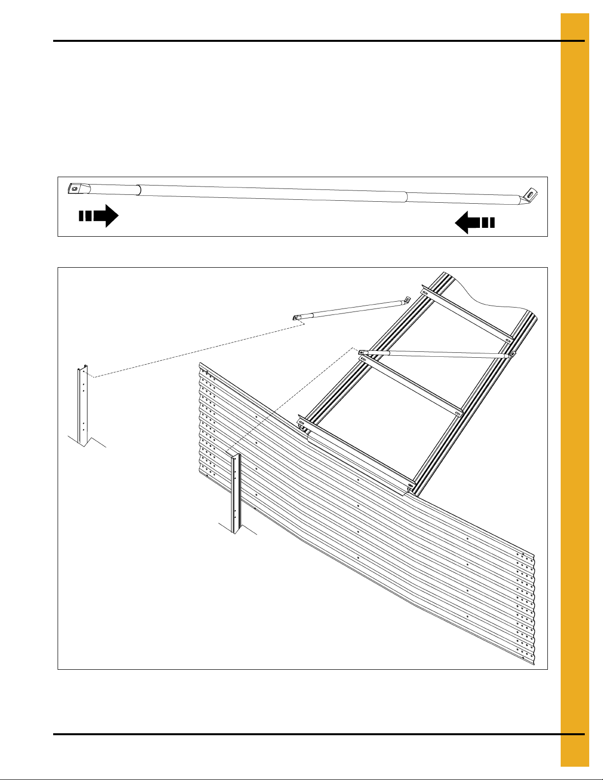
Eave Adjustable Braces
The eave adjustable braces must be attached at this time. An eave adjustable brace is comprised of
one large diameter tube and two (2) smaller diameter tubes. (See Figure 5F.) Slide the smaller tubes
inside the larger tubes and attach one smaller tube to the top of the ladder extension rail. Adjust the other
smaller tube so the bottom of the flattened tube reaches the roof panel. Field drill four (4) 5/16" holes
through both large and small tubes and bolt together using 1/4" x 1-1/2" bolts and nuts. This will prevent
the adjustable braces from slipping. (See Figure 5G.)
NOTE: Refer to Page 24 for proper location of ladder starter brackets.
Figure 5F
Figure 5G
NOTE: Refer to Figure 4A on Page 12 for additional details for standoff bracket to ladder assembly and
cage hoop bracket to ladder.
PNEG-1451 Ladder, Safety Cage and Platform for Hopper Tanks 27
5. 2.66" Corrugated Commercial Hopper Tank 4-9 Rings
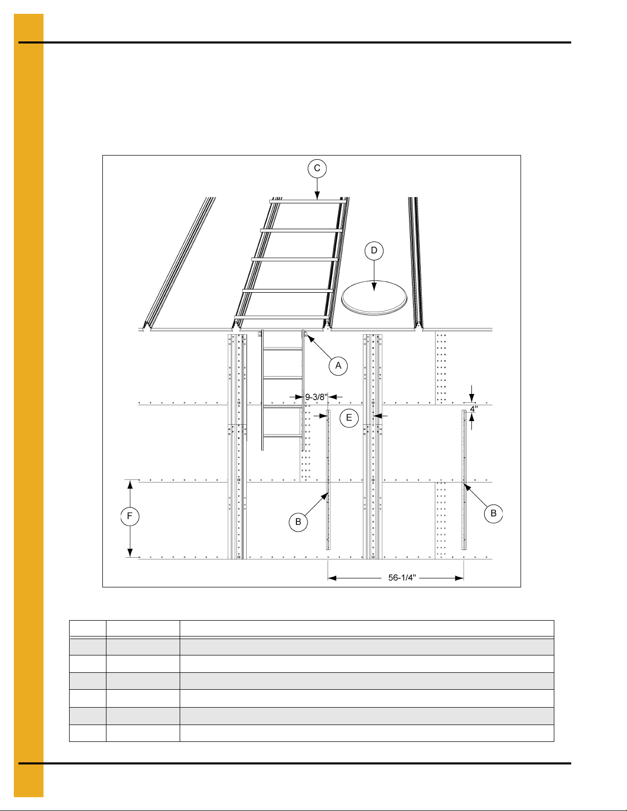
Eave Platform Mounting Angle Installation
Figure 5H shows the location of the platform mounting angles (B). Each angle must be mounted starting
4" below the top horizontal seam of the second ring with the first mounting angle offset 9-3/8" from the
right hand starter bracket (A). The second mounting angle must be located 56-1/4" from the first mounting
angle (B). The dimensions and locations of these angles are critical for proper fit of all parts. Using the
platform mounting angels (B) as guides, field drill 3/8" holes in the sidewall every 8". (See Figure 5H.)
Figure 5H
Ref # Part # Description
A LDR-4347 R.H. Starter Bracket
B TDP-5008N Fluorescent Green/Black Platform Mounting Angles (Field drill 3/8" holes on 8" centers.)
C Roof Ladder
D Manway Panel
E 18-3/4" Reference
F 32" Typical
28 PNEG-1451 Ladder, Safety Cage and Platform for Hopper Tanks
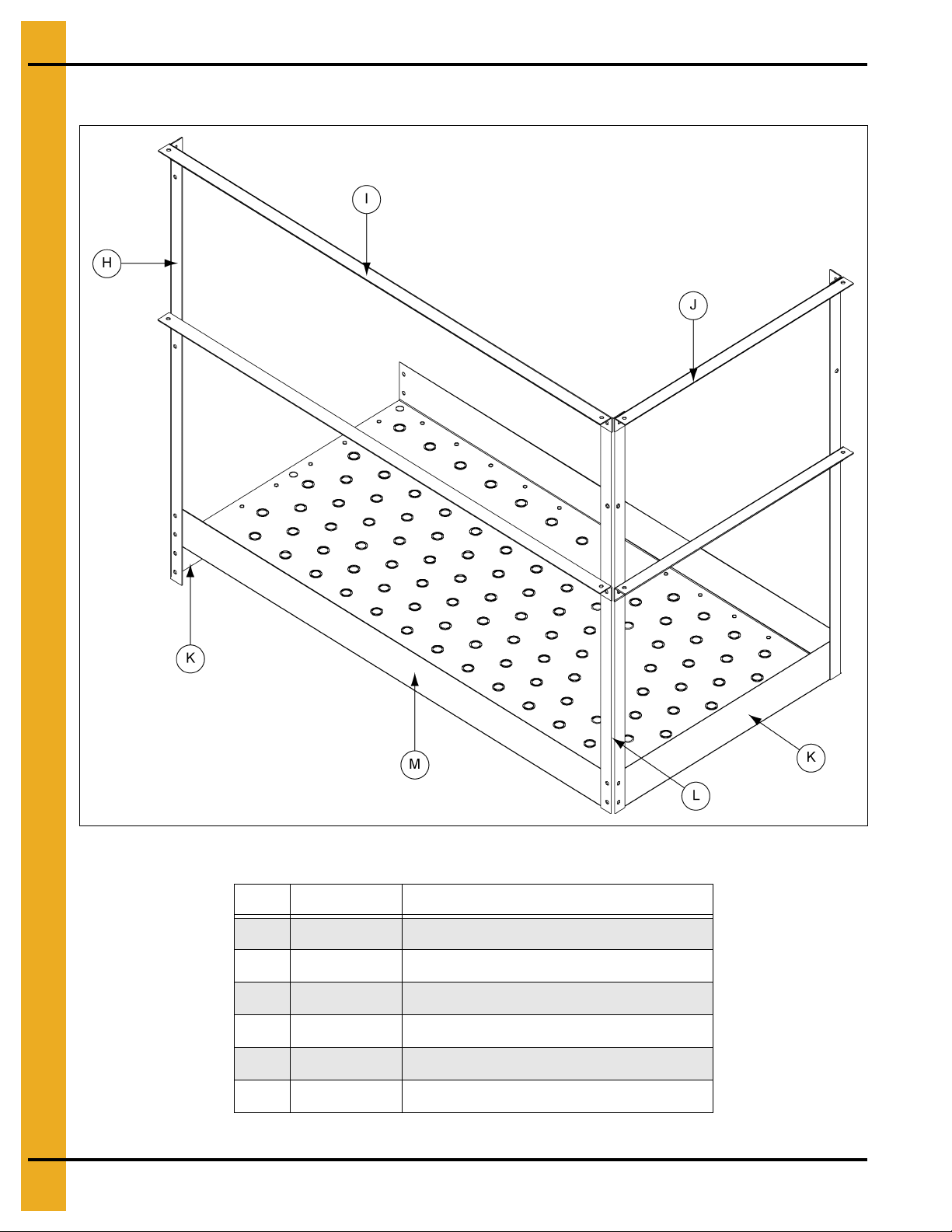
5. 2.66" Corrugated Commercial Hopper Tank 4-9 Rings
Right Hand Platform and Platform Support Assembly
NOTE: Mount the platform supports (A) on the bin first. Next, assemble the platform floor (M) onto the
support frame. Do not tighten platform support (A) to floor brace (E) bolts until the floor and
toe plates (K) are secure.
Assemble the platform support (A) frame using 5/16" x 3/4" truss head bolts and nuts. (See Figure 5I.)
When attaching the platform mounting angles (C) to the sidewall, locate the mounting angles according to
the instructions on previous pages. Align holes on the platform floor (M) with the holes on the platform
supports (A) and bolt together using 5/16" x 3/4" truss head bolts and nuts. Attach platform toe plates (K)
at the same time as attaching the platform floor (M). The vertical en trance ang le (H) bolts to the platform
floor (M), toe plate (K) and platform support (A). The handrail post (L) bolts to the platform floor (M) and
toe plate (K) as shown in Figure 5J on Page 30.
Figure 5I Right Hand Platform Support Assembly
Ref # Part # Description
A LS-6698 Platform Support (2)
B LS-6699 Left Hand Diagonal Support Angle (Brown) (1)
C TDP-5008N Platform Mounting Angle (Fluorescent Green/Black) (2)
D LS-6700 Right Hand Diago nal Support Angle (Blue) (1)
E LS-6701 Floor Brace (Orange) (3)
F Use upper hole in diagonal brace when connecting to platform support.
G Upper Hole
PNEG-1451 Ladder, Safety Cage and Platform for Hopper Tanks 29
5. 2.66" Corrugated Commercial Hopper Tank 4-9 Rings
Right Hand Platform and Platform Support Assembly (Continued)
Figure 5J Right Hand Platform
Ref # Part # Description
H LS-6621 46'' Vertical Entrance Angle (Pink) (1)
I LS-6702 58'' Handrail (Red) (2)
J TDP-5002 30'' Handrail (Pink/Black) (2)
K TDP-5011 29-3/4" Platform Toe Plate
L LS-371 42" Handrail Post (Yellow) (2)
M LS-6703 Platform Floor (1)
30 PNEG-1451 Ladder, Safety Cage and Platform for Hopper Tanks
 Loading...