

Page 1
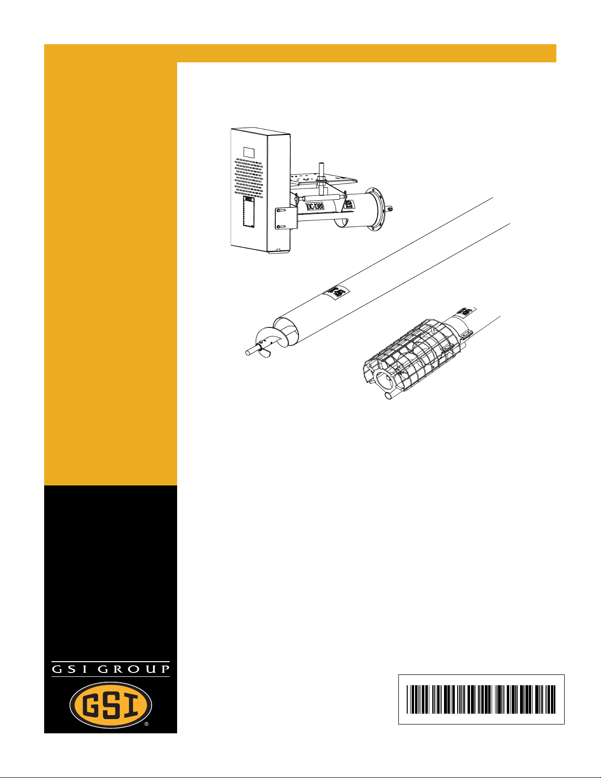
6", 8", 10", & 12" Custom Augers
Assembly & Operation Manual
PNEG-1445
Date: 05-08-07
PNEG-1445
Page 2

2 PNEG-1445 6", 8", 10", & 12" Custom Augers
Page 3

Table of Contents
Contents
Chapter 1 Introduction ....................................................................................................................... 4
General Information ............................................................................................................4
Receiving Merchandise and Filing Claims .......................................................................... 4
Capacity .............................................................................................................................. 4
Chapter 2 Safety .................................................................................................................................. 5
Safety Guidelines ................................................................................................................ 5
Safety Instructions ............................................................................................................... 6
Operator Qualifications ....................................................................................................... 9
Chapter 3 Safety Decals ................................................................................................................... 11
Chapter 4 Assembly ......................................................................................................................... 14
Motor Mount Installation Instructions for all 6", 8", 10" & 12" Custom Augers .................. 14
Assembling the Flight Extension for All 6", 8", 10" & 12" Custom Augers ......................... 22
Assembling the Intake Guard for All 6", 8", 10" & 12" Custom Augers ............................. 27
Assembling the Inlet Hopper with Bearings for All 6", 8", 10" & 12" Custom Augers ........ 29
Outlet Cutting Guidelines .................................................................................................. 32
Enclosed Slide Gates with Rack and Pinion Control ......................................................... 33
Basic Inlet Hoppers ........................................................................................................... 34
Spouting, Fittings and Truss Kits ...................................................................................... 34
Sample Custom Auger Configurations .............................................................................. 35
Chapter 5 Electric Drive Motors ...................................................................................................... 36
Power Source .................................................................................................................... 36
Chapter 6 Start-Up ............................................................................................................................ 37
Start-Up and Break-In ....................................................................................................... 37
Chapter 7 Operation/Maintenance ................................................................................................... 39
Operate the Auger ............................................................................................................. 39
Maintain the Auger ............................................................................................................ 40
Chapter 8 Shutdown ......................................................................................................................... 41
Normal Shutdown .............................................................................................................. 41
Emergency Shutdown ....................................................................................................... 41
Lockout .............................................................................................................................. 41
Storage Preparation .......................................................................................................... 41
Chapter 9 Parts List .......................................................................................................................... 43
6" Custom Auger Parts ...................................................................................................... 44
8" Custom Auger Parts ...................................................................................................... 46
8" Internal Bearing Parts ................................................................................................... 48
10" Custom Auger Parts .................................................................................................... 50
10" Internal Bearing Parts ................................................................................................. 52
12" Custom Auger Parts .................................................................................................... 54
12" Internal Bearing Parts ................................................................................................. 56
Chapter 10 Trouble Shooting ........................................................................................................... 58
Chapter 11 Warranty ......................................................................................................................... 59
PNEG-1445 6", 8", 10", & 12" Custom Augers 3
Page 4

1. INTRODUCTION
General Information
READ THIS MANUAL carefully to learn how to properly use and install equipment. Failure to do
so could result in personal injury or equipment damage.
THIS MANUAL SHOULD BE CONSIDERED a permanent part of your equipment and should be
easily accessible when needed.
WARRANTY is provided as part of the company’s support program for customers who use and
maintain their equipment as described in the manual. The warranty is explained on the warranty
page located on the inside of the back cover.
Receiving Merchandise and Filing Claims
INSPECT the shipment immediately upon arrival. The Customer is responsible for ensuring that
all quantities are correct. Report any damage or shortages by recording a detailed description
on the Bill of Lading to justify the Customer’s claim from the Transport Firm. When receiving
merchandise, it is important to check both the quantity of parts and their descriptions with the
packing list enclosed within each package. All claims for freight damage or shortage must be
made by the consignee within ten (10) days from the date of the occurrence of freight damage.
The consignee should accept the shipment after noting the damage or loss.
Capacity
1. The capacities may vary greatly under varying conditions. The following factors play a role
in the performance of the auger:
• Speed
• Angle of Operation
• Moisture Content
• Amounts of Foreign Matter
• Different Materials
• Methods of Feeding
2. For example, a twenty-five percent (25%) moisture could cut capacity by as much as 40%
under some conditions.
4 PNEG-1445 6", 8", 10", & 12" Custom Augers
Page 5
E
T
2
A
.
F
S
Y
Safety Guidelines
This manual contains information that is important for you, the owner/operator, to know and
understand. This information relates to protecting personal safety and preventing equipment
problems. It is the responsibility of the owner/operator to inform anyone operating or working in
the area of this equipment of these safety guidelines. To help you recognize this information, we
use the symbols that are defined below. Please read the manual and pay attention to these
sections. Failure to read this manual and it’s safety instructions is a misuse of the equipment and
may lead to serious injury or death.
This is the safety alert symbol. It is used to alert you
to potential personal injury hazards. Obey all safety
messages that follow this symbol to avoid possible
injury or death.
DANGER indicates an imminently hazardous situation
which, if not avoided, will result in death or serious
injury.
WARNING indicates a potentially hazardous
situation which, if not avoided, could result in death or
serious injury.
CAUTION indicates a potentially hazardous situation
which, if not avoided, may result in minor or moderate
injury.
CAUTION used without the safety alert symbol indicates
a potentially hazardous situation which, if not avoided,
may result in property damage.
NOTE indicates information about the equipment that
you should pay special attention to.
PNEG-1445 6", 8", 10", & 12" Custom Augers 5
Page 6
2. SAFETY
Safety Instructions
Our principle concern is your safety and the safety of others associated with grain handling
equipment. We want to keep you as a customer. This manual is to help you understand safe
operating procedures and some problems which may be encountered by the operator and other
personnel.
As owner and/or operator, it is your responsibility to know what requirements, hazards and
precautions exist, and to inform all personnel associated with the equipment or in the area.
Safety precautions may be required from the personnel. Avoid any alterations to the equipment.
Such alterations may produce a very dangerous situation, where SERIOUS INJURY or DEATH
may occur.
This equipment shall be installed in accordance with the current installation codes and applicable
regulations which should be carefully followed in all cases. Authorities having jurisdiction should
be consulted before installations are made.
Operate Unload Equipment Properly
Make sure ALL equipment is locked in position before
operating.
NEVER start equipment until ALL persons are clear of the work
area.
Be sure all operators are adequately rested and prepared to
perform all functions of operating this equipment.
NEVER allow any person intoxicated or under the influence of
alcohol or drugs to operate the equipment.
NEVER work alone.
Make sure someone is near by who is aware of the proper
shutdown sequence in the event of an accident or emergency.
ALWAYS think before acting. NEVER act impulsively around
the equipment.
NEVER allow anyone inside a bin, truck or wagon which is
being unloaded by an auger or conveyor. Flowing grain can trap
and suffocate in seconds.
Use ample overhead lighting after sunset to light the work area.
Keep area around intake free of obstacles such as electrical
cords, blocks, etc., that might trip workers.
Operate Unload
Equipment Safely
NEVER drive, stand or walk under the equipment.
Use caution not to hit the auger when positioning the load.
ALWAYS lockout ALL power to the equipment when finished
unloading a bin.
6 PNEG-1445 6", 8", 10", & 12" Custom Augers
Page 7

Follow Safety Instructions
Carefully read all safety messages in this manual and
on your machine safety signs. Keep signs in good
condition. Replace missing or damaged safety signs.
Be sure new equipment components and repair parts
include the current safety signs. Replacement safety
signs are available from the manufacturer.
Learn how to operate the machine and how to use
controls properly. Do not let anyone operate without
instruction.
Keep your machinery in proper working condition.
Unauthorized modifications to the machine may
impair the function and/or safety and affect machine
life.
2. SAFETY
If you do not understand any part of this manual and
need assistance, contact your dealer.
Install & Operate Electrical Equipment Properly
To avoid serious injury or death, stay away from unit
and make sure everyone is clear of all augers before
starting or operating the unit.
Electrical controls should be installed by a qualified
electrician and must meet the standards set by the
national electrical code and all local and state codes.
Disconnect and lock out all power sources before
installing wires/cables or servicing equipment.
Do not operate electric motor equipped units until
motors are properly grounded.
Disconnect power on electrical driven units before
resetting motor overloads.
Read and Understand Manual
Electric Shock Hazard
Do not repetitively stop and start the drive in order to
free a plugged condition. Jogging the drive in this type
of condition can damage the equipment.
PNEG-1445 6", 8", 10", & 12" Custom Augers 7
Page 8
2. SAFETY
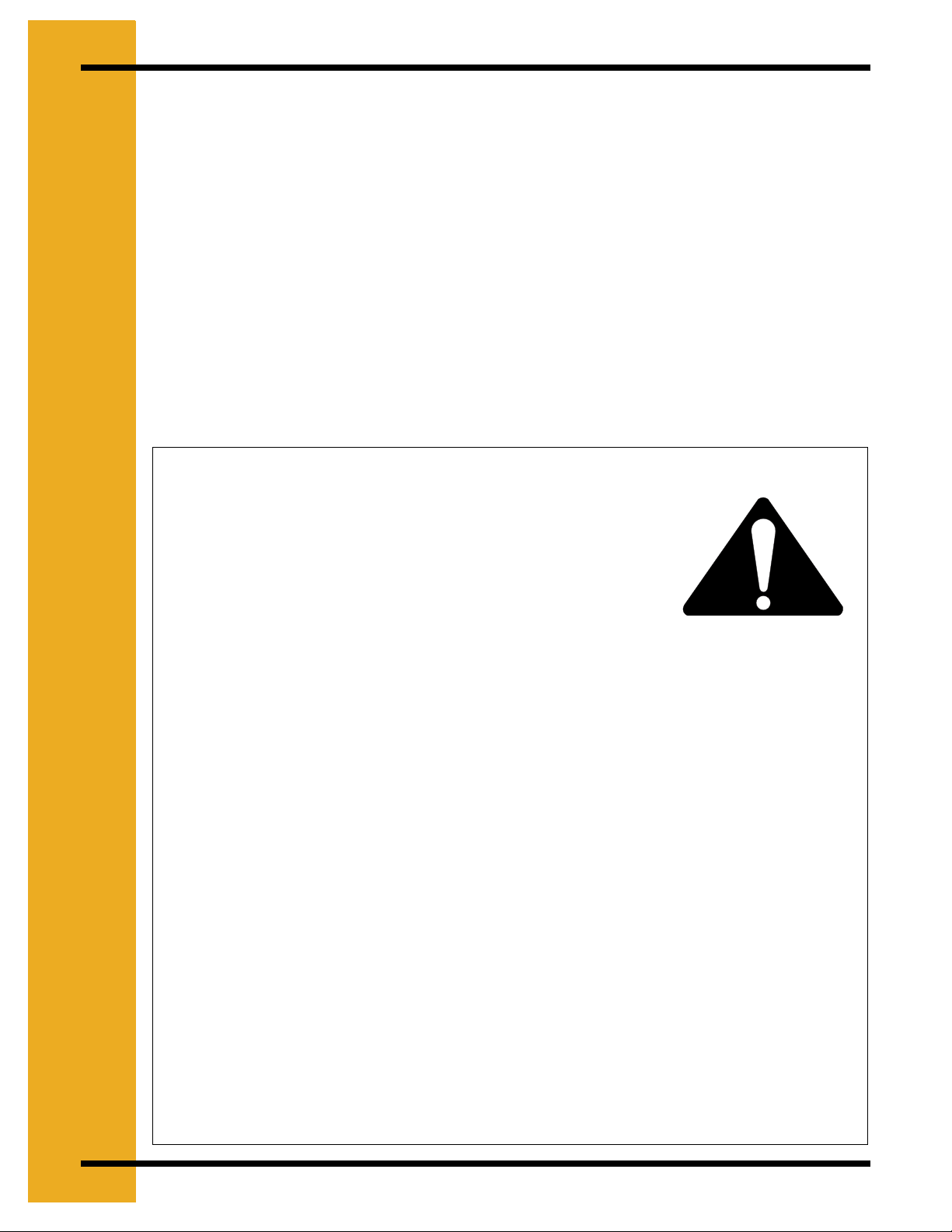
Prepare for Emergencies
Be prepared if fire starts.
Keep a first aid kit and fire extinguisher
handy.
Keep emergency numbers for doctors,
ambulance service, hospital, and fire
department near your telephone.
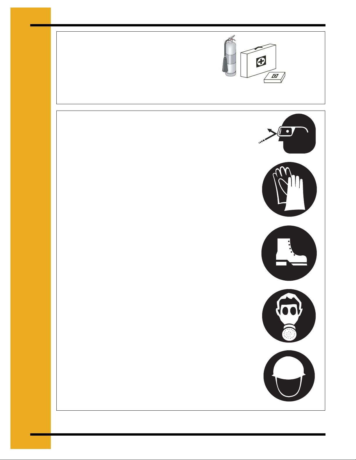
Wear Protective Clothing
Wear close fitting clothing and safety
equipment appropriate to the job.
Safety glasses should be worn at all times
to protect eyes from debris.
Keep Emergency Equipment Quickly
Accessible.
Eye Protection
Wear gloves to protect your hands from
sharp edges on plastic or steel parts.
Wear steel toe boots to help protect your
toes from falling debris.
A respirator may be needed if a hog house
has poor ventilation. Waste fumes can be
toxic.
Remove all jewelry.
Tuck in any loose or dangling shoe strings.
Long hair should be tied up and back.
Gloves
Steel Toe Boots
Respirator
Wear hard hat to help protect your head.
Hard Hat
8 PNEG-1445 6", 8", 10", & 12" Custom Augers
Page 9
2. SAFETY
Operator Qualifications
1. The User/Operator must be competent and experienced to operate auger equipment.
Anyone who works with or around augers must have good common sense in order to be
qualified. These persons must also know and meet all other qualifications, such as:
A. Any person who has not read and/or does not understand all operation and safety
instructions is not qualified to operate any auger systems.
B. Certain regulations apply to personnel operating power machinery. Personnel under
the age of 18 years may not operate power machinery, including augers. It is your
responsibility, as owner and/or supervisor, to know what these regulations are in your
area or situation.
C. Unqualified or incompetent persons are to remain out of work area.
D. O.S.H.A. (Occupational Safety & Health Administration) regulations state: “At the time
of initial assignment and at least annually thereafter, the employer shall instruct every
employee in the safe operation and servicing of all equipment with which the employee
is, or will be involved”. Federal Occupational Safety & Health Standards for Agriculture.
Sub part D, Section 19287.57 (a) (6).
2. As a requirement of O.S.H.A., it is necessary for the employer to train the employee in the
safe operating and safety procedures for this auger. We included this sign-off sheet for your
convenience and personal record keeping. All unqualified people are to stay out of the work
area at all times. It is strongly recommended that another qualified person who knows the
shutdown procedure is in the area in the event of an emergency. A person who has not read
this manual and understands all operating and safety instructions, is not qualified to operate
the machine.
Date
1
2
3
4
5
6
7
8
9
10
11
12
13
14
15
16
17
18
19
20
Employees Name (Printed) Employees Signature
PNEG-1445 6", 8", 10", & 12" Custom Augers 9
Page 10
2. SAFETY
st
SAFETY
Replace missing guards and shields
FREE OF CHARGE!
Our equipment is built to provide many years of dependable service to our customers through
durable craftsmanship.
One of the most important aspects of our engineering is SAFETY 1
product lines. Safety is NO ACCIDENT!
That is why we are implementing its SAFETY 1st program. Should you ever need guards,
shields, safety decals, or owner/operator manuals, simply contact us, and we will supply you with
them FREE OF CHARGE!
While it is our main goal to be the world leader in auger manufacturing, it is always our first
priority to keep our customers safe.
If you need any of the above listed safety items or have safety questions, please contact:
The GSI Group
PO Box 20
1004 E. Illinois Street
Assumption, IL 62510
Ph: 1-217-226-4421
st
design throughout all
10 PNEG-1445 6", 8", 10", & 12" Custom Augers
Page 11
A
L
E
E
T
Y
.
3
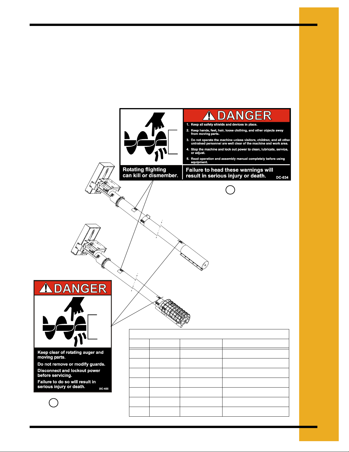
The Decal List below has all the safety decals that should be included with your equipment. The
following pages show what the decals look like and where they should be located on the
equipment. Inspect all decals and replace any that are illegible, worn, or missing. Contact your
local dealer or the manufacturer to order replacement decals free of charge.
Contact:
The GSI Group
1004 E. Illinois Street
Assumption, IL 62510
Ph: (217)-226-4421
F
S
A
C
D
S
DC-834
3
3
Bulk Auger
Utility Auger
6'', 8'', & 10'' Roof Auger Decal List
Ref # Part # Size Description
1 DC-1381 4-1/2'' x 2'' Danger - Shear Point
2 DC-994 4-1/2'' x 2'' Danger - Shear Point
3 DC-834 9'' x 3-3/4'' Danger - Unloading
4 DC-1379 5-1/8'' x 7-3/8'' Notice -1 - 11
5 DC-455 4'' x 5-3/4'' Danger - Rotating Flight
DC-455
5
PNEG-1445 6", 8", 10", & 12" Custom Augers 11
6 DC-12L34 2-1/4'' x 2-3/4'' Caution
7 DC-1395 4-1/4'' x 6-1/4'' Danger - Rotating Flight
Page 12
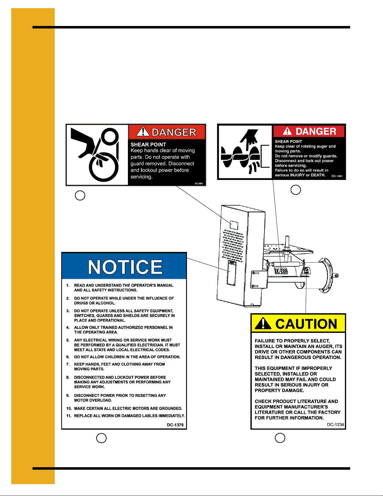
3. SAFETY DECALS
Check components shown below to insure that the safety decals are in place and in good
condition. If a decal cannot be easily read for any reason or has been painted over, replace it
immediately. Contact your dealer or the manufacturer to order a replacement Decal free of
charge.
Contact:
The GSI Group
1004 E. Illinois Street
Assumption, IL 62510
Ph: (217)-226-4421
DC-994
5
1
DC-994
DC-1381
DC-1379
4
6
DC-1234
12 PNEG-1445 6", 8", 10", & 12" Custom Augers
Page 13
3. SAFETY DECALS
Check components shown below to insure that the safety decals are in place and in good
condition. If a decal cannot be easily read for any reason or has been painted over, replace it
immediately.
Contact your dealer or the manufacturer to order a replacement Decal free of charge.
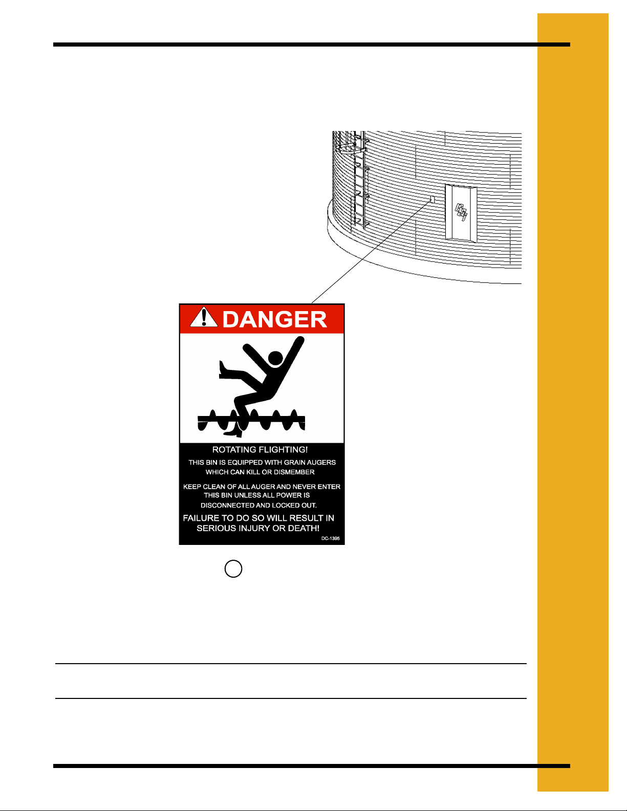
DANGER Sign No. DC-1395 was supplied with
your bin unloading equipment. This safety sign
should be applied to the side of the bin near the bin
opening, so it will be viewed by people entering into
the bin storage building. Do not cover any safety
signs or any other signs that are already there.
.
6
DC-1395
Note: Please remember, safety signs provide important safety information for people
working near bin unloading equipment that is in operation.
PNEG-1445 6", 8", 10", & 12" Custom Augers 13
Page 14
4. ASSEMBLY
Motor Mount Installation Instructions for all 6", 8", 10" & 12" Custom
Augers
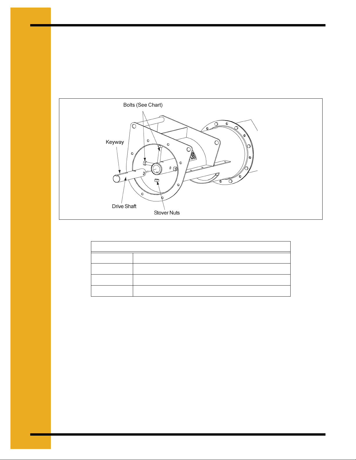
1. Installing Drive Shaft
A. Insert the Drive Shaft into the opposite end of flight with keyway facing outward.
Align the holes in the shaft and secure with Grade 8 bolts and stover nuts.
(See Chart for Bolt Sizes), (See Figure 4A).
Figure 4A
Flight Hardware
6" 3/8" - 16 x 2" Grade 8 Hex Bolts
8" 7/16" - 14 x 3" Grade 8 Hex Bolts
10" 1/2" - 13 x 3-1/2" Grade 8 Hex Bolts
12" 5/8" - 11 x 4" Grade 8 Hex Bolt
14 PNEG-1445 6", 8", 10", & 12" Custom Augers
Page 15
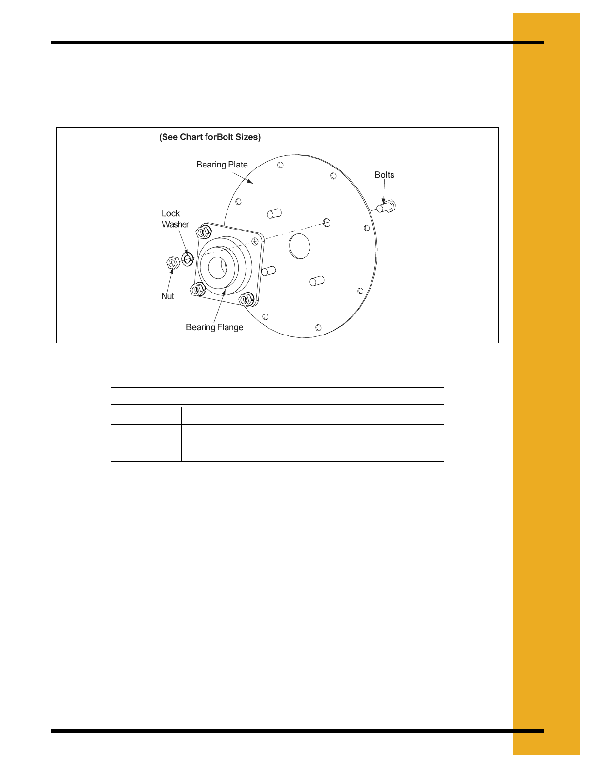
2. Mounting Bearing to Bearing Plate
A. Align bolt holes on Bearing Flange with bolt holes on Bearing Plate.
B. Secure Bearing to Bearing plate using appropriate bolts, lock washers, and nuts.
(See Chart for Bolt Sizes), (See Figure 4B).
4. ASSEMBLY
Figure 4B
Bearing Bolts
6" 7/16" - 14 x 1-1/2" Bolt
8" & 10" 1/2" - 13 x 1-1/2" Bolt
12" 5/8" - 11 x 2" Bolt
PNEG-1445 6", 8", 10", & 12" Custom Augers 15
Page 16
4. ASSEMBLY
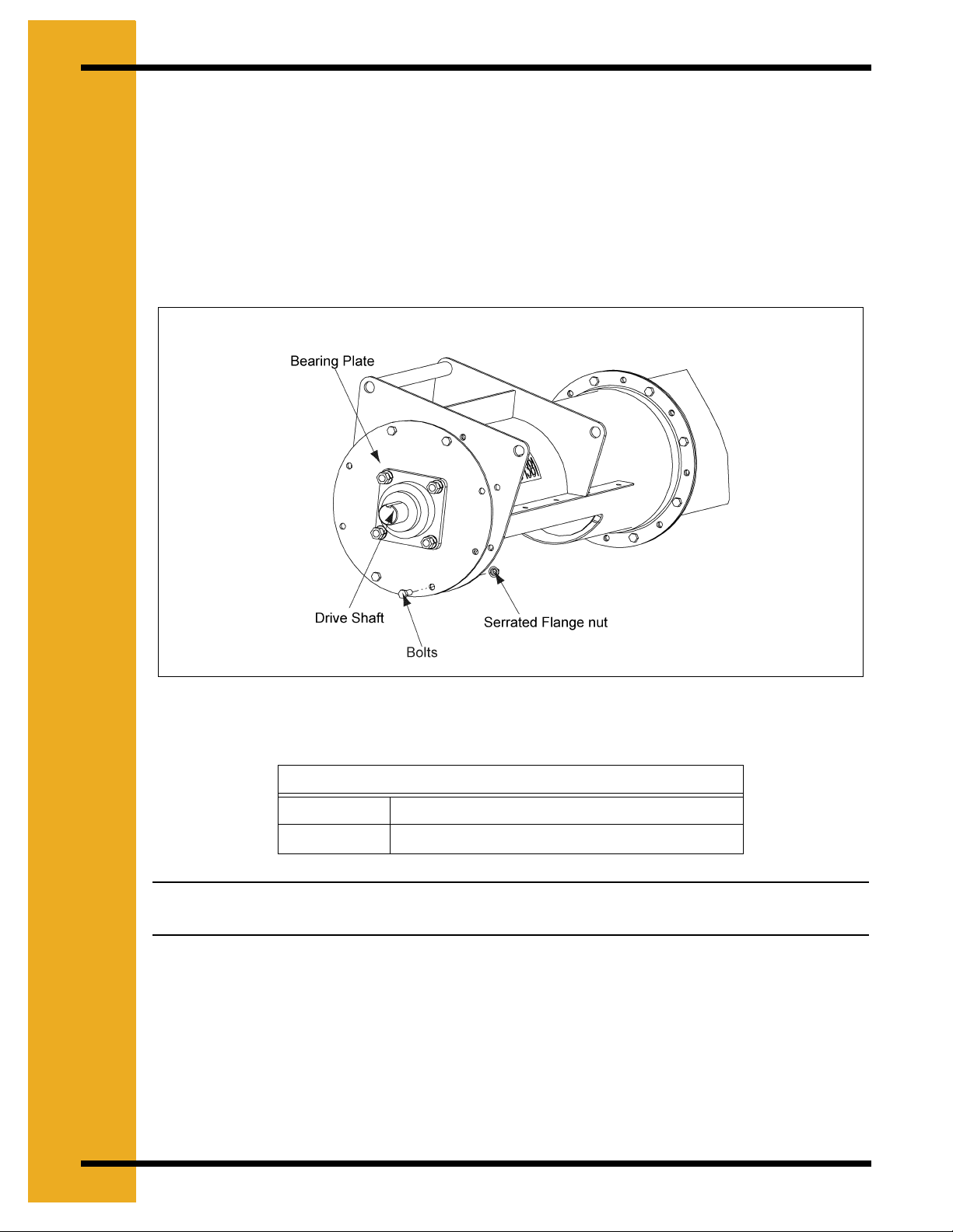
3. Installing Bearing Plate onto Tube
A. Align Bearing with Drive Shaft and slip Shaft through bearing.
B. Rotate Plate until bolt holes in tube flange and plate align. Secure with appropriate
bolts, and Serrated Flange nut (See Chart for Bolt Sizes).
C. Only Secure with UPPER and LOWER four (4) bolts (See Figure 4G). The other
four (4) bolts will be installed later with the Belt Guard Mounting Brackets.
(See Chart for Bolt Sizes).
(See Chart for Bolt Sizes)
Figure 4C
Bearing Plate Bolts
6" & 8" 5/16" - 18 x 1" Bolt
10" & 12" 3/8" - 16 x 1" Bolt
Note: On the 10" & 12" systems use the four (4) 3/8" x 1" –16 bolts in this step, the longer
bolts will be used to attach the Belt Guard Mounting Brackets in a future step.
4. Installing the Motor Mount Adjuster
A. Place Motor Mount Adjuster between the Back Plate and Head Plate on the
Discharge Tube.
B. Insert Pivot Rod through the Tube plates and Motor Mount Adjuster. Secure in place
with two (2) 3/16" x 2" cotter pins. (See Figure 4D).
16 PNEG-1445 6", 8", 10", & 12" Custom Augers
Page 17
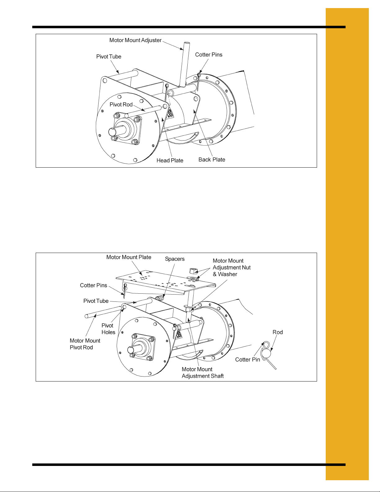
5. Installing the Motor Mount Plate
4. ASSEMBLY
Figure 4D
A. Secure one (1) of the motor mount adjustment nuts and one (1) the motor mount
adjustment washers approximately 3/4 of the way down the motor mount adjuster’s
threaded shaft.
B. Once the nut and washer is secure, slip the Motor Mount Plate over the adjuster and
align the pivot holes with the pivot tube. (See Figure 4E).
Figure 4E
C. Slide the Motor Mount Pivot Rod through the pivot tube on the Discharge Tube.
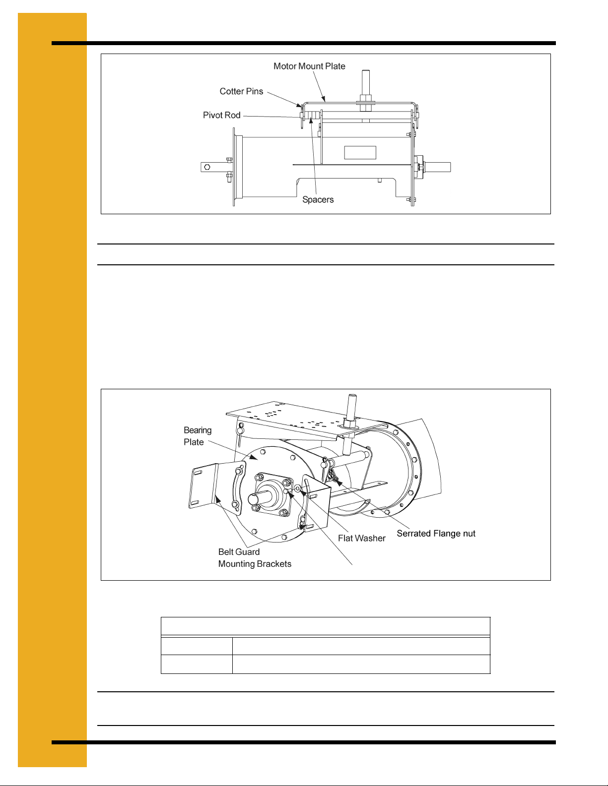
D. When the pivot rod begins to extend through the pivot tube install the spacers,
BETWEEN the Back Plate and the inner face of the Motor Mount Plate.
(See Figure 4F).
PNEG-1445 6", 8", 10", & 12" Custom Augers 17
Page 18
4. ASSEMBLY
Figure 4F
Note: The number of spacers will vary between each size of unloader.
6. Installing the Belt Guard Brackets
A. Align the holes on the Bearing Plate with the slots on the Belt Guard Mounting
Brackets.
B. Secure the Brackets with proper bolts, flat washers, and Serrated Flange nut .
(See Chart for Bolt Sizes), (See Figure 4G).
(See Chart for Bolt
Figure 4G
Belt Guard Bracket Bolts
6" & 8" 5/16" - 18 x 1" Bolt
10" & 12" 3/8" - 16 x 1-1/4" Bolt
Note: DO NOT tighten the bolts completely. The brackets will need to be rotated to align
the slot in the Belt Guard with the shafts on the motor and flight.
18 PNEG-1445 6", 8", 10", & 12" Custom Augers
Page 19

7. Installing the Lock Collar
A. Slide the Lock Collar over the Drive Shaft, positioning it against the bearing. Do not
tighten the lock collar at this time as it will be tightened later in the assembly.
(See Figure 4H).
4. ASSEMBLY
8. Installing the Pulley
A. Place and position the key into the keyway located on the Drive Shaft.
B. Place the pulley onto the Drive Shaft with the setscrew side of the pulley facing
away from the Bearing Plate. Position the pulley so that it is as close to the lock
collar as possible, but not touching it.
C. Once the pulley is appropriately positioned, tighten the setscrew with a hex head
wrench to secure it to the drive shaft. (See Figure 4I).
Figure 4H
Figure 4I
PNEG-1445 6", 8", 10", & 12" Custom Augers 19
Page 20

4. ASSEMBLY
9. Tightening the Lock Collar
A. Using a punch and hammer, drive the lock collar clockwise (the same direction as
the shaft rotation). Once the lock collar is set in place, use a hex head wrench to
tighten the lock collar by tightening the setscrew.
Note: If the lock collar is not turned far enough, the setscrew will not lock it into place.
10. Installing the Motor (Not Provided)
A. Attach the Motor to the Motor Mount Plate using appropriate bolts, lock washers,
and hex nuts. (See Chart for Bolt Sizes).
B. Install pulley onto motor shaft making sure that it is aligned with the flight pulley. It
may be necessary to move spacers to gain shaft alignment. (See Figure 4J).
Figure 4J
Motor Bolt Chart
Motor Size Hex Bolt Size Qty
56 5/16" -18 x 1-1/4" 4
143T
145T
182T 3/8" - 16 x 1-1/4" 4
184T
213T
215T
254T 1/2" -13 x 1-3/4" 4
256T
20 PNEG-1445 6", 8", 10", & 12" Custom Augers
Page 21

11. Installing the Belts
A. Place the belts onto the pulleys.
B. First screw the lower Motor Mount Adjustment Nut upward, raising the Motor Mount
Plate, putting tension on the belts.
C. Once the desired tension is reached tighten the Upper Motor Mount Adjustment Nut
down onto the Motor Mount Plate locking it into place.
12. Installing the Belt Guard
A. With the belts properly tensioned remove the bottom Belt Guard cover and slip Belt
Guard down over motor shaft.
B. Bolt the Belt Guard to the Belt Guard Mounting Brackets, the brackets should still
be loose at this time.
C. Align the motor shaft and the Flight Drive Shaft in the Belt Guard’s slot, making sure
that the Belt Guard DOES NOT contact either pulley, and tighten down the Belt
Guard Mounting Brackets to the Bearing Plate. (See Figure 4K).
4. ASSEMBLY
D. Once the brackets are tightened slide the bottom cover back into place and secure
with supplied bolt.
Figure 4K
PNEG-1445 6", 8", 10", & 12" Custom Augers 21
Page 22

4. ASSEMBLY
Assembling the Flight Extension for All 6", 8", 10" & 12" Custom
Augers
13. Standard Assembly without Bearings
Note: If your auger does not include an extension skip ahead to Step - 13E.
A. Begin by sliding the extension connecting band onto the main auger tube.
(See Figure 4L).
Figure 4L
22 PNEG-1445 6", 8", 10", & 12" Custom Augers
Page 23

4. ASSEMBLY
B. Slide the flight connecting shaft into the main section of flight and bolt together with
Grade 8 Hex Bolt and Stover nut. Next slide extension flight onto connecting shaft
and bolt together using proper grade 8 bolts and stover nuts. (See Chart for Bolt
Sizes), (See Figure 4M).
Figure 4M
Flight Hardware
6" 3/8" - 16 x 2" Grade 8 Hex Bolts
8" 7/16" - 14 x 3" Grade 8 Hex Bolts
10" 1/2" - 13 x 3-1/2" Grade 8 Hex Bolts
12" 5/8" - 11 x 4" Grade 8 Hex Bolt
C. Slide the extension tube over the extension flight, making sure the tube is pressed
securely against the main auger tube. (See Figure 4N).
Figure 4N
PNEG-1445 6", 8", 10", & 12" Custom Augers 23
Page 24

4. ASSEMBLY
D. Slide the extension connecting band over the two sections of tube, making sure the
connecting band is centered over the mated surfaces of the tubes. Tighten the
connecting band down using the correct Hex Bolts and Nylock nuts.
(See Chart for Bolt Sizes), (See Figure 4O).
Figure 4O
Connecting Band Bolts
6" & 8" 5/16" -18 x 1" Hex Bolt
10" & 12" 3/8" - 16 x 1" Hex Bolt
E. Insert the intake shaft into the flight and connect with proper grade 8 bolt and stover
nut. (See Chart for Bolt Sizes), (See Figure 4P).
Figure 4P
Flight Hardware
6" 3/8" - 16 x 2" Grade 8 Hex Bolts
8" 7/16" - 14 x 3" Grade 8 Hex Bolts
10" 1/2" - 13 x 3-1/2" Grade 8 Hex Bolts
12" 5/8" - 11 x 4" Grade 8 Hex Bolt
24 PNEG-1445 6", 8", 10", & 12" Custom Augers
Page 25

14. Assemblies with Internal Bearings
A. Slide Connecting Band onto main auger tube, and attach Connecting Stub to main
auger flight using the assigned hardware. (See Chart for Bolt Sizes), (See Figure
4Q).
4. ASSEMBLY
Figure 4Q
Flight Hardware
6" 3/8" - 16 x 2" Grade 8 Hex Bolts
8" 7/16" - 14 x 3" Grade 8 Hex Bolts
10" 1/2" - 13 x 3-1/2" Grade 8 Hex Bolts
12" 5/8" - 11 x 4" Grade 8 Hex Bolt
B. Slide Hanger Bearing onto Connecting Stub, followed by Extension Flight. Bolt
Extension Flight to Connecting Stub using assigned hardware.
(See Chart Above), (See Figure 4R).
Figure 4R
PNEG-1445 6", 8", 10", & 12" Custom Augers 25
Page 26

4. ASSEMBLY
C. With flight sections bolted together slide Extension Tube flush against Main Auger
Tube. (See Figure 4S).
D. With tube sections pressed flush against each other slide Connecting Band over the
tubes aligning the holes. Reach through the Access Hole and align Hanger Bearing
with the bolt hole. Attach the Hanger Bearing to the tube using assigned hardware.
(See Chart for Bolt Sizes), (See Figure 4T).
Figure 4S
Figure 4T
Hanger Bearing Bolt
8" 5/8" -11 x 1-3/4" Grade 8 Bolt
10" 5/8" -11 x 1-3/4" Grade 8 Bolt
12" 3/4" -10 x 2" Grade 8 Bolt
26 PNEG-1445 6", 8", 10", & 12" Custom Augers
Page 27

4. ASSEMBLY
E. With Hanger Bearing secured bolt connecting band to tubes using the
3/8" -16 x 1-1/2" Hex Bolts and attach Access Cover using included Nylock Nuts.
(See Figure 4U).
Figure 4U
Assembling the Intake Guard for All 6", 8", 10" & 12" Custom Augers
15. Installing the Intake Guard
Note: For Utility Augers Only.
A. Slide the Intake guard onto the Auger Tube aligning the intake shaft with the bronze
bushing. (See Figure 4V).
Figure 4V
PNEG-1445 6", 8", 10", & 12" Custom Augers 27
Page 28

4. ASSEMBLY
B. With the Intake Shaft inserted in the bushing make sure to leave approximately
1/2" of clearance between the end of the Flight and the face of the bushing.
(See Figure 4W).
Figure 4W
C. Attach the Intake Guard to the Tube using the proper hex bolts and Nylock nuts
through the half bands that are welded to the Intake Guard.
(See Chart for Bolt Sizes), (See Figure 4X).
Figure 4X
Intake Guard Bolts
6" 5/16" - 18 x 1-3/4" GR5 Hex Bolt
8" 5/16" - 18 x 1-3/4" GR5 Hex Bolt
10" 3/8" - 16 x 1-1/2" GR5 Hex Bolt
28 PNEG-1445 6", 8", 10", & 12" Custom Augers
Page 29

4. ASSEMBLY
D. Place Intake Guard Half Band above the lower half band on the Intake Guard and
attach using proper hex bolts and Nylock nuts. (See Chart Above), (See Figure 4Y).
Figure 4Y
Assembling the Inlet Hopper with Bearings for All 6", 8", 10" & 12"
Custom Augers
16. Installing Intake Shaft
A. Begin by assembling the intake shaft to the flight using the required Grade 8 bolts
and stover nuts. (See Chart for Bolt Sizes), (See Figure 4Z).
Figure 4Z .
Flight Hardware
6" 3/8" - 16 x 2" Grade 8 Hex Bolts
8" 7/16" - 14 x 3" Grade 8 Hex Bolts
10" 1/2" - 13 x 3-1/2" Grade 8 Hex Bolts
PNEG-1445 6", 8", 10", & 12" Custom Augers 29
Page 30

4. ASSEMBLY
B. Next bolt the bearing with flangette to the studs on the hopper using the required
lock washer and nut. (See Chart for Bolt Sizes), (See Figure 4AA).
Figure 4AA
Hopper Bearing Nut
6" 5/16" - 18 Hex Nut
8" 3/8" - 16 Hex Nut
10" 1/2" - 13 Hex Nut
30 PNEG-1445 6", 8", 10", & 12" Custom Augers
Page 31

17. Attach Hopper
A. Slide the hopper onto the tube and align the end of the flight approximately 1/2" from
the surface of the bearing. With the proper distance set, install the proper bolt, lock
washer and nut, and secure the hopper to the tube.
(See Chart for Bolt Sizes), (See Figure 4AB).
4. ASSEMBLY
Figure 4AB
Hopper Connecting Band Bolt
6" & 8" 5/16" - 18 x 1" Hex Bolt
10" 5/16" - 18 x 1-1/2" Hex Bolt
PNEG-1445 6", 8", 10", & 12" Custom Augers 31
Page 32

4. ASSEMBLY
Outlet Cutting Guidelines
1. Before ordering, predetermine the location of the outlet drops. Make sure the outlet drops
do not interfere with the connecting band locations.
2. When an outlet opening is cut, that section of tube loses much of it’s strength therefore
additional support may be necessary.
3. If you have internal bearing flighting, outlets may be cut below internal bearings but a hole
must cut in the spout halfband allow access to internal hanger bearing.
4. We recommend removing flight before cutting the tube otherwise flight will be notched and/
or rough edges will occur. This may not significantly impact the performance of the auger,
but burrs and metal chips should be removed or abnormal wear will result. Also, grind down
any rough edges on tubing for a better fit and smoother operation.
5. Carefully measure your outlet before cutting. Follow the recommended guidelines as shown
below. It is very important that the opening be large enough not to reduce capacity, but
small enough so the outlet can be covered securely by the spout.
Figure 4AC
32 PNEG-1445 6", 8", 10", & 12" Custom Augers
Page 33

4. ASSEMBLY
Enclosed Slide Gates with Rack and Pinion Control
1. Follow cutting guidelines on Page - 34.
2. Attach spout to tube with backband.
3. Remove smaller outside nut from the rack and pinion connecting rod and insert rod through
the hole in the angle on the slide gate and secure with the smaller outside nut.
4. Fully close slide gate. Using the pulley, adjust the halfbands so they are located at the end
of the control rod farthest from the spout. Then tighten the halfbands to the tube.
5. Wrap rope or cable around the pulley, doubling it to prevent slippage.
Figure 4AD
PNEG-1445 6", 8", 10", & 12" Custom Augers 33
Page 34

4. ASSEMBLY
Basic Inlet Hoppers
1. Follow the cutting guidelines on on Page - 34.
2. Attach hoppers to tube as shown below.
3. Follow the instructions below before cutting and installing inlet hopper.
a. Slide ring flange onto the end of tube and weld, making sure the flange is mounted
squarely.
b. Bolt end plate to flange.
c. Bolt bearing to end plate.
d. Guide intake stub through bearing and tighten the lock collar.
e. Install any covers if applicable.
Figure 4AE
Spouting, Fittings and Truss Kits
Spouting and Fittings
To connect sections of spouting or to connect fittings to spouting, use one or all of the following
procedures:
1. Spouting to Spouting
place. Make sure flanges are mounted squarely. Join flanges and bolt together.
2. Spouting to Fitting
(valve, dead head, slip joints, etc.,).
3. Flange Clamps
4. Quick-Connect Flange Clamps
location where permanent unions are required.
34 PNEG-1445 6", 8", 10", & 12" Custom Augers
- Slide flange rings over ends of spouting to be joined and weld in
- Install ring flange on spouting as in Step 1. Join to flange on fitting
- Fit each half over flanges and tighten with bolts provided.
- Fit each half over flange and tighten bolt. Do not use in
Page 35

4. ASSEMBLY
Truss Kits
Truss rod kits are designed to provide support for support for spouting and certain auger
sections. There are two different kits available for trussing. 20' to 30' Span Kits and 30' to 40'
Span kits for spouting only. See the Instructions that are included with your kit for proper
installation.
Sample Custom Auger Configurations
Figure 4AF
PNEG-1445 6", 8", 10", & 12" Custom Augers 35
Page 36

5. ELECTRIC DRIVE MOTORS
Power Source
1. Use electric motors that operate at 1750 R.P.M
2. Electric motors and controls should be installed by a qualified electrician and must meet the
standards set by the National Electrical Code and all local and state codes.
3. A magnetic starter should be used to protect your motor when starting and stopping. It
should stop the motor in case of power interruption, conductor fault, low voltage, circuit
interruption, or motor overload. Then the motor must be restarted manually. Some motors
have built-in thermal overload protection. If this type motor is used, use only those with a
manual reset.
WARNING
A main power disconnect switch capable of being locked only in the OFF position shall
be provided. This shall be locked whenever work is being done on the auger.
CAUTION
Disconnect power before resetting motor overloads.
WARNING
Make sure all electrical motors are grounded.
WARNING
Reset and motor starting and stopping controls must be located so that the operator has
full view of the entire operation.
DANGER
Shut off power to adjust, service, or clean the machinery.
DANGER
Keep all safety guards and shields in place.
36 PNEG-1445 6", 8", 10", & 12" Custom Augers
Page 37

-
6
A
.
T
S
R
T
U
Start-Up and Break-In
DANGER
ALWAYS keep ALL guards and shields in place, until all the power is disconnected and
locked out.
1. Make sure all belts are tensioned properly.
2. Make sure ALL shields are in place and that the belt(s) and pulley(s) are able to move
freely.
3. Double check the assembly instructions to see that all parts have been assembled properly.
4. During operation of equipment, one person should be in a position to monitor the entire
operation.
Note: During the initial start-up and break-in period, the operator should note any
unusual vibrations or noises and take the appropriate action.
P
WARNING
Make certain everyone is clear before operating or moving the machine.
5. The bin well inside the bin should have a control gate. The gate should be closed before
start-up and closed before shutdown to allow the machine to clean out.
6. The controls for the control gate should either pull or push open, depending on the type of
well you have. Use the control gate to regulate a flow of less than full capacity until several
hundred bushels of grain have been augered to polish the flighting assembly and tube.
7. Any new screw conveyor or one that has set idle for a season should go through a
“break-in" period. This “break-in" consists of running the auger at half capacity until the
screw becomes polished and smooth before attempting to run at full capacity. It is
recommended that several hundred bushels of grain be augered at partial capacity.
CAUTION
Failure of your auger is very likely to occur if it is run at full capacity before the screw has
become polished.
PNEG-1445 6", 8", 10", & 12" Custom Augers 37
Page 38

6. START-UP
CAUTION
NEVER operate augers empty for any length of time as excessive wear will result.
8. Do not stop or start augers under load, especially before the flight and tube become well
polished, as this may cause the auger to “lockup”.
CAUTION
Excessive wear will result if auger is run at speeds in excess of what is recommended.
9. Do not run auger at to slow speed, this will load up or over load the auger. An loading up of
the auger will cause the motor to over load and a higher torque will be required to turn the
auger, which in turn may cause damage to the auger.
38 PNEG-1445 6", 8", 10", & 12" Custom Augers
Page 39

N
C
N
E
A
/
M
I
A
O
E
P
R
.
O
7
Operate the Auger
Note: The auger capacity can fluctuate greatly under varying conditions. Moisture
content, different commodities, amount of foreign matter and speeds all play a part
in the performance of the auger. Twenty-five percent(25%) moisture may cut
capacity by as much as 40% under some conditions.
1. Make certain there are at least two (2) people in the work area to monitor operations at all
times.
2. Visually inspect the auger periodically during operation.
N
T
I
N
T
A
E
WARNING
Be alert for any unusual vibrations, noises and the loosening of any fasteners. If anything
unusual is detected, immediately shutdown the auger, disconnect and lockout the power
source before servicing.
3. Consideration should be given to the proper size auger for a batch drying or any intermittent
type operations. When augers are stopped and restarted under full load, it may result in
damage to the auger. Using a larger diameter auger and reducing its load level will be far
better than subjecting a smaller diameter auger to big loads. If an auger is kept from
absolute filling, it will make startup easier and will convey more efficiently.
PNEG-1445 6", 8", 10", & 12" Custom Augers 39
Page 40

7. OPERATION/MAINTENANCE
Maintain the Auger
DANGER
ALWAYS shutdown and disconnect the power supply before adjusting, servicing or cleaning the
equipment.
1. Use caution when repairing or replacing equipment parts.
2. Make sure ALL decals are legible and tightly attached to the auger. If necessary, replace
them FREE OF CHARGE by contacting your dealer or the manufacturer.
3. Ensure that ALL electric motors, etc. are operating at the proper speed.
4. Maintain proper adjustments on the belt(s).
5. Mount controls for any electric motors at a safe distance from the machine and in a location
accessible in case of an emergency.
6. Make sure ALL electrical wiring is not damaged, and that it meets proper wiring codes.
7. Make sure ALL components are in good working condition before use.
8. Check the auger flighting to make sure it is in good working condition.
9. Check the internal bearing bracket, bearing and universal joint to make sure they are in
good working order.
10. Grease bearing at least two (2) times each season.
40 PNEG-1445 6", 8", 10", & 12" Custom Augers
Page 41

N
W
D
T
8
H
.
U
S
O
Normal Shutdown
1. Make certain unloading tubes are empty before stopping the unit.
2. Disconnect and lockout the power source before leaving the work area.
Emergency Shutdown
1. Know how to shutdown the auger in case of an emergency.
2. Disconnect and lockout the power source.
3. Close bin well control gates.
4. Clear out as much grain from the auger and hopper as you can.
CAUTION
Never restart when under a full load. Starting unit under load may result in damage to the
machine. Such damage is considered abuse of the equipment.
5. Reconnect and unlock the power source.
6. Gradually clear the auger until there is no grain or obstructions.
Lockout
1. Always stop and disconnect the power source whenever the operator must leave the work
area or for maintenance of the machinery.
2. Make sure equipment is locked out and that the machinery cannot be started while the
operator is not in the work area.
WARNING
Use the type of main power disconnect switch that is capable of being locked only in the
off position.
Storage Preparation
1. Close all wells to discharge auger tube.
2. Be sure the unload tube is empty.
3. Make sure power source is disconnected and locked out.
4. Check to see that all fasteners are secure.
PNEG-1445 6", 8", 10", & 12" Custom Augers 41
Page 42

NOTES
42 PNEG-1445 6", 8", 10", & 12" Custom Augers
Page 43

1. 6" Custom Auger Parts
2. 8" Custom Auger Parts
3. 8" Internal Bearing Parts
4. 10" Custom Auger Parts
5. 10" Internal Bearing Parts
6. 12" Custom Auger Parts
7. 12" Internal Bearing Parts
9
L
I
S
S
T
A
.
R
P
T
PNEG-1445 6", 8", 10", & 12" Custom Augers 43
Page 44

9. PARTS LIST
6" Custom Auger Parts
44 PNEG-1445 6", 8", 10", & 12" Custom Augers
Page 45

6" Custom Auger Parts
Ref # Part # Description
1 GK7005 Belt Guard Assembly
S-1323 B48 V-Belt (12'' Sheaves)
2
GK2349 B54 V-Belt (15'' Sheaves)
3 GK-7062 Belt Guard Mounting Bracket
4 S-9065 3/8" - 16 x 1" Flange Bolt
5 S-1196 5/16" - 18 x 1" Bolt
6 S-845 5/16" Flat Washer
7 GK-6996 Horizontal Power Head Tube
8 S-3611 5/16" - 18 Serrated Flange Nut
9 S-275 5/16" - 18 x 3/4" Bolt
10 S-3611 5/16" - 18 Serrated Flange Nut
11 S-234 3/4" - 10 Hex Nut
12 S-866 3/4" Flat Washer
13 GK-7060 Motor Mount Adjuster
14 GK6994 3*16" x 2" Cotter Pin
15 S-7052 Motor Plate
16 S-1117 1" x 7" Intake Shaft
17 S-7058 Motor Mount Pivot Rod
18 S-7837 7/16" - 14 x 1-1/2" Bolt
19 GK7061 Bearing Plate
20 S-1196 5/16" - 18 x 1" Bolt
21 GK1049 1" ID w/ 2 Hole Flangette Bearing
22 S-7014 7/16" Lock Washer
23 S-7332 7/16" - 14 Nut
GK1309 12" x 1.0" 1 Belt Sheave
GK1321 12" x 1.0" 2 Belt Sheave
24
GK2544 15" x 1.0" 2 Belt Sheave
GK4643 12" x 1.0" 3 Belt Sheave
GK2545 15" x 1.0" 3 Belt Sheave
25 S-3727 3/18" - 16 x 1-3/4" Grade 8 Bolt
26 GK2025 1" x 10" Drive Shaft
27 S-4513 1/4" x 1/4" x 2" Square Key
28 S-8251 3/8" - 16 Stover Nut
GK2854 6" x 11' Discharge Flight
29
GK2855 6" x 16' Discharge Flight
GK-2856 6" x 21' Discharge Flight
30 GK-7082 6" x 9' Tube
GK7083 6" x 14' Tube
30
GK7084 6" x 19' Tube
9. PARTS LIST
PNEG-1445 6", 8", 10", & 12" Custom Augers 45
Page 46

9. PARTS LIST
8" Custom Auger Parts
46 PNEG-1445 6", 8", 10", & 12" Custom Augers
Page 47

8" Custom Auger Parts
Ref # Part # Description
Belt Guard Assembly
1
GK7005 12" & 15" Sheaves
GK7068 18.4" Sheaves
GK1952 B50 V-Belt (12" Sheaves)
2
GK-1346 B57 V-Belt (15" Sheaves)
MHC00160 B64 V-Belt (18.4" Sheaves)
Belt Guard Mounting Bracket
3
GK7006 12" & 15" Sheaves
GK7100 18.4" Sheaves
4 S-9065 3/8" - 16 x 1" Flange Bolt
5 S-1196 5/16" - 18 x 1" Bolt
6 S-845 5/16" Flat Washer
7 GK6997 Horizontal Power Head Tube
8 S-2611 5/16" - 18 Serrated Flange Nut
9 S-275 5/16" - 18 x 3/4" Bolt
10 S-3611 5/16" - 18 Serrated Flange Nut
11 S-240 1" - 8 Hex Nut
12 S-7835 1" Flat Washer
13 GK7060 Motor Mount Adjuster
14 GK7012 Motor Mount Adjustment Rod
15 S-6994 3*16" x 2" Cotter Pin
16 GK6986 Motor Plate
17 GK7014 Pivot Tube Spacer
18 GK7013 Motor Mount Pivot Rod
19 S-8760 1/2" - 13 x 1-1/2" Bolt
20 GK6987 Bearing Plate
21 S-1196 5/16" - 18 x 1" Bolt
22 GK1330 1-1/4" ID w/ 2 Hole Flangette Bearing
23 S-236 1/2" Lock Washer
24 S-7510 1/2" - 13 Nut
GK1335 12" x 1.25" 2 Belt Sheave
GK1869 15" x 1.25" 2 Belt Sheave
GK2567 18.4" x 1.25" 2 Belt Sheave
25
GK2234 15" x 1.25" 3 Belt Sheave
GK2570 18.4" x 1.25" 3 Belt Sheave
26 GCO7674 1-1/4" Bushing for 18.4" Sheaves
27 S-8316 7/16" - 14 x 3" Grade 8 Bolt
28 GK1331 1-1/4" x 10" Drive Shaft
29 S-4513 1/4" x 1/4" x 2" Square Key
30 S-8317 7/16" - 14 Stover Nut
GK2879 8" x 11' Discharge Flight
31
GK2880 8" x 16' Discharge Flight
GK2881 8" x 21' Discharge Flight
32 GK1884 1-1/4" x 9" Intake Shaft
GK7079 8" x 8' Tube
33
GK7080 8" x 13' Tube
GK7081 8" x 18' Tube
9. PARTS LIST
PNEG-1445 6", 8", 10", & 12" Custom Augers 47
Page 48

9. PARTS LIST
8" Internal Bearing Parts
48 PNEG-1445 6", 8", 10", & 12" Custom Augers
Page 49

8" Internal Rearing Parts
Ref # Part # Description
Belt Guard Top Assembly
1
GK7005 12" & 15" Sheaves
GK7068 18.4" Sheaves
GK1952 B50 V-Belt (12" Sheaves)
2
GK1346 B57 V-Belt (15" Sheaves)
MHC00160 B64 V-Belt (18.4" Sheaves)
3
GK7006 12" & 15" Sheaves
3 GK7100 18.4" Sheaves
4 S-9065 3/8" - 16 x 1" Flange Bolt
5 S-1196 5/16" - 18 x 1" Bolt
6 S-845 5/16" Flat Washer
7 GK6997 Horizontal Power Head Tube
8 S-3611 5/16" - 18 Serrated Flange Nut
9 S-275 5/16" - 18 x 3/4" Bolt
10 S-3611 5/16" - 18 Serrated Flange Nut
11 S-240 1" - 8 Hex Nut
12 S-7835 1" Flat Washer
13 GK7060 Motor Mount Adjuster
14 GK7012 Motor Mount Adjustment Rod
15 S-6994 3*16" x 2" Cotter Pin
16 GK6986 Motor Plate
17 GK7014 Pivot Tube Spacer
18 GK7013 Motor Mount Pivot Rod
19 S-8760 1/2" - 13 x 1-1/2" Bolt
20 GK6987 Bearing Plate
21 S-1196 5/16" - 18 x 1" Bolt
22 GK1330 1-1/4" ID w/ 2 Hole Flangette Bearing
23 S-236 1/2" Lock Washer
24 S-7510 1/2" - 13 Nut
GK1335 12" x 1.25" 2 Belt Sheave
GK1869 15" x 1.25" 2 Belt Sheave
25
GK2567 18.4" x 1.25" 2 Belt Sheave
GK2234 15" x 1.25" 3 Belt Sheave
GK2570 18.4" x 1.25" 3 Belt Sheave
26 GC07674 1-1/4" Bushing for 18.4" Sheaves
27 S-8316 7/16" - 14 x 3" Grade 8 Bolt
28 GK1331 1-1/4" x 10" Drive Shaft
29 S-4513 1/4" x 1/4" x 2" Square Key
30 S-8317 7/16" - 14 Stover Nut
31 GK3735 8" x 10' 10-1/2" Discharge Flight
32 GK1884 1 - 1/4" x 9" Intake Shaft
GK4349 8" x 4' 9-3/8" Extension Flight
33
GK3736 8" x 9' 9-3/4" Extension Flight
34 S-3208 5/8" Lock Washer
35 S-7886 5/8" -11 x 1-3/4" Grade 8 Bolt
36 GC06394 8" Hanger Bearing Assembly
37 GK1736 1-1/4" x 11-1/2" Connecting Shaft
38 GK3669 8" Inspection Cover
39 S-7382 5/16" - 18 Nylock Nut
40 S-7149 5/16" - 18 x 1-3/4" Bolt
GK7093 8" x 13' Tube
41
GC06394 8" x 18' Tube
Belt Guard Mounting Bracket
9. PARTS LIST
PNEG-1445 6" , 8", 10" , & 12" Custom A ug ers 49
Page 50

9. PARTS LIST
10" Custom Auger Parts
50 PNEG-1445 6", 8", 10", & 12" Custom Augers
Page 51

10'' Custom Auger Parts
Ref # Part # Description
Belt Guard Top Assembly
1
GK7005 15" Sheaves
GK7068 18.4" Sheaves
GK1346 B57 V-Belt (15" Sheaves)
2
MHC00160 B64 V-Belt (18.4" Sheaves)
GK4441 B60 V-Belt (15" 4 BeltSheave)
Belt Guard Mounting Bracket
3
GK7018 15" Sheaves
GK7101 18.4" Sheaves
4 S-9065 3/8" - 16 x 1" Flange Bolt
5 S-2071 3/8" - 16 x 1-1/4" Bolt
6 S-248 3/8" Flat Washer
7 GK6998 Horizontal Power Head Tube
8 S-968 3/8" - 16 Serrated Flange Nut
9 S-7520 3/8" - 16 x 1" Bolt
10 S-456 3/8" - 16 Nut
11 S-240 1" - 8 Hex Nut
12 S-7835 1" Flat Washer
13 GK6942 Motor Mount Adjuster
14 GK7012 Motor Mount Adjustment Rod
15 S-6994 3*16" x 2" Cotter Pin
16 GK6986 Motor Plate
17 GK7014 Pivot Tube Spacer
18 GK7013 Motor Mount Pivot Rod
19 S-8760 1/2" - 13 x 1-1/2" Bolt
20 GK7017 Bearing Plate
21 S-7469 3/8" - 16 x 1" Bolt
22 GK1343 1-1/2" ID w/ 4 Hole Flangette Bearing
23 S-236 1/2" Lock Washer
24 S-7510 1/2'' - 13 Nut
GK1345 15" x 1-1/2" 2 Belt Sheave
GK2567 18.4" 2 Belt Sheave
25
GK1304 15" x 1-1/2" 3 Belt Sheave
GK2570 18.4" 3 Belt Sheave
GK4248 18.4" Sheave Bushing
26
D03-0264 15" 4 Belt Sheave Bushing
27 S-8314 1/2" - 13 x 3-1/2" Grade 8 Bolt
28 GK1289 1-1/2" x 11.5" Drive Shaft
29 S-9181 3/8" x 3/8" x 3" Square Key
30 S-8315 1/2" - 13 Stover Nut
GK5143 10" x 11' Discharge Flight
31
GK5144 10" x 16' Discharge Flight
GK5130 10" x 21' Discharge Flight
32 GK2907 1-1/2" x 9-1/2" Intake Shaft
GK7095 10" x 7' 6" Tube
33
GK7096 10" x 12' 6" Tube
GK7097 10" x 17' 6" Tube
9. PARTS LIST
PNEG-1445 6", 8", 10", & 12" Custom Augers 51
Page 52

9. PARTS LIST
10" Internal Bearing Parts
52 PNEG-1445 6", 8", 10", & 12" Custom Augers
Page 53

10" Internal Bearing Parts
Ref # Part # Description
Belt Guard Top Assembly
1
GK7005 15" Sheaves
GK7068 18.4" Sheaves
GK1346 B57 V-Belt (15" Sheaves)
2
MHC00160 B64 V-Belt (18.4" Sheaves)
GK4441 B60 V-Belt (15" 4 BeltSheave)
Belt Guard Mounting Bracket
3
GK7018 15" Sheaves
GK7101 18.4" Sheaves
4 S-9065 3/8" - 16 x 1" Flange Bolt
5 S-2071 3/8" - 16 x 1-1/4" Bolt
6 S-248 3/8" Flat Washer
7 GK6998 Horizontal Power Head Tube
8 S-968 3/8" - 16 Serrated Flange Nut
9 S-7520 3/8" - 16 x 1" Bolt
10 S-456 3/8" - 16 Nut
11 S-240 1" - 8 Hex Nut
12 S-7835 1" Flat Washer
13 GK6942 Motor Mount Adjuster
14 GK7012 Motor Mount Adjustment Rod
15 S-6994 3*16" x 2" Cotter Pin
16 GK6986 Motor Plate
17 GK7014 Pivot Tube Spacer
18 GK7013 Motor Mount Pivot Rod
19 S-8760 1/2" - 13 x 1-1/2" Bolt
20 GK7017 Bearing Plate
21 S-7469 3/8" - 16 x 1" Bolt
22 GK1343 1-1/2" ID w/ 4 Hole Flangette Bearing
23 S-236 1/2" Lock Washer
24 S-7510 1/2" - 13 Nut
GK1345 15" x 1-1/2" 2 Belt Sheave
GK2567 18.4" 2 Belt Sheave
25
GK1304 15" x 1-1/2" 3 Belt Sheave
GK2570 18.4" 3 Belt Sheave
26 GK4248 18.4'' Shave Bushing
D03-0264 15'' 4 Belt Shave Bushing
27 S-8314 1/2" - 13 x 3-1/2" Grade 8 Bolt
28 GK1289 1-1/2" x 11.5" Drive Shaft
29 S-9181 3/8" x 3/8" x 3" Square Key
30 S-8315 1/2" - 13 Stover Nut
31 GK5143 10" x 11' Discharge Flight
32 GK2907 1-1/2" x 9-1/2" Intake Shaft
33 GK3708 10" x 4' 9-15/16" Extension Flight
33 GK3706 10" x 9' 9-3/4" Extension Flight
34 S-3208 5/8" Lock Washer
35 S-7886 5/8" -11 x 1-3/4" Grade 8 Bolt
36 GC06396 10" Hanger Bearing Assembly
37 GK1951 1-1/2" x 11-1/2" Connecting Shaft
38 GK3670 10" Inspection Cover
39 S-7382 5/16" - 18 Nylock Nut
40 S-7149 5/16" - 18 x 1-3/4" Bolt
GK7098 10'' x 12' 6'' Tube
41
GK7099 10'' x 17' 6'' Tube
9. PARTS LIST
PNEG-1445 6", 8", 10", & 12" Custom Augers 53
Page 54

9. PARTS LIST
12" Custom Auger Parts
54 PNEG-1445 6", 8", 10", & 12" Custom Augers
Page 55

12" Custom Auger Parts
Ref # Part # Description
1 GK7068 Belt Guard Top Assembly
GK4129 B58 V-Belt (15" Sheaves)
2
PT1172 B73 V-Belt (18.4" Sheaves)
3 GK7101 Belt Guard Mounting Bracket
4 S-9065 3/8" - 16 x 1" Flange Bolt
5 S-2071 3/8" - 16 x 1-1/4" Bolt
6 S-248 3/8" Flat Washer
7 GK6999 Horizontal Power Head Tube
8 S-968 3/8" - 16 Serrated Flange Nut
9 S-7520 3/8" - 16 x 1" Bolt
10 S-456 3/8" - 16 Nut
11 S-240 1" - 8 Hex Nut
12 S-7835 1" Flat Washer
13 GK6942 Motor Mount Adjuster
14 GK7012 Motor Mount Adjustment Rod
15 S-6994 3*16" x 2" Cotter Pin
16 GK6986 Motor Plate
17 GK7014 Pivot Tube Spacer
18 GK7013 Motor Mount Pivot Rod
19 S-8399 5/8" - 11 x 2" Bolt
20 GK7064 Bearing Plate
21 S-7469 3/8" - 16 x 1" Bolt
22 GK2004 2" ID w/ 4 Hole Flange Bearing
23 S-3208 5/8" Lock Washer
24 S-4110 5/8" - 11 Nut
GK2567 18.4" 2 Belt Sheave
25
GK2570 18.4" 3 Belt Sheave
GK3541 15" 4 Belt Sheave
GK4248 18.4" Sheave Bushing
26
D03-0264 15" 4 Belt Sheave Bushing
27 S-7893 5/8" - 11 x 4" Grade 8 Bolt
28 GK2006 2" x 12" Drive Shaft
29 S-9181 3/8" x 3/8" x 3" Square Key
30 S-8606 5/8" - 11 Stover Nut
GK5501 12" x 11' Discharge Flight
31
GK6567 12" x 16' Discharge Flight
GK5633 12" x 21' Discharge Flight
32 GK5313 2" x 7-3/4" Intake Shaft
GK7243 12" x 7' 6" Tube
33
GK7244 12" x 12' 6" Tube
GK7245 12" x 17' 6" Tube
9. PARTS LIST
PNEG-1445 6", 8", 10", & 12" Custom Augers 55
Page 56

9. PARTS LIST
12" Internal Bearing Parts
56 PNEG-1445 6", 8", 10", & 12" Custom Augers
Page 57

12'' Internal Bearing Parts
Ref # Part # Description
1 GK7068 Belt Guard Top Assembly
GK4129 B58 V-Belt (15" Sheaves)
2
PT1172 B73 V-Belt (18.4" Sheaves)
3 GK7101 Belt Guard Mounting Bracket
4 S-9065 3/8" - 16 x 1" Flange Bolt
5 S-2071 3/8" - 16 x 1-1/4" Bolt
6 S-248 3/8" Flat Washer
7 GK6999 Horizontal Power Head Tube
8 S-968 3/8" - 16 Serrated Flange Nut
9 S-7520 3/8" - 16 x 1" Bolt
10 S-456 3/8" - 16 Nut
11 S-240 1" - 8 Hex Nut
12 S-7835 1" Flat Washer
13 GK6942 Motor Mount Adjuster
14 GK7012 Motor Mount Adjustment Rod
15 S-6994 3*16" x 2" Cotter Pin
16 GK6986 Motor Plate
17 GK7014 Pivot Tube Spacer
18 GK7013 Motor Mount Pivot Rod
19 S-8399 5/8" - 11 x 2" Bolt
20 GK7064 Bearing Plate
21 S-7469 3/8" - 16 x 1" Bolt
22 GK2004 2" ID w/ 4 Hole Flange Bearing
23 S-3208 5/8" Lock Washer
24 S-4110 5/8" - 11 Nut
GK2567 18.4" 2 Belt Sheave
25
GK2570 18.4" 3 Belt Sheave
GK3541 15" 4 Belt Sheave
GK4248 18.4" Sheave Bushing
26
D03-0264 15" 4 Belt Sheave Bushing
27 S-7893 5/8" - 11 x 4" Grade 8 Bolt
28 GK2006 2" x 12" Drive Shaft
29 S-9181 3/8" x 3/8" x 3" Square Key
30 S-8606 5/8" - 11 Stover Nut
31 GK5501 12" x 11' Discharge Flight
32 GK5313 2" x 7-3/4" Intake Shaft
GK5566 12" x 4' 9-3/4" Extension Flight
33
GK4482 12" x 9' 9-3/4" Extension Flight
34 S-233 3/4" Lock Washer
35 S-869 3/4" -10 x 2" Grade 8 Bolt
36 GC06398 12" Hanger Bearing Assembly
37 GK2222 2" x 11-1/2" Connecting Shaft
38 GK5599 12" Inspection Cover
39 S-7382 5/16" - 18 Nylock Nut
40 S-7149 5/16" - 18 x 1-3/4" Bolt
GK7249 12" x 12' 6" Tube
41
GK7250 12" x 17' 6" Tube
9. PARTS LIST
PNEG-1445 6", 8", 10", & 12" Custom Augers 57
Page 58

10. TROUBLE SHOOTING
Problem Possible Cause Corrective Action
1. The Auger is vibrating. 1. Damage can occur to the auger
flighting, causing noise.
Damage usually is caused from
foreign material being run
through the auger.
2. Drive belt may be overtightened,
putting head stub and flight in a
bind.
2. Capacity is too low. 1. There may not be enough grain
reaching the auger.
2. The auger is moving too slowly. 2. Check the auger speed. Low
3. The Auger plugs. 1. The auger may be “jamming”
because too much grain is
reaching the auger.
2. The grain may be wet. 2. If wet grain or other
1. It may be necessary to remove
the flighting for inspection.
2. Loosen the drive belts.
1. Make sure the intake has not
bridged over, restricting flow.
The flighting at the intake should
be covered with grain for
maximum capacity.
capacity will result from speeds
slower than recommended.
1. Use the control gates to
decrease the amount of grain the
auger is gathering.
hard-to-move material is being
augered, use a larger size motor
than recommended for normal
use.
3. The auger may be jammed with
foreign material.
4. The motor may be to small or
wired incorrectly.
3. Remove any foreign material in
the auger.
4. Check wiring or consider using
the next larger size motor.
58 PNEG-1445 6", 8", 10", & 12" Custom Augers
Page 59

A
R
W
1
1
.
THE GSI GROUP, INC. (GSI) WARRANTS ALL PRODUCTS WHICH IT MANUFACTURES TO
BE FREE OF DEFECTS IN MATERIAL AND WORKMANSHIP UNDER NORMAL USAGE AND
CONDITIONS FOR A PERIOD OF 12 MONTHS AFTER RETAIL SALE TO THE ORIGINAL
END USER. THE PURCHASER’S SOLE REMEDY AND GSI’S ONLY OBLIGATION SHALL BE
TO REPAIR OR REPLACE, AT GSI’S OPTION AND EXPENSE, PRODUCTS THAT, IN GSI’S
SOLE JUDGMENT, CONTAIN A MATERIAL DEFECT DUE TO MATERIALS OR
WORKMANSHIP. ALL DELIVERY AND SHIPMENT CHARGES TO AND FROM GSI’S
FACTORY WILL BE PURCHASER’S RESPONSIBILITY. EXPENSES INCURRED BY OR ON
BEHALF OF THE PURCHASER WITHOUT PRIOR WRITTEN AUTHORIZATION FROM AN
AUTHORIZED EMPLOYEE OF GSI SHALL BE THE SOLE RESPONSIBILITY OF THE
PURCHASER.
EXCEPT FOR THE LIMITED WARRANTY EXPRESSED ABOVE, GSI MAKES NO FURTHER
WARRANTY OF ANY KIND, EXPRESS OR IMPLIED, INCLUDING, WITHOUT LIMITATION,
WARRANTIES OF MERCHANTABILITY OR FITNESS FOR A PARTICULAR PURPOSE OR
USE IN CONNECTION WITH (I) PRODUCT MANUFACTURED OR SOLD BY GSI OR (I) ANY
ADVICE, INSTRUCTION, RECOMMENDATION OR SUGGESTION PROVIDED BY AN
AGENT, REPRESENTATIVE OR EMPLOYEE OF GSI REGARDING OR RELATED TO THE
CONFIGURATION, INSTALLATION, LAYOUT, SUITABILITY FOR A PARTICULAR
PURPOSE, OR DESIGN OF SUCH PRODUCTS.
T
Y
N
A
R
GSI SHALL NOT BE LIABLE FOR ANY DIRECT, INDIRECT, INCIDENTAL OR
CONSEQUENTIAL DAMAGES, INCLUDING, WITHOUT LIMITATION, LOSS OF
ANTICIPATED PROFITS OR BENEFITS. PURCHASER’S SOLE AND EXCLUSIVE REMEDY
IS AS SET FORTH IN THE LIMITED WARRANTY EXPRESSED ABOVE, WHICH SHALL NOT
EXCEED THE AMOUNT PAID FOR THE PRODUCT PURCHASED. THIS WARRANTY IS NOT
TRANSFERABLE AND APPLIES ONLY TO THE ORIGINAL PURCHASER. GSI SHALL HAVE
NO OBLIGATION OR RESPONSIBILITY FOR ANY REPRESENTATIONS OR WARRANTIES
MADE BY OR ON BEHALF OF ANY DEALER, AGENT OR DISTRIBUTOR OF GSI.
GSI ASSUMES NO RESPONSIBILITY FOR CLAIMS RESULTING FROM ERECTION
DEFECTS OR UNAUTHORIZED MODIFICATIONS TO PRODUCTS WHICH IT
MANUFACTURED. MODIFICATIONS TO PRODUCTS NOT SPECIFICALLY DELINEATED IN
THE MANUAL ACCOMPANYING THE EQUIPMENT AT INITIAL SALE WILL NULLIFY THE
PRODUCT WARRANTY THAT MIGHT HAVE BEEN OTHERWISE AVAILABLE.
THE FOREGOING WARRANTY SHALL NOT EXTEND TO PRODUCTS OR PARTS WHICH
HAVE BEEN DAMAGED BY NEGLIGENT USE, MISUSE, ALTERATION OR ACCIDENT. THIS
WARRANTY EXTENDS SOLELY TO ONLY PRODUCTS MANUFACTURED BY GSI. THIS
WARRANTY IS EXCLUSIVE AND IN LIEU OF ALL OTHER WARRANTIES EXPRESS OR
IMPLIED. GSI RESERVES THE RIGHT TO MAKE DESIGN OR SPECIFICATION CHANGES
AT ANY TIME.
PRIOR TO INSTALLATION, PURCHASER HAS THE RESPONSIBILITY TO COMPLY WITH
ALL FEDERAL, STATE AND LOCAL CODES WHICH MAY APPLY TO THE LOCATION AND
INSTALLATION OF PRODUCTS MANUFACTURED OR SOLD BY GSI.
PHLEGAL: #1832020 v1 (139LG01!.DOC) (revised December 2005)
PNEG-1445 6", 8", 10", & 12" Custom Augers 59
Page 60

This equipment shall be installed in accordance with
the current installation codes and applicable
regulations which should be carefully followed in all
cases. Authorities having jurisdiction should be
consulted before installations are made.
Internet: http://www.grainsystems.com
Copyright © 2007 by the GSI Group
Printed in the USA
GSI Group, Inc.
1004 E. Illinois St.
Assumption, IL 62510-0020
Phone: 1-217-226-4421
Fax: 1-217-226-4420
 Loading...