

GSI Group Vane Axial, DF Series, AF Series Owner's Manual

Vane Axial Fan
MODEL # DF __ - __ __ __ - __ __ (W/CONTROLS)
MODEL # AF __ - __ __ __ - __ __ (LESS CONTROLS)
Owner's
Manual
MANUAL # PNEG-010-C
1

FAN CHECK LIST
9OK
_____ 1. All wire connections
_____ 2. Tip clearance on blade
_____ 3. Fan blade torqued to torque specs
_____ 4. Grill guard in place and tight
_____ 5. Fuse in place, extra fuse provided
_____ 6. Motor rotation correct
_____ 7. Contactor engages properly
_____ 8. Running amperage
_____ 9. Vibration
_____ 10. All fasteners tight
_____ 11. Indicator light
_____ 12. All decals and serial number tag
_____ 13. Aesthetic appearance
_____ 14. Manual
Tester Signature___________________________________
Date_________________________
2

VANE AXIAL FAN OPERATING INSTRUCTIONS
TABLE OF CONTENTS
Warranty.......................................................................................................................4
Roof Warning, Operation & Safety................................................................................5
Safety Alert Decals........................................................................................................6
Installation Instructions...................................................................................................7
Fan Pad Location...................................................................................................7
Checklist Before Installing The Fan............................................................................8
Installation.............................................................................................................8
Fan Specifications........................................................................................................9
Fan Installation.............................................................................................................11
Machine To Earth Ground.....................................................................................11
Proper Installation Of The Ground Rod..................................................................11
Previously Installed Units.....................................................................................11
Fan Operation.............................................................................................................12
Start-Up.................................................................................................................12
Maintaining Grain Quality......................................................................................12
Grain Storage........................................................................................................12
Equilibrium Moisture Chart....................................................................................12
Approximate Allowable Holding Time For Field-Shelled Corn..............................12
Approximate Hours Of Fan Time To Change Bin Temperature............................13
Fan Service.................................................................................................................14
Lubrication...........................................................................................................14
Hub Bolt Torque Requirement For Fan Blades....................................................15
Fan Troubleshooting Chart...................................................................................15
Fan Parts....................................................................................................................16
12" Fan.................................................................................................................16
14" Fan.................................................................................................................17
18" Fan.................................................................................................................18
18" 3 HP 1 Phase Control Box Parts....................................................................19
18" 3 HP 3 Phase Control Box Parts....................................................................20
24" Fan..................................................................................................................21
24" 7 HP 1 Phase Control Box Parts....................................................................22
24" 7 HP 3 Phase Control Box Parts....................................................................23
24" 10 HP 1 Phase Control Box Parts..................................................................24
24" 10 HP 3 Phase Control Box Parts..................................................................25
26" Fan.................................................................................................................26
28" Fan.................................................................................................................27
26" & 28" 15 HP 1 Phase Control Box Parts.........................................................28
26" & 28" 15 HP 3 Phase Control Box Parts.........................................................29
240 Volt 1 Phase (3 HP).......................................................................................30
240 Volt 1 Phase (7 And 10 HP)............................................................................31
240 Volt 1 Phase (15HP)......................................................................................32
240 Volt 3 Phase (All Horsepowers).....................................................................33
480 Volt 3 Phase (All Horsepowers).....................................................................34
575 Volt 3 Phase (All Horsepowers).....................................................................35
Notes...........................................................................................................................36
3

THE GSI GROUP, INC. WARRANTY
THE GSI GROUP, INC. (“GSI”) W ARRANTS ALL PRODUCTS WHICH IT MANUF ACTURES TO BE
FREE OF DEFECTS IN MA TERIAL AND WORKMANSHIP UNDER NORMAL USAGE AND
CONDITIONS FOR A PERIOD OF 12 MONTHS AFTER RETAIL SALE T O THE ORIGINAL END
USER. THE PURCHASER’S SOLE REMEDY AND GSI’S ONLY OBLIGA TION SHALL BE TO
REPAIR OR REPLACE, A T GSI’S OPTION AND EXPENSE, PRODUCTS THAT, IN GSI’S SOLE
JUDGMENT , CONT AIN A MA TERIAL DEFECT DUE TO MA TERIALS OR WORKMANSHIP. ALL
DELIVERY AND SHIPMENT CHARGES T O AND FROM GSI’S F ACTOR Y WILL BE
PURCHASER’S RESPONSIBILITY. EXPENSES INCURRED BY OR ON BEHALF OF THE
PURCHASER WITHOUT PRIOR WRITTEN AUTHORIZATION FROM AN AUTHORIZED
EMPLOYEE OF GSI SHALL BE THE SOLE RESPONSIBILITY OF THE PURCHASER.
EXCEPT FOR THE LIMITED W ARRANTY EXPRESSED ABOVE, GSI MAKES NO FURTHER
WARRANTY OF ANY KIND, EXPRESS OR IMPLIED, INCLUDING, WITHOUT LIMIT A TION,
WARRANTIES OF MERCHANT ABILITY OR FITNESS FOR A PARTICULAR PURPOSE OR USE IN
CONNECTION WITH (I) PRODUCT MANUF ACTURED OR SOLD BY GSI OR (II) ANY ADVICE,
INSTRUCTION, RECOMMENDA TION OR SUGGESTION PROVIDED BY AN AGENT,
REPRESENTATIVE OR EMPLOYEE OF GSI REGARDING OR RELATED TO THE CONFIGURATION,
INST ALLA TION, LAYOUT, SUIT ABILITY FOR A P ARTICULAR PURPOSE, OR DESIGN OF SUCH
PRODUCTS.
GSI SHALL NOT BE LIABLE FOR ANY DIRECT , INDIRECT, INCIDENT AL OR
CONSEQUENTIAL DAMAGES, INCLUDING, WITHOUT LIMIT A TION, LOSS OF ANTICIP A TED PROFITS
OR BENEFITS. PURCHASER’S SOLE AND EXCLUSIVE REMEDY IS AS SET FORTH IN THE LIMITED
WARRANTY EXPRESSED ABOVE, WHICH SHALL NOT EXCEED THE AMOUNT PAID FOR THE
PRODUCT PURCHASED. THIS WARRANTY IS NOT TRANSFERABLE AND APPLIES ONLY TO THE
ORIGINAL PURCHASER. GSI SHALL HA VE NO OBLIGA TION OR RESPONSIBILITY FOR ANY
REPRESENTATIONS OR WARRANTIES MADE BY OR ON BEHALF OF ANY DEALER, AGENT O R
DISTRIBUTOR OF GSI.
GSI ASSUMES NO RESPONSIBILITY FOR CLAIMS RESUL TING FROM ERECTION
DEFECTS OR UNAUTHORIZED MODIFICA TIONS T O PRODUCTS WHICH IT MANUF ACTURED.
MODIFICA TIONS TO PRODUCTS NOT SPECIFICALL Y DELINEA TED IN THE MANUAL
ACCOMP ANYING THE EQUIPMENT A T INITIAL SALE WILL NULLIFY THE PRODUCT WARRANTY
THA T MIGHT HA VE BEEN OTHERWISE A V AILABLE.
THE FOREGOING WARRANTY SHALL NOT EXTEND TO PRODUCTS OR PARTS
WHICH HA VE BEEN DAMAGED BY NEGLIGENT USE, MISUSE, AL TERA TION OR ACCIDENT . THIS
WARRANTY EXTENDS SOLELY TO ONLY PRODUCTS MANUFACTURED BY GSI. THIS W ARRANTY
IS EXCLUSIVE AND IN LIEU OF ALL OTHER W ARRANTIES EXPRESS OR IMPLIED. GSI RESERVES
THE RIGHT TO MAKE DESIGN OR SPECIFICA TION CHANGES A T ANY TIME.
PRIOR TO INST ALLA TION, PURCHASER HAS THE RESPONSIBILITY TO COMPL Y
WITH ALL FEDERAL, STATE AND LOCAL CODES WHICH MA Y APPL Y TO THE LOCATION AND
INST ALLA TION OF PRODUCTS MANUF ACTURED OR SOLD BY GSI.
PHLEGAL: #1832020 v1 (139LG01!.DOC) (revised December 2005)
ROOF WARNING, OPERATION & SAFETY
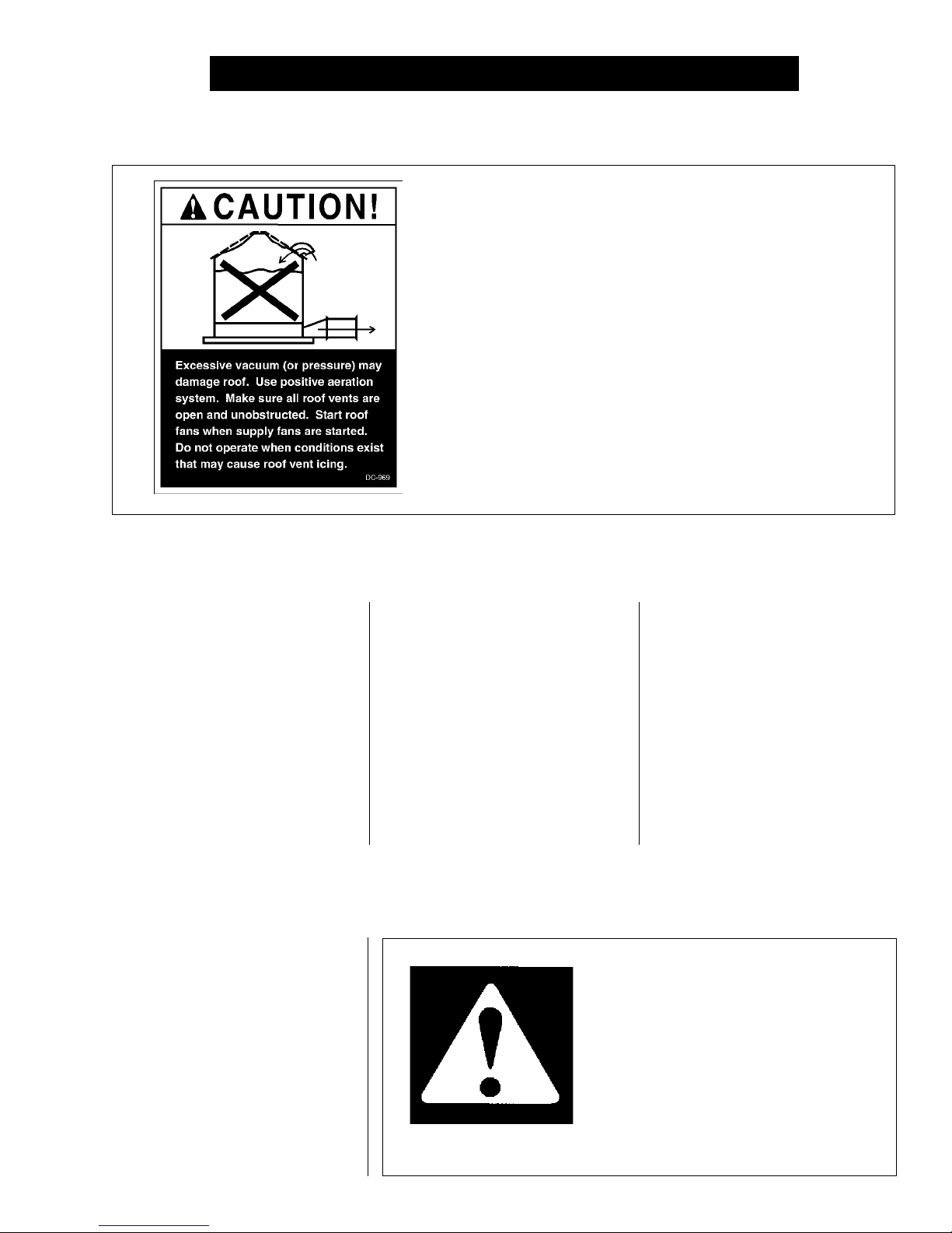
ROOF DAMAGE WARNING AND DISCLAIMER
GSI DOES NOT WARRANT ANY ROOF DAMAGE CAUSED
BY EXCESSIVE VACUUM OR INTERNAL PRESSURE FROM
FANS OR OTHER AIR MOVING SYSTEMS. ADEQUATE
VENTILATION AND/OR "MAKEUP AIR" DEVICES SHOULD
BE PROVIDED FOR ALL POWERED AIR HANDLING SYS-
TEMS. GSI DOES NOT RECOMMEND THE USE OF DOWN-
WARD FLOW SYSTEMS (SUCTION). SEVERE ROOF DAM-
AGE CAN RESULT FROM ANY BLOCKAGE OF AIR PAS-
SAGES. RUNNING FANS DURING HIGH HUMIDITY/COLD
WEATHER CONDITIONS CAN CAUSE AIR EXHAUST OR
INTAKE PORTS TO FREEZE.
Thank you for choosing a GSI/
Airstream product. It is designed
to give excellent performance
and service for many years.
This manual describes the
operation of the Airstream Vane
Axial Fan. It is designed for me-
dium to high static pressures,
and comes equipped with a 3450
RPM motor.
The symbol shown is used to call
your attention to instructions con-
cerning your personal safety. Watch
for this symbol; it points out impor-
tant safety precautions. It means
"ATTENTION", "WARNING", "CAU-
TION", and "DANGER". Read the
message and be cautious to the
possibility of personal injury or
death.
FAN OPERATION
The principal concern of the GSI
Group, Inc. ("GSI") is your safety and
the safety of others associated with
grain handling equipment. This
manual is written to help you under-
stand safe operating procedures,
and some of the problems that may
be encountered by the operator or
other personnel.
As owner and/or operator, it is
SAFETY ALERT SYMBOL
WARNING! BE ALERT!
Personnel operating or working around
electric fans should read this manual.
This manual must be delivered with the
equipment to its owner. Failure to read
this manual and its safety instructions is
a misuse of the equipment.
your responsibility to know what
requirements, hazards and pre-
cautions exist, and to inform all
personnel associated with the
equipment, or who are in the area.
Avoid any alterations to the equip-
ment. Such alterations may pro-
duce a very dangerous situation,
where serious injury or death may
occur.
5
Grain Systems, Inc. recommends
contacting your local power company,
and having a representative survey
your installation so the wiring is com-
patible with their system, and ad-
equate power is supplied to your unit.
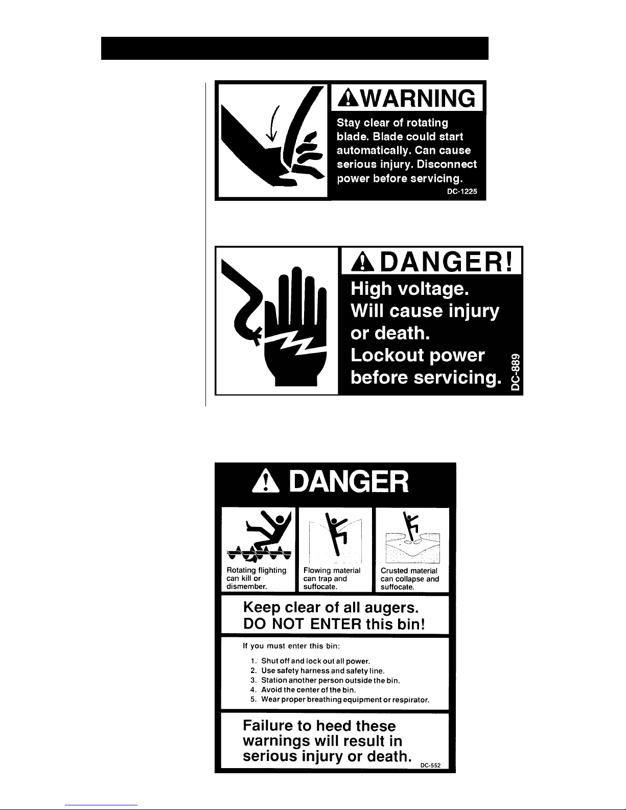
Safety decals should be read
and understood by all people in the
grain handling area. The bottom
right decal should be present on the
inside bin door cover of the two ring
door, 24" porthole door cover and
the roof manway cover.
If a decal is damaged or is miss-
ing contact:
Grain Systems, Inc.
1004 E. Illinois St.
Assumption, IL 62510
217-226-4421
A free replacement will be sent to you.
SAFETY ALERT DECALS
6
INSTALLATION INSTRUCTIONS
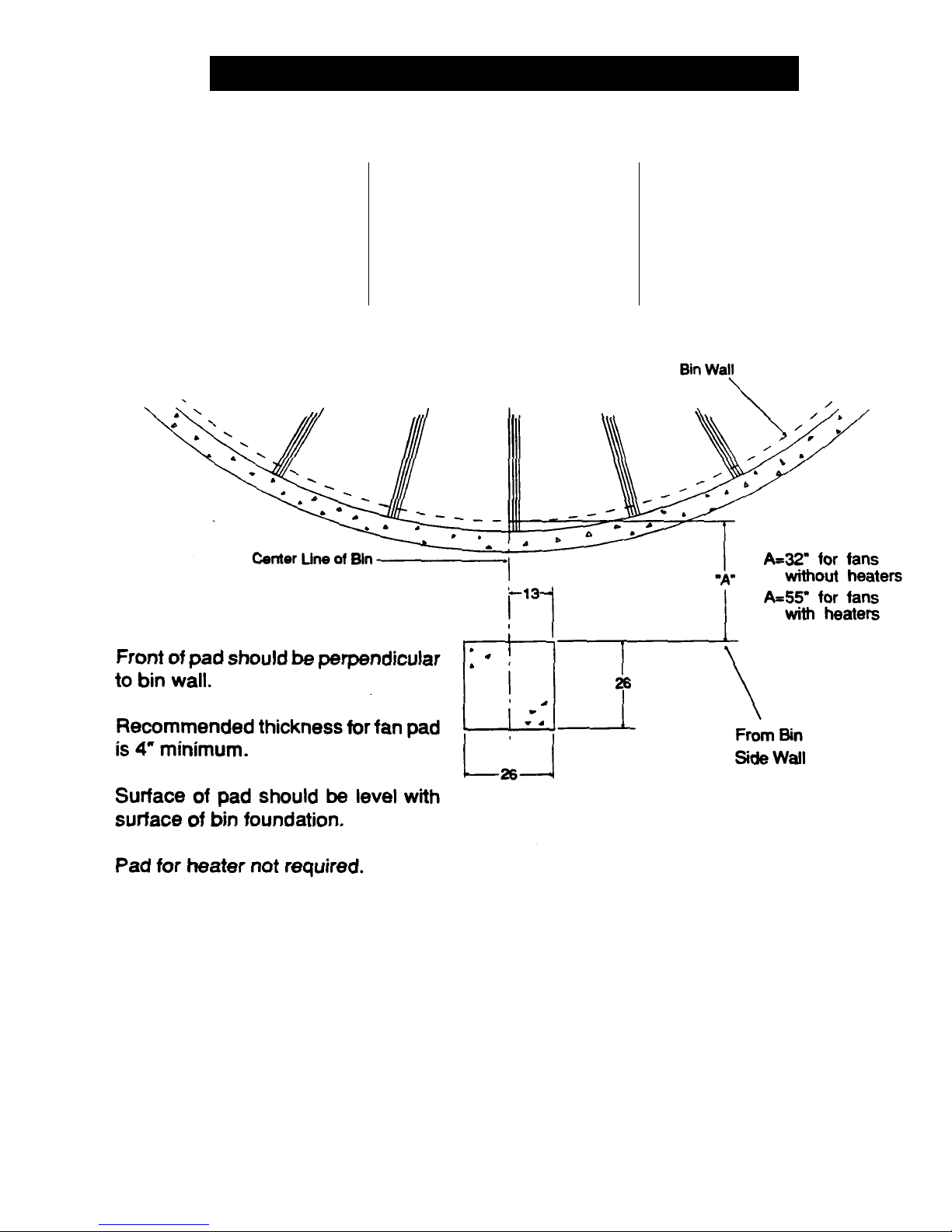
FAN PAD LOCATION
FOR USE WITH
TR-6918 & TR-6919
OVAL TRANSITION
Fan pad should be poured level with
top of bin foundation for all vane
axial fans 18" through 26" diameter.
The pad for Airstream heaters is not
required. If a vane axial heater may
be installed at a later date, then it
would be recommended to pour fan
pad 26" wide and 52" long. Fan should
be centered on center line of bin.
IMPORTANT! FAN PAD AND FAN
MUST BE LEVEL AND SMOOTH
FOR PROPER OPERATION. VI-
BRATION PROBLEMS CAN RE-
SULT FROM IMPROPER FAN LEV-
ELING.
Figure 1: Fan pad installation guidelines.
7

INSTALLATION INSTRUCTIONS
CHECKLIST BEFORE
INSTALLING THE FAN
1. One of the most important fac-
tors for installation is providing
adequate power to run the unit.
Undersized wire can lead to
voltage drop and can cause
motor overheating and short-
ened life. Therefore, it is neces-
sary to know the distance from
the unit to available transformer
and the horsepower of your fan
unit. These two factors will de-
termine the size of wire needed
for efficient operation. See Fan
ALWAYS DISCONNECT
Specifications on the following
page.
2. Grain Systems, Inc. recommends
contacting your local power com-
pany, and having a representa-
tive survey your installation so
the wiring is compatible with
their system, and adequate power
is supplied to your unit.
3. Each fan motor should be wired
through a fused or circuit
breaker disconnect switch.
4. Refer to Fan Specifications on
page 9 for the recommended
slow blow fuse or breaker size
to use when installing your par-
ticular fan.
5. Standard electrical safety prac-
tices and codes should be used.
(Refer to National Electrical Code
Standard Handbook by National
Fire Protection Association).
INSTALLATION
1. Be sure that the disconnect and
the fan are well grounded. See
machine to earth ground on
page 11.
2. Rotate the fan blade to be sure
that it revolves easily and does
not rub the housing.
3. Check all fasteners on motor
mounts, fan blades and other
bolted items to make sure they
are tight. If any are loose, check
for proper clearance and re-
tighten fasteners. They may
have loosened in shipping.
4. Fans should be mounted to set
level and solid. It may be nec-
essary to shim one or more cor-
ners of the foot mount to achieve
a solid mounting. Fans not sol-
idly mounted and properly
shimmed may have excess vi-
bration in them.
AND LOCK OUT POWER
BEFORE WORKING ON OR
AROUND HEATER
8
6. A qualified electrician should
make all electrical wiring instal-
lations.
5. Check and retighten all electri-
cal connections. They may have
loosened in shipping.
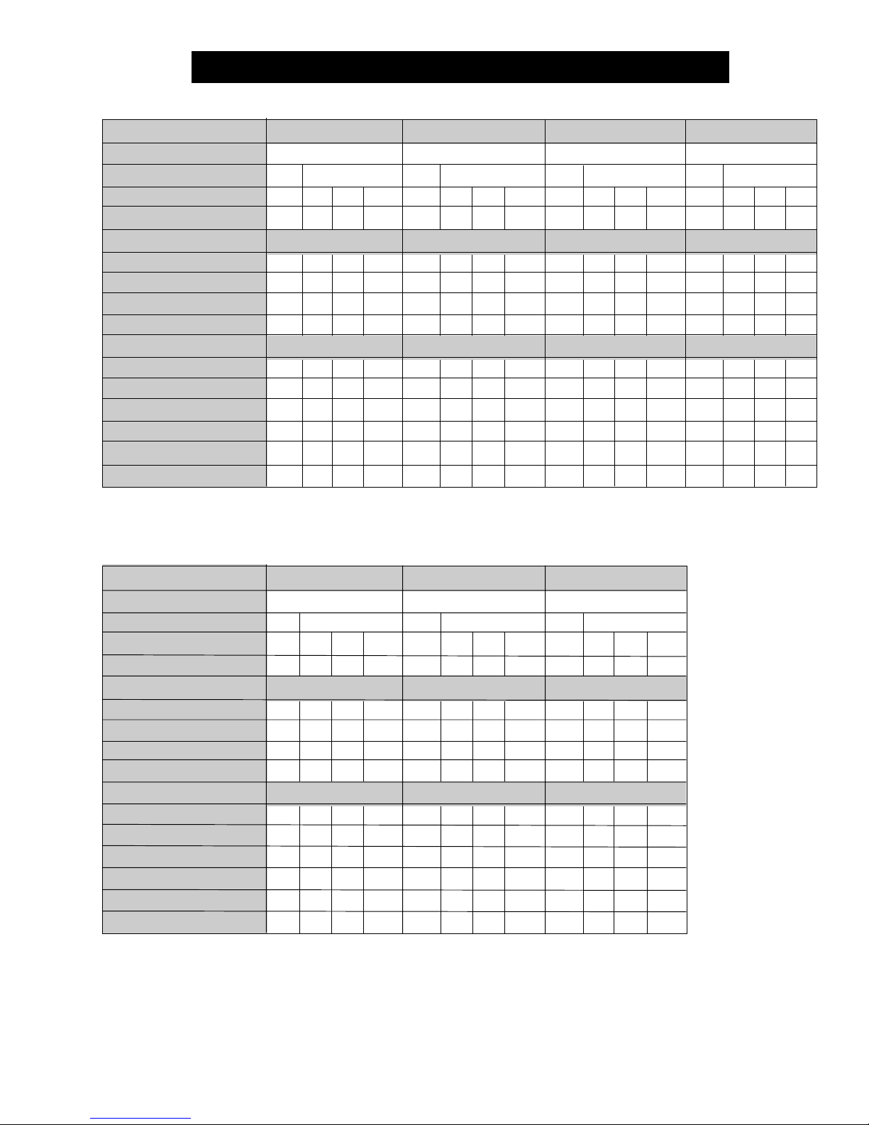
FAN SPECIFICATIONS
FAN HORSEPOWER
RPM
PHASE
VOLTS
FULL LOAD AMPS
MINIMUM WIRE SIZE
50' RUN
100' RUN
200' RUN
300' RUN
MINIMUM WIRE SIZE
50' RUN
100' RUN
200' RUN
300' RUN
FUSE SIZE (SLOW BLOW)
BREAKER SIZE
3/4
3450
230
2.6
14
14
14
14
14
14
14
12
10
15
3
460
1.3
14
14
14
14
14
14
14
14
5
10
1
230
5.5
Copper Wire
14
14
12
10
Aluminum Wire
14
14
10
8
15
20
575
1.0
14
14
14
14
14
14
14
14
5
10
1
3450
230
3.0
14
14
14
14
14
14
14
12
10
15
3
460
1.5
14
14
14
14
14
14
14
14
5
10
1
230
5.5
Copper Wire
14
14
12
10
Aluminum Wire
14
14
10
8
15
20
575
1.2
14
14
14
14
14
14
14
14
5
10
1.1/2
3450
230
4.6
14
14
12
10
12
12
10
10
10
15
3
460
2.3
14
14
14
12
14
12
12
12
5
10
1
230
7.5
Copper Wire
14
12
8
6
Aluminum Wire
12
10
6
4
15
20
575
1.8
14
14
14
12
14
14
12
12
5
10
3
3450
230
7.4
12
12
10
8
12
10
10
8
15
20
3
460
3.7
14
12
12
10
12
12
10
10
10
15
1
230
15
Copper Wire
12
10
8
6
Aluminum Wire
12
8
6
4
30
40
575
3
14
12
12
10
12
12
10
10
10
15
FAN HORSEPOWER
RPM
PHASE
VOLTS
FULL LOAD AMPS
MINIMUM WIRE SIZE
50' RUN
100' RUN
200' RUN
300' RUN
MINIMUM WIRE SIZE
50' RUN
100' RUN
200' RUN
300' RUN
FUSE SIZE (SLOW BLOW)
BREAKER SIZE
7
3450
1
230
30
Copper Wire
10
8
4
4
Aluminum Wire
8
6
3
2
40
60
3
23018460
9
12
12
10
12
8
10
6
8
10
12
8
10
6
10
4
8
25
15
30
15
575
6.9
12
12
12
10
12
12
10
10
15
15
10
3450
1
230
47
Copper Wire
10
6
4
2
Aluminum Wire
8
4
2
0
60
80
3
23025460
13
10
12
8
10
6
10
4
8
10
12
8
10
4
8
2
6
30
20
40
20
575
9.6
12
12
10
8
12
10
10
8
15
20
15
3450
1
230
57
Copper Wire
8
6
2
0
Aluminum Wire
6
4
0
00
75
100
3
23032460
16
8
12
6
10
4
10
4
8
8
10
6
8
4
6
2
4
40
20
60
30
575
14
12
12
10
10
10
10
8
6
20
20
9
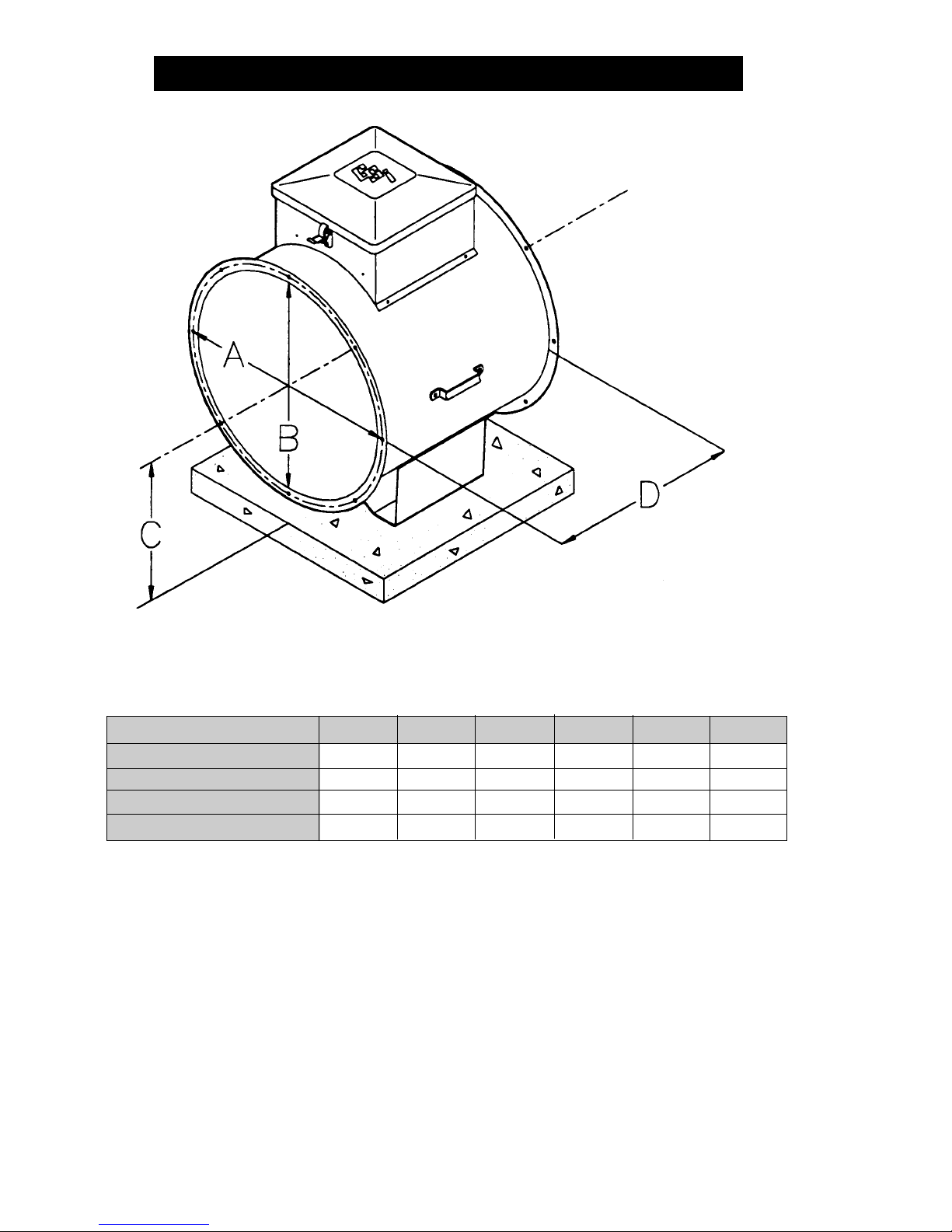
FAN SPECIFICATIONS
FAN
A (BOLT CIRCLE)
B (INSIDE DIA)
C (CL TO BOTTOM OF LEG)
D (LENGTH)
Note: All Dimensions in inches.
Figure 2: Fan dimensions
12" Dia
12.3/4
11.7/8
8
14.1/8
14" Dia
15.1/8
14.1/8
10
14.1/8
18" Dia
19.1/2
18.1/4
13.5/16
22
24" Dia
25.3/4
24.1/4
15.3/8
23.1/2
26" Dia
27.11/16
26.5/16
16.7/8
20.1/4
28" Dia
29.5/8
28.1/8
18.1/8
26
10
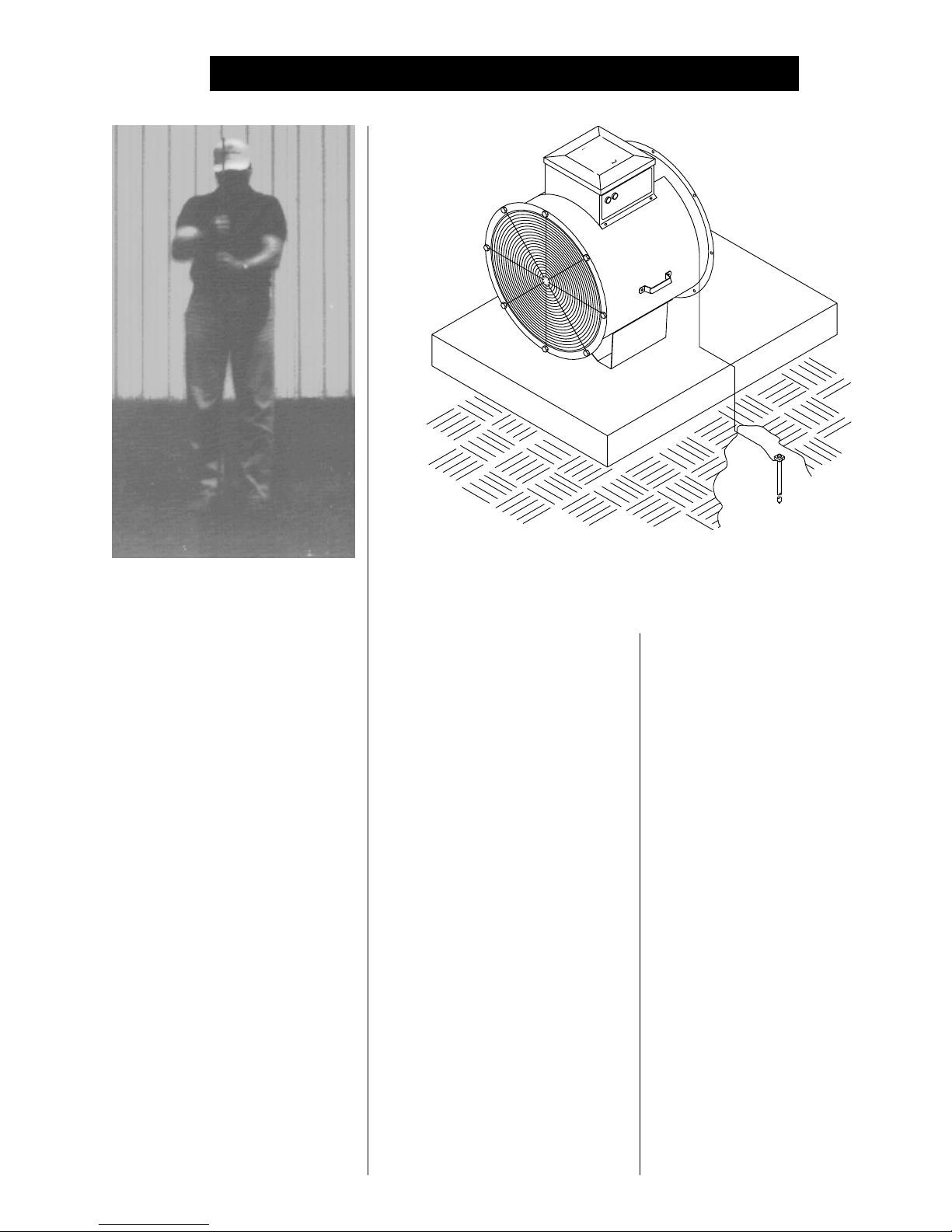
FAN INSTALLATION
Dig a hole large enough to hold 1
or 2 gallons of water. Work the
ground rod into the earth until it is
completely in the ground.
MACHINE TO EARTH
GROUND
It is very important that a machine
to earth ground rod be installed at
the fan. This is true even if there is
a ground at the pole 15 feet away.
This ground needs to be as close to
the fan as possible, but no more than
8 feet away. The ground rod should
be connected to the fan control panel
with at least a #6 solid bare copper
ground wire, or in accordance with
local requirements. The machine to
earth ground provides additional
safety if there is a short. It also pro-
vides the grounding necessary for
long life and operation of the solid
state circuit boards used on control
circuits and the electronic ignition
systems.
Figure 3: Use a #6 or approved size bare copper ground wire. Install a 5/8"
diameter 8' long copper-clad ground rod, 2' away from the foundation and 1'
below the surface of the ground or in accordance with local requirements.
PROPER INSTALLATION
OF THE GROUND ROD
(Ground rods and wires are not sup-
plied by Airstream). It is recom-
mended that the rod not be driven into
dry ground. The following steps en-
sure proper ground rod installation:
1. Dig a hole large enough to hold
1 to 2 gallons of water.
2. Fill hole with water.
3. Insert rod through water and jab
it into the ground.
4. Continue jabbing the rod up and
down, the water will work its way
down the hole, making it pos-
sible to work the rod completely
into the ground. This method of
installing the rod gives a good
conductive bond with the sur-
rounding soil.
5. Connect the bare copper ground
wire to the rod with the proper
ground rod clamp.
6. Connect the bare ground wire to
the fan control boxes with a
grounding lug. See Figure 3.
7. Ground wire must not have any
breaks or splices. Insulated
wire is not recommended for
grounding.
PREVIOUSLY INSTALLED
UNITS
It is recommended that previously
installed units be checked to see that
a machine to earth ground has been
installed by an electrician.
11
FAN OPERATION
START-UP
On initial start-up of the fan, run it
momentarily to make sure that the
fan blade is rotating in the proper
direction and airflow is correct. If not,
change motor direction using in-
structions on the motor.
Proper installation and start-up
ensures many years of trouble-free
operation.
MAINTAINING GRAIN
QUALITY
To properly maintain the quality of
stored grain, it is necessary to keep
the grain dry, cool and insect free.
Any one of these problems can con-
tribute to spoilage. Wet, warm grain
promotes insect growth as well as
grain spoilage. Cool, dry grain can
keep for long periods of time.
It is recommended that the grain
be kept cool (avoid freezing as freez-
ing can reduce quality). Grain should
be cooled through the fall and winter,
warmed in the spring and summer.
GRAIN STORAGE
Average grain temperature should
be above 35°F in the winter and below 65°F in the summer. Always try
to keep the grain within 10-15°F of
the average monthly outside tem-
perature. This means grain may
need to be aerated on warm days
during the winter to stay above 35°F
when freezing temperatures are pre-
dominate. During the summer it may
be necessary to aerate the grain on
cool nights, so the 65°F temperature
is not exceeded during the hot days
of summer.
Conditions and requirements may
vary from area to area. We suggest
that you contact your local Agriculture
Extension Office or State Ag. Univer-
sity for more exact guidelines.
If the grain is to be stored more
than one year, it has to be recooled
the following fall and winter, repeat-
ing the process as long as the grain
is in storage. Frequent and regu-
lar inspection (at least weekly
during fall and spring) is the best
prevention against grain spoilage).
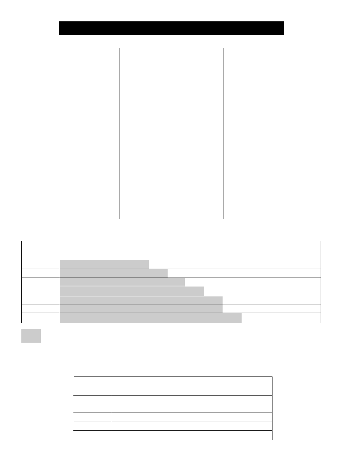
EQUILIBRIUM MOISTURE CHART
Air
Temperature
°°
20
°F
°°
°°
30
°F
°°
°°
40
°F
°°
°°
50
°F
°°
°°
60
°F
°°
°°
70
°F
°°
°°
80
°F
°°
Safe moisture for normal winter storage of shelled corn is about 15%. Grain to be stored through the summer or
long term, needs to be 1 to 3 points dryer.
35
11.2
10.8
10.5
10.1
9.7
9.0
8.3
40
11.7
11.3
11.0
10.6
10.2
9.7
9.1
45
12.7
12.2
11.7
11.3
10.9
10.4
9.8
50
13.7
13.1
12.5
12.0
11.6
11.1
10.5
14.5
13.9
13.3
12.7
12.1
11.5
10.8
Percentage Relative Humidity
55
60
15.1
14.6
14.0
13.3
12.7
12.0
11.2
65
16.2
15.5
14.8
14.1
13.4
12.8
12.1
17.1
16.4
15.5
14.8
14.2
13.5
13.0
70
75
18.0
17.4
16.6
15.8
15.0
14.5
13.9
80
19.6
18.7
17.8
16.9
16.0
15.4
14.8
85
21.2
20.2
19.4
18.6
17.8
16.8
15.8
90
23.5
22.5
21.5
20.5
19.5
18.5
17.4
95
25.8
25.0
24.2
23.4
22.6
21.3
20.0
100
29.1
28.3
27.5
26.7
25.9
24.5
22.8
APPROXIMATE ALLOWABLE HOLDING TIME FOR FIELD-SHELLED CORN,
TO MAINTAIN GRADE*
°°
Grain (
°F)
°°
Temperature
°°
40
°F
°°
°°
50
°F
°°
°°
60
°F
°°
°°
70
°F
°°
°°
80
°F
°°
15%
days
898
451
242
147
109
18%
days
195
102
63
37
27
20%
days
85
46
26
13
10
22%
days
54
28
16
8
6
24%
days
38
19
10
5
4
26%
days
28
16
8
4
3
28%
days
24
13
6.5
3.5
2.5
30%
days
20
11
5.5
3
2
*Allowable holding time for field-shelled corn at various grain temperatures and moisture
12
 Loading...