

Page 1

Dryer Start-Up
Quick Reference Guide for 1000,
2000 and 3000 Series Dryer Models
PNEG-523
Date: 09-07-07
PNEG-523
Page 2

2 PNEG-523 Dryer Start-Up
Page 3

Table of Contents
Contents
Chapter 1 Introduction ........................................................................................................................................ 4
Chapter 2 Safety ..................................................................................................................................................5
Safety Guidelines ............................................................................................................................... 5
Safety Instructions .............................................................................................................................. 6
Chapter 3 Decals ................................................................................................................................................. 8
Safety Alert Decals ............................................................................................................................. 8
Chapter 4 Start-Up Procedure ..........................................................................................................................10
Full Start-Up Check .......................................................................................................................... 10
Filling the Dryer .......................................................................................................................... ... ... 10
Starting the Dryer .......................................................................................................................... ... 11
Adjusting the Temperature ............................................................................................................... 11
Full Heat Continuous Flow Operation .............................................................................................. 12
1100 and 1200 Series Continuous Flow Metering Roll Settings ...................................................... 13
Dry and Cool Continuous Flow Operation for Dryers with Two or More Fans ................................. 14
1100 and 1200 Series Continuous Flow Metering Roll Settings ...................................................... 15
Adjusting the Moisture Control ......................................................................................................... 15
Chapter 5 Quick Reference ..............................................................................................................................17
Electronic Monitoring Control System - Quick Reference ................................................................ 17
Start-Up - Quick Reference .............................................................................................................. 18
Starting the Drying Process for Full Heat Operation - Quick Reference .......................................... 19
Chapter 6 FAQs ................................................................................................................................................. 20
Chapter 7 Warranty ...........................................................................................................................................21
PNEG-523 Dryer Start-Up 3
Page 4

1. Introduction
Thank you for choosing a GSI product. It is designed to provide excellent performance and service for
many years.
This manual describes the start-up of 1000, 2000 and 3000 series model dryers. When installed and
operated properly and according to specifications, this unit will provide many years of dependable
service.
READ THIS MANUAL carefully to learn how to properly use and install equipment. Failure to do so could
result in personal injury or equipment damage.
INSPECT the shipment immediately upon arrival. The customer is responsible for ensuring that all
quantities are correct. The customer should report and note any damage or shortage on the bill of lading
to justify their claim to the transport company.
THIS MANUAL SHOULD BE CONSIDERED a permanent part of your equipment and should be easily
accessible when needed.
This warranty provides you the assurance that the company will back its products when defects appear
within the warranty period. In some circumstances, the company also provide s field improvements, often
without charge to the customer, even if the product is out of warranty. Should the equipment be abused,
or modified to change its performance beyond the factory specifications, the warranty will be come void
and field improvements may be denied.
4 PNEG-523 Dryer Start-Up
Page 5
2. Safety
Safety Guidelines
This manual contains information that is important for you, the owner/operator, to know and understand.
This information relates to protecting personal safety and preventing equipment problems. It is the
responsibility of the owner/operator to inform anyone operating or working in the area of this equipment
of these safety guidelines. To help you recognize this information, we use the symbols that are defined
below. Please read the manual and pay attention to these sections. Failure to read this manual and its
safety instructions is a misuse of the equipment and may lead to serious injury or death.
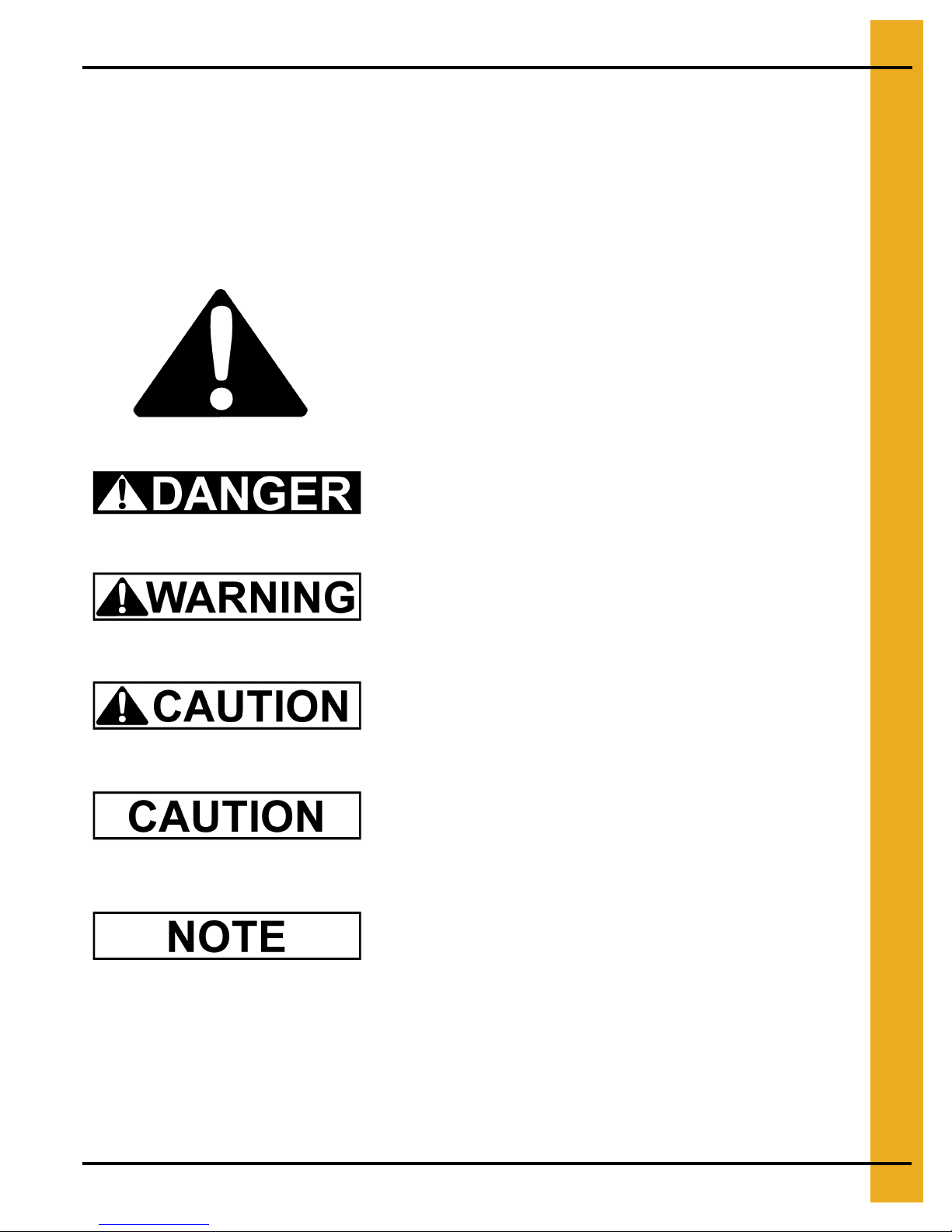
This is the safety alert symbol. It is used to alert you
to potential personal injury hazards. Obey all safety
messages that follow this symbol to avoid possible
injury or death.
DANGER indicates an imminently hazardous situation
which, if not avoided, will result in death or serious injury.
WARNING indicates a potentially hazardous situation
which, if not avoided, could result in death or serious injury.
CAUTION indicates a potentially hazardous situation which,
if not avoided, may result in minor or moderate injury.
CAUTION used without the safety alert symbol indicates a
potentially hazardous situation which, if not avoided, may
result in property damage.
NOTE indicates information about the equipment that you
should pay special attention.
PNEG-523 Dryer Start-Up 5
Page 6
2. Safety
Safety Instructions
Our foremost concern is your safety and the safety of others associated with this equipment. We want
to keep you as a customer. This manual is to help you understand safe operating procedures and some
problems which may be encountered by the operator and other personnel.
As owner and/or operator, it is your responsibility to know what requ irements, hazards and p recautions
exist, and to inform all personnel associated with the equipment or in the area . Safety precautions may
be required from the personnel. Avoid any alterations to the equipment. Such alterations may produce
a very dangerous situation where SERIOUS INJURY or DEATH may occur.
This equipment shall be installed in accordance with the current installation codes and applicable
regulations which should be carefully followed in all cases. Authorities having jurisdiction should be
consulted before installations are made.
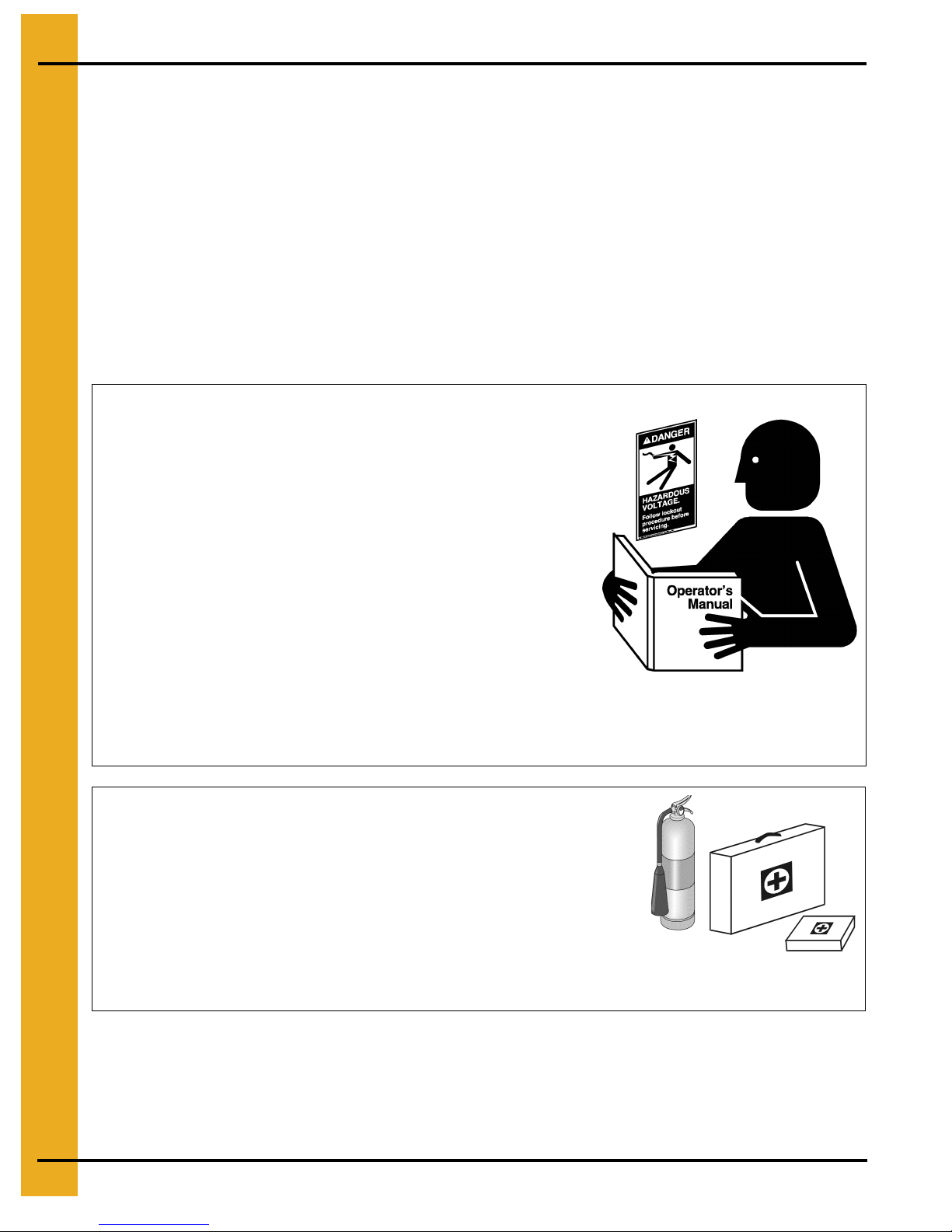
Follow Safety Instructions
Carefully read all safety messages in this manual and
safety signs on your machine. Keep signs in good
condition. Replace missing or damaged safety signs. Be
sure new equipment components and repair parts include
the current safety signs. Replacement safety signs are
available from the manufacturer.
Learn how to operate the machine and how to use controls
properly. Do not let anyone operate without instruction.
Keep your machinery in proper working condition.
Unauthorized modifications to the machine may impair
the function and/or safety and affect machine life.
If you do not understand any part of this manual or need
assistance, contact your dealer.
Prepare for Emergencies
Be prepared if fire starts.
Keep a first aid kit and fire extinguisher handy.
Keep emergency numbers for doctors, ambulance service,
hospital and fire department near your telephone.
Read and Understand Manual
Keep Emergency Equipment
Quickly Accessible
6 PNEG-523 Dryer Start-Up
Page 7
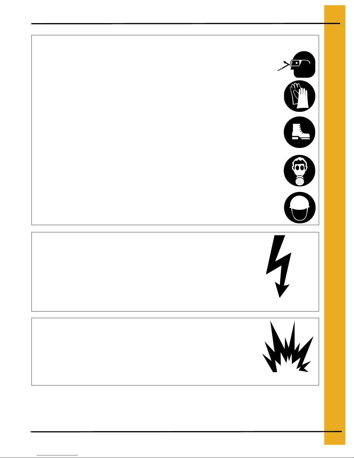
Wear Protective Clothing
Wear close fitting clothing and safety equipment appropriate
to the job.
Remove all jewelry.
2. Safety
Eye Protection
Long hair should be tied up and back.
Safety glasses should be worn at all times to protect eyes
from debris.
Wear gloves to protect your hands from sharp edges on
plastic or steel parts.
Wear steel toe boots to help protect your feet from falling
debris. Tuck in any loose or dangling shoe strings.
A respirator may be needed to prevent breathing potentially
toxic fumes and dust.
Wear hard hat to help protect your head.
Install and Operate Electrical Equipment Properly
Electrical controls should be installed by a qualified electrician
and must meet the standards set by the National Electrical Code
and all local and state codes.
Gloves
Steel Toe Boots
Respirator
Hard Hat
Disconnect and lock out all power sources before installing
wires/cables or servicing equipment.
Electric Shock Hazard
Install and Operate Gas-Fired Equipment Properly
Fuel supply should be installed by a qualified gas
technician and must meet local and state codes for
gaseous fuel supplies.
Disconnect and lock out all fuel sources before
servicing equipment.
PNEG-523 Dryer Start-Up 7
Explosive Gases
Page 8
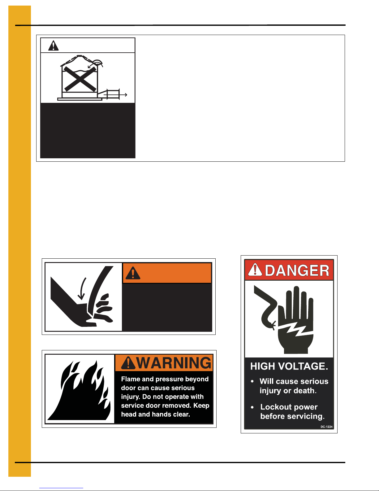
3. Decals
CAUTION!
Roof Damage War ning
GSI cannot warrant any roof damages due to excessive vacuum
or internal pressure caused by fans or other air moving systems.
Adequate ventilation and/or “make-up air” devices should be provided for all powered air handling systems. GSI does not recommend the use of downward flow systems. Severe roof structural
damage can result from any blockage of air passages. Running
Excessive vacuum (or pressure) may
damage roof. Use positive aeration
system. Make sure all roof vents are
open and unobstructed. Start roof
fans when supply fans are started.
Do not operate when conditions exist
that may cause roof vent icing.
fans during high humidity/cold weather conditions can cause air
exhaust or intake ports to freeze over.
DC-969
Safety Alert Decals
If a decal has been damaged or is missing contact:
GSI Group
1004 E. Illinois St.
Assumption, IL 62510
217-226-4421
A free replacement will be sent to you.
WARNING
Stay clear of rotating
blade. Blade could start
automatically. Can cause
serious injury. Disconnect
power before servicing.
DC-1225
DC-1227
8 PNEG-523 Dryer Start-Up
Page 9
3. Decals
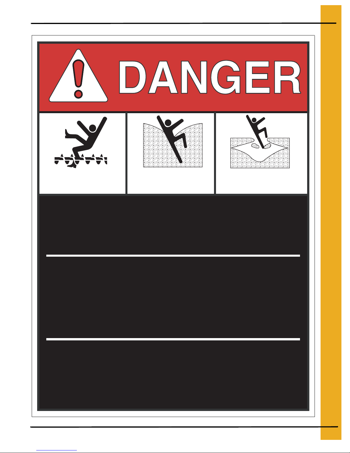
Rotating flighting will
kill or dismember.
Flowing material will
trap and suffocate.
Crusted material will
collapse and suffocate.
Keep clear of all augers.
DO NOT ENTER this bin!
If you must enter the bin:
1. Shut off and lock out all power.
2. Use a safety harness and safety line.
3. Station another person outside the bin.
4. Avoid the center of the bin.
5. Wear proper breathing equipment or respirator.
Failure to heed these
warnings will result in
serious injury or death.
PNEG-523 Dryer Start-Up 9
DC-GBC-1A
Page 10

4. Start-Up Procedure
Standard electrical safety practices and codes should be followed when working with a dryer. Refer to
the National Electric Code Standard Handbook by the National Fire Protection Association. A qualified
electrician must make all wiring installations.
Always disconnect and lock out power before working on or around dryer.
Full Start-Up Check
This start-up procedure assumes the following:
1. You have read and understand the DRYER OPERATION AND SERVICE MANUAL.
2. You have taken special note of all SAFETY PRECAUTIONS.
3. All safety shields are in place.
4. All meter roll access doors have been opened and all foreign objects have been removed.
5. You have done a pre-start-up check.
6. All motors have been checked for proper rotation.
7. All heaters have been test fired.
8. The fuel has been turned ON at the tank.
9. The electric power has been turned ON.
10. The main disconnect switch on the dryer is ON.
11. There is wet grain in the wet holding bin.
12. Incoming grain moisture is known.
13. Dry grain take away equipment is in place.
14. Grain is going to the proper bin.
15. Switches other than fuel, electric power and main disconnect have been set to the OFF position.
16. The load mercury switch box is installed with the side stamped “UP”, in the up position.
Filling the Dryer
1. Turn the green CONTROL POWER knob to ON. It will light up and scroll through four (4) screens
and finish by displaying the time and date.
2. Turn the DRYING MODE switch to CONTINUOUS FLOW.
3. Push the RESET button on the computer keypad to activate the computer.
4. Make sure the UNLOAD switch is in the OFF position.
5. Push the DRYER POWER start switch; it will light up.
6. Turn the LOAD AUGER switch to the MANUAL position to fill the dryer. The load auger will start
and run until the dryer is full and then shut off automatically. (If the switch is set to the AUTO
position the dryer will shut down each time the Out of Grain timer times out and will have to
be restarted).
7. When the dryer has filled, turn the LOAD AUGER switch to the AUTO position.
10 PNEG-523 Dryer Start-Up
Page 11

4. Start-Up Procedure
Starting the Dryer
This is the start-up procedure for a cold start on wet grain and continuous flow operation.
1. Set the MAXON, or FAST ACTION HAND VALVE, on the incoming fuel line to the ON position.
2. Make sure the MOISTURE CONTROL switch is in the OFF position.
3. Turn the FAN switch (or switches if a multi-fan dryer) to the ON position. The light in the switch will
turn on when the fan reaches approximately half speed.
4. Adjust the AIR PRESSURE switch if necessary.
5. Turn the HEATER switch (or switches if a multi-fan dryer) to the ON position. The heater will purge
for approximately 10 seconds and then ignite. The light in the heater switch will come on during
ignition and will stay on if the heater ignites successfully. If the heater does not ignite, the light will
go OFF after the trial for ignition and the dryer will shut down. If this happens, check the gas supply
and all valves in the fuel line to make sure they are ON.
Adjusting the Temperature
1. Set the HIGH-LOW FIRE PLENUM THERMOSTAT on the left side of the dryer to the desired
drying temperature (180° to 200°). On multiple fan dryers set the heat chambers 30° to 60° apart:
hottest at the top and coolest at the bottom.
2. On LP gas models adjust the gas pressure using the PRESSURE REGULATOR, High Fire, on the
burner fuel line, so the burner will reach the thermostat setting and switch to Low Fire. Pressure up
to 25 lbs. may be required. Natural gas does not have a regulator but uses a LARGE BALL VALVE
close to the vertical supply line for adjustment. Pressure up to 18 lbs. may be required.
On LP gas models adjust the small RED HANDLED BALL VALVE, Low Fire, so the burner
maintains flame then switches back to High Fire. Natural gas has a BALL VALVE close to the
burner control box for Low Fire adjustment.
3. Adjust the burner pressure so that the burners cycle four (4) times per minute. Each cycle should
be approximately 10 seconds on High and approximately 5 seconds on Low. Four (4) of these
cycles should occur per minute. When on High Fire, increasing the pressure with the pressure
regulator DECREASES the time spent on High Fire. When on Low Fire, increasing the Low Fire
pressure with the RED BALL VALVE INCREASES the time spent on Low Fire.
4. On LP gas models adjust the vaporizor so the fuel pipes going to the burner from the regulator are
warm to the touch but are neither hot nor cold. The vaporizor can be adjusted two ways. First, by
loosening the bolt in the hinging mechanism and swinging it to a hotter o r cooler position. Second,
by loosening the two bolts in the hinge pipe and sliding the vaporizor in or out to a cooler or hotter
position. Either one or both methods may need to be used to get the vaporizor to the proper
temperature. Natural gas does not use a vaporizor.
PNEG-523 Dryer Start-Up 11
Page 12

4. Start-Up Procedure
Full Heat Continuous Flow Operation
1. Refer to the DRYER START-UP section of the Operator’s Manual. (CONTINUOUS FLOW METER
ROLL SETTINGS - FULL HEAT on Page 13.) There are settings for Initial Moisture, Moisture
Removed, Approximate Dry Time, 1 Speed, 2 Speed Low and 2 Speed High. Select the line that
indicates the initial moisture. These are the settings referred to throughout this start-up procedure.
2. Make sure the UNLOAD switch is OFF.
3. Make sure the MOISTURE CONTROL switch is OFF.
4. If the dryer is stopped press the dryer start switch to lock in the control circuit.
5. Turn the fan and burner switches to the “ON” position to run fans and burners. Be sure to adjust the
plenum temperature to 180°F for all burners. Run the fans and burners for about 10% longer than
the approximate dry time (from chart on Page 13) for the incoming moisture. Example: 10 pt.
removal from the chart is 54 minutes, plus 5.4 minutes (10%) equals 59.4 minutes (round up to 60).
6. Increase the drying temperature to a maximum of 210°F (corn) for single fan dryers. For multiple
fan dryers adjust the top burner to a maximum of 230°F (corn) and stage the temperature of the
lower burners down 30° per burner. Example: 3 fan dryer Top burner: 230°, Middle burner: 200°,
Bottom burner: 170°.
7. After this initial fan and burner run time set the unload switch to “1 SPEED” and set the HIGH
SPEED meter roll potentiometer to the setting for 1 SPEED (from chart on Page 13). Meter rolls
should start and grain will begin to flow from discharge of dryer. Run time for this step should be
the same as for the fan and burner time from Step 5 above. IT IS IMPORTANT NOT TO ADJUST
THE DRYER DURING THIS PERIOD. The grain discharging towards the end of this period will be
over dried, but it is necessary so that the corn moisture is staged properly and evenly in the dryer.
8. Turn the Moisture control switch to “ON”. Set the moisture control (grain) temperature to 100°F.
9. Turn the Unload switch to “2 SPEED”. Find the “2 SPEED HIGH” and “2 SPEED LOW” meter roll
settings on chart and set meter roll potentiometers accordingly. Allow the dryer to ru n for the time
established in step 5 and then sample the grain. If the dryer has been cycling regularly from high
to low and the grain is not coming out to moisture desired, then adjust the moisture control (grain)
temperature up or down 5° per point of moisture. Example: Moisture control is se t to 100°, desired
moisture is 15%, sampled moisture is 17%. Adjust moisture control to 110°. EVERY TIME AN
ADJUSTMENT IS MADE IT IS IMPERATIVE THAT THE DRYER IS ALLOWED TO RUN FOR THE
ESTABLISHED TIME IN ORDER FOR CHANGES TO TAKE AFFECT. Repeat this process as
necessary until desired moisture content is being discharged from dryer.
10. After the run time in Step 9, the moisture control and the meter roll speeds can be adjusted if
required. Each time an adjustment to the moisture control is made, it will take approximately the
time as shown in the example in Step 5 to see the results of this adjustment.
12 PNEG-523 Dryer Start-Up
Page 13
4. Start-Up Procedure
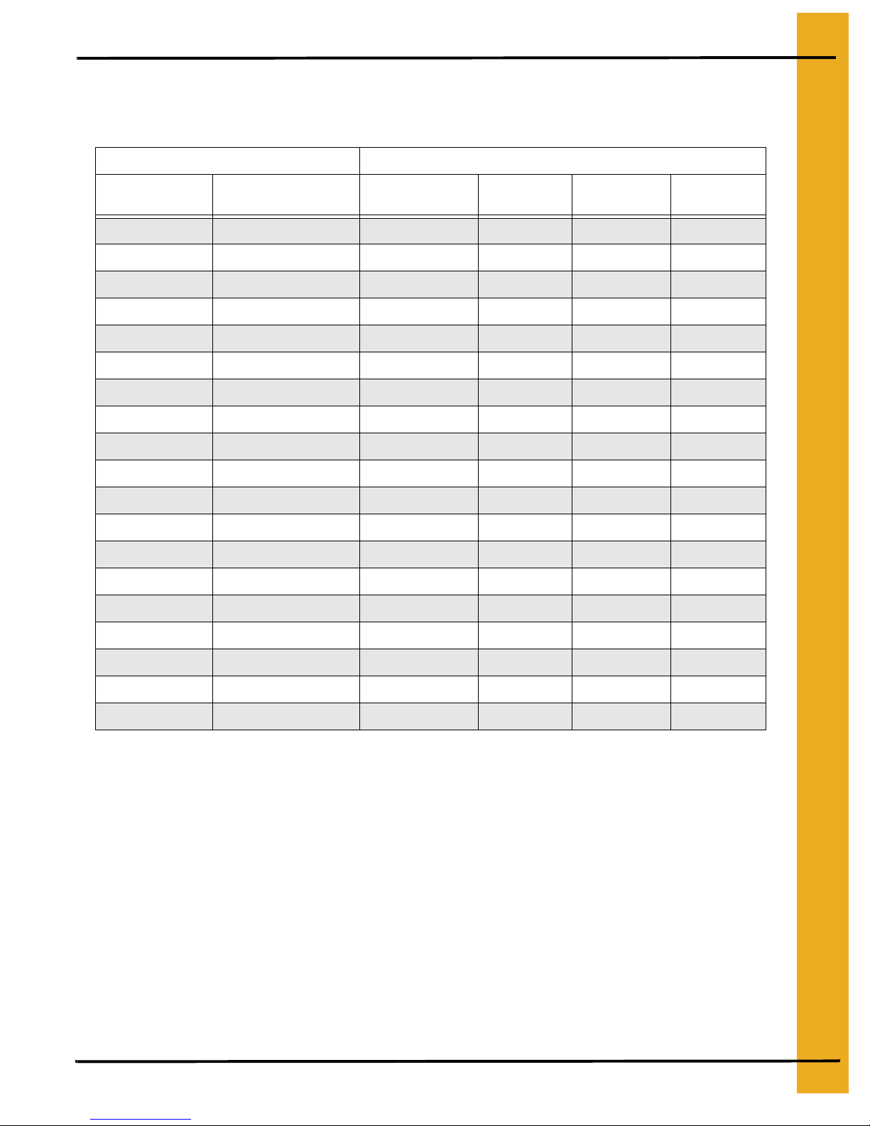
1100 and 1200 Series Continuous Flow Metering Roll Settings Full Heat
Full Heat
Initial Moisture Moisture Removed
17% 2 pts. 16 min. 625 317 875
18% 3 pts. 21 min. 476 270 775
19% 4 pts. 26 min. 385 241 675
20% 5 pts. 31.5 min. 317 213 575
21% 6 pts. 37 min. 270 196 476
22% 7 pts. 41.5 min. 241 185 385
23% 8 pts. 47 min. 213 172 317
24% 9 pts. 51 min. 196 161 270
25% 10 pts. 54 min. 185 150 241
26% 11 pts. 58 min. 172 140 213
27% 12 pts. 62 min. 161 132 196
28% 13 pts. 66.5 min. 150 123 185
29% 14 pts. 71.5 min. 140 116 172
30% 15 pts. 76 min. 132 110 161
Approximate
Dry Time
1 Speed 2 Speed Low 2 Speed High
31% 16 pts. 81 min. 123 104 150
32% 17 pts. 86 min. 116 100 140
33% 18 pts. 91 min. 110 096 132
34% 19 pts. 96 min. 104 087 123
35% 20 pts. 100 min. 100 082 116
These are approximate starting points.
PNEG-523 Dryer Start-Up 13
Page 14

4. Start-Up Procedure
Dry and Cool Continuous Flow Operation for Dryers with Two or
More Fans
1. Refer to the DRYER START-UP section in the Operator’s Manual (CONTINUOUS FLOW METER
ROLL SETTINGS - DRY and COOL on Page 15.) There are settings for Initial Moisture, Moisture
Removed, Approximate Dry Time, 1 Speed, 2 Speed Low, and 2 Speed High. Select the line that
has your initial starting moisture. These are the settings we will be referring to during this
start-up procedure.
2. Make sure the UNLOAD switch is OFF.
3. Make sure the MOISTURE CONTROL switch is OFF.
4. If the dryer is stopped press the dryer start switch to lock in the control circuit.
5. Run the bottom fan(s) and heater(s), which will be used for cooling later, for approximately 20
minutes. This will start drying and cool the bottom before beginning to discharge grain.
6. Run the remaining fans and burners at equal intervals for approximately 10% longer than the dry
time (refer chart on Page 15) required for the target moisture. Example: 10 pt. removal from chart
is 60 minutes, plus 6.0 minutes (10%) equals 66.0 minutes.
7. After the bottom fan(s) and heater(s) have run the required drying time, turn the bottom heater(s)
off. Cool this section for about 20 minutes. Increase the drying temperature to a maximum of 210°F
(corn) for single fan dryers. For multiple fan dryers adjust the top burner to a maximum of 230°F
(corn) and stage the temperature of the lower burners down 30° per burner. Example: 3 fan dryer
Top burner: 230°, Middle burner: 200°, Bottom burner: 170°.
8. Turn the UNLOAD switch to 1 SPEED and set the METER ROLL SPEED (HIGH SPEED)
potentiometer to the setting for 1 SPEED operation. Run time for this is about 10% longer than
the APPROXIMATE DRYING TIME required for the target moisture, as shown in the example in
Step 6. This allows the dryer to reach an even gradient moisture from top to bottom, without having
any highs or lows. It will, however, over-dry some of the corn.
9. DO NOT ATTEMPT TO ADJUST THE DRYER FOR MOISTURE DURING THIS PROCESS.
DOING SO WILL ESTABLISH HIGH AND LOW SWINGS IN THE MOISTURE CONTROL AND
WILL TAKE SEVERAL HOURS TO RESOLVE.
10. After the run time in Step 8 turn the MOISTURE CONTROL switch to the ON position. Set the
temperature to about 130°
11. Turn the UNLOAD switch to 2 SPEED. Set the METERING ROLL SPEED, LOW SPEED and HIGH
SPEED potentiometer to the settings listed in the chart on Page 15 for them. Let the dryer run on
these settings as shown in the example in Step 6 before trying to adjust moisture or meter roll
settings. These settings will not adjust moisture exactly as desired but will serve as a good starting
point for further adjustments. Slightly different moisture at the bottom of the storage bin is not
usually a problem if there is full floor aeration.
12. After the run time in Step 11, adjustments to the moisture control and the meter roll speeds can be
made if required. Each time an adjustment to the moisture control is made, it will take about the
time as shown in the example in Step 6 to see the results of this adjustment.
14 PNEG-523 Dryer Start-Up
Page 15
4. Start-Up Procedure
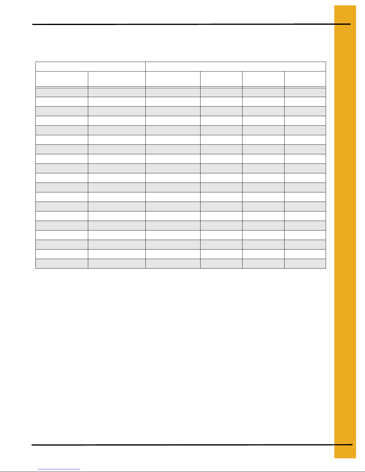
1100 and 1200 Series Continuous Flow Metering Roll Settings Dry and Cool
Dry and Cool
Initial Moisture Moisture Removed
17% 2 pts. 18 min. 363 187 650
18% 3 pts. 24 min. 272 163 550
19% 4 pts. 30 min. 218 145 450
20% 5 pts. 35 min. 187 131 363
21% 6 pts. 40 min. 163 119 272
22% 7 pts. 45 min. 145 109 218
23% 8 pts. 50 min. 131 101 187
24% 9 pts. 55 min. 1 19 093 163
25% 10 pts. 60 min. 109 087 145
26% 11 pts. 65 min. 101 082 131
27% 12 pts. 70 min. 093 077 119
28% 13 pts. 75 min. 087 073 109
29% 14 pts. 80 min. 082 069 101
30% 15 pts. 85 min. 077 065 093
31% 16 pts. 90 min. 073 061 087
32% 17 pts. 95 min. 069 057 082
33% 18 pts. 100 min. 065 053 077
34% 19 pts. 105 min. 062 049 073
35% 20 pts. 110 min. 059 045 069
These are approximate starting points.
Approximate
Dry Time
1 Speed 2 Speed Low 2 Speed High
Adjusting the Moisture Control
1. Each 5° on the MOISTURE CONTROL will change the output moisture by about 1%.
Example: 100° is set, and the result is 16% corn, but 17% is desired. Reduce the MOISTURE
CONTROL temperature by 5° to 95°. This should change the resulting corn to 17%. If drier corn is
desired, it is necessary to raise the temperature on the MOISTURE CONTROL.
2. There are four (4) sensors that are averaged together for detecting MOISTURE CONTROL
temperature: one on each side of the dryer in the front and one on each side of the dryer in the
back. These are located about 1/3 of the way up the grain column from the bottom an d about four
(4) inches in from the side.
3. The small lights behind the temperatures on the MOISTURE CONTROL indicate the temperature
of the grain at the sample point.
4. The two (2) lights in the center are green, the lights to the right or to the left of these are red.
5. When the grain temperature is cycling the dryer between HIGH and LOW SPEED and the green
lights on the moisture control are illuminated, the moisture setting is being maintained correctly.
PNEG-523 Dryer Start-Up 15
Page 16
4. Start-Up Procedure
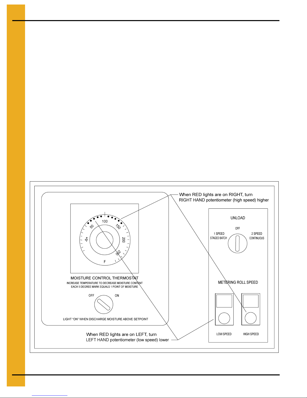
6. Set the METER ROLL SPEED in relation to the small red lights behind the temperatures on the
MOISTURE CONTROL.
7. RED lights to the left indicate that the grain at the sample point is too cool or wetter than desired.
To correct this, turn the (LOW SPEED) left potentiometer to a lower number. This will slow down
the meter rolls and dry the grain longer, warming it up.
8. RED lights to the right indicate that the grain at the sample point is too hot or dryer than desired.
To correct this, turn the (HIGH SPEED) right potentiometer to a higher number. This will speed up
the meter rolls and remove the grain quicker, cooling it down.
9. If the MOISTURE CONTROL switches to LOW and only stays on low for a minute or two and
switches back to HIGH, speed up the (LOW SPEED) left potentiometer. It is set too slow.
10. If the MOISTURE CONTROL switches to HIGH and only stays on low for a minute or two before it
switches back to LOW, slow down the (HIGH SPEED) right potentiometer. It is set too fast.
11. The MOISTURE CONTROL should stay on HIGH about 50% of the time and on LOW about 50%,
give or take 25%. There is a wide range of settings that will work. However, it should switch low to
high and back to maintain the desired moisture. A control that does not switch, will not maintain
evenly dried grain moisture when the incoming wet grain moisture varies.
12. When adjusting the meter roll speeds, do not change the speed more than 20 points at a time.
Figure 4A
16 PNEG-523 Dryer Start-Up
Page 17

5. Quick Reference
NOTE: Please read the manual for your dryer model before using the Quick Reference section.
Electronic Monitoring Control System - Quick Reference
IMPORTANT: To activate the controller after turning ON the control power, press the RESET button.
Setting the DRY, COOL, UNLOAD and OUT OF GRAIN timers:
• Press the DRY, COOL, UNLOAD or OUT OF GRAIN button.
• Press the MODIFY button.
• Press the INCREASE or DECREASE button to get desired setting.
• Press the ENTER button when desired setting is reached.
Setting the LOAD and UNLOAD DELAYS:
• Press the LOAD or UNLOAD button.
• Press the MODIFY button.
• Press the INCREASE or DECREASE button to get desired setting.
• Press the ENTER button when desired setting is reached.
Pressing the INCREASE and DECREASE buttons simultaneously will access the following programming
features:
• SAFETY CIRCUIT SHUT DOWN LOG
• DRYER MODEL NUMBER
•FAN DELAY
• BPH FACTOR
• METERING ROLL MONITOR DISABLING FEATURE
• AIR SWITCH DISABLING FEATURE
These features are accessed sequentially as listed above. Press the INCREASE or DECREASE buttons
to change a setting. Press the ENTER button to move from feature to feature.
Pressing and holding the RESET button for five (5) seconds will access the following programming
features:
• CALENDAR YEAR SETTING
• CALENDAR MONTH SETTING
• CALENDAR DAY SETTING
• CLOCK HOUR SETTING
• CLOCK MINUTE SETTING
• BUSHEL COUNTER RESET
• BATCH COUNTER RESET
These features are accessed sequentially as listed above. Press the INCREASE or DECREASE buttons
to change a setting. Press the ENTER button to move from feature to feature.
PNEG-523 Dryer Start-Up 17
Page 18

5. Quick Reference
Changing the Marquee on the LCD display:
• Press and hold the MODIFY button while turning on the control power.
• To change a character press the INCREASE or DECREASE button.
• To move the cursor to the right press the UNLOAD button.
• To move the cursor to the left press the DRY button.
• To delete a character press the COOL button.
• Press ENTER when the desired marquee is displayed.
Start-Up - Quick Reference
NOTE: Read and understand the full start-up procedure before using this Quick Reference Guide.
1. Control Power--ON
2. Drying Mode--CONTINUOUS FLOW
3. Push the computer RESET
4. Push dryer power START SWITCH
5. Unload--OFF
6. Load Auger--MANUAL, after dryer is full switch to AUTO
7. Maxon or Fast Action Hand Valve--ON
8. Moisture Control--OFF
9. Fan Switch--ON
10. Heater--ON
11. Plenum Thermostat--180° to 200° to start dryer
12. Adjust gas pressure regulators
13. Adjust vaporizors
18 PNEG-523 Dryer Start-Up
Page 19

5. Quick Reference
Starting the Drying Process for Full Heat Operation - Quick
Reference
NOTE: Check settings listed in main manual.
1. Unload--OFF
2. Moisture Control--OFF
3. Run fan and heater designated time plus 10% to 15%
4. After 1
5. Increase drying temperature--190° to 230° as desired
6. Readjust vaporizors if required
7. METER ROLL SPEED (HIGH SPEED)--set as chart specifies
8. After 2
9. Unload--2 SPEED
10. Meter roll--LOW SPEED and HIGH SPEED
11. After 3
12. Do not make corrections to the moisture more than once per hour
st
hour--Unload to 1 SPEED
nd
hour--Moisture Control--ON--set at about 100°
rd
hour--adjust moisture as required
PNEG-523 Dryer Start-Up 19
Page 20

6. FAQs
How much gas pressure is needed?
See Step 2 on Page 11 in the adjusting the temperature section.
How often should the burner cycle?
See Step 3 on Page 11 in the adjusting the temperature section.
How often do I make speed adjustments?
See Step 10 on Page 12 in the Full Heat Continuous Flow Operation section.
What temperature should I dry at?
See Step 8 on Page 14 in the Dry and Cool Continuous Flow Operation for Dryers with Two or More
Fans Section.
How do I set the moisture control?
See Step 1 on Page 15 in the Adjusting the Moisture Control Section.
20 PNEG-523 Dryer Start-Up
Page 21

7. Warranty
The GSI Group, Inc. Warranty
THE GSI GROUP, INC. (GSI) WARRANTS ALL PRODUCTS WHICH IT MANUFACTURES TO BE
FREE OF DEFECTS IN MATERIAL AND WORKMANSHIP UNDER NORMAL USAGE AND
CONDITIONS FOR A PERIOD OF 12 MONTHS AFTER RETAIL SALE TO THE ORIGINAL END USER.
THE PURCHASER’S SOLE REMEDY AND GSI’S ONLY OBLIGATION SHALL BE TO REPAIR OR
REPLACE, AT GSI’S OPTION AND EXPENSE, PRODUCTS THAT, IN GSI’S SOLE JUDGMENT,
CONTAIN A MATERIAL DEFECT DUE TO MATERIALS OR WORKMANSHIP. ALL DELIVERY AND
SHIPMENT CHARGES TO AND FROM GSI’S FACTORY WILL BE PURCHASER’S RESPONSIBILITY.
EXPENSES INCURRED BY OR ON BEHALF OF THE PURCHASER WITHOUT PRIOR WRITTEN
AUTHORIZATION FROM AN AUTHORIZED EMPLOYEE OF GSI SHALL BE THE SOLE
RESPONSIBILITY OF THE PURCHASER.
EXCEPT FOR THE LIMITED WARRANTY EXPRESSED ABOVE, GSI MAKES NO FURTHER
WARRANTY OF ANY KIND, EXPRESS OR IMPLIED, INCLUDING, WITHOUT LIMITATION,
WARRANTIES OF MERCHANTABILITY OR FITNESS FOR A PARTICULAR PURPOSE
OR USE IN CONNECTION WITH (I) PRODUCT MANUFACTURED OR SOLD BY GSI OR (II) ANY
ADVICE, INSTRUCTION, RECOMMENDATION OR SUGGESTION PROVIDED BY AN AGENT,
REPRESENTATIVE OR EMPLOYEE OF GSI REGARDING OR RELATED TO THE CONFIGURATION,
INSTALLATION, LAYOUT, SUITABILITY FOR A PARTICULAR PURPOSE, OR DESIGN OF
SUCH PRODUCTS.
GSI SHALL NOT BE LIABLE FOR ANY DIRECT, INDIRECT, INCIDENTAL OR CONSEQUENTIAL
DAMAGES, INCLUDING, WITHOUT LIMITATION, LOSS OF ANTICIPATED PROFITS OR BENEFITS.
PURCHASER’S SOLE AND EXCLUSIVE REMEDY IS AS SET FORTH IN THE LIMITED WARRANTY
EXPRESSED ABOVE, WHICH SHALL NOT EXCEED THE AMOUNT PAID FOR THE PRODUCT
PURCHASED. THIS WARRANTY IS NOT TRANSFERABLE AND APPLIES ONLY TO THE ORIGINAL
PURCHASER. GSI SHALL HAVE NO OBLIGATION OR RESPONSIBILITY FOR ANY
REPRESENTATIONS OR WARRANTIES MADE BY OR ON BEHALF OF ANY DEALER, AGENT OR
DISTRIBUTOR OF GSI.
GSI ASSUMES NO RESPONSIBILITY FOR CLAIMS RESULTING FROM ERECTION DEFECTS OR
UNAUTHORIZED MODIFICATIONS TO PRODUCTS WHICH IT MANUFACTURED. MODIFICATIONS
TO PRODUCTS NOT SPECIFICALLY DELINEATED IN THE MANUAL ACCOMPANYING THE
EQUIPMENT AT INITIAL SALE WILL NULLIFY THE PRODUCT WARRANTY THAT MIGHT HAVE
BEEN OTHERWISE AVAILABLE.
THE FOREGOING WARRANTY SHALL NOT EXTEND TO PRODUCTS OR PARTS WHICH HAVE
BEEN DAMAGED BY NEGLIGENT USE, MISUSE, ALTERATION OR ACCIDENT. THIS WARRANTY
EXTENDS SOLELY TO ONLY PRODUCTS MANUFACTURED BY GSI. THIS WARRANTY IS
EXCLUSIVE AND IN LIEU OF ALL OTHER WARRANTIES EXPRESS OR IMPLIED. GSI RESERVES
THE RIGHT TO MAKE DESIGN OR SPECIFICATION CHANGES AT ANY TIME.
PRIOR TO INSTALLATION, PURCHASER HAS THE RESPONSIBILITY TO COMPLY WITH ALL
FEDERAL, STATE AND LOCAL CODES WHICH MAY APPLY TO THE LOCATION AND
INSTALLATION OF PRODUCTS MANUFACTURED OR SOLD BY GSI.
PHLEGAL: #1832020 v1 (139LG01!.DOC) (revised December 2005)
PNEG-523 Dryer Start-Up 21
Page 22
This equipment shall be installed in accordance with
the current installation codes and applicable
regulations which should be carefully followed in all
cases. Authorities having jurisdiction should be
consulted before installations are made.
Copyright © 2007 by GSI Group
Printed in the USA
GSI Group
1004 E. Illinois St.
Assumption, IL 62510-0020
Phone: 1-217-226-4421
Fax: 1-217-226-4420
www.grainsystems.com
 Loading...