

Page 1
PNEG-1833
75' Dura-Lok Plank and
Support Manual
Owner ’s Manual
PNEG-1833
Date: 01-04-12
Page 2

All information, illustrations, photos and specifications in this manual are based on the late st
information available at the time of publication. The right is reserved to make changes at any
time without notice.
2 PNEG-1833 75' Dura-Lok Plank and Support Manual
Page 3

Table of Contents
Contents
Chapter 1 Introduction ..........................................................................................................................................4
Chapter 2 Safety .....................................................................................................................................................5
Safety Guidelines .................................................................................................................................. 5
General Safety Statement ..................................................................................................................... 6
Safety Instructions ..................... ... .... .......................................... ... ... ..................................................... 7
Safety Sign-Off Sheet ........................................................................................................................... 9
Proper Storage of Grain Bin/Silo Materials Prior to Construction ....................................................... 10
Chapter 3 Decals ..................................................................................................................................................11
Roof Damage Warning and Disclaimer ............................................................................................... 11
Chapter 4 Monorail Installation ..........................................................................................................................14
Fan Placement Diagram ..................................................................................................................... 14
Tie Bar Detail ......................................................... ... .... ... ... ... ............................................................. 15
Tie Strap Detail ......................................................... .... ... ... ... .... ... ... ... ... .... ... ... ... .... ... ... ...................... 16
Assembling Legs to Rail ...................................................................................................................... 17
Outer Perimeter Rail Details ............................................................................................................... 19
Splicing Rails ....................... .......................................... .......................................... ............................ 20
Chapter 5 Flooring - Planks ................................................................................................................................21
Floor Splice Details ... .......................................... ... ... .... .......................................... ... ... ...................... 21
Flashing Installation ............................................................................................................................ 22
Center Well Assembly Details ............................................................................................................. 24
Intermediate Well Assembly Details ....... ... ... .... ... ... ... .... ...................................................................... 25
Chapter 6 Layouts ................................................................................................................................................26
75'-14" Rail Spacing Layout ................................................................................................................ 26
75'-14" Monorail Spacing Layout ........................................................................................................ 27
75'-15" Monorail Spacing Layout ........................................................................................................ 28
75'-15" Rail Spacing Layout ................................................................................................................ 29
75'-16" Rail Spacing Layout ................................................................................................................ 30
75'-16" Monorail Spacing Layout ........................................................................................................ 31
75'-17" Monorail Spacing Layout ........................................................................................................ 32
75'-17" Rail Spacing Layout ................................................................................................................ 33
75'-18" Rail Spacing Layout ................................................................................................................ 34
75'-18" Monorail Spacing Layout ........................................................................................................ 35
75'-20" Monorail Spacing Layout ........................................................................................................ 36
75'-20" Rail Spacing Layout ................................................................................................................ 37
75'-22" Rail Spacing Layout ................................................................................................................ 38
75'-22" Monorail Spacing Layout ........................................................................................................ 39
75'-26" Monorail Spacing Layout ...............................................................................................
75'-26" Rail Spacing Layout ................................................................................................................ 41
75' Floor Bundle Layout ...................................................................................................................... 42
75' Plank Layout .................................................................................................................................. 45
Chapter 7 Warranty ..............................................................................................................................................47
......... 40
PNEG-1833 75' Dura-Lok Plank and Support Manual 3
Page 4

1. Introduction
READ THIS MANUAL carefully to learn how to properly use and install equipment. Failure to do so could
result in personal injury or equipment damage.
INSPECT the shipment immediately upon arrival. The customer is responsible for ensuring that all
quantities are correct. The customer should report and note any damage or shortage on the bill of
lading to justify their claim to the transport company.
THIS MANUAL SHOULD BE CONSIDERED a permanent part of your equipment and should be easily
accessible when needed.
This warranty provides you the assurance that the company will back its products when defects appear
within the warranty period. In some circumstances, the company also provides field improvements, often
without charge to the customer, even if the product is out of warranty. Should the equipment be abused,
or modified to change its performance beyond the factory specifications, the warranty will become void
and field improvements may be denied.
4 PNEG-1833 75' Dura-Lok Plank and Support Manual
Page 5
2. Safety
DANGER
WARNING
CAUTION
NOTICE
This is the safety alert symbol. It is used to alert you
to potential personal injury hazards. Obey all safety
messages that follow this symbol to avoid possible
injury or death.
WARNING indicates a hazardous situation which, if not
avoided, could result in death or serious injury.
CAUTION, used with the safety alert symbol, indicates a
hazardous situation which, if not avoided, could result in
minor or moderate injury.
NOTICE is used to address practices not related to
personal injury.
DANGER indicates a hazardous situation which, if not
avoided, will result in death or serious injury.
Safety Guidelines
This manual contains information that is important for you, the owner/operator, to know and understand.
This information relates to protecting personal safety and preventing equipment problems. It is the
responsibility of the owner/operator to inform anyone operating or working in the area of this equipment
of these safety guidelines. To help you recognize this information, we use the symbols that are defined
below. Please read the manual and pay attention to these sections. Failure to read this manual and its
safety instructions is a misuse of the equipment and may lead to serious injury or death.
PNEG-1833 75' Dura-Lok Plank and Support Manual 5
Page 6
2. Safety
This product has sharp edges, which may cause serious injury. To avoid injury, handle
sharp edges with caution and always use proper protective clothing and equipment.
General Safety Statement
Our foremost concern is your safety and the safety of others associated with grain handling equipment.
This manual is to help you understand safe operating procedures and some problems that may be
encountered by the operator and other personnel.
As owner and/or operator, you are responsible to know what requirements, hazards, and precau tions exist
and inform all personnel associated with the equipment or in the area. Safety precautions may be required
from the personnel. Avoid any alterations to the equipment, which may produce a very dangerous
situation, where SERIOUS INJURY or DEATH may occur.
You should consider the location of the bin site relative to power line locations or electrical transmission
equipment. Contact your local power company to review your installation plan or for information
concerning required equipment clearance. Clearance of portable equipment that may be taken to the bin
site should also be reviewed and considered. Any electrical control equipment in contact with the bin
should be properly grounded and installed in accordance with National Electric Code provisions and other
local or national codes.
This product is intended for the use of grain storage only. Any other use is a misuse of the product.
Sidewall bundles or sheets must be stored in a safe manner. The safest method of storing sidewall
bundles is laying horizontally with the arch of the sheet upward, like a dome. Sidewall sheets stored on
edge must be secured so that they cannot fall over and cause injury. Use care when handling and moving
sidewall bundles.
Personnel operating or working around equipment should read this manual. This manual must be
delivered with equipment to its owner. Failure to read this manual and its safety instructions is a
misuse of the equipment.
6 PNEG-1833 75' Dura-Lok Plank and Support Manual
Page 7
2. Safety
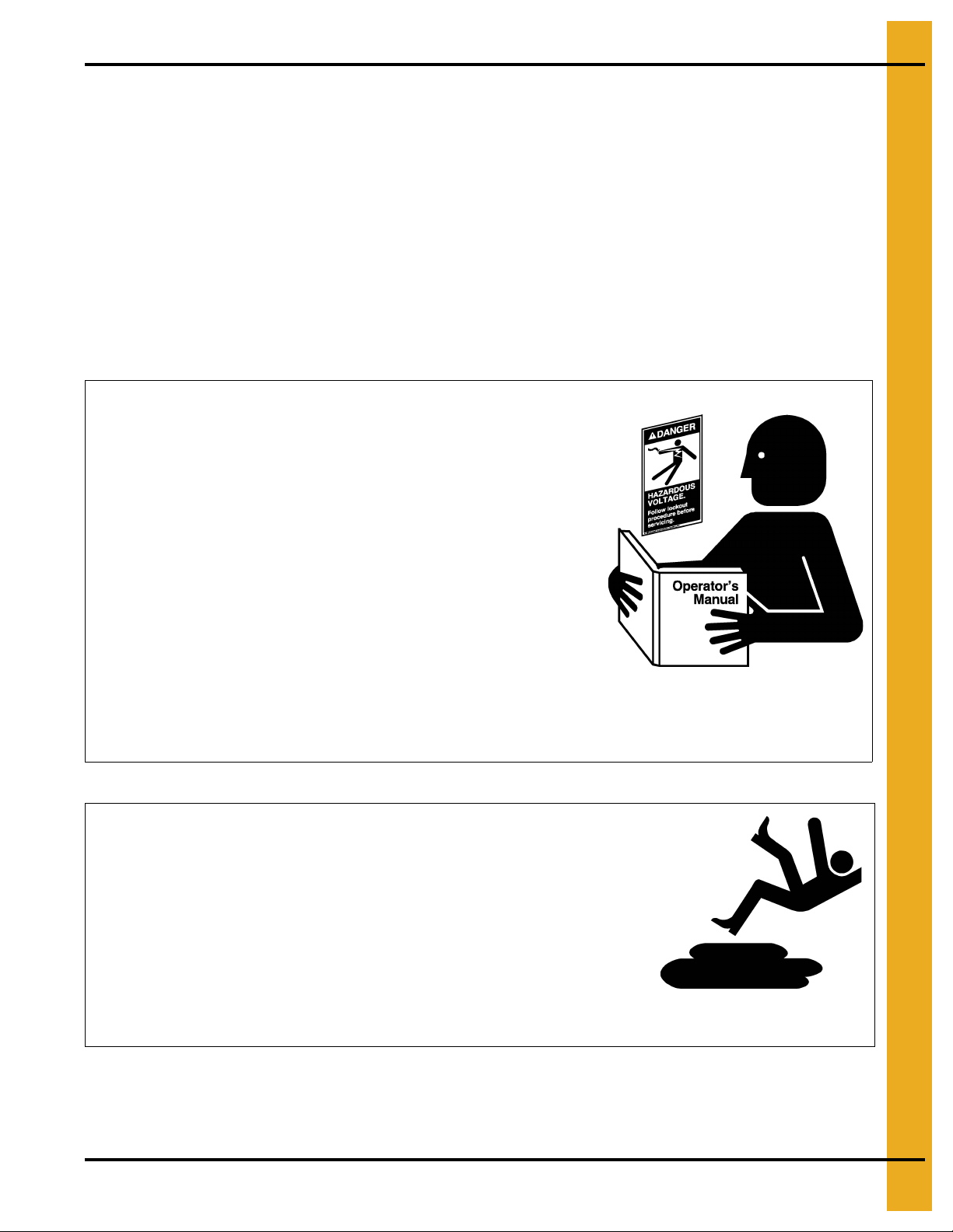
Follow Safety Instructions
Carefully read all safety messages in this manual and
safety signs on your machine. Keep signs in good
condition. Replace missing or damaged safety signs. Be
sure new equipment components and repair parts include
the current safety signs. Replacement safety signs are
available from the manufacturer.
Learn how to operate the machine and how to use controls
properly. Do not let anyone operate without instruction.
Keep your machinery in proper working condition.
Unauthorized modifications to the machine may impair
the function and/or safety and affect machine life.
If you do not understand any part of this manual or need
assistance, contact your dealer.
Read and Understand Manual
Practice Safe Maintenance
Understand service procedures before doing work. Keep area
clean and dry.
Never lubricate, service, or adjust machine while it is in operation.
Keep hands, feet, and clothing away from rotating parts.
Keep all parts in good condition and properly installed. Fix
damage immediately . Replace worn or broken p arts. Remove any
built-up grease, oil, and debris.
Maintain Equipment
and Work Area
Safety Instructions
Our foremost concern is your safety and the safety of others associated with this equipment. We want to
keep you as a customer. This manual is to help you understand safe operating procedures and some
problems that may be encountered by the operator and other personnel.
As owner and/or operator, it is your responsibility to know what requirements, hazards, and precautions
exist, and to inform all personnel associated with the equipment or in the area. Safety precautions may be
required from the personnel. Avoid any alterations to the equipment. Such alterations may produce a very
dangerous situation where SERIOUS INJURY or DEATH may occur.
This equipment shall be installed in accordance with the current installation codes and applicable
regulations, which should be carefully followed in all cases. Authorities having jurisdiction should be
consulted before installations are made.
PNEG-1833 75' Dura-Lok Plank and Support Manual 7
Page 8
2. Safety
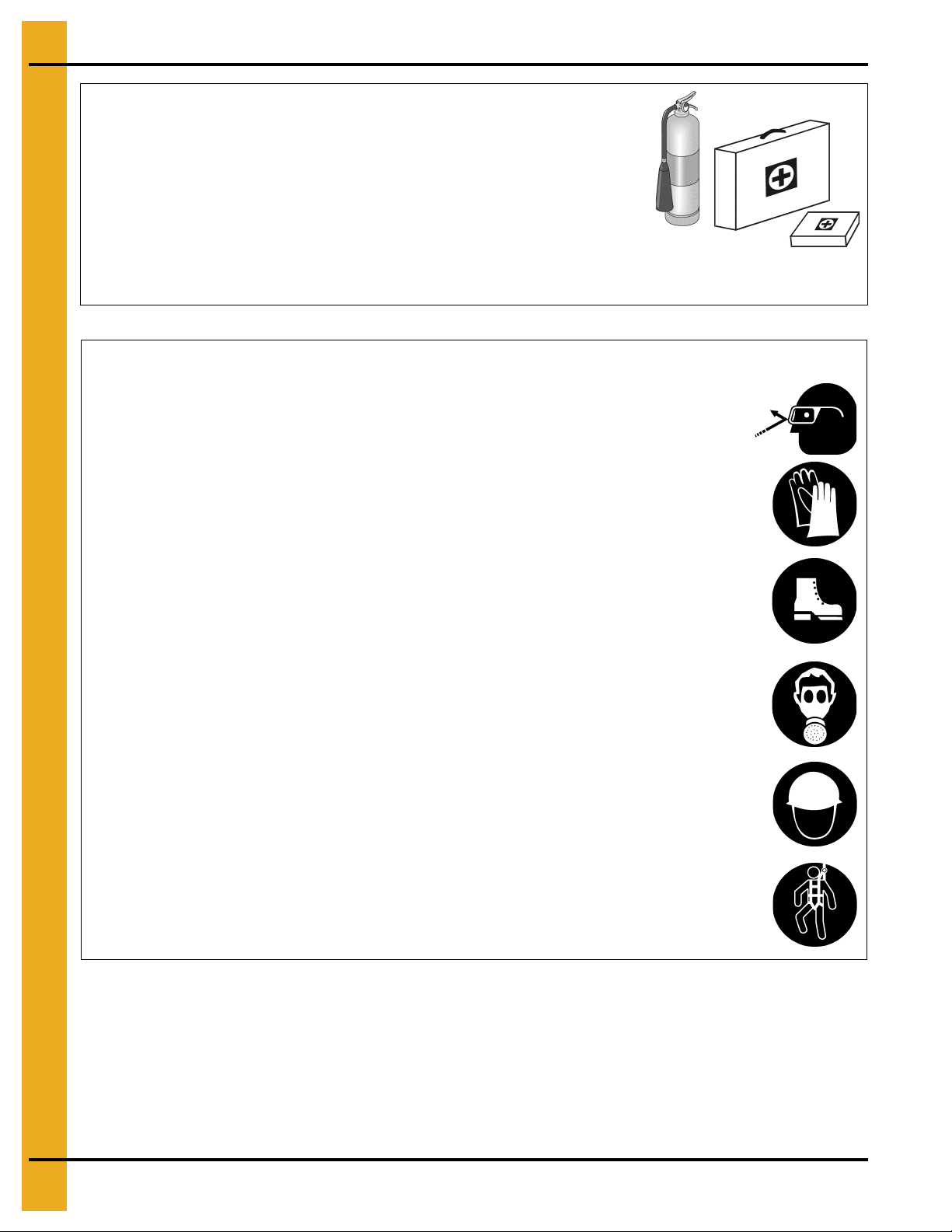
Prepare for Emergencies
Be prepared if fire starts.
Keep a first aid kit and fire extinguisher handy.
Keep emergency numbers for doctors, ambulance service,
hospital, and fire department near your telephone.
Keep Emergency Equipment
Quickly Accessible
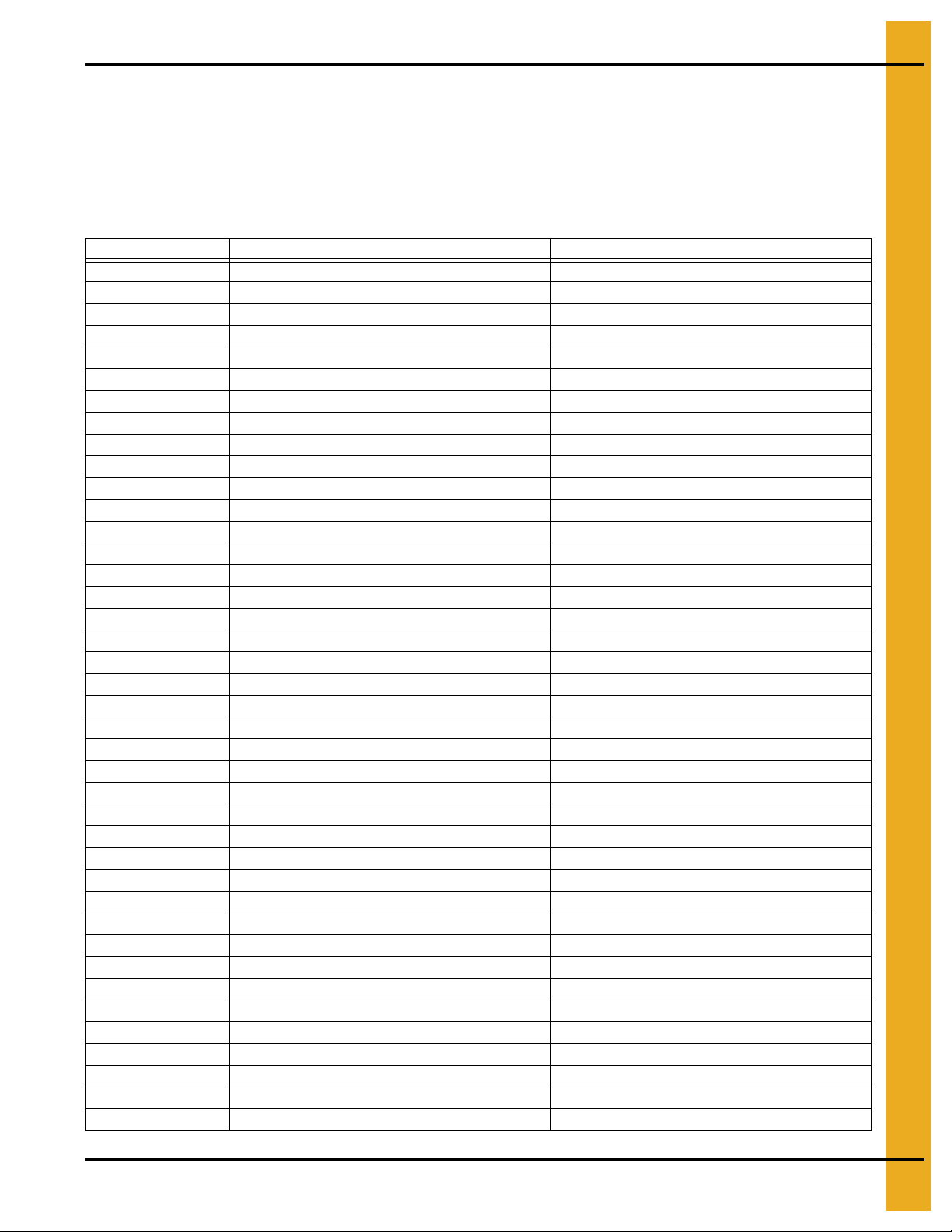
Wear Protective Clothing
Wear close-fitting clothing and safety equipment appropriate
to the job.
Remove all jewelry.
Tie long hair up and back.
Wear safety glasses at all times to protect eyes from debris.
Wear gloves to protect your hands from sharp edges on
plastic or steel parts.
Wear steel-toed boots to help protect your feet from falling
debris. Tuck in any loose or dangling shoestrings.
A respirator may be needed to prevent breathing potentially
toxic fumes and dust.
Wear a hard hat to help protect your head.
Wear appropriate fall protection equipment when working at
elevations greater than six feet (6').
Eye Protection
Gloves
Steel-Toed Boots
Respirator
Hard Hat
Fall Protection
8 PNEG-1833 75' Dura-Lok Plank and Support Manual
Page 9
2. Safety
Safety Sign-Off Sheet
As a requirement of O.S.H.A., it is necessary for the employer to train the employee in the safe operating
and safety procedures for this equipment. This sign-off sheet is provided for your convenience and
personal record keeping. All unqualified persons are to stay out of the work area at all times. It is strongly
recommended that another qualified person who knows the shut down procedure be in the area in the
event of an emergency.
Date Employee Name Supervisor Name
PNEG-1833 75' Dura-Lok Plank and Support Manual 9
Page 10

2. Safety
Proper Storage of Grain Bin/Silo Materials Prior to Construction
Wet storage stain (rust) will develop when closely packed bundles of galvanized material, such as sidewall
and roof sheets, have moisture present. Inspect roof and sidewall bundles on arrival for any moisture. If
moisture is present, it must not be allowed to remain between the she ets. Separate the sheets or panels
immediately and wipe them down. Spray with a light oil or diesel fuel.
If possible, sidewall bundles, roof sheets and other closely packed galvanized materials should be stored
in a dry, climate controlled building. If outdoor storage is unavoidable, the materials should be stored so
that they are raised above the ground and vegetation. Any stacking an d spacing mat erials sho uld not be
corrosive or wet. Be sure to protect materials from the weather, but permit air movement around the
bundles if possible.
Storing roof bundles and sidewall sheets at a slight incline can also help minimize the presence of
moisture. Storing the bundles with the center of the dome up (like an arch) is one option for minimizing
moisture during storage. Sidewall bundles can also be stored on edge but must be secured so that they
do not fall over and cause injury.
If “white rust” or “wet storage stain” occurs, contact the manufacturer imme diately about ways to minimize
the adverse effect upon the galvanized coating.
10 PNEG-1833 75' Dura-Lok Plank and Support Manual
Page 11
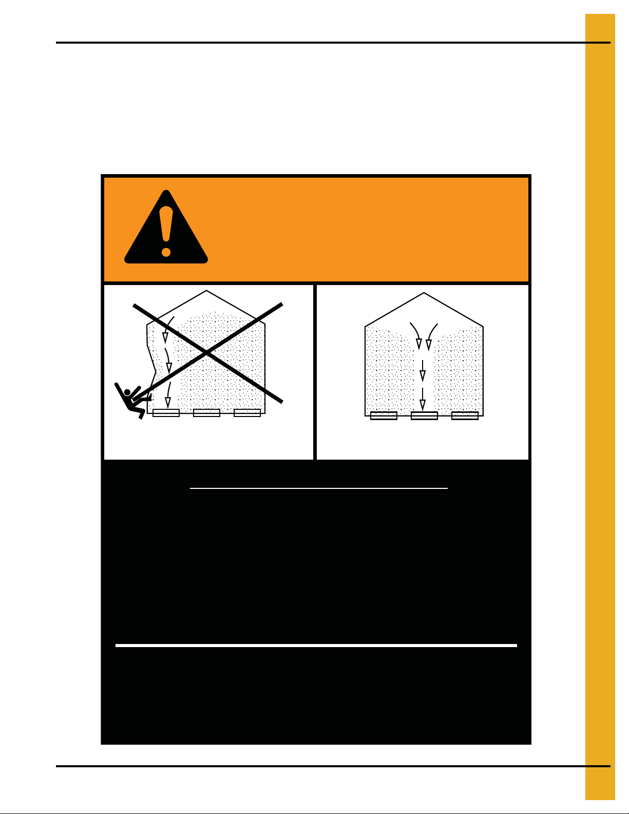
Roof Damage Warning and Disclaimer
The manufacturer does not warrant any roof damage caused by excess ive v acuum or internal
pressure from fans or other air moving systems. Adequate ventilation and/or “makeup air”
devices should be provided for all powered air handling systems. The manufacturer does not
recommend the use of downward flow systems (suction). Severe roof damage can result from
any blockage of air passages. Running fans durin g high humidity/cold weather conditions can
cause air exhaust or intake ports to freeze.
CAUTION!
3. Decals
Excessive vacuum (or pressure) may
damage roof. Use positive aeration
system. Make sure all roof vents are
open and unobstructed. Start roof
fans when supply fans are started.
Do not operate when conditions exist
that may cause roof vent icing.
DC-969
PNEG-1833 75' Dura-Lok Plank and Support Manual 11
Page 12
3. Decals
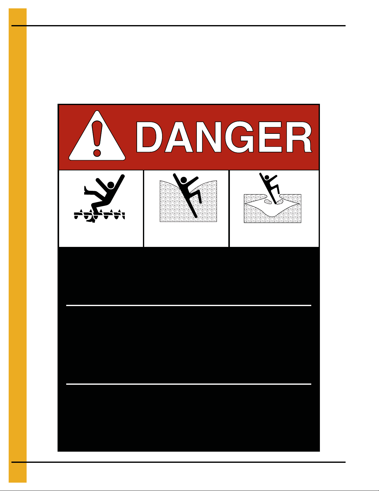
Rotating flighting will
kill or dismember.
Flowing material will
trap and suffocate.
Crusted material will
collapse and suffocate.
Keep clear of all augers.
DO NOT ENTER this bin!
Failure to heed these
warnings will result in
serious injury or death.
If you must enter the bin:
1. Shut off and lock out all power.
2. Use a safety harness and safety line.
3. Station another person outside the bin.
4. Avoid the center of the bin.
5. Wear proper breathing equipment or respirator.
DC-GBC-1A
ATTENTION: The decal shown below should be present on the outside of the door cover of the 2 ring,
24" porthole door cover and the roof manway cover. If a decal has been damaged or is missing in any of
these locations, contact the manufacturer for a free replacement decal.
GSI Decals
1004 E. Illinois St.
Assumption, IL. 62510
Phone: 1-217-226-4421
12 PNEG-1833 75' Dura-Lok Plank and Support Manual
Page 13
3. Decals
ATTENTION: The decal shown below should be present on the outside of the door cover of the 2 ring,
24" porthole door cover and the roof manway cover. If a decal has been damaged or is missing in any of
these locations, contact the manufacturer for a free replacement decal.
GSI Decals
1004 E. Illinois St.
Assumption, IL. 62510
Phone: 1-217-226-4421
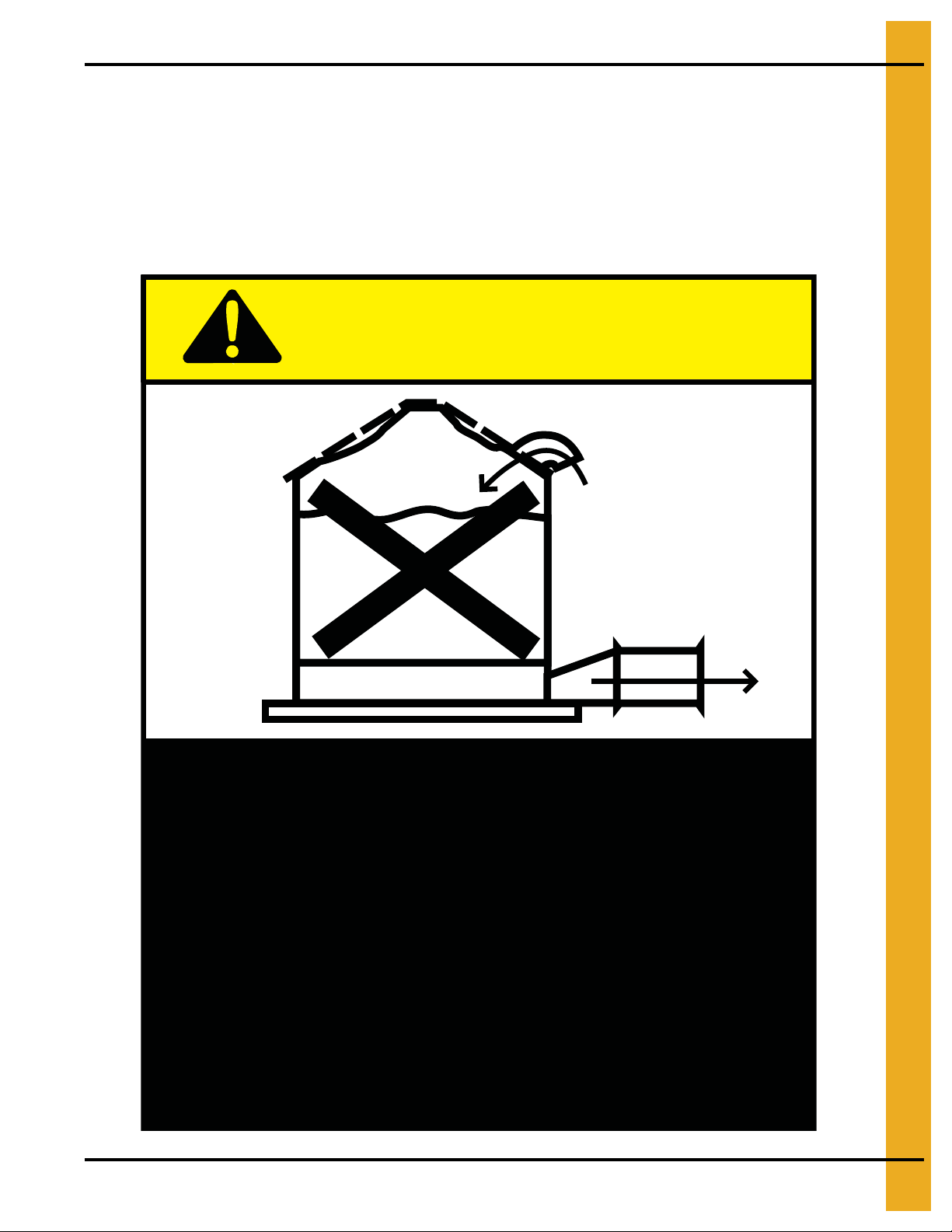
WARNING
DON’T
DO
UNLOADING INSTRUCTIONS:
1. Use CENTER FLOOR OUTLET ONLY until NO grain
remains above this outlet.
2. Side floor outlets to be used ONLY when above
condition is satisfied.
3. Lock all side floor outlets to avoid accidental
premature use.
4. See manufacturers instructions for proper use of
factory supplied sidedraw (wall) discharge systems.
Failure to heed these warnings
could result in serious injury, death,
structural damage or collapse of tank.
DC-GBC-2A
PNEG-1833 75' Dura-Lok Plank and Support Manual 13
Page 14
4. Monorail Installation
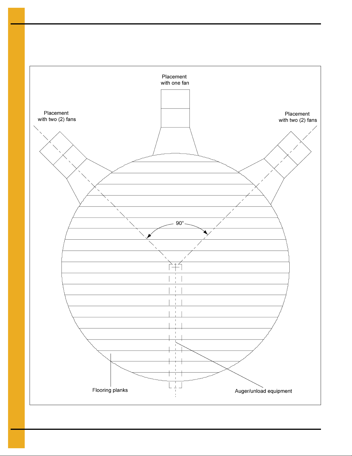
Fan Placement Diagram
For uniform air flow, place the fans in relation to the unloading tube as shown in Figure 4A. Floor planks
should be perpendicular to the unloading tube.
Figure 4A
14 PNEG-1833 75' Dura-Lok Plank and Support Manual
Page 15
4. Monorail Installation
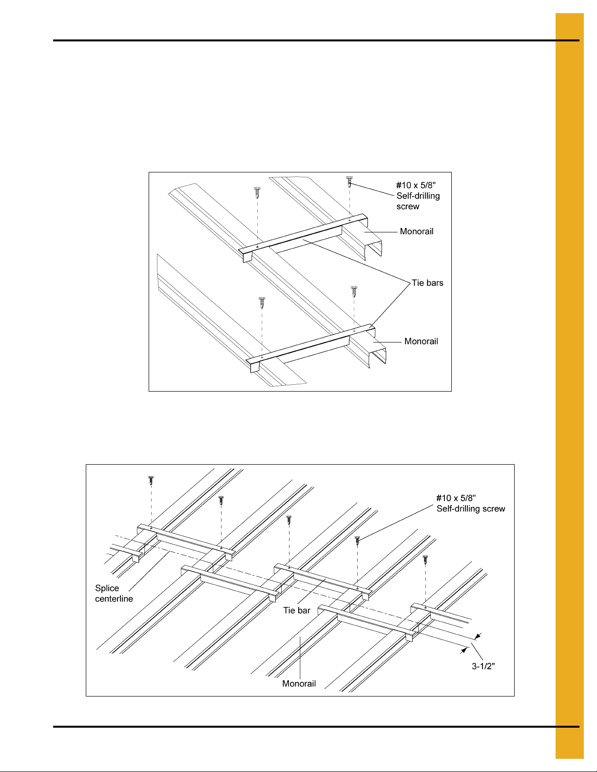
Tie Bar Detail
1. Locate the tie bars between the rails. (Spaced evenly throughout the system.)
NOTE: Tie bars are to be placed at the end of monorail, at each splice and in the middle of the rail
if it is over 16' long. (Not necessarily evenly spaced.) Rail spacing details on Pages 26-41,
detail tie bar placements in each layout.
2. A single #10 x 5/8" self-drilling screws may be used to fasten the tie bars at each end to the rails
as necessary. (See Figure 4B.)
Figure 4B Tie Bar Detail
3. Tie bars should overlap and connect each rail to the next rail. Tie bars should be located along
each side of a rail splice and around the perimeter of the bin, no more than 6" from the end of the rail.
(See Figure 4C.)
Figure 4C Tie Bar Dimension Detail
PNEG-1833 75' Dura-Lok Plank and Support Manual 15
Page 16

4. Monorail Installation
Tie Strap Detail
1. Tie straps should be used when a tie bar cannot be used to connect rails together due to special
spacing of monorail. Tie strap should be connected to all three (3) rails using self-drilling screws.
(See Figure 4D.)
2. Tie straps are to be located in the same places as a tie bar would be used.
NOTE: Some tie straps will be used to support center well and intermediate well assembly.
(See Figure 5F on Page 24 and Figure 5G on Page 25.)
Figure 4D Strap Detail
16 PNEG-1833 75' Dura-Lok Plank and Support Manual
Page 17

4. Monorail Installation
See chart on Page 18.
Spacing depends on
eave height.
Assembling Legs to Rail
1. Place two (2) corners of the monorail leg into the rails as shown.
2. By twisting the leg it will spread the rail enough to get the other corners inside.
3. The leg can then be pushed down into the rail until the tabs lock it into place. (See Figure 4E.)
PNEG-1833 75' Dura-Lok Plank and Support Manual 17
Figure 4E Assembly Leg Rail
Page 18

4. Monorail Installation
Monorail “Rail and Leg Spacing”/“Full Floor Leg Quantity” for 75' Bin Diameter
4.00"
Ring
3 4 11 26 See Page 41 22 1469
46 16 26See Page 41 20 1608
5 8 22 22 See Page 38 20 1883
710 27 22See Page 38 19 1976
9 12 33 20 See Page 37 18 2202
10 14 38 20 See Page 37 18 2202
11 16 43 18 See Page 34 18 2379
13 18 48 18 See Page 34 17 2512
14 20 54 18 See Page 34 16 2662
16 22 59 17 See Page 33 16 2703
17 24 64 17 See Page 33 16 2703
19 26 70 16 See Page 30 16 2986
20 28 75 16 See Page 30 15 3174
22 30 81 15 See Page 29 15 3079
2.66"
Ring
Eave Height (ft.) Rail Spacing
Reference
Page
Leg Spacing Leg Qty
23 32 86 15 See Page 29 15 3079
25 34 92 15 See Page 29 15 3079
27 37 100 14 See Page 26 15 3519
18 PNEG-1833 75' Dura-Lok Plank and Support Manual
Page 19

4. Monorail Installation
Outer Perimeter Rail Details
3' Sections of monorail should be placed around the perimeter of the bin. Monorail legs for perimeter rails
should be spaced 16" apart on center. (See Figure 4F.)
Figure 4F
PNEG-1833 75' Dura-Lok Plank and Support Manual 19
Page 20

4. Monorail Installation
Splicing Rails
1. A leg must be centered at each rail splice.
2. The closest leg may be moved a few inches over to center it under the splice. If more than 3" of
movement is required to center the leg under the splice, add an additional leg.
3. Fasten the rail to the leg with two (2) #10 self-drilling screws (splice locations o nly). (See Figure 4G.)
Figure 4G
20 PNEG-1833 75' Dura-Lok Plank and Support Manual
Page 21

5. Flooring - Planks
Two (2) splices loca ted at each splice location.
(See Figure 5B on Page 22.)
Floor Splice Details
Some of the floor planks will need to be spliced together. (See Figure 5F on Page 24 and plank layout
on Page 45 and plank length chart on Page 46.) Install plank length A first, then in stall the corresponding
plank length B. Continue until floor is complete. Center and install two (2) splices (PCL-7009) at each plank
splice location using self-drilling screws. Use eight (8) screws at the end of the splice for each plank,
four (4) on each side. (See Figure 5A below and Figure 5B on Page 22.)
PNEG-1833 75' Dura-Lok Plank and Support Manual 21
Figure 5A Floor Splice Layout
Page 22

5. Flooring - Planks
Figure 5B Splice Assembly View
Flashing Installation
Figure 5C
Formed Flashing Installation
If bin sweep auger is to be used, overlap flashing such that rotation (usually clockwise) of the sweep will
climb up on the next flashing section. (See detail C in Figure 5C.) This will prevent the rotating/slipping
outer wheel of the sweep from catching on the flashing edges.
After the floor is in place, lay the flashing pieces on top of the floor place over the 1-1/4" bin bolts.
See Figure 5D and Figure 5E on Page 23 to determine the correct sequence for placing the nuts and
washers. Finger tighten the nuts. While holding flashing flat, fasten the flashing to the floor with sheet
metal screws. Now tighten flashing nuts.
22 PNEG-1833 75' Dura-Lok Plank and Support Manual
Page 23

Flashing Installation (Continued)
Figure 5D 2.66" Corrugation
5. Flooring - Planks
Figure 5E 4.00" Corrugation
PNEG-1833 75' Dura-Lok Plank and Support Manual 23
Page 24

5. Flooring - Planks
Center Well Assembly Details
Figure 5F 75' Diameter Bin Center Well Position
24 PNEG-1833 75' Dura-Lok Plank and Support Manual
Page 25

Intermediate Well Assembly Details
5. Flooring - Planks
Figure 5G 75' Diameter Bin Intermediate Well Position
PNEG-1833 75' Dura-Lok Plank and Support Manual 25
Page 26

6. Layouts
NOTE: This depicts monorail spacings only. Leg spacing is dependant
on eave height. See Page 18 for leg and rail spacing chart.
Tie bar (See Page 15 for
installation detail.)
Tie strap (See Page 16
for installation detail.)
75'-14" Rail Spacing Layout
Figure 6A 75' Diameter 14" Rail Spacing
26 PNEG-1833 75' Dura-Lok Plank and Support Manual
Page 27

75'-14" Monorail Spacing Layout
NOTE: Seventy seven (77) total outer perimeter 3'
monorail pieces. See Page 17 for leg support details.
Bill of Materials
Part # Length Qty
A-22MONO 264 86
A-21.75MONO 261 4
A-21.67MONO 260 4
A-21.08MONO 253 4
A-20.42MONO 245 4
A-19.9MONO 239 4
A-19.67MONO 236 4
A-18.8MONO 226 4
A-18.67MONO 224 2
A-18MONO 216 4
A-17.9MONO 215 4
A-17MONO 204 4
A-15.91MONO 191 4
A-15.75MONO 189 4
A-14.9MONO 179 4
A-14.83MONO 178 8
A-14.75MONO 177 4
A-14.67MONO 176 4
A-14.5MONO 174 4
A-14.4MONO 172 4
A-14.08MONO 169 4
A-13.9MONO 166 4
A-13.58MONO 163 8
A-13.5MONO 162 4
A-13.3MONO 160 4
A-13.2MONO 158 4
A-13MONO 156 4
A-12.8MONO 153 4
A-12.3MONO 148 4
A-12.17MONO 146 4
A-11.83MONO 142 4
A-11.8MONO 141 2
A-11.3MONO 136 4
A-3MONO 36 103
75' Diameter 14" Spacing
Measurement in Inches
Rail # Section 1 Section 2 Section 3 Section 4
1 179 264 264 179
2 178 264 264 178
3 177 264 264 177
4 176 264 264 176
5 174 264 264 174
6 172 264 264 172
7 169 264 264 169
8 166 264 264 166
9 163 264 264 163
* 10 162 264 264 162
* 11 160 264 264 160
12 158 264 264 158
13 153 264 264 153
14 148 264 264 148
15 142 264 264 142
16 136 264 264 136
17 261 264 261 0
18 253 264 253 0
19 245 264 245 0
20 236 264 236 0
21 226 264 226 0
22 215 264 215 0
23 204 264 204 0
24 191 264 191 0
25 178 264 178 0
26 163 264 163 0
27 146 264 146 0
28 260 260 0 0
29 239 239 0 0
30 216 216 0 0
31 189 189 0 0
32 156 156 0 0
33 224 0 0 0
34 141 0 0 0
22.86 m Diameter 35.56 cm Spacing
Measurement in Centimeters
Rail # Section 1 Section 2 Section 3 Section 4
1 454.66 670.56 670.56 454.66
2 452.12 670.56 670.56 452.12
3 449.58 670.56 670.56 449.58
4 447.04 670.56 670.56 447.04
5 441.96 670.56 670.56 441.96
6 436.88 670.56 670.56 436.88
7 429.26 670.56 670.56 429.26
8 421.64 670.56 670.56 421.64
9 414.02 670.56 670.56 414.02
* 10 411.48 670.56 670.56 411.48
* 11 406.4 670.56 670.56 406.4
12 401.32 670.56 670.56 401.32
13 388.62 670.56 670.56 388.62
14 375.92 670.56 670.56 375.92
15 360.68 670.56 670.56 360.68
16 345.44 670.56 670.56 345.44
17 662.94 670.56 662.94 0
18 642.62 670.56 642.62 0
19 622.3 670.56 622.3 0
20 599.44 670.56 599.44 0
21 574.04 670.56 574.04 0
22 546.1 670.56 546.1 0
23 518.16 670.56 518.16 0
24 485.14 670.56 485.14 0
25 452.12 670.56 452.12 0
26 414.02 670.56 414.02 0
27 370.84 670.56 370.84 0
28 660.4 660.4 0 0
29 607.06 607.06 0 0
30 548.64 548.64 0 0
31 480.06 480.06 0 0
32 396.24 396.24 0 0
33 548.96 0 0 0
34 358.14 0 0 0
Part # Description Qty
FL-404-14 14" Monorail Tie Bar 380
S-280 #10-16 x 5/8" Zinc Self-Drilling Screw 1270
FL-7411 Monorail Strap 1-1/2" x 30" x 0.061" 110
* NOTE: This special monorail run is used to support
the floor plank at the split.
PNEG-1833 75' Dura-Lok Plank and Support Manual 27
Figure 6B 75' Diameter Bin with 14" Monorail Spacing
6. Layouts
Page 28

6. Layouts
Part # Description Qty
FL-404-15 15" Monorail Tie Bar 350
S-280 #10-16 x 5/8" Zinc Self-Drilling Screw 1200
FL-7411 Monorail Strap 1-1/2" x 30" x 0.061" 70
NOTE: Seventy seven (77) total outer perimeter 3' monorail
pieces. See Page 17 for leg support details.
Bill of Materials
Part # Length Qty
A-22MONO 264 74
A-21.75MONO 261 4
A-21.08MONO 253 4
A-20.42MONO 245 4
A-20.3MONO 244 4
A-19.5MONO 234 4
A-18.67MONO 224 4
A-18.42MONO 221 4
A-18.33MONO 220 2
A-17.66MONO 212 4
A-16.58MONO 199 4
A-16.08MONO 193 4
A-15.41MONO 185 4
A-14.9MONO 179 4
A-14.83MONO 178 4
A-14.75MONO 177 4
A-14.58MONO 175 4
A-14.42MONO 173 4
A-14.25MONO 171 4
A-14.17MONO 170 4
A-14MONO 168 4
A-13.7MONO 164 4
A-13.3MONO 160 4
A-13.2MONO 158 4
A-12.9MONO 155 4
A-12.8MONO 153 4
A-12.42MONO 149 4
A-11.92MONO 143 4
A-11.42MONO 137 2
A-1 1 .3MONO 136 4
A-11.17MONO 134 4
A-3MONO 36 103
75' Diameter 15" Spacing
Measurement in Inches
Rail # Section 1 Section 2 Section 3 Section 4
1 179 264 264 179
2 178 264 264 178
3 177 264 264 177
4 175 264 264 175
5 173 264 264 173
6 171 264 264 171
7 168 264 264 168
8 164 264 264 164
9 160 264 264 160
10 155 264 264 155
11 149 264 264 149
12 143 264 264 143
13 136 264 264 136
14 261 264 261 0
15 253 264 253 0
16 244 264 244 0
17 234 264 234 0
18 224 264 224 0
19 212 264 212 0
20 199 264 199 0
21 185 264 185 0
22 170 264 170 0
23 153 264 153 0
24 134 264 134 0
25 245 245 0 0
26 221 221 0 0
27 193 193 0 0
28 158 158 0 0
29 220 0 0 0
30 137 0 0 0
22.86 m Diameter 38.10 cm Spacing
Measurement in Centimeters
Rail # Section 1 Section 2 Section 3 Section 4
1 454.66 670.56 670.56 454.66
2 452.12 670.56 670.56 452.12
3 449.58 670.56 670.56 449.58
4 444.5 670.56 670.56 444.5
5 439.42 670.56 670.56 439.42
6 434.34 670.56 670.56 434.34
7 426.72 670.56 670.56 426.72
8 416.56 670.56 670.56 416.56
9 406.4 670.56 670.56 406.4
10 393.7 670.56 670.56 393.7
11 378.46 670.56 670.56 378.46
12 363.22 670.56 670.56 363.22
13 345.44 670.56 670.56 345.44
14 662.94 670.56 662.94 0
15 642.62 670.56 642.62 0
16 619.76 670.56 619.76 0
17 594.36 670.56 594.36 0
18 568.96 670.56 568.96 0
19 538.48 670.56 538.48 0
20 505.46 670.56 505.46 0
21 469.9 670.56 469.9 0
22 431.8 670.56 431.8 0
23 388.62 670.56 388.62 0
24 340.36 340.36 340.36 0
25 622.3 622.3 0 0
26 561.34 561.34 0 0
27 490.22 490.22 0 0
28 401.32 401.32 0 0
29 558.8 0 0 0
30 347.98 0 0 0
75'-15" Monorail Spacing Layout
28 PNEG-1833 75' Dura-Lok Plank and Support Manual
Figure 6C 75' Diameter Bin with 15" Monorail Spacing
Page 29

75'-15" Rail Spacing Layout
NOTE: This depicts monorail spacings only. Leg spacing is dependant
on eave height. See Page 18 for leg and rail spacing chart.
Tie bar (See Page 15 for
installation detail.)
6. Layouts
Figure 6D 75' Diameter 15" Rail Spacing
PNEG-1833 75' Dura-Lok Plank and Support Manual 29
Page 30

6. Layouts
Tie bar (See Page 15
for installation detail.)
Tie strap (See Page 16
for installation detail.)
NOTE: This depicts monorail spacings only. Leg spacing is dependant
on eave height. See Page 18 for leg and rail spacing chart.
75'-16" Rail Spacing Layout
Figure 6E 75' Diameter 16" Rail Spacing
30 PNEG-1833 75' Dura-Lok Plank and Support Manual
Page 31

75'-16" Monorail Spacing Layout
Part # Description Qty
FL-404-16 16" Monorail Tie Bar 330
FL-7411 Monorail Strap 1-1/2" x 30" x 0.061" 120
S-280 #10-16 x 5/8" Zinc Self-Drilling Screw 1120
Bill of Materials
Part # Length Qty
A-22MONO 264 76
A-21.92MONO 263 4
A-21.33MONO 256 4
A-21.16MONO 254 4
A-20.67MONO 248 2
A-20.3MONO 244 4
A-19.5MONO 234 4
A-19.3MONO 232 4
A-18.63MONO 223 4
A-17.5MONO 210 4
A-16.9MONO 203 4
A-16.3MONO 196 4
A-15.08MONO 181 4
A-14.9MONO 179 4
A-14.83MONO 178 4
A-14.75MONO 177 4
A-14.58MONO 175 4
A-14.42MONO 173 4
A-14.17MONO 170 4
A-14.08MONO 169 4
A-13.9MONO 166 4
A-13.7MONO 164 4
A-13.58MONO 163 4
A-13.5MONO 162 4
A-13.3MONO 160 4
A-13.2MONO 158 2
A-13.1MONO 157 4
A-12.58MONO 151 4
A-12.1MONO 145 8
A-1 1 .5MONO 138 4
A-4.25MONO 51 4
A-3MONO 36 103
75' Diameter 16" Spacing
Measurement in Inches
Rail # Section 1 Section 2 Section 3 Section 4
1 179 264 264 179
2 178 264 264 178
* 2A 51 0 0 51
3 177 264 264 177
4 175 264 264 175
5 173 264 264 173
6 170 264 264 170
7 166 264 264 166
8 163 264 264 163
* 9 162 264 264 162
* 10 160 264 264 160
11 157 264 264 157
12 151 264 264 151
13 145 264 264 145
14 138 264 264 138
15 263 264 263 0
16 254 264 254 0
17 244 264 244 0
18 234 264 234 0
19 223 264 223 0
20 210 264 210 0
21 196 264 196 0
22 181 264 181 0
23 164 264 164 0
24 145 264 145 0
25 256 256 0 0
26 232 232 0 0
27 203 203 0 0
28 169 169 0 0
29 248 0 0 0
30 158 0 0 0
21.95 m Diameter 40.64 cm Spacing
Measurement in Centimeters
Rail # Section 1 Section 2 Section 3 Section 4
1 454.66 670.56 670.56 454.66
2 452.12 670.56 670.56 452.12
* 2A 129.54 0 0 129.54
3 449.58 670.56 670.56 449.58
4 444.5 670.56 670.56 444.5
5 439.42 670.56 670.56 439.42
6 431.8 670.56 670.56 431.8
7 421.64 670.56 670.56 421.64
8 414.02 670.56 670.56 414.02
* 9 411.48 670.56 670.56 411.48
* 10 406.4 670.56 670.56 406.4
11 398.78 670.56 670.56 398.78
12 383.54 670.56 670.56 383.54
13 368.3 670.56 670.56 368.3
14 350.52 670.56 670.56 350.52
15 668.02 670.56 668.02 0
16 645.16 670.56 645.16 0
17 619.76 670.56 619.76 0
18 594.36 670.56 594.36 0
19 566.42 670.56 566.42 0
20 533.4 670.56 533.4 0
21 497.84 670.56 497.84 0
22 459.74 670.56 459.74 0
23 416.56 670.56 416.56 0
24 368.3 670.56 368.3 0
25 650.24 650.24 0 0
26 589.28 589.28 0 0
27 515.62 515.62 0 0
28 429.26 429.26 0 0
29 629.92 0 0 0
30 401.32 0 0 0
NOTE: Seventy seven (77) total outer perimeter 3' monorail
pieces. See Page 17 for leg support details.
* NOTE: This special monorail run is used to support the floor
plank at the split.
PNEG-1833 75' Dura-Lok Plank and Support Manual 31
6. Layouts
Figure 6F 75' Diameter Bin with 16" Monorail Spacing
Page 32

6. Layouts
Part # Description Qty
FL-404-17 17" Monorail Tie Bar 310
FL-7411 Monorail Strap 1-1/2" x 30" x 0.061" 110
S-280 #10-16 x 5/8" Zinc Self-Drilling Screw 1060
Bill of Materials
Part # Length Qty
A-22MONO 264 70
A-21.33MONO 256 4
A-20.67MONO 248 4
A-20.5MONO 246 4
A-19.58MONO 235 4
A-18.63MONO 223 4
A-18.42MONO 221 4
A-17.42MONO 209 4
A-16.3MONO 196 2
A-16.25MONO 195 4
A-15.7MONO 188 4
A-14.9MONO 179 8
A-14.83MONO 178 4
A-14.75MONO 177 4
A-14.58MONO 175 4
A-14.4MONO 172 4
A-14.08MONO 169 4
A-13.7MONO 164 4
A-13.58MONO 163 4
A-13.3MONO 160 8
A-12.83MONO 154 4
A-12.3MONO 148 4
A-12.17MONO 146 4
A-1 1 .8MONO 141 4
A-11.58MONO 139 4
A-11.08MONO 133 4
A-4.25MONO 51 4
A-3MONO 36 103
75' Diameter 17" Spacing
Measurement in Inches
Rail # Section 1 Section 2 Section 3 Section 4
1 179 264 264 179
2 178 264 264 178
* 2A 51 0 0 51
3 177 264 264 177
4 175 264 264 175
5 172 264 264 172
6 169 264 264 169
7 164 264 264 164
* 8 163 264 264 163
9 160 264 264 160
10 154 264 264 154
11 148 264 264 148
12 141 264 264 141
13 133 264 264 133
14 256 264 256 0
15 246 264 246 0
16 235 264 235 0
17 223 264 223 0
18 209 264 209 0
19 195 264 195 0
20 179 264 179 0
21 160 264 160 0
22 139 264 139 0
23 248 248 0 0
24 221 221 0 0
25 188 188 0 0
26 146 146 0 0
27 196 0 0 0
21.95 m Diameter 43.18 cm Spacing
Measurement in Centimeters
Rail # Section 1 Section 2 Section 3 Section 4
1 454.66 670.56 670.56 454.66
2 452.12 670.56 670.56 452.12
* 2A 129.54 0 0 129.54
3 449.58 670.56 670.56 449.58
4 444.5 670.56 670.56 444.5
5 436.88 670.56 670.56 436.88
6 429.26 670.56 670.56 429.26
7 416.56 670.56 670.56 416.56
* 8 414.02 670.56 670.56 414.02
9 406.4 670.56 670.56 406.4
10 391.16 670.56 670.56 391.16
11 375.92 670.56 670.56 375.92
12 358.14 670.56 670.56 358.14
13 337.82 670.56 670.56 337.82
14 650.24 670.56 650.24 0
15 624.84 670.56 624.84 0
16 596.9 670.56 596.9 0
17 566.42 670.56 566.42 0
18 530.86 670.56 530.86 0
19 495.3 670.56 495.3 0
20 454.66 670.56 454.66 0
21 406.4 670.56 406.4 0
22 353.06 670.56 353.06 0
23 629.92 629.92 0 0
24 561.34 561.34 0 0
25 477.52 477.52 0 0
26 370.84 370.84 0 0
27 497.84 0 0 0
NOTE: Seventy seven (77) total outer perimeter 3' monorail
pieces. See Page 17 for leg support details.
* NOTE: This special monorail run is used to support the
floor plank at the split.
75'-17" Monorail Spacing Layout
32 PNEG-1833 75' Dura-Lok Plank and Support Manual
Figure 6G 75' Diameter Bin with 17" Monorail Spacing
Page 33

75'-17" Rail Spacing Layout
Tie bar (See Page 15 for
installation detail.)
Tie strap (See Page 16
for installation detail.)
NOTE: This depicts monorail spacings only. Leg spacing is dependant
on eave height. See Page 18 for leg and rail spacing chart.
6. Layouts
Figure 6H 75' Diameter 17" Rail Spacing
PNEG-1833 75' Dura-Lok Plank and Support Manual 33
Page 34

6. Layouts
Tie strap (See Page 16
for installation detail.)
NOTE: This depicts monorail spacings only. Leg spacing is dependant
on eave height. See Page 18 for leg and rail spacing chart.
Tie bar (See Page 15 for
installation detail.)
75'-18" Rail Spacing Layout
Figure 6I 75' Diameter 18" Rail Spacing
34 PNEG-1833 75' Dura-Lok Plank and Support Manual
Page 35

75'-18" Monorail Spacing Layout
Part # Description Qty
FL-404-18 18" Monorail Tie Bar 300
FL-7411 Monorail Strap 1-1/2" x 30" x 0.061" 120
S-280 #10-16 x 5/8" Zinc Self-Drilling Screw 1020
Bill of Materials
Part # Length Qty
A-22MONO 264 70
A-21.58MONO 259 4
A-21.16MONO 254 2
A-20.75MONO 249 4
A-20.25MONO 243 4
A-19.75MONO 237 4
A-18.75MONO 225 4
A-17.66MONO 212 4
A-17.58MONO 211 4
A-16.25MONO 195 4
A-14.9MONO 179 4
A-14.83MONO 178 8
A-14.67MONO 176 8
A-14.5MONO 174 4
A-14.25MONO 171 4
A-13.91MONO 167 4
A-13.75MONO 165 2
A-13.7MONO 164 4
A-13.58MONO 163 4
A-13.3MONO 160 4
A-13.2MONO 158 4
A-13.1MONO 157 4
A-12.58MONO 151 4
A-12MONO 144 4
A-11.3MONO 136 8
A-4.25MONO 51 4
A-3MONO 36 103
75' Diameter 18" Spacing
Measurement in Inches
Rail # Section 1 Section 2 Section 3 Section 4
1 179 264 264 179
2 178 264 264 178
* 2A 51 0 0 51
3 176 264 264 176
4 174 264 264 174
5 171 264 264 171
6 167 2 264 167
7 164 264 264 164
* 8 163 264 264 163
* 9 160 264 264 160
10 157 264 264 157
11 151 264 264 151
12 144 264 264 144
13 136 264 264 136
14 259 264 259 0
15 249 264 249 0
16 237 264 237 0
17 225 264 225 0
18 211 264 211 0
19 195 264 195 0
20 178 262 178 0
21 158 264 158 0
22 136 264 136 0
23 243 243 0 0
24 212 212 0 0
25 176 176 0 0
26 254 0 0 0
27 165 0 0 0
22.86 m Diameter 45.72 cm Spacing
Measurement in Centimeters
Rail # Section 1 Section 2 Section 3 Section 4
1 454.66 670.56 670.56 454.66
2 452.12 670.56 670.56 452.12
* 2A 129.54 0 0 129.54
3 447.04 670.56 670.56 447.04
4 441.96 670.56 670.56 441.96
5 434.34 670.56 670.56 434.34
6 424.18 670.56 670.56 424.18
7 416.56 670.56 670.56 416.56
* 8 414.02 670.56 670.56 414.02
* 9 406.4 670.56 670.56 406.4
10 398.78 670.56 670.56 398.78
11 383.54 670.56 670.56 383.54
12 365.76 670.56 670.56 365.76
13 345.44 670.56 670.56 345.44
14 657.86 670.56 657.86 0
15 632.46 670.56 632.46 0
16 601.98 670.56 601.98 0
17 571.5 670.56 571.5 0
18 535.94 670.56 535.94 0
19 495.3 670.56 495.3 0
20 452.12 670.56 452.12 0
21 401.32 670.56 401.32 0
22 345.44 670.56 345.44 0
23 617.22 617.22 0 0
24 538.48 538.48 0 0
25 447.04 447.04 0 0
26 645.16 0 0 0
27 419.1 0 0 0
NOTE: Seventy seven (77) total outer perimeter 3' monorail
pieces. See Page 17 for leg support details.
* NOTE: This special monorail run is used to support the
floor plank at the split.
PNEG-1833 75' Dura-Lok Plank and Support Manual 35
6. Layouts
Figure 6J 75' Diameter Bin with 18" Monorail Spacing
Page 36

6. Layouts
Part # Description Qty
FL-404-1 20" Monorail Tie Bar 270
FL-7411 Monorail Strap 1-1/2" x 30" x 0.061" 120
S-280 #10-16 x 5/8" Zinc Self-Drilling Screw 940
Bill of Materials
Part # Length Qty
A-22MONO 264 64
A-21.42MONO 257 4
A-20.5MONO 246 4
A-20.08MONO 241 4
A-19.3MONO 232 4
A-18.5MONO 222 2
A-18.2MONO 218 4
A-17.25MONO 207 4
A-16.8MONO 202 4
A-15.25MONO 183 4
A-14.9MONO 179 4
A-14.83MONO 178 4
A-14.67MONO 176 4
A-14.42MONO 173 4
A-14.08MONO 169 4
A-13.7MONO 164 8
A-13.58MONO 163 4
A-13.42MONO 161 4
A-13.3MONO 160 4
A-13.25MONO 159 4
A-12.7MONO 152 4
A-12MONO 144 4
A-11.42MONO 137 4
A-11.25MONO 135 4
A-4.25MONO 51 4
A-3MONO 36 103
75' Diameter 20" Spacing
Measurement in Inches
Rail # Section 1 Section 2 Section 3 Section 4
1 179 264 264 179
2 178 264 264 178
* 2 51 0 0 51
3 176 264 264 176
4 173 264 264 173
5 169 264 264 169
6 164 264 264 164
* 7 163 264 264 163
* 8 160 264 264 160
9 159 264 264 159
10 152 264 264 152
11 144 264 264 144
12 135 264 264 135
13 257 264 257 0
14 246 264 246 0
15 232 264 232 0
16 218 264 218 0
17 202 264 202 0
18 183 264 183 0
19 161 264 161 0
20 137 264 137 0
21 241 241 0 0
22 207 207 0 0
23 164 164 0 0
24 222 0 0 0
21.95 m Diameter 50.80 cm Spacing
Measurement in Centimeters
Rail # Section 1 Section 2 Section 3 Section 4
1 454.66 670.56 670.56 454.66
2 452.12 670.56 670.56 452.12
* 2 129.54 0 0 129.54
3 447.04 670.56 670.56 447.04
4 439.42 670.56 670.56 439.42
5 429.26 670.56 670.56 429.26
6 416.56 670.56 670.56 416.56
* 7 414.02 670.56 670.56 414.02
* 8 406.4 670.56 670.56 406.4
9 403.86 670.56 670.56 403.86
10 386.08 670.56 670.56 386.08
11 365.76 670.56 670.56 365.76
12 342.9 670.56 670.56 342.9
13 652.78 670.56 652.78 0
14 624.84 670.56 624.84 0
15 589.28 670.56 589.28 0
16 553.72 670.56 553.72 0
17 513.08 670.56 513.08 0
18 464.82 670.56 464.82 0
19 408.94 670.56 408.94 0
20 347.98 670.56 347.98 0
21 612.14 612.14 0 0
22 525.78 525.78 0 0
23 416.56 416.56 0 0
24 563.88 0 0 0
NOTE: Seventy seven (77) total outer perimeter 3' monorail
pieces. See Page 17 for leg support details.
* NOTE: This special monorail run is used to support the
floor plank at the split.
75'-20" Monorail Spacing Layout
36 PNEG-1833 75' Dura-Lok Plank and Support Manual
Figure 6K 75' Diameter Bin with 20" Monorail Spacing
Page 37

75'-20" Rail Spacing Layout
Tie bar (See Page 15 for
installation detail.)
Tie strap (See Page 16
for installation detail.)
NOTE: This depicts monorail spacings only. Leg spacing is dependant
on eave height. See Page 18 for leg and rail spacing chart.
6. Layouts
Figure 6L 75' Diameter 20" Rail Spacing
PNEG-1833 75' Dura-Lok Plank and Support Manual 37
Page 38

6. Layouts
Tie bar (See Page 15 for
installation detail.)
Tie strap (See Page 16
for installation detail.)
NOTE: This depicts monorail spacings only. Leg spacing is dependant
on eave height. See Page 18 for leg and rail spacing chart.
75'-22" Rail Spacing Layout
Figure 6M 75' Diameter 22" Rail Spacing
38 PNEG-1833 75' Dura-Lok Plank and Support Manual
Page 39

75'-22" Monorail Spacing Layout
Part # Description Qty
FL-404-22 22" Monorail Tie Bar 240
FL-7411 Monorail Strap 1-1/2" x 30" x 0.061" 120
S-280 # 1 0-1 6 x 5/8" Zi nc Self-Drilling Screw 850
Bill of Materials
Part # Length Qty
A-22MONO 264 58
A-21.5MONO 258 4
A-21MONO 252 4
A-20.42MONO 245 4
A-19.5MONO 234 2
A-19.17MONO 230 4
A-18MONO 216 4
A-17.8MONO 214 4
A-16.25MONO 195 4
A-14.9MONO 179 4
A-14.75MONO 177 4
A-14.58MONO 175 4
A-14.5MONO 174 4
A-14.4MONO 172 4
A-14.25MONO 171 4
A-13.91MONO 167 4
A-13.58MONO 163 4
A-13.42MONO 161 4
A-13.3MONO 160 4
A-12.83MONO 154 4
A-12.42MONO 149 4
A-12.25MONO 147 4
A-11.42MONO 137 4
A-4.25MONO 51 4
A-3MONO 36 103
75' Diameter 22" Spacing
Measurement in Inches
Rail # Section 1 Section 2 Section 3 Section 4
1 179 264 264 179
2 177 264 264 177
* 2A 51 0 0 51
3 175 264 264 175
4 172 264 264 172
5 167 264 264 167
6 163 264 264 163
* 7 161 264 264 161
8 160 264 264 160
9 154 264 264 154
10 147 264 264 147
11 137 264 264 137
12 258 264 258 0
13 245 264 245 0
14 230 264 230 0
15 214 264 214 0
16 195 264 195 0
17 174 264 174 0
18 149 264 149 0
19 252 252 0 0
20 216 216 0 0
21 171 171 0 0
22 234 0 0 0
21.95 m Diameter 55.88 cm Spacing
Measurement in Centimeters
Rail # Section 1 Section 2 Section 3 Section 4
1 454.66 670.56 670.56 454.66
2 449.58 670.56 670.56 449.58
* 2A 129.54 0 0 129.54
3 444.5 670.56 670.56 444.5
4 436.88 670.56 670.56 436.88
5 424.18 670.56 670.56 424.18
6 414.02 670.56 670.56 414.02
* 7 408.94 670.56 670.56 408.94
8 406.4 670.56 670.56 406.4
9 391.16 670.56 670.56 391.16
10 373.38 670.56 670.56 373.38
11 347.98 670.56 670.56 347.98
12 655.32 670.56 655.32 0
13 622.3 670.56 622.3 0
14 584.2 670.56 584.2 0
15 543.56 670.56 543.56 0
16 495.3 670.56 495.3 0
17 441.96 670.56 441.96 0
18 378.46 670.56 378.46 0
19 640.08 640.08 0 0
20 548.64 548.64 0 0
21 434.34 434.34 0 0
22 594.36 0 0 0
NOTE: Seventy seven (77) total outer perimeter 3' monorail
pieces. See Page 17 for leg support details.
* NOTE: This special monorail run is used to support the
floor plank at the split.
PNEG-1833 75' Dura-Lok Plank and Support Manual 39
6. Layouts
Figure 6N 75' Diameter Bin with 22" Monorail Spacing
Page 40

6. Layouts
Part # Description Qty
FL-404-26 26" Monorail Tie Bar 200
FL-7411 Monorail Strap 1-1/2" x 30" x 0.061" 120
S-280 #10-16 x 5/8" Zinc Self-Drilling Screw 830
75' Diameter 26" Spacing
Measurement in Inches
Rail # Section 1 Section 2 Section 3 Section 4
1 179 264 264 179
* 1A 51 0 0
51
2 177 264 264 177
3 174 264 264 174
4 169 264 264 169
5 164 264 264 164
* 6 163 264 264 163
7 160 264 264 160
8 155 264 264 155
9 145 264 264 145
10 133 264 264 133
11 251 264 251 0
12 234 264 234 0
13 215 264 215 0
14 193 264 193 0
15 167 264 167 0
16 136 264 136 0
17 230 230 0 0
18 180 180 0 0
19 250 0 0 0
21.95 m Diameter 66.04 cm Spacing
Measurement in Centimeters
Rail # Section 1 Section 2 Section 3 Section 4
1 454.66 670.56 670.56 454.66
* 1A 1 29.54 0 0
129.54
2 449.58 670.56 670.56 449.58
3 441.96 670.56 670.56 441.96
4 429.26 670.56 670.56 429.26
5 416.56 670.56 670.56 416.56
* 6 414.02 670.56 670.56 414.02
7 406.4 670.56 670.56 406.4
8 393.7 670.56 652.78 393.7
9 368.3 670.56 670.56 368.3
10 337.82 670.56 670.56 337.82
1 1 637.54 670.56 637.54 0
12 594.36 670.56 594.36 0
13 546.1 670.56 546.1 0
14 490.22 670.56 490.22 0
15 424.18 670.56 424.18 0
16 345.44 670.56 345.44 0
17 584.2 584.2 0 0
18 457.2 457.2 0 0
19 635 0 0 0
NOTE: Seventy seven (77) total outer perimeter 3' monorail
pieces. See Page 17 for leg support details.
* NOTE: This special monorail run is used to support the
floor plank at the split.
Bill of Materials
Part # Length Qty
A-22MONO 264 52
A-20.91MONO 251 4
A-20.83MONO 250 2
A-19.5MONO 234 4
A-19.17MONO 230 4
A-17.9MONO 215 4
A-16.08MONO 193 4
A-15MONO 180 4
A-14.9MONO 179 4
A-14.75MONO 177 4
A-14.5MONO 174 4
A-14.08MONO 169 4
A-13.91MONO 167 4
A-13.7MONO 164 4
A-13.58MONO 163 4
A-13.3MONO 160 4
A-12.9MONO 155 4
A-12.1MONO 145 4
A-11.3MONO 136 4
A-11.08MONO 133 4
A-4.25MONO 51 4
A-3MONO 36 103
75'-26" Monorail Spacing Layout
40 PNEG-1833 75' Dura-Lok Plank and Support Manual
Figure 6O 75' Diameter Bin with 26" Monorail Spacing
Page 41

75'-26" Rail Spacing Layout
Tie bar (See Page 15 for
installation detail.)
Tie strap (See Page 16
for installation detail.)
NOTE: This depicts monorail spacings only. Leg spacing is dependant
on eave height. See Page 18 for leg and rail spacing chart.
6. Layouts
Figure 6P 75' Diameter 26" Rail Spacing
PNEG-1833 75' Dura-Lok Plank and Support Manual 41
Page 42

6. Layouts
Bundle AB1
Bundle AB1
Bundle AB2
Bundle C1
Bundle C2
Bundle AB2
Bundle AB1
Bundle AB1
37' Critical
starting dimension
for first plank
NOTE: 75' Floor is split up into four (4) different bundles. Two (2) AB1, planks are identical to each other and one AB2, C1
and C2 planks. The split of the floor each other is staggered from one 7" plank to the next. The bundle is arranged, so that
AB1, planks are installed together, AB2 planks are installed together and each C1 and C2 are installed seperately. The first
plank installed will be out of bundle C1, plank 1. Bundle AB2 is set-up, so that the longer planks are in the middle stacks
allowing for installation of the bundle from top to bottom as shown in Figure 6Q.
75' Floor Bundle Layout
Figure 6Q 75' Plank Layout Bundles
42 PNEG-1833 75' Dura-Lok Plank and Support Manual
Page 43

6. Layouts
75' Dura-Lok Bundle Layout
AB1
Plank Layout by Marking
9A 7A 5A 93 66-1/2 34
10B 8B 6B 105 80 51
9B 7B 5B 105 78-1/2 46
10A 8A 6A 117 92 63
17A 15A 13A 11A 171 154 136 116
18B 16B 14B
17B 15B 13B 11B 183 166 148 128
18A 16A 14A 12A 190 175 157 138
25A 23A 21A 19A 224 212-1/2 200 185-1/2
26B 24B 22B 20B 229 218-1/2 206 192-1/2
25B 23B 21B 19B 236 224-1/2 212 197-1/2
26A 24A 22A 20A 241 230-1/2 218 204-1/2
33A 31A 29A 27A 262 253 244 234-1/2
34B 32B 30B 28B 265-1/2 257 249 238
33B 31B 29B 27B 274 265 256 246-1/2
34A 32A 30A 28A 277-1/2 269 261 250
41A 39A 37A 35A 288-1/2 282-1/2 276-1/2 269
42B 40B 38B 36B 291-1/2 285-1/2 279-1/2 273
41B 39B 37B 35B 300-1/2 294-1/2 288-1/2 281
42A 40A 38A 36A 303-1/2 297-1/2 291-1/2 285
49A 47A 45A 43A 305-1/2 311-1/2 298-1/2 294
50B 48B 46B 44B 307 303-1/2 299-1/2 296
49B 47B 45B 43B 317-1/2 313-1/2 310-1/2 306
50A 48A 46A 44A 319 315-1/2 311-1/2 308
12B 178 163 145 126
Plank Layout by Length
AB2
Plank Layout by Marking
51A 51B 51B 51A 308-1/2 331 331 308-1/2
52B 52A 52A 52B 310 322 322 310
53A 55A 55A 53A 311-1/2 314 314 311-1/2
54B 56B 56B 54B 312-1/2 315 315 312-1/2
53B 55B 55B 53B 323-1/2 326 326 323-1/2
54A 56A 56A 54A 324-1/2 327 327 324-1/2
57A 59A 59A 57A 315-1/2 317 317 315-1/2
58B 60B 60B 58B 316-1/2 317-1/2 317-1/2 316-1/2
57B 59B 59B 57B 327-1/2 329 329 327-1/2
58A 60A 60A 58A 328-1/2 329-1/2 329-1/2 328-1/2
61A 63A 63A 61A 330 318-1/2 318-1/2 330
62B 64B 64B 62B 318-1/2 318-1/2 318-1/2 318-1/2
61B 63B 63B 61B 330 330-1/2 330-1/2 330
62A 64A 64A 62A 330-1/2 330-1/2 330-1/2 330-1/2
Plank Layout by Length
NOTES:
1. Looking from end of the bundle where all plank edges are butted flush.
2. One AB2 bundle required for complete order. Two (2) AB1 bundles, one C1 bundle and
one C2 bundle also needed.
3. Plank banding and sub-banding denoted by grid lines in charts.
PNEG-1833 75' Dura-Lok Plank and Support Manual 43
Page 44

6. Layouts
4B 3B 2B 1 104 153-1/2 58-1/2 105
8C 4A 3A 2A
15C 13C 11C 9C 240 240 240 240
16C 14C 12C 10C 240 240 240 240
23C 21C 19C 17C 240 240 240 240
24C 22C 20C 18C
31C 29C 27C 25C 240 240 240 240
32C 30C 28C 26C 240 240 240 240
39C 37C 35C 33C 240 240 240 240
40C 38C 36C 34C
47C 45C 43C 41C 240 240 240 240
48C 46C 44C 42C 240 240 240 240
55C 53C 51C 49C 240 240 240 240
56C 54C 52C 50C
63C 61C 59C 57C 240 240 240 240
64C 62C 60C 58C 240 240 240 240
75' Dura-Lok Bundle Layout (Continued)
Plank Layout by Marking
C1
Plank Layout by Length
240 176 81-1/2 130-1/2
240 240 240 240
240 240 240 240
240 240 240 240
C2
Plank Layout by Marking
4B 3B 2B 104 153-1/2 58-1/2
4A 3A 2A 1 176 81-1/2 130-1/2 105
14C 12C 10C 8C 240 240 240 240
15C 13C 11C 9C 240 240 240 240
22C 20C 18C 16C 240 240 240 240
23C 21C 19C 17C 240 240 240 240
30C 28C 26C 24C 240 240 240 240
31C 29C 27C 25C 240 240 240 240
38C 36C 34C 32C 240 240 240 240
39C 37C 35C 33C 240 240 240 240
46C 44C 42C 40C 240 240 240 240
47C 45C 43C 41C 240 240 240 240
54C 52C 50C 48C 240 240 240 240
55C 53C 51C 49C 240 240 240 240
62C 60C 58C 56C 240 240 240 240
63C 61C 59C 57C 240 240 240 240
Plank Layout by Length
NOTES:
1. Looking from end of the bundle where all plank edges are butted flush.
2. One AB2 bundle required for complete order. Two (2) AB1 bundles, one C1 bundles and
one C2 bundles also needed.
3. Plank banding and sub-banding denoted by grid lines in charts.
44 PNEG-1833 75' Dura-Lok Plank and Support Manual
Page 45

75' Plank Layout
1A
2A
3A
4A
5A
6A
7A
8A
9A
10A
11A
12A
13A
14A
15A
16A
17A
18A
19A
20A
21A
22A
23A
24A
25A
26A
27A
28A
29A
30A
31A
32A
33A
34A
35A
36A
37A
38A
39A
40A
41A
42A
43A
44A
45A
46A
47A
48A
49A
50A
51A
52A
53A
54A
55A
56A
57A
58A
59A
60A
61A
62A
63A
64A
1B
2B
3B
4B
5B
6B
7B
8B
9B
10B
11B
12B
13B
14B
15B
16B
17B
18B
19B
20B
21B
23B
22B
24B
25B
26B
27B
28B
29B
30B
31B
32B
33B
34B
35B
36B
37B
38B
39B
40B
41B
42B
43B
44B
45B
46B
47B
48B
49B
50B
51B
52B
53B
54B
55B
56B
57B
58B
59B
60B
61B
62B
63B
64B
1
2C
3C
4C
5C
6C
7C
8C
9C
10C
11C
12C
13C
14C
15C
16C
17C
18C
19C
20C
21C
23C
22C
24C
25C
26C
27C
28C
29C
30C
31C
32C
33C
34C
35C
36C
37C
38C
39C
40C
41C
42C
43C
44C
45C
46C
47C
48C
49C
50C
51C
52C
53C
54C
55C
56C
57C
58C
59C
60C
61C
62C
63C
64C
6. Layouts
Figure 6R Plank Layout for 75' Diameter Bin
PNEG-1833 75' Dura-Lok Plank and Support Manual 45
Page 46

6. Layouts
75' Plank Layout for Manual
Plank #
2A 10' - 10-1/2" 130-1/2 331.47
3A 6' - 9-1/2" 81-1/2 207.01 3B 12' - 9-1/2" 153-1/2 389.89 3C 35A 22'-5" 269 683.26 35B 23'-5" 281 713.74 35C 20'-0" 240 609.6
4A 14'-8" 176 447.04
5A 2'-10" 34 86.36 5B 3'-10" 46 116.84 5C 37A 23'-1/2" 276-1/2 702.31 37B 24'-1/2" 288-1/2 732.79 37C 20'-0" 240 609.6
6A 5'-3" 63 160.02
7A 5' - 6-1/2" 66-1/2 168.91 7B 6' - 6-1/2" 78-1/2 199.39 7C 39A 23' - 6-1/2" 282-1/2 717.55 39B 24' - 6-1/2" 294-1/2 748.03 39C 20'-0" 240 609.6
8A 7'-8" 92 233.68
9A 7'-9" 93 236.22 9B 8'-9" 105 266.7 9C 20'-0" 240 609.6 41A 24'-1/2" 288-1/2 732.79 41B 25'-1/2" 300-1/2 763.27 41C 20'-0" 240 609.6
10A 9'-9" 117 297.18
11A 9'-8" 116 294.64 11B 10'-8" 128 325.12 11C 20'-0" 240 609.6 43A 24'-6" 294 746.76 43B 25'-6" 306 777.24 43C 20'-0" 240 609.6
12A 11'-6" 138 350.52
13A 11'-4" 136 345.44 13B 12'-4" 148 375.92 13C 20'-0" 240 609.6 45A 24' - 10-1/2" 298-1/2 758.19 45B 25' - 10-1/2" 310-1/2 788.67 45C 20'-0" 240 609.6
14A 13'-1" 157 398.78
Length
Plank A
In Inch In Metric Plank #
2B 4' - 10-1/2" 58-1/2 148.59 2C 34A 23' - 1-1/2" 277-1/2 704.85 34B 22' - 1-1/2" 265-1/2 674.37 34C 20'-0" 240 609.6
4B 8'-8" 104 264.16 4C 36A 23'-9" 285 723.9 36B 22'-9" 273 693.42 36C 20'-0" 240 609.6
6B 4'-3" 51 129.54 6C 38A 24' - 3-1/2" 291-1/2 740.41 38B 23' - 3-1/2" 279-1/2 709.93 38C 20'-0" 240 609.6
8B 6'-8" 80 203.2 8C 20'-0" 240 609.6 40A 24' - 9-1/2" 297-1/2 755.65 40B 23' - 9-1/2" 285-1/2 725.1 7 40C 20'-0" 240 609.6
10B 8'-9" 105 266.7 10C 20'-0" 240 609.6 42A 25' - 3-1/2" 303-1/2 770.89 42B 24' - 3-1/2" 291-1/2 74 0.41 42C 20'-0" 240 609.6
12B 10'-6" 126 320.04 12C 20'-0" 240 609.6 44A 25'-8" 308 782.32 44B 24'-8" 296 751.84 44C 20'-0" 240 609.6
14B 12'-1" 145 368.3 14C 20'-0" 240 609.6 46A 25' - 11-1/2" 311-1/2 791.21 46B 24' - 11-1/2" 299-1/2 760.73 46C 20'-0" 240 609.6
Length
Plank B
In Inch In Metric
Plank
#
1 8'-9" 105 266.7 33A 21'-10" 262 665.48 33B 22'-10" 274 695.96 33C 20'-0" 240 609.6
Length
Plank C
In Inch In Metric
Plank #
Length
Plank A
In Inch In Metric Plank #
Length
Plank B
In Inch In Metric Plank #
Length
Plank C
In Inch In Metric
15A 12'-10" 154 391.16 15B 13'-10" 166 421.64 15C 20'-0" 240 609.6 47A 25' - 11-1/2" 311-1/2 791.21 47B 26' - 1-1/2" 313-1/2 796.29 47C 20'-0" 240 609.6
16A 14'-7" 175 444.5
17A 14'-3" 171 434.34 17B 15'-3" 183 464.82 17C 20'-0" 240 609.6 49A 25' - 5-1/2" 305-1/2 775.97 49B 26' - 5-1/2" 317-1/2 806.45 49C 20'-0" 240 609.6
18A 15'-10" 190 482.6
19A 15' - 5-1/2" 185-1/2 471.17 19B 16' - 5-1/2" 197-1/2 501.65 19C 20'-0" 240 609.6 51A 25' - 8-1/2" 308-1/2 783.59 51B 26' - 8-1/2" 331 840.74 51C 20'-0" 240 609.6
20A 17'-1/2" 204-1/2 519.43
21A 16'-8" 200 508 21B 17'-8" 212 538.48 21C 20'-0" 240 609.6 53A 25' - 11-1/2" 311-1/2 791.21 53B 26' - 11-/12" 323-1/2 821.69 53C 20'-0" 240 609.6
22A 18'-2" 218 553.72
23A 17' - 8-1/2" 212-1/2 539.75 23B 18' - 8-1/2" 224-1/2 570.23 23C 20'-0" 240 609.6 55A 26'-2" 314 797.56 55B 27'-2" 326 828.04 55C 20'-0" 240 609.6
24A 19' - 2-1/2" 230-1/2 585.47
25A 18'-8" 224 568.96 25B 19'-8" 236 599.44 25C 20'-0" 240 609.6 57A 26' - 3-1/2" 315-1/2 801.37 57B 27' - 3-1/2" 327-1/2 831.85 57C 20'-0" 240 609.6
26A 20'-1" 241 612.14
27A 19' - 6-1/2" 234-1/2 595.63 27B 20' - 6-1/2" 246-1/2 626.11 27C 20'-0" 240 609.6 59A 26'-5" 317 805.18 59B 27'-5" 329 835.66 59C 20'-0" 240 609.6
28A 20'-10" 250 635
29A 20'-4" 244 619.76 29B 21'-4" 256 650.24 29C 20'-0" 240 609.6 61A 26'-6" 330 838.2 61B 27'-6" 330 838.2 61C 20'-0" 240 609.6
16B 13'-7" 163 414.02 16C 20'-0" 240 609.6 48A 26' - 3-1/2" 315-1/2 801.37 48B 25' - 3-1/2" 303-1/2 770.89 48C 20'-0" 240 609.6
18B 14'-10" 178 452.12 18C 20'-0" 240 609.6 50A 26'-7" 319 810.26 50B 25'-7" 307 779.78 50C 20'-0" 240 609.6
20B 16'-1/2" 192-1/2 488.95 20C 20'-0" 240 609.6 52A 26'-10" 322 817.88 52B 25'-10" 310 787.4 52C 20'-0" 240 609.6
22B 17'-2" 206 523.24 22C 20'-0" 240 609.6 54A 27'-1/2" 324-1/2 824.23 54B 26'-1/2" 312-1/2 793.75 54C 20'-0" 240 609.6
24B 18' - 2-1/2" 218-1/2 554.99 24C 20'-0" 240 609.6 56A 27'-3" 327 830.58 56B 26'-3" 315 800.1 56C 20'-0" 240 609.6
26B 19'-1" 229 581.66 26C 20'-0" 240 609.6 58A 27' - 4-1/2" 328-1/2 834.39 58B 26' - 4-1/2" 316-1/2 803.91 58C 20'-0" 240 609.6
28B 19'-10" 238 604.52 28C 20'-0" 240 609.6 60A 27' - 5-1/2" 329-1/2 836.93 60B 26' - 5-1/2" 317-1/2 806.45 60C 20'-0" 240 609.6
30A 21'-9" 261 662.94
31A 21'-1" 253 642.62 31B 22'-1" 265 673.1 31C 20'-0" 240 609.6 63A 26' - 6-1/2" 318-1/2 808.99 63B 27' - 6-1/2" 330-1/2 839.47 63C 20'-0" 240 609.6
32A 22'-5" 269 683.26
30B 20'-9" 249 632.46 30C 20'-0" 240 609.6 62A 27' - 6-1/2" 330-1/2 839.47 62B 26' - 6-1/2" 318-1/2 808.99 62C 20'-0" 240 609.6
32B 21'-5" 257 652.78 32C 20'-0" 240 609.6 64A 27' - 6-1/2" 330-1/2 839.47 64B 26' - 6-1/2" 318-1/2 808.99 64C 20'-0" 240 609.6
46 PNEG-1833 75' Dura-Lok Plank and Support Manual
Page 47

7. Warranty
9101239_1_CR_rev7.DOC (revised July 2009)
GSI Group, LLC Limited Warranty
The GSI Group, LLC (“GSI”) warrants products which it manufactures to be free of defects in materials and workmanship
under normal usage and conditions for a period of 12 months after sale to the original end-user or if a foreign sale,
14 months from arrival at port of discharge, whichever is earlier. The end-user’s sole remedy (and GSI’s only obligation)
is to repair or replace, at GSI’s option and expense, products that in GSI’s judgment, contain a material defect in materials
or workmanship. Expenses incurred by or on behalf of the end-user without prior written authorization from the GSI
Warranty Group shall be the sole responsibility of the end-user.
Warranty Extensions:
The Limited Warranty period is extended for the following products:
Product Warranty Period
Performer Series Direct Drive Fan Motor 3 Years
AP Fans and Flooring
Cumberland
Feeding/Watering
Systems
Grain Systems Grain Bin Structural Design 5 Years
Grain Systems
Farm Fans
Zimmerman
All Fiberglass Housings Lifetime
All Fiberglass Propellers Lifetime
Feeder System Pan Assemblies 5 Years **
Feed Tubes (1-3/4" and 2.00") 10 Years *
Centerless Augers 10 Years *
Watering Nipples 10 Years *
Portable and Tower Dryers 2 Years
Portable and Tower Dryer Frames and
Internal Infrastructure †
5 Years
* Warranty prorated from list price:
0 to 3 years - no cost to end-user
3 to 5 years - end-user pays 25%
5 to 7 years - end-user pays 50%
7 to 10 years - end-user pays 75%
** Warranty prorated from list price:
0 to 3 years - no cost to end-user
3 to 5 years - end-user pays 50%
† Motors, burner components
and moving parts not included.
Portable dryer screens included.
Tower dryer screens not included.
GSI further warrants that the portable and tower dryer frame and basket, excluding all auger and auger drive components,
shall be free from defects in materials for a period of time beginning on the twelfth (12
and continuing until the sixtieth (60
th
) month from the date of purchase (extended warranty period). During the extended
th
) month from the date of purchase
warranty period, GSI will replace the frame or basket components that prove to be defective under normal conditions
of use without charge, excluding the labor, transportation, and/or shipping costs incurred in the performance of this
extended warranty.
Conditions and Limitations:
THERE ARE NO WARRANTIES THAT EXTEND BEYOND THE LIMITED WARRANTY DESCRIPTION SET FORTH
ABOVE. SPECIFICALLY, GSI MAKES NO FURTHER WARRANTY OF ANY KIND, EXPRESS OR IMPLIED,
INCLUDING, WITHOUT LIMITATION, WARRANTIES OF MERCHANTABILITY OR FITNESS FOR A PARTICULAR
PURPOSE OR USE IN CONNECTION WITH: (I) PRODUCT MANUFACTURED OR SOLD BY GSI OR (II) ANY ADVICE,
INSTRUCTION, RECOMMENDATION OR SUGGESTION PROVIDED BY AN AGENT, REPRESENTATIVE OR
EMPLOYEE OF GSI REGARDING OR RELATED TO THE CONFIGURATION, INSTALLATION, LAYOUT, SUITABILITY
FOR A PARTICULAR PURPOSE, OR DESIGN OF SUCH PRODUCTS.
GSI shall not be liable for any direct, indirect, incidental or consequential damages, including, without limitation, loss of
anticipated profits or benefits. The sole and exclusive remedy is set forth in the Limited Warranty, which shall not exceed
the amount paid for the product purchased. This warranty is not transferable and applies only to the original end-user. GSI
shall have no obligation or responsibility for any representations or warranties made by or on behalf of any dealer, agent
or distributor.
GSI assumes no responsibility for claims resulting from construction defects or unauthorized modifications to products
which it manufactured. Modifications to products not specifically delineated in the manual accompanying the equipment at
initial sale will void the Limited Warranty.
This Limited Warranty shall not extend to products or parts which have been damaged by negligent use, misuse, alteration,
accident or which have been improperly/inadequately maintained. This Limited Warranty extends solely to products
manufactured by GSI.
Prior to installation, the end-user has the responsibility to comply with federal, state and local codes which apply to the
location and installation of products manufactured or sold by GSI.
PNEG-1833 75' Dura-Lok Plank and Support Manual 47
Page 48

This equipment shall be installed in accordance with
the current installation codes and applicable
regulations, which should be carefully followed in
all cases. Authorities having jurisdiction should be
consulted before installations are made.
Copyright © 2012 by GSI Group
Printed in the USA
GSI Group
1004 E. Illinois St.
Assumption, IL 62510-0020
Phone: 1-217-226-4421
Fax: 1-217-226-4420
www.gsiag.com
CN-207005
 Loading...