

Page 1
PNEG-1421
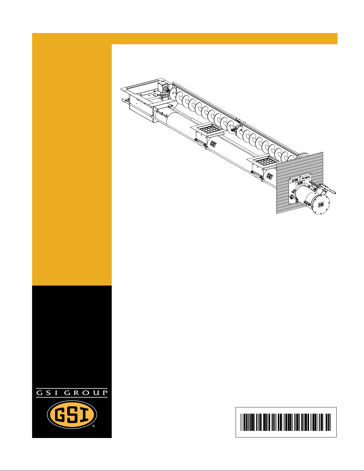
Direct Gear Drive Bin Sweep
Auger (with Roller Wells)
Assembly and Operation Manual
PNEG-1421
Date: 09-20-12
Page 2
This manual is valid for the sweep catalog numbers in the table below:
Bin Diameter 6'' DGD Sweep 8'' DGD Sweep 10'' DGD Sweep
15' GPS61503 GPS81503 18' GPS61803 GPS81803 21' GPS62103 GPS82103 24' GPS62403 GPS82403 GPS10242
27' GPS62703 GPS82703 GPS10272
30' GPS63003 GPS83003 GPS10302
33' GPS63303 GPS83303 GPS10332
36' GPS63603 GPS83603 GPS10362
39' - GPS83903 GPS10392
42' - GPS84203 GPS10422
48' - GPS84803 GPS10482
2 PNEG-1421 Direct Gear Drive Bin Sweep Auger (with Roller Wells)
Page 3

Table of Contents
Contents
Chapter 1 Introduction .......................................................................................................................................... 5
Chapter 2 Safety ..................................................................................................................................................... 6
Safety Guidelines .................................................................................................................................. 6
Safety Instructions ..................... ... .... .......................................... ... ... ..................................................... 7
Operator Qualifications ....................................................................................... .... ... ... ... .......... ... ... ... 10
Chapter 3 Safety Decals ...................................................................................................................................... 11
Chapter 4 Installation .......................................................................................................................................... 13
Power Sweep in Bins with Concrete Floors ........................................................................................ 13
Power Sweeps in Bins with Raised Metal Floors ................................................................................ 14
Intermediate Well Installation .............................................................................................................. 15
Unload Tube Installation ..................................................................................................................... 16
Install Bin Flange ................................................................................................................................. 20
Center Well Slide Gate Assembly ....................................................................................................... 22
Control Lever Installation (6" Systems) ............................................................................................... 23
Rack and Pinion Installation (8" and 10" Systems) ............................................................................. 24
Clutch Control Installation ................................................................................................................... 26
Installing the Unload Tube Flight .................. .... ... ... ... .... ... .......................................... ... ... ... ....... ......... 28
Install the Sweep Flighting .................................................................................................................. 29
Install the Flighting Shield ................................................................................................................... 33
Sweep Wheel Installation ................................. ... ... ... .... ... ... .......................................... ... ... .... ... ... ... ... 34
Chapter 5 Operation ............................................................................................................................................ 36
Power Recommendations ................................................................................................................ ... 36
Before Filling the Bin ........................................................................................................................... 37
Perform Pre-Start Checks ............................ .... ... .......................................... ... ... .... ............................ 39
Operation ............................................................................................................................................ 39
Engaging the Clutch for Bin Sweep .................................................................................................... 43
Final Clean Out ................................................................................................................... .... ... ... ... ... 44
Chapter 6 Shut Down ........................................................................................................................................... 45
Normal Shut Down .............................................................................................................................. 45
Emergency Shut Down .................................................... ... ... .... ... ... ... ... .... ... ... ................................... 45
Storage Preparation ..................................... .... ... .......................................... ... ... .... ............................ 45
Chapter 7 Maintenance ........................................................................................................................................ 46
Maintaining the Auger ......................................................................................................................... 46
Chapter 8 Troubleshooting ................................................................................................................................. 47
PNEG-1421 Direct Gear Drive Bin Sweep Auger (with Roller Wells) 3
Page 4

Table of Contents
Chapter 9 Parts List ............................................................................................................................................. 49
6" Center Well Parts ............................................................................................................................ 50
8" Center Well Parts ............................................................................................................................ 52
10" Center Well Parts .......................................................................................................................... 54
Shaft Assembly ................................................................................................................................... 56
Center Connection Parts ..................................................................................................................... 57
6" Intermediate Well Parts .......................... ................ ................. ................ ................ ........................ 58
8" Intermediate Well Parts .......................... ................ ................. ................ ................ ........................ 60
10" Intermediate Well Parts .................. ... ... ... .... ... ... ... .... .......................................... ... ... ..................... 62
6" Bin Flange Parts ............................................................................................................................. 64
8" Bin Flange Parts ............................................................................................................................. 65
10" Bin Flange Parts ........................................................................................................................... 66
6" Well Gate Control Parts .................................................................................................................. 68
8" and 10'' Rack and Pinion ................................................................................................................ 70
Assembled Sweep Arm Components ................................................................................................. 72
6", 8" and 10" Flight and Shield Bundle .............................................................................................. 74
Spacer Plates for Reduction Drive Wheel ........................................................................................... 75
Reduction Wheel Drive Components .................................................................................................. 76
Chapter 10 Warranty ............................................................................................................................................ 79
4 PNEG-1421 Direct Gear Drive Bin Sweep Auger (with Roller Wells)
Page 5

1. Introduction
READ THIS MANUAL carefully to learn how to properly use and install equipment. Failure to do so could
result in personal injury or equipment damage.
INSPECT the shipment immediately upon arrival. The customer is responsible for ensuring that all
quantities are correct. The customer should report and note any damage or shortage on the bill of lading
to justify their claim to the transport company.
THIS MANUAL SHOULD BE CONSIDERED a permanent part of your equipment and should be easily
accessible when needed.
This warranty provides you the assurance that the company will back its products when defects appear
within the warranty period. In some circumstances, the company also provides field improvements, often
without charge to the customer, even if the product is out of warranty. Should the equipment be abused
or modified to change its performance beyond the factory specifications, the warranty will become void
and field improvements may be denied.
PNEG-1421 Direct Gear Drive Bin Sweep Auger (with Roller Wells) 5
Page 6
2. Safety
This is the safety alert symbol. It is used to alert you
to potential personal injury hazards. Obey all safety
messages that follow this symbol to avoid possible
injury or death.
WARNING indicates a hazardous situation which, if not
avoided, could result in death or serious injury.
CAUTION, used with the safety alert symbol, indicates a
hazardous situation which, if not avoided, could result in
minor or moderate injury.
NOTICE is used to address practices not related to
personal injury.
DANGER indicates a hazardous situation which, if not
avoided, will result in death or serious injury.
Safety Guidelines
This manual contains information that is important for you, the owner/operator, to know and understand.
This information relates to protecting personal safety and preventing equipment problems. It is the
responsibility of the owner/operator to inform anyone operating or working in the area of this equipment
of these safety guidelines. To help you recognize this information, we use the symbols that are defined
below. Please read the manual and pay attention to these sections. Failure to read this manual and its
safety instructions is a misuse of the equipment and may lead to serious injury or death.
DANGER
WARNING
CAUTION
NOTICE
6 PNEG-1421 Direct Gear Drive Bin Sweep Auger (with Roller Wells)
Page 7
2. Safety
Follow Safety Instructions
Carefully read all safety messages in this manual and
safety signs on your machine. Keep signs in good
condition. Replace missing or damaged safety signs. Be
sure new equipment components and repair parts include
the current safety signs. Replacement safety signs are
available from the manufacturer.
Learn how to operate the machine and how to use controls
properly. Do not let anyone operate without instruction.
Keep your machinery in proper working condition.
Unauthorized modifications to the machine may impair
the function and/or safety and affect machine life.
If you do not understand any part of this manual or need
assistance, contact your dealer.
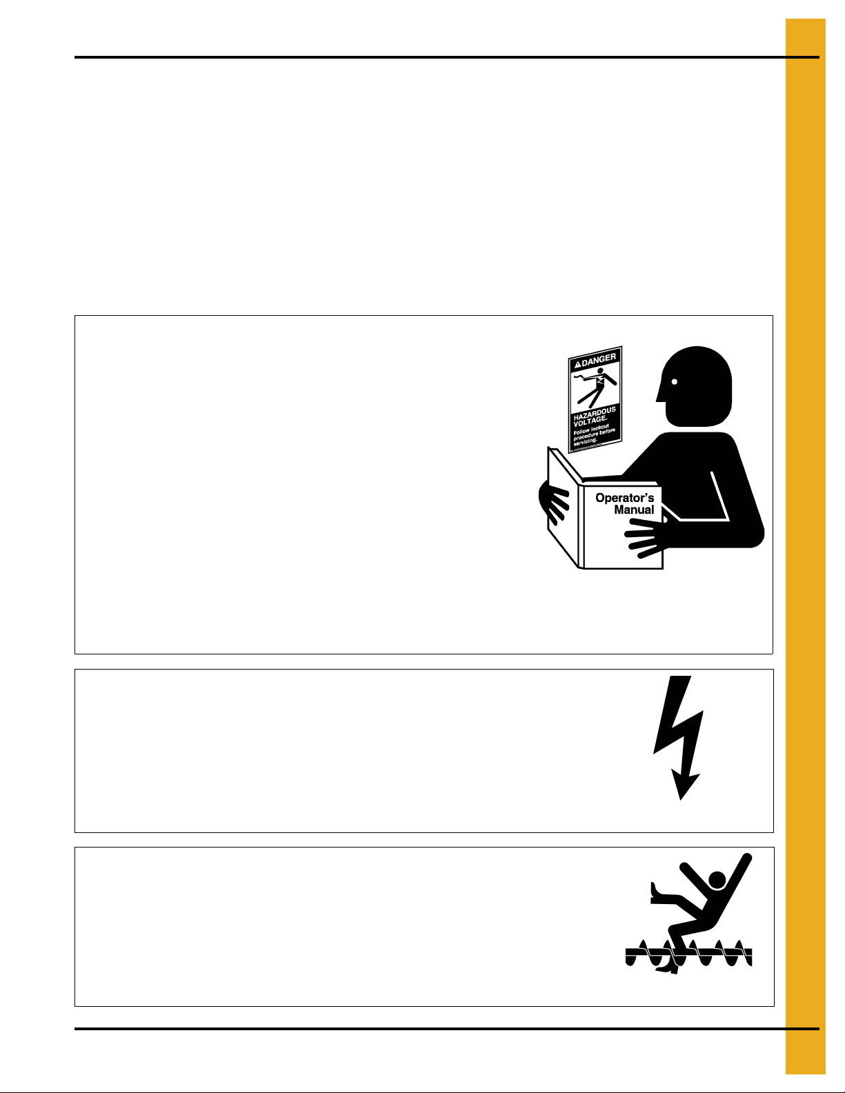
Read and Understand Manual
Install and Operate Electrical Equipment Properly
Electrical controls should be installed by a qualified electrician
and must meet the standards set by the National Electrical Code
and all local and state codes.
Disconnect and lock out all power sources before installing
wires/cables or servicing equipment.
Electric Shock Hazard
Rotating Flight
Grain augers can kill or dismember.
Keep clear of all augers and never enter the bin unless all
power is disconnected and locked out. Failure to do so will
result in serious injury or death.
Rotating Flight
Safety Instructions
Our foremost concern is your safety and the safety of others associated with this equipment. We want to
keep you as a customer. This manual is to help you understand safe operating procedures and some
problems that may be encountered by the operator and other personnel.
As owner and/or operator, it is your responsibility to know what requirements, hazards, and precautions
exist, and to inform all personnel associated with the equipment or in the area. Safety precautions may be
required from the personnel. Avoid any alterations to the equipment. Such alterations may produce a very
dangerous situation where SERIOUS INJURY or DEATH may occur.
This equipment shall be installed in accordance with the current installation codes and applicable
regulations, which should be carefully followed in all cases. Authorities having jurisdiction should be
consulted before installations are made.
PNEG-1421 Direct Gear Drive Bin Sweep Auger (with Roller Wells) 7
Page 8
2. Safety
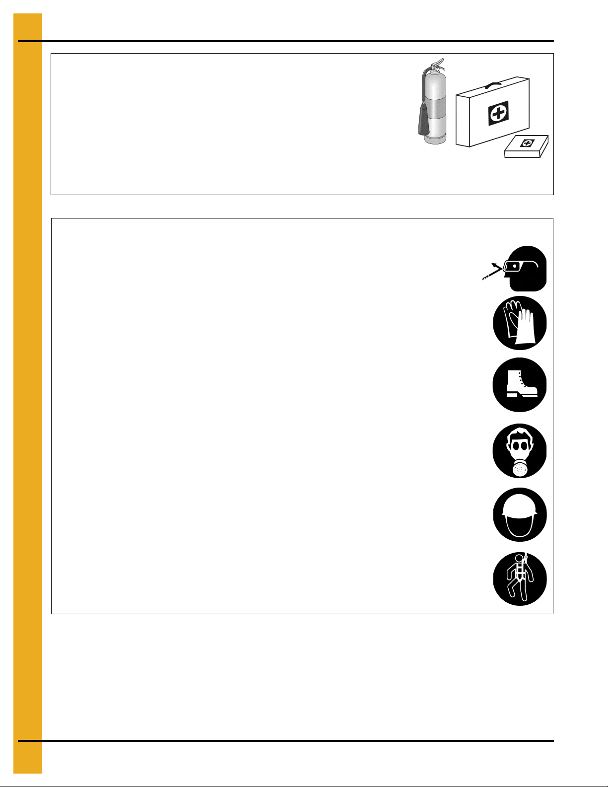
Prepare for Emergencies
Be prepared if fire starts.
Keep a first aid kit and fire extinguisher handy.
Keep emergency numbers for doctors, ambulance service,
hospital, and fire department near your telephone.
Keep Emergency Equipment
Quickly Accessible
Wear Protective Clothing
Wear close-fitting clothing and safety equipment appropriate
to the job.
Remove all jewelry.
Tie long hair up and back.
Wear safety glasses at all times to protect eyes from debris.
Wear gloves to protect your hands from sharp edges on
plastic or steel parts.
Wear steel-toed boots to help protect your feet from falling
debris. Tuck in any loose or dangling shoestrings.
A respirator may be needed to prevent breathing potentially
toxic fumes and dust.
Wear a hard hat to help protect your head.
Wear appropriate fall protection equipment when working at
elevations greater than six feet (6').
Eye Protection
Gloves
Steel-Toed Boots
Respirator
Hard Hat
Fall Protection
8 PNEG-1421 Direct Gear Drive Bin Sweep Auger (with Roller Wells)
Page 9

Operate Unload Equipment Properly
• Untrained operators subject themselves and others to SERIOUS INJUR Y
or DEATH. NEVER allow untrained personnel to operate this equipment.
• NEVER work alone.
• Keep children and other unqualified personnel out of the working
area at ALL times. Refer to the Start-Up section of this manual for
diagrams of the work area.
• Make sure ALL equipment is locked in position before operating.
• NEVER start equipment until ALL persons are clear of the work area.
• Keep hands and feet away from the auger intake and other moving parts.
• NEVER attempt to assist machinery operation or to remove trash from equipment while
in operation.
• Be sure all operators are adequately rested and prepared to perform all functions of operating
this equipment.
• NEVER allow any person intoxicated or under the influence of alcohol or drugs to operate
the equipment.
• Make sure someone is nearby who is aware of the proper shut down sequence in the event of an
accident or emergency.
• ALWAYS think before acting. NEVER act impulsively around the equipment.
• NEVER allow anyone inside a bin, truck or wagon which is being unloaded by an auger or
conveyor. Flowing grain can trap and suffocate in seconds.
• Use ample overhead lighting after sunset to light the work area.
• Keep area around intake free of obstacles such as electrical cords, blocks, etc., that might
trip workers.
• NEVER drive, stand or walk under the equipment.
• Use caution not to hit the auger when positioning the load.
• ALWAYS lock out ALL power to the equipment when finished unloading a bin.
• Be aware of pinch points. A pinch point is a narrow area between two surfaces that is likely to trap or
catch objects and so is a potential safety hazard.
Operate Unload
Equipment Safely
2. Safety
PNEG-1421 Direct Gear Drive Bin Sweep Auger (with Roller Wells) 9
Page 10
2. Safety
Operator Qualifications
A. The User/Operator must be competent and experienced to operate auger equipment. Anyone who
works with or around augers must have good common sense in order to be qualified. These persons
must also know and meet all other qualifications, such as:
i. Any person who has not read and/or does not understand all operation and safety procedures
is not qualified to operate any auger systems.
ii. Certain regulations apply to personnel operating power machinery. Personnel under the age of
18 years may not operate power machinery, including augers. It is your responsibility, as owner
and/or supervisor, to know what these regulations are in your area or situation.
iii. Unqualified or incompetent persons are to remain out of the work area.
iv. O.S.H.A. (Occupational Safety and Health Administration) regulations state: “At the time of
initial assignment and at least annually thereafter, the employer shall instruct every employee
in the safe operation and servicing of all equipment with which the employee is, or will be
involved”. (Federal Occupational Safety and Health Standards for Agriculture. Subpart D,
Section 1928.57 (a) (6)).
B. As a requirement of O.S.H.A., it is necessary for the employer to train the employee in the safe
operating and safety procedures for this auger. The sign-off sheet is provided for your convenience
and personal record keeping. All unqualified persons are to stay out of the work area at all times. It
is strongly recommended that another qualified person who knows the shut down procedure is in the
area in the event of an emergency.
Date Employee Name Supervisor Name
10 PNEG-1421 Direct Gear Drive Bin Sweep Auger (with Roller Wells)
Page 11
3. Safety Decals
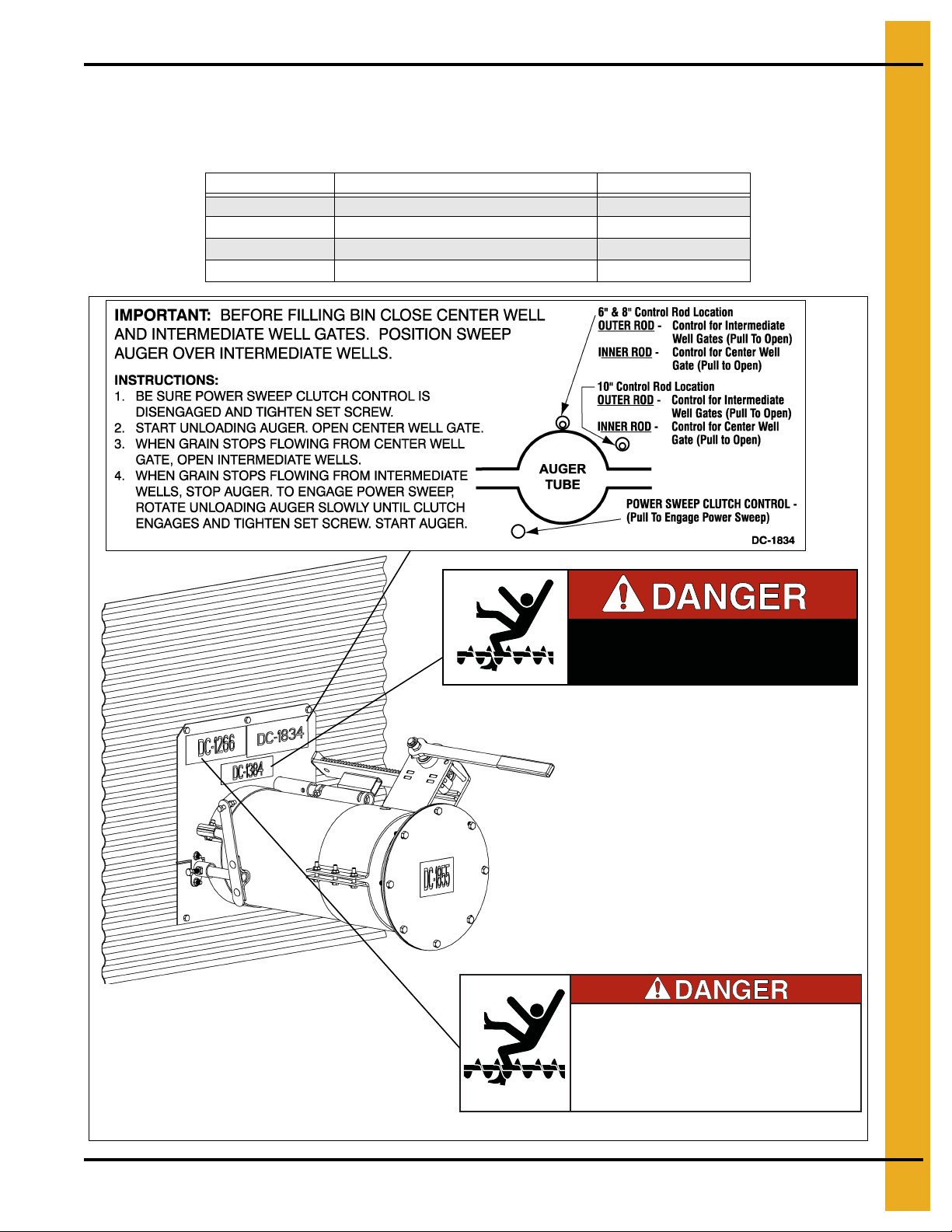
DC-1834
DC-1384
DC-1266
Check components shown below to ensure that the safety decals are in pla ce and in good condition. If a
decal cannot be easily read for any reason or has been painted over, replace it immediately. Contact your
dealer or the manufacturer to order a replacement decal free of charge.
Decal Parts List
Part # Description Size
DC-1834 Important - Power Sweep Position 7-3/8" x 2-3/4"
DC-1266 Danger - Bin Well 7-1/2" x 2-1/2"
DC-1384 Danger - Keep Out of Bin 6-1/4" x 1-1/4"
DC-1395 Danger - Rotating Flight 4-1/4" x 6-1/4"
KEEP OUT OF BIN WHILE SWEEP IS IN OPERATION
RAPIDLY TRAVELING SWEEP AUGER
FAILURE TO HEED WILL RESULT IN
SERIOUS INJURY OR DEATH
• KEEP OUT OF BIN DURING UNLOADING
OPERATIONS.
• WHEN BIN WELLS ARE IN OPEN POSITION
CONVEYING MECHANISM IS NOT COVERED.
DC-1384
FAILURE TO HEED WILL RESULT IN
SERIOUS INJURY OR DEATH!
DC-1266
PNEG-1421 Direct Gear Drive Bin Sweep Auger (with Roller Wells) 11
Page 12
3. Safety Decals
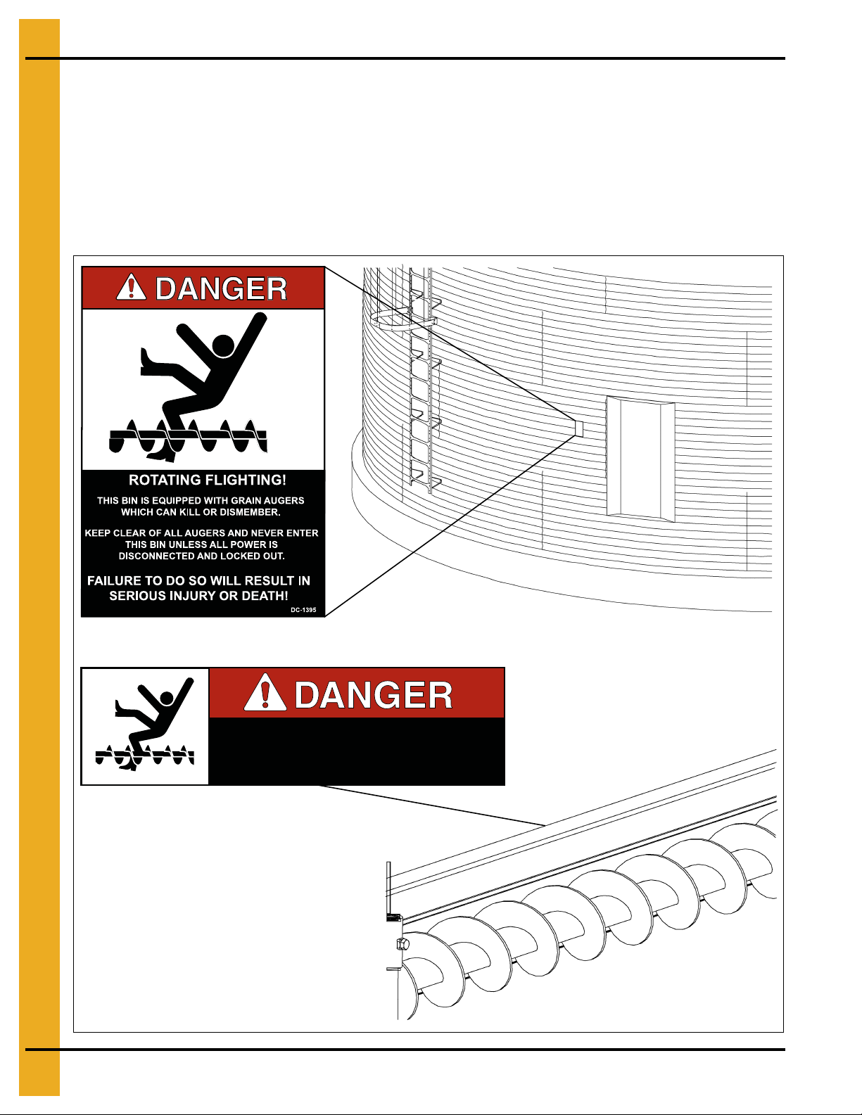
DC-1384
DC-1395
Located on the back of the
flight shield.
Check components shown below to ensure that the safety decals are in place and in good condition.
If a decal cannot be easily read for any reason or has been p ainted over, replace it immediately. Cont act
your dealer or the manufacturer to order a replacement decal free of charge.
DANGER Sign No. DC-1395 was supplied with your bin unloading equipment. This safety sign should be
applied to the side of the bin near the bin opening, so it will be viewed by people entering into the bin
storage building. Do not cover any safety signs or any other signs that are already there.
NOTE: Please remember, safety signs provide important safety information for people working near bin
unloading equipment that is in operation.
KEEP OUT OF BIN WHILE SWEEP IS IN OPERATION
RAPIDLY TRAVELING SWEEP AUGER
FAILURE TO HEED WILL RESULT IN
SERIOUS INJURY OR DEATH
12 PNEG-1421 Direct Gear Drive Bin Sweep Auger (with Roller Wells)
DC-1384
Page 13
4. Installation
Power Sweep in Bins with Concrete Floors
NOTE: The company does not recommend setting the direct gear drive bin sweep auger unit in concrete.
If installing a unit flush with a concrete floor, we recommend that the unit be installed in a
preformed trench. Use Figure 4A below.
Figure 4A Concrete Trench Layout for 6", 8" and 10" Power Sweeps
PNEG-1421 Direct Gear Drive Bin Sweep Auger (with Roller Wells) 13
Page 14
4. Installation
NOTE: Dimension “B” on Page 15.
NOTE: Dimension “B” on Page 15.
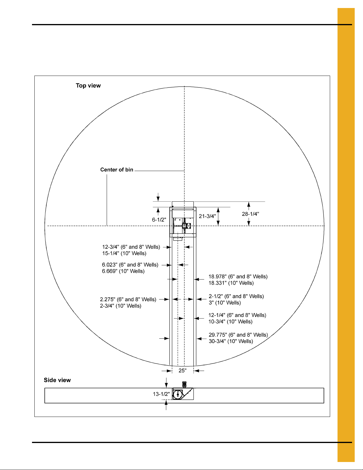
Power Sweeps in Bins with Raised Metal Floors
For bins with raised metal floors, it is necessary to cut openings in the floor for the center well and
intermediate wells. Make sure the metal floor is high enough above the concrete base so there is space
for the wells. It would be convenient to complete assembly of the bin floor as the power sweep is being
installed for better access to components under the floor.
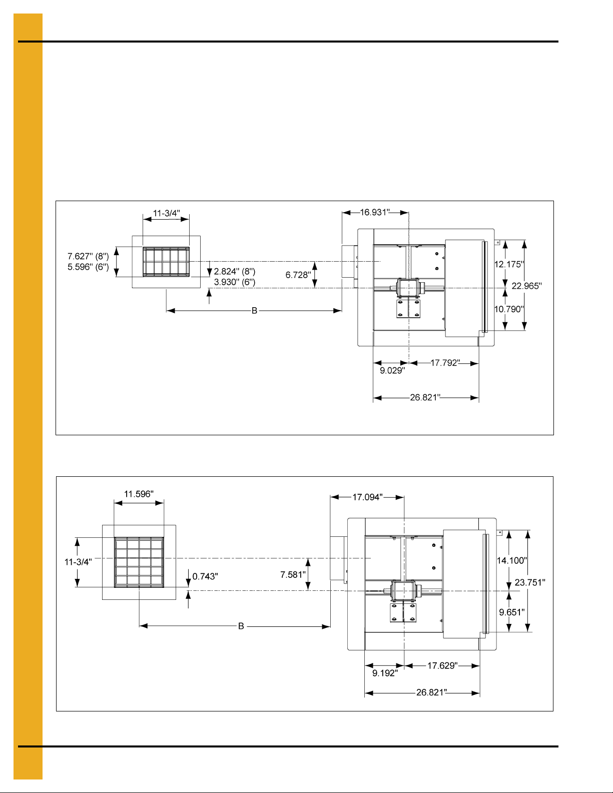
1. Locate the center of the bin and make a cut-out in the bin floor for the cen ter well. See Figure 4B for
cut-out size and location of 6" and 8" wells. See Figure 4C for 10" wells. Locate the vertical shaft
between the gearboxes in the center of the bin. Place suitable supports under the center well to hold
it in position.
Figure 4B 6" and 8" (15.24 cm 20.32 cm) Center and Intermediate Well(s) Bin Floor Cut-outs
Figure 4C 10" (25.40 cm) Center and Intermediate Well(s) Bin Floor Cut-outs
14 PNEG-1421 Direct Gear Drive Bin Sweep Auger (with Roller Wells)
Page 15
4. Installation
Intermediate Well Installation
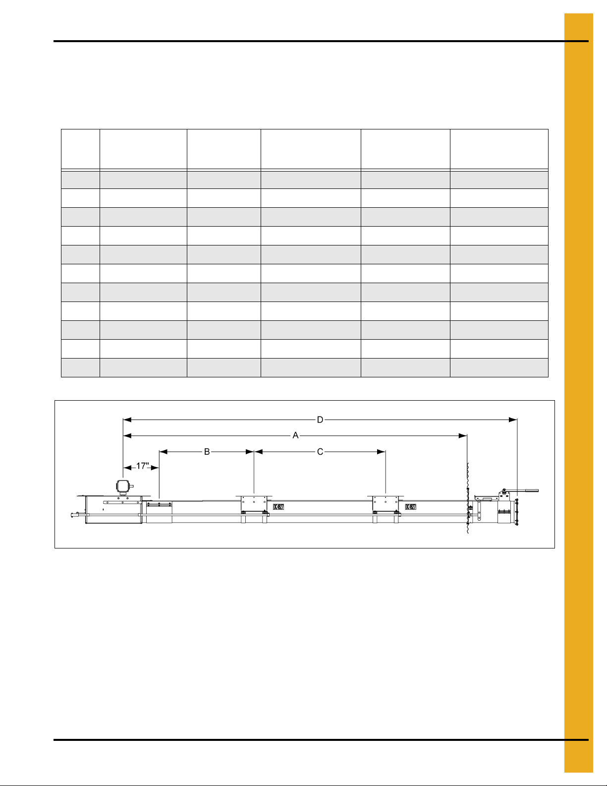
1. Cut openings in the bin floor for the intermediate wells. See Figure 4B and Figure 4C on Page 14.
The number of wells depends on bin size. The distances between intermedia te wells and the center
well should be equal. See Figure 4D and Chart below.
Bin
Size
15' 1 7' - 5-1/2" 39-3/8" * 9'-5"
18' 1 8' - 11-7/16" 36-3/4" * 1 1'-5"
21' 2 10' - 5-5/16" 32-1/2" 49-3/4" 12'-5"
24' 2 11' - 11-1/4" 38-1/2" 55-3/4" 13'-11"
27' 2 13' - 5-3/16" 44-1/2" 61-3/4" 15'-5"
30' 2 14'-11" 50-1/2" 67-3/4" 16'-11"
33' 3 16' - 4-15/16" 39.563" 56.813" 18'-1"
36' 3 17' - 10-7/8" 42.563" 59.813" 19'-11"
39' 3 19' - 4-3/4" 47.063" 64.313" 21'-5"
42' 4 20' - 10-11/16" 39" 56-1/4" 23'-5"
48' 4 23' - 10-1/2" 46.2" 63.45" 26'-5"
# of Intermediate
Wells
Distance from
Center of Bin
to Wall (A)
Distance Between
Center Well and First
Intermediate Well (B)
Distance Between
Wells (C)
Distance from
Center of Bin to
Angle Ring (D)
Figure 4D
PNEG-1421 Direct Gear Drive Bin Sweep Auger (with Roller Wells) 15
Page 16
4. Installation
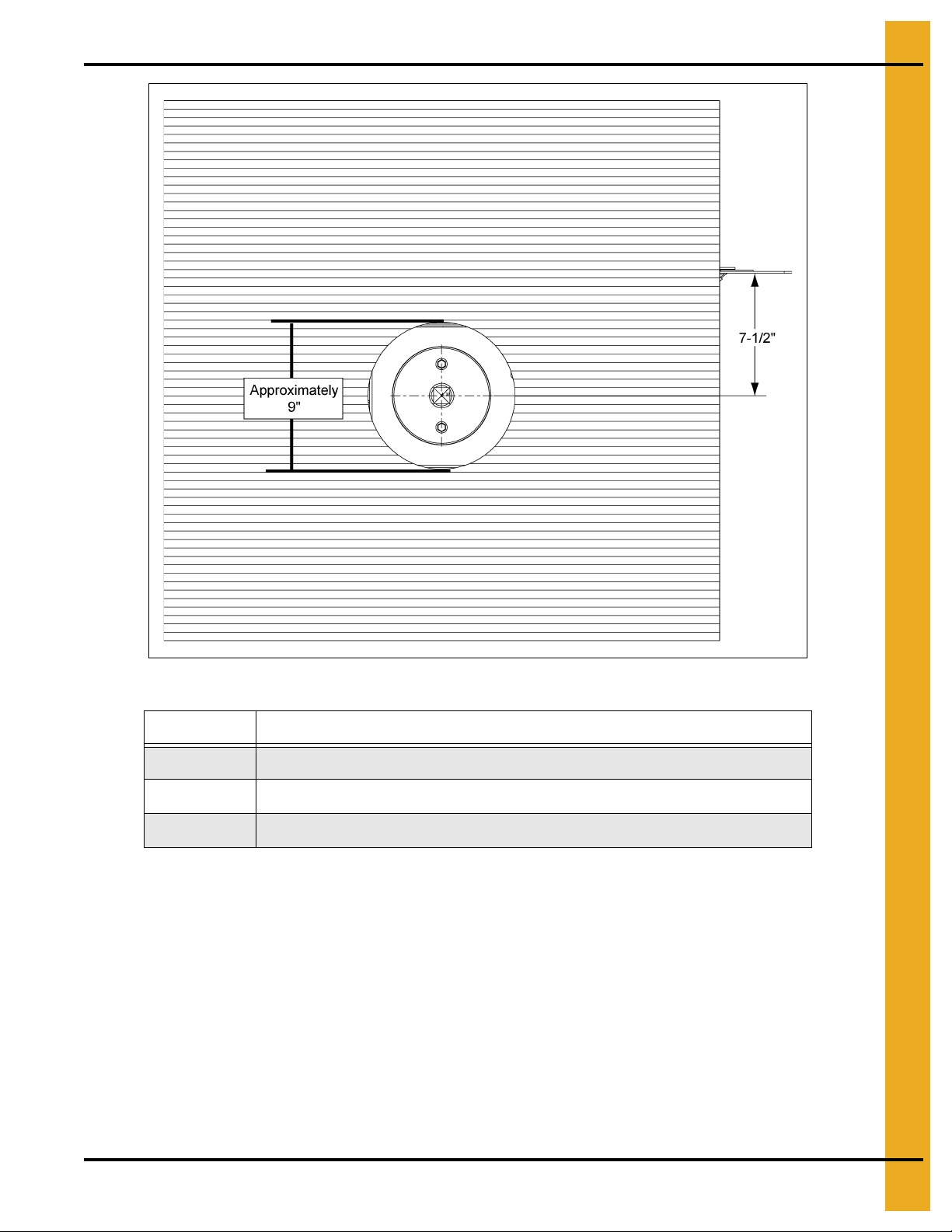
Unload Tube Installation
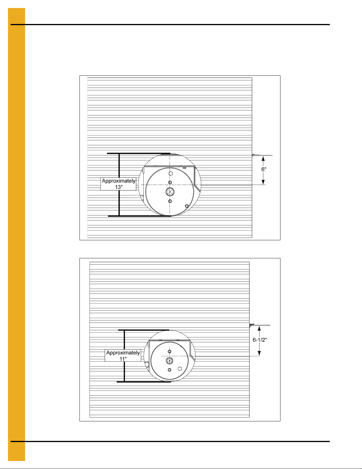
1. Cut an opening in the bin wall for the unloading tube to pass through. See Chart on Page 17 for
hole information. Additional views of the holes can be found in Figure 4E, Figure 4F below and
Figure 4G on Page 17.
Figure 4E 10" Tube
Figure 4F 8" Tube
16 PNEG-1421 Direct Gear Drive Bin Sweep Auger (with Roller Wells)
Page 17
4. Installation
Figure 4G 6" Tube
Tube Size Hole Size and Location
10" 13" Hole, approximately 6" below the bin floor, inline with the center well tube.
8" 11" Hole, approximately 6-1/2" below the bin floor, inline with the center well tube.
6" 9" Hole, approximately 7-1/2" below the floor, directly inline with the center well tube.
2. From inside the bin, insert the angle ring end of the unload tube through the hole in the bin sidewall.
NOTE: Before installing tube, remove flight from inside of tube.
PNEG-1421 Direct Gear Drive Bin Sweep Auger (with Roller Wells) 17
Page 18
4. Installation
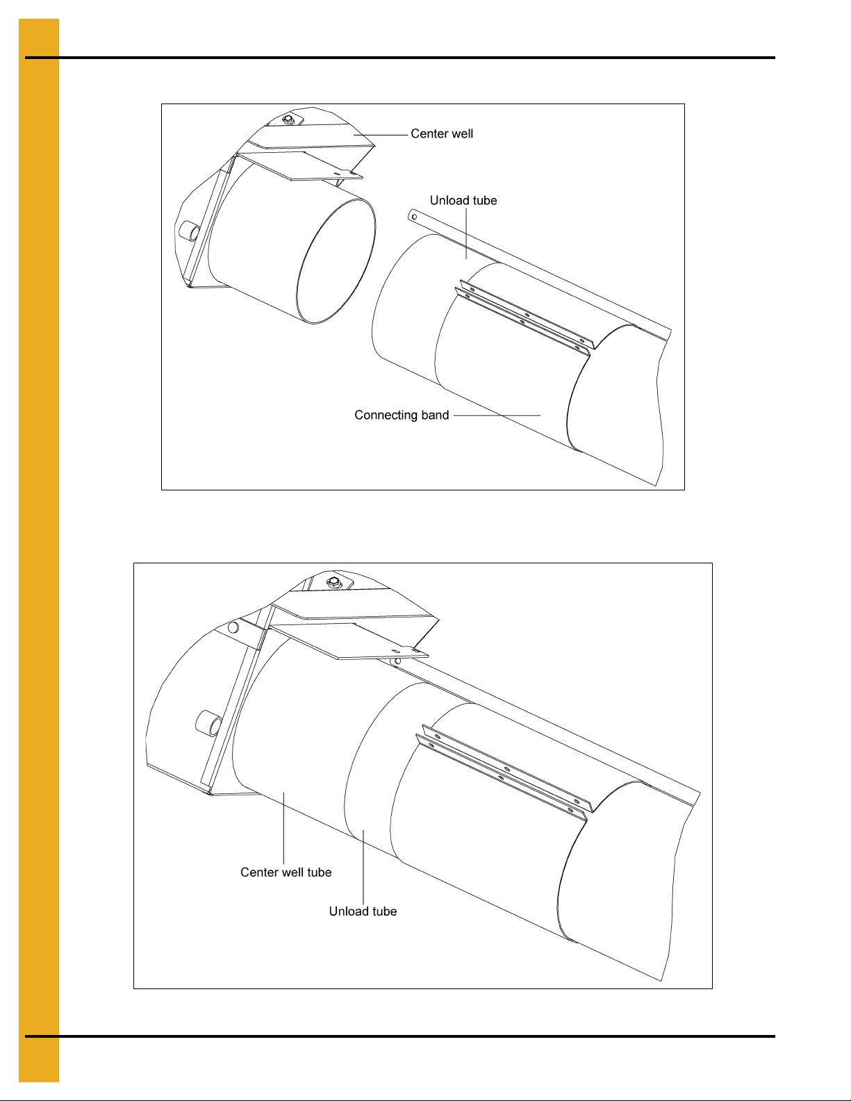
3. Place the connecting band onto the end of the unload tube closest to the center well. (See Figure 4H.)
Figure 4H
4. Position the unload tube flush against the center well tube. (See Figure 4I.)
Figure 4I
18 PNEG-1421 Direct Gear Drive Bin Sweep Auger (with Roller Wells)
Page 19
4. Installation
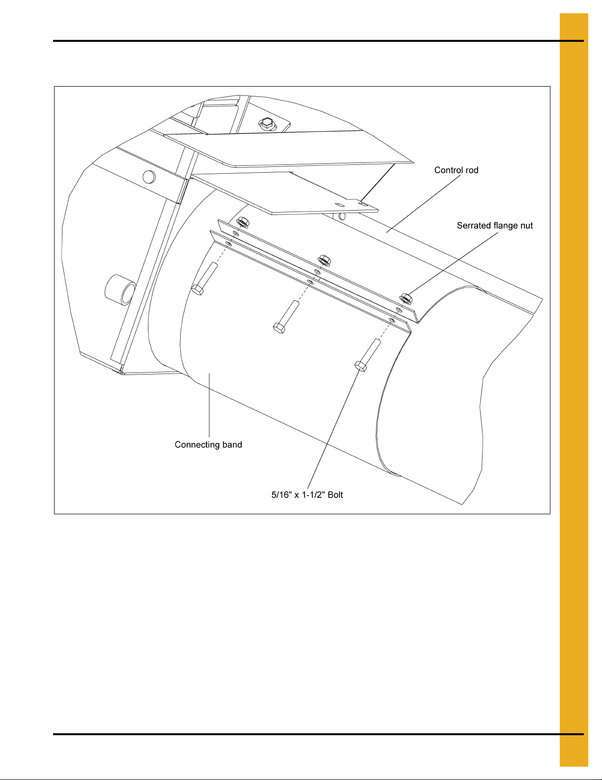
5. Slide the connecting band until it is equally positioned over both the unload tube and the center well
tube. Position the connecting band so that it will not interfere with the control rods. (See Figure 4J.)
Figure 4J
6. Secure the connecting band with three (3) 5/16" x 1-1/2" bolts and serrated flange nuts, making sure
the intermediate wells are aligned to the center wells.
PNEG-1421 Direct Gear Drive Bin Sweep Auger (with Roller Wells) 19
Page 20
4. Installation
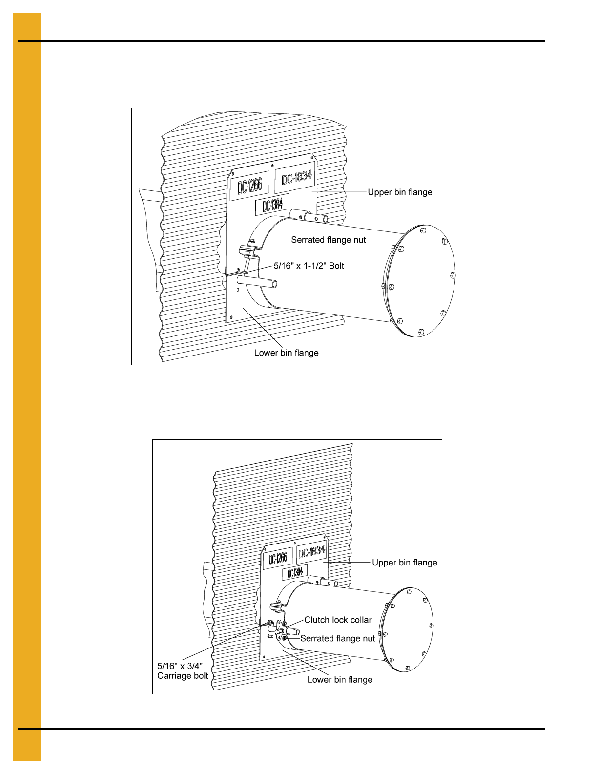
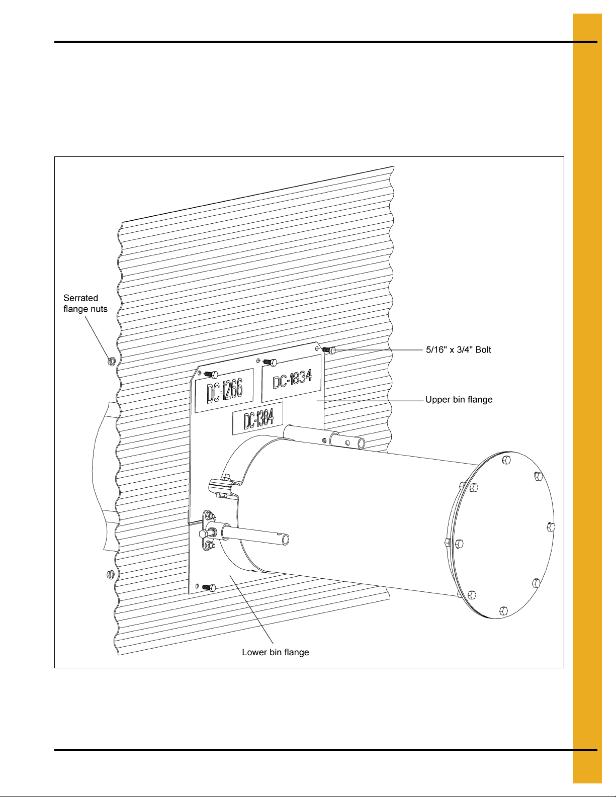
Install Bin Flange
1. Attach the upper and lower bin flanges loosely to the auger tube using two (2) 5/16" x 1-1/2" bolts
and serrated flange nuts. (See Figure 4K.)
Figure 4K
2. Next, install the clutch lock collar to the lower bin flange using two (2) 5/16" x 3/4" carriage bolts and
serrated flange nuts. Install the bolt heads on the backside of the lower bin flange so they will be next
to the bin wall when the flanges are attached to the bin. (See Figure 4L.)
Figure 4L
20 PNEG-1421 Direct Gear Drive Bin Sweep Auger (with Roller Wells)
Page 21
4. Installation
3. With the flange not yet attached to the bin wall, make sure that the bin wall opening is large enough
for the clutch and well control rods to pass through the bin wall.
4. Slide the bin flanges flush up to the bin wall and tighten the bolts connecting the two (2) flanges.
5. Drill into the bin wall through the holes located on the four (4) corners of bin flanges. Fasten the
bin flanges to the bin wall using four (4) 5/16" x 3/4" bin wall bolts and serrated flange nuts.
(See Figure 4M.)
Figure 4M
6. Drill the remaining holes into the bin wall and attach the remaining 5/16" x 3/4" bin wall bolts and
serrated flange nuts.
PNEG-1421 Direct Gear Drive Bin Sweep Auger (with Roller Wells) 21
Page 22
4. Installation
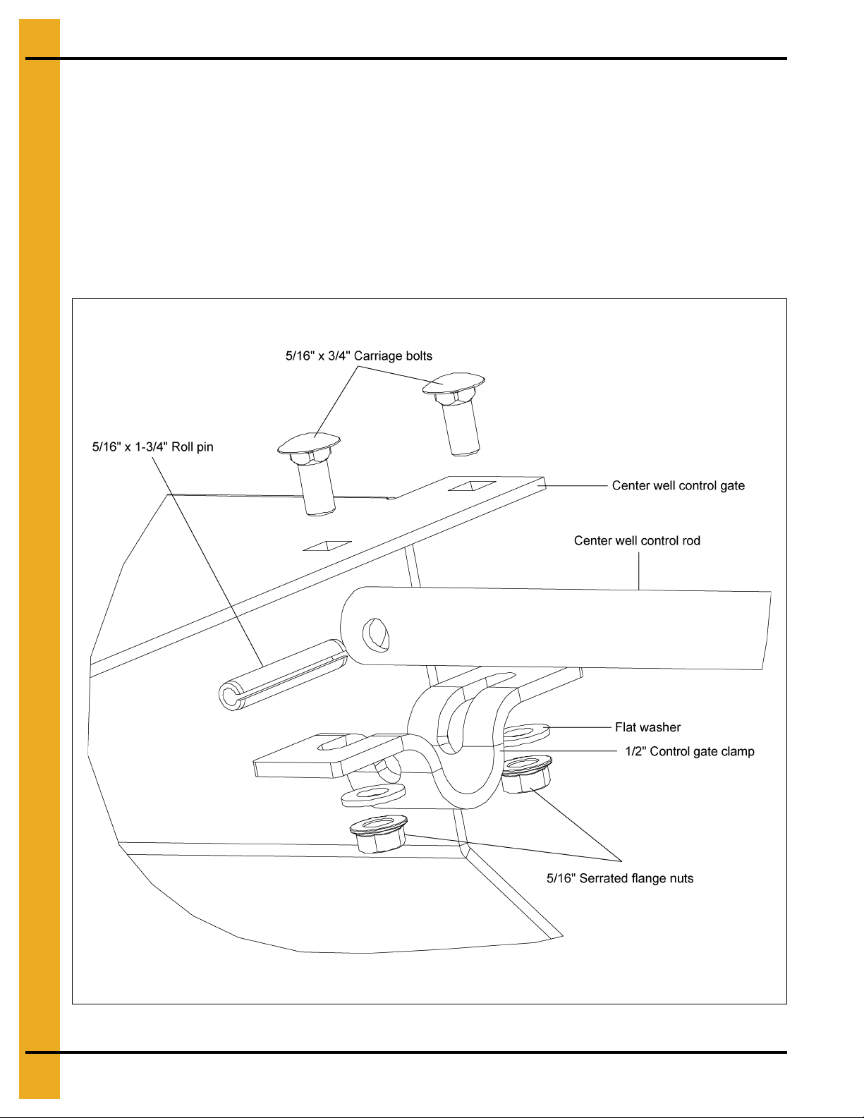
Center Well Slide Gate Assembly
1. Close the center slide gate completely.
2. Align control rod between holes in gate.
3. Attach control gate clamp to control rod by sliding 5/16" x 1-3/4" long roll pin through clamp and
control pipe.
4. Fasten clamp to bottom side of control gate by using two (2) 5/16" x 3/4" long carriage bolts,
flat washers and serrated flange nuts. (See Figure 4N.)
NOTE: 6" and 8" Rods attach on the TOP side of the center well gate.
Figure 4N
22 PNEG-1421 Direct Gear Drive Bin Sweep Auger (with Roller Wells)
Page 23
4. Installation
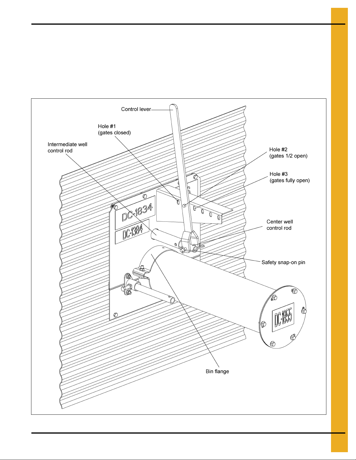
Control Lever Installation (6" Systems)
1. Close all slide control gates and keep them closed.
2. Attach the control lever by sliding the safety snap-on pin through the lever and both control rods.
Close the center well and intermediate well gates using the control lever and the various slots.
3. Place the safety snap-on pin through the center well control rod and the control lever as shown
in Figure 4O.
Figure 4O 6" Systems
PNEG-1421 Direct Gear Drive Bin Sweep Auger (with Roller Wells) 23
Page 24

4. Installation
Rack and Pinion Installation (8" and 10" Systems)
1. Make sure all gates are fully closed.
2. Slip rack and pinion tube over center gate control rod and align holes, making sure rack and pinion
is fully extended toward bin wall. (See Figure 4P.)
3. With rack and pinion resting on unload tube and tube holes aligned, insert one 5/16" x 1-3/4"
bolt through the rack and pinion tube and center gate control rod. Fasten together with a nut.
(See Figure 4P.)
Figure 4P 8" and 10" Systems
24 PNEG-1421 Direct Gear Drive Bin Sweep Auger (with Roller Wells)
Page 25

4. Installation
4. Slide wrench over shaft on rack and pinion, making sure the collar faces the gears. Fasten down with
3/8" flat washer and 3/8" x 3/4" hex bolt. (See Figure 4Q.)
Figure 4Q 8" and 10" Systems
5. With rack and pinion fully extended, attach lower half band and secure to unload tube with
six (6) 5/16" x 1-1/2" bolts, washers and serrated flange nuts. (See Figure 4R.)
6. To open all gates, with center gate closed, place second 5/16" x 1-3/4" bolt through center gate
control rod and intermediate gate control rod and secure with nut.
Figure 4R 8" and 10" Systems
PNEG-1421 Direct Gear Drive Bin Sweep Auger (with Roller Wells) 25
Page 26

4. Installation
Clutch Control Installation
1. Slide the clutch control pipe through the bin flange and the support brackets on the intermediate and
center wells. Slide the clutch control pipe into clutch collar on the center well. (See Figure 4S and
Figure 4T.)
Figure 4S
Figure 4T
26 PNEG-1421 Direct Gear Drive Bin Sweep Auger (with Roller Wells)
Page 27

4. Installation
2. Bolt the clutch control pipe to the collar on the center well using a 5/16" x 1-3/4" long bolt and
lock nut. (See Figure 4U.)
Figure 4U
3. Attach the control rod clamp to the clutch rod by sliding 5/16" x 1-3/4" long roll pin through the clamp
and control rod.
4. Fasten the clutch handle to the clamp using two (2) 5/16" x 3/4" carriage bolts, flat washers and
serrated flange nuts. The short end of the clutch handle should be closest to the bin pad, so as not
to interfere with it. Install the nuts so that they secure the roll pin in place. (See Figure 4V.)
Figure 4V
NOTE: Clutch control pipe is shipped INSIDE unload flight.
5. Check operation of clutch by pulling the handle to engage the clutch and then pushing the handle to
disengage it. The control pipe should slide freely. Lock the control pipe into the disengaged position
by tightening the bolt on the lock collar that is attached to the bin flange. (See Page 26.)
PNEG-1421 Direct Gear Drive Bin Sweep Auger (with Roller Wells) 27
Page 28

4. Installation
Installing the Unload Tube Flight
1. Begin by removing the tube end cap if you have not already done so.
2. Insert the flight into the tube with the square bushing end facing the center well and the round bushing
end facing the discharge end of the tube. (See Figure 4W.)
Figure 4W
3. When the flight is approaching the center well shaft, it will be necessary to rotate flighting
counterclockwise in order to get it to seat properly on the squared clutch shaft. When the flight is
properly seated, the flight should be entirely inside the unload tube. It may be necessary to
pull the flight out, a small amount and attempt this step multiple times in order to seat the flight
properly. (See Figure 4X.)
Figure 4X
4. On the initial stage, install with an empty bin, the installer might want to open the center well and enter
the bin to check and see that the flight is seated. Once they have seen that it has seated, they
will know the proper position of the flight on the discharge end when it has seated properly.
(See Figure 4X.)
28 PNEG-1421 Direct Gear Drive Bin Sweep Auger (with Roller Wells)
Page 29

Install the Sweep Flighting
1. Assemble the U-joint.
a. Insert the stub into the U-joint.
b. Secure the U-joint using a 5/16" x 2" roll pin. Drive the pin in with a hammer. (See Figure 4Y.)
4. Installation
Figure 4Y
2. Attach the U-joint.
a. Slide the U-joint onto the top gearbox output shaft.
b. Secure the U-joint using a 5/16" x 2" roll pin. (See Figure 4Z.)
Figure 4Z
PNEG-1421 Direct Gear Drive Bin Sweep Auger (with Roller Wells) 29
Page 30

4. Installation
(See Note for Bolt Size.)
3. Attach the pivot bracket to the left side of the gearbox using four (4) 3/8" x 3/4" flange bolts.
(See Figure 4AA.)
Figure 4AA
4. Attach a flighting section to the U-joint stub located on the gearbox. Making sure that the
Dura-Edge® side of the flight faces the center of the bin. Secure it with bolts
and stover nuts.
(See Figure 4AB.)
(See Note for Bolt Size)
NOTE: 6" Two (2) 7/16" x 3" bolts
Figure 4AB
8" Two (2) 1/2" x 3" bolts
10" Two (2) 1/2" x 3" bolts
30 PNEG-1421 Direct Gear Drive Bin Sweep Auger (with Roller Wells)
Page 31

4. Installation
(See Note for Bolt Size on Page 30.)
Use the Chart below to determine the number of flighting and shield sections needed for the length of
sweep to be used.
Bin Size
15' 1 5'-6"
18' 1 7'-0"
21' 1 8'-6"
24'
27'
30'
33'
36'
39'
42'
48'
# of Flighting and
Shields Required
1 4'-4"
1 5'-6"
1 5'-6"
1 5'-10"
1 5'-6"
1 7'-4"
1 5'-10"
1 8'-6"
1 7'-4"
1 8'-6"
1 8'-6"
1 8'-10"
1 4'-4"
1 7'-0"
1 7'-4"
1 7'-0"
2 7'-4"
Lengths
5. Insert the connecting stub into the flighting. Secure it with bolts (See Note for Bolt Size on Page 30)
and stover nuts. (See Figure 4AC.)
Figure 4AC
PNEG-1421 Direct Gear Drive Bin Sweep Auger (with Roller Wells) 31
Page 32

4. Installation
(See Note for Bolt Size on Page 30.)
6. Place the hanger bearing bracket onto the connecting stub. (See Figure 4AD.)
Figure 4AD
7. Install the next section of flighting onto the connecting stub. Secure the flighting with bolts (See Note
for Bolt Size on Page 30) and stover nuts. (See Figure 4AE.)
8. Keep repeating Step 5 on Page 31-Step 7 for additional sections of flighting.
Figure 4AE
32 PNEG-1421 Direct Gear Drive Bin Sweep Auger (with Roller Wells)
Page 33

4. Installation
Install the Flighting Shield
1. Install the first shield to the shield mounting bracket. Secure using two (2) 3/8" x 1-1/4" bolts,
flat washers and lock nuts. (See Figure 4AF.)
2. Fasten the shield bracket to the pivot bracket on the gearbox using one 1/2" x 1/2" shoulder bolt
and lock nut. (See Figure 4AF.)
Figure 4AF
3. Install the first and second flighting shield (when applicable) to the hanger bracket using two (2)
3/8" x 3" carriage bolts, flat washers and lock nuts. (See Figure 4AG.)
Figure 4AG
PNEG-1421 Direct Gear Drive Bin Sweep Auger (with Roller Wells) 33
Page 34

4. Installation
4. Install shield splice brackets to back side of flighting shields using four (4) 5/16" x 3/4" bolts,
flat washers and serrated flange nuts. (See Figure 4AH.)
Figure 4AH
5. Keep repeating Step 3 on Page 33-Step 4 for additional sections of flighting shields.
Sweep Wheel Installation
1. Insert the input shaft of the reduction drive into the open end of the flight. Attach the drive to the flight
with one 7/16" x 3" grade 8 bolt and stover nut for 6" or one 1/2" x 3" grade 8 bolt an d stover nut for
8" and 10". (See Figure 4AI on Page 35.)
2. Mount the reducer to the back shield with two (2) 3/8" x 1-1/4" serrated flange bolts, one flat washer
and nylock nut.
3. Attach the wheel hub welded assembly to the reduction drive with one 3/8" x 2-1/2" g rade 8 bolt and
stover nut.
4. Attach the rubber discs and outer wheel disc to the wheel hub welded assembly with four (4)
5/16" x 2" grade 2 bolts and nylock nuts. (See Figure 4AI on Page 35.)
34 PNEG-1421 Direct Gear Drive Bin Sweep Auger (with Roller Wells)
Page 35

4. Installation
Figure 4AI
PNEG-1421 Direct Gear Drive Bin Sweep Auger (with Roller Wells) 35
Page 36

5. Operation
Power Recommendations
1. The horsepower recommendations are for augering reasonably dry grain. High moisture grain above
(15%) will require greater power if maximum capacity is to be maintained. The maximum possible
capacity will be less with high moisture grain that with dry grain. Use and electric motor of t he correct
size that operates at 1750 RPM. DO NOT use a motor size that is greater than what is shown for the
largest bin size in the column.
2. Consideration should be given to the proper size auger for a batch drying or any intermittent type
operations. When augers are stopped and restarted under full load, it may result in damage to the
auger. Using a larger diameter auger and reducing its load level will be far better than subjecting a
smaller diameter auger to big loads. If an auger is kept from absolute filling, it will make start-up
easier and will convey more efficiently.
NOTE: The auger capacity can fluctuate greatly under varying conditions. Moisture content, different
commodities, amount of foreign matter and speeds all play a part in the performance of the
auger. Twenty-five percent (25%) moisture may cut capacity by as much as forty percent
(40%) under some conditions.
Horsepower Chart
Bin
Diameter
15' 3 3 - 3 5 - 5 5 18' 3 3 - 3 5 - 5 5 21' 3 5 - 5 5 - 5 7-1/2 24' 3 5 7-1/2 5 5 10 5 7-1/2 10
27' 5 5 7-1/2 5 5 10 5 7-1/2 10
30' 5 5 7-1/2 5 7-1/2 10 7-1/2 7-1/2 15
33' 5 5 7-1/2 5 7-1/2 10 7-1/2 7-1/2 15
36' 5 7-1/2 10 5 7-1/2 10 7-1/2 7-1/2 15
39' - 7-1/2 10 - 10 15 - - 42' - 7-1/2 10 - 10 15 - - 48' - 7-1/2 10 - 10 15 - - -
Horizontal Head 25° Head Vertical Head
6" 8" 10" 6" 8" 10" 6" 8" 10"
36 PNEG-1421 Direct Gear Drive Bin Sweep Auger (with Roller Wells)
Page 37

5. Operation
DANGER
1. Electric motors and controls must be installed by a qualified electrician and
must meet the standards set by the National Electrical Code and all local and
state codes.
2. A main power disconnect switch capable of being locked only in the OFF
position shall be provided. This shall be locked whenever work is being done on
the auger.
3. A magnetic starter should be used to protect the motor when starting and
stopping. It should stop the motor in case of power interruption, conductor fault,
low voltage, circuit interruption or motor overload. Then the motor must be
restarted manually. Some motors have built-in thermal overload protection. If this
type motor is used, use only those with a manual reset.
4. The motor starting controls must be located outside the bin. Locate the motor
starting controls outside the bin but near the bin door so the operator has full view
of the operation inside the bin.
5. Disconnect power before resetting motor overloads.
6. Reset and motor starting controls must be located so that the operator has full
view of the entire operation.
7. Make certain electric motors are grounded.
8. Shut OFF power to adjust, service or clean.
Before Filling the Bin
1. Read the instructional decal located on the upper bin flange to learn how to control the direct gear
drive power sweep well gates.
2. Push the center well and the intermediate well control rods towards the bin to close well gates.
3. With the power shut OFF and locked out, enter the bin and position the sweep auger along side of
the intermediate wells.
4. Open the center well cover plate and set it aside. While observing the clutch compon ents in the center
well, pull the clutch control pipe from the outside of the bin, until the two (2) clutch jaws are fully
engaged. Make a distinguishing mark on the clutch control rod, outside the bin, to designate the fully
engaged position.
5. Next, push the clutch control pipe toward the bin to disengage t he two (2) clutch jaws. Verify that the
clutch is fully disengaged in the center well. Make a distinguishing mark on the clutch control rod,
outside the bin, to designate the fully disengaged position.
6. Tighten the clutch control pipe position lock out bolt.
7. Reinstall the center well cover plate.
PNEG-1421 Direct Gear Drive Bin Sweep Auger (with Roller Wells) 37
Page 38

5. Operation
DO NOT enter the grain bin unless all power driven equipment has
been shut down and locked out. Never enter the grain bin unless
monitored by another person.
DO NOT enter the bin if the grain has bridged or has flowed
abnormally out of the bin as Figure 5A and Figure 5B. Suffocation
can occur if grain suddenly breaks loose, burying persons who are
inside the bin.
Figure 5A
Abnormal grain flow can easily fall and bury a person, suffocating them. DO NOT enter a bin with abno rmal
grain flow.
Bridged grain can easily break loose and bury a person, suffocating them. DO NOT enter a bin with
Figure 5B
bridged grain.
38 PNEG-1421 Direct Gear Drive Bin Sweep Auger (with Roller Wells)
Page 39

5. Operation
CAUTION
Failure to perform any or all of these pre-start checks may cause damage to the
equipment and/or cause SERIOUS INJURY or DEATH to those in the work area.
Failure to perform any or all of these pre-start checks may also be a misuse of the
equipment. Any misuse of the equipment may void the warranty.
DANGER
ALWAYS keep ALL guards and shields in place, until all the power is disconnected
and locked out.
Make certain ONLY trained operators are in the work area before operating or
moving the machine. Two (2) people must always be in a position where the
operation of the equipment can be monitored.
DO NOT start/stop the auger while it is under load, this may cause the auger
to “jam”.
Failures may occur if the auger is run full before it has been “polished” during the
“break-in” period.
CAUTION
Be aware of any unusual vibration or noises during the initial start-up and
“break-in” period. If anything unusual is detected, immediately shut down the
auger and disconnect and lock out the power supply before servicing. Visually
inspect the auger periodically during operation.
Perform Pre-Start Checks
1. Make sure ALL belts are tensioned properly.
2. Make sure ALL shields are in place and that the belt(s) and pulley(s) are able to move freely.
3. Inspect the drive unit for any problems or potential problems.
4. Be aware of any emergency shut down procedures. Two (2) people must always be in a position
where the operation of the equipment can be monitored.
5. Before starting the auger for the first time, make sure that all parts are assembled correctly according
to the instructions in this manual.
WARNING
Operation
CAUTION
CAUTION
A. Operation for 6" systems
1. Start the unloading auger. The motor is located on the power head outside the bin on the unload
tube. To figure out the horsepower needed for the equipment, use the horsepower chart
on Page 36.
2. The safety snap pin should be inserted through the center well control rod and the control lever.
Make sure it has NOT been inserted through the intermediate well control rod. (See Figure 5C
on Page 40.)
3. Place control lever in the second slot and pull lever to open gradually until the desired flow is
established. (See Figure 5C on Page 40.) It shou ld not be necessary to open the gate more than
3" to 6".
4. Always close well gates and allow the unloader to clean out before stopping the unloader.
Do not open the gate more than 3"-6" as the flow of grain into the center well will be at a higher
rate than what the unload system can remove. This will cause the auger to plug or jam.
PNEG-1421 Direct Gear Drive Bin Sweep Auger (with Roller Wells) 39
Page 40

5. Operation
Figure 5C
40 PNEG-1421 Direct Gear Drive Bin Sweep Auger (with Roller Wells)
Page 41

5. Operation
5. When grain flow stops from the center well, close the center well gate. Insert the safety snap pin
through the control lever and both the intermediate and center well control rods as Figure 5E.
The remaining grain should look similar to Figure 5D.
Figure 5D
Figure 5E
6. Gradually open gates using the middle pivot slot until the desired flow of grain is reached. You
should not open the gates more than 2" to 4". If gates need to be opened further, use the last
slot for more leverage. (See Figure 5C on Page 40.) The remaining grain should look similar
to Figure 5F.
Figure 5F
PNEG-1421 Direct Gear Drive Bin Sweep Auger (with Roller Wells) 41
Page 42

5. Operation
B. For 8" and 10" systems
1. Start the unloading auger. The motor is located on the power head outside the bin on the unload
tube. To find the horsepower needed for the equipment, use the horsepower chart on Pa ge 36.
2. Make sure the center well bolt is inserted through the rack and pinion tube and center well control
rod. Make sure the intermediate well control rod is not attached to the center well control rod.
(See Figure 5G.)
Figure 5G
3. Using the wrench on rack and pinion, open center gate until desired flow is established.
It should not be necessary to open gate more than 3" to 6". Do not open the gate more than
3" to 6" as the flow of grain into the center well will be at a higher rate than what the unload system
can remove. This will cause auger to plug or jam.
4. Always close the well gates and allow the unloader to clean out before stopping the unloader.
5. When grain flow stops from the center well, close the center well gate. Insert the intermediate
well bolt through the intermediate well control rod and the center well control rod. Remaining
grain should look like Figure 5D on Page 41.
6. Gradually open the gates until the desired flow of grain is reached. You should not open the gate
more than 2" to 4". The remaining grain should look like Figure 5F on Page 41.
42 PNEG-1421 Direct Gear Drive Bin Sweep Auger (with Roller Wells)
Page 43

5. Operation
CAUTION
The center well gate must be FULLY open during the bin sweep operation.
Engaging the Clutch for Bin Sweep
1. All power should be OFF and locked out before starting.
2. Loosen the clutch control pipe position lock bolt. Pull on the clutch handle away from the bin to
engage the clutch. Verify that the clutch is fully engaged, observing the distinguishing mark on the
control rod, as done in Step 5 in before filling the bin on Page 37.
3. Once the clutch has been engaged, tighten the clutch control pipe position lock bolt to hold the clutch
control rod in the engaged position.
4. Restore power and start the power sweep motor. The sweep auger will start along with the unload
auger. The sweep auger will remain on the floor and clear most of the grain in one pass. A second
pass will clean out additional grain, before final clean out.
Figure 5H
PNEG-1421 Direct Gear Drive Bin Sweep Auger (with Roller Wells) 43
Page 44

5. Operation
DO NOT enter a grain bin unless all power driven equipment has been shut down
and locked out.
Sweep auger
Bin wall
Bin wells
Cleaned area
Remaining grain
Sweep auger
Bin wall
Bin wells
Keep out of bin while sweep is in operation. Rapidly traveling sweep auger. The
sweep auger will move rapidly around the bin when the bin is nearly empty.
DANGER
Stay clear of the under floor unloader at the bin wells. The under floor unloader is
exposed at these locations in the bin floor.
Final Clean Out
The following procedure is recommended for cleaning the floor of the bin after the sweep auger has
removed as much grain as possible.
DANGER
1. Clean (scoop and sweep by hand) the outer area of the floor into a circular pile towards the cent er of
the bin. (See Figure 5I.)
2. Get out of the bin.
3. After making sure everyone is outside the bin and clear of the equipment, start the under floor
unloader and the sweep auger. In a short time, the circular pile towards the center of the bin will have
been removed.
4. Stop the equipment and lock out.
5. Scoop and sweep by hand the remaining floor area to the center of the bin.
6. Get out of the bin.
7. Repeat Steps 3-6 until all grain has been removed from the bin.
Figure 5I Top View of Bin
DANGER
44 PNEG-1421 Direct Gear Drive Bin Sweep Auger (with Roller Wells)
Page 45

Normal Shut Down
DANGER
NEVER start the equipment under load. Doing so may cause damage. This type of
damage is considered a misuse of the equipment. Any misuse of the equipment
may void the warranty.
DANGER
DO NOT enter the grain bin unless all power driven equipment has been
shut down.
1. Before shutting down the unit, be sure the hoppers and augers are empty.
2. Disconnect and lock out the power source before leaving the work area.
Emergency Shut Down
1. Know how to shut down the auger in case of an emergency.
2. Do not restart the auger while it is under load.
3. Close the bin well control gates.
4. Reconnect and unlock the power source.
5. Clear the auger gradually, until there is no grain and there are no obstructions.
6. Shut Down
Storage Preparation
1. Close all wells to the discharge auger.
2. Position the direct gear drive sweep directly over the intermediate wells.
NOTE: Make sure that the clutch control rods are disengaged.
3. Be sure the unload tube is empty.
4. Shut down the auger.
5. Make sure all fasteners are tight.
PNEG-1421 Direct Gear Drive Bin Sweep Auger (with Roller Wells) 45
Page 46

7. Maintenance
DANGER
Properly maintaining this equipment will help to ensure it continues to work
properly. Failure to properly maintain this equipment may result in damage to the
equipment or may cause SERIOUS INJURY or DEATH to the operator.
Failure to properly maintain this equipment may also be a misuse of the
equipment. Any misuse of the equipment may void the warranty.
Maintaining the Auger
1. The U-joint must be lubricated with SAE multipurpose grease every 10 operational hours or after
each use.
2. The upper and lower gearboxes in the center well should be half-full with oil. They must be checked
and possibly filled with SAE 80W90 gear oil every 10 operational hours. Each gearbox should be
filled up to the fill plug, approximately making them half-full overall. It is recommended to replace the
oil in the gearboxes every season.
3. Use caution when repairing or replacing equipment parts.
4. Make sure ALL decals are legible and tightly attached to the auger. If necessary, replace them FREE
OF CHARGE by contacting the dealer, warehouse or the manufacturer.
5. Mount controls for any electric motors at a safe distance from the machine and in a location
accessible in case of an emergency.
6. Make sure ALL electrical wiring is not damaged and that it meets proper wiring codes.
7. Make sure ALL components are in good working condition before use.
46 PNEG-1421 Direct Gear Drive Bin Sweep Auger (with Roller Wells)
Page 47

8. Troubleshooting
Problem Possible Cause Solution
The auger is vibrating.
Capacity is too low.
The auger plugs.
The drive belt may be too tight, binding
the head stub and flight. Damage can
occur to the auger flighting, causing
noise. Damage usually is caused from
foreign material being run through
the auger.
There may not be enough grain reaching
the auger.
The auger is moving too slowly.
The auger may be “jamming” because too
much grain is reaching the auger.
The motor may be too small or
wired improperly.
The grain may be wet.
Adjust the drive belt to the proper tightness.
It may be necessary to remove the flighting
for inspection.
Make sure the intake has not bridged
over, restricting flow. The flighting at the
intake should be covered with grain for
maximum capacity.
Check the auger speed. Low capacity will result
from speeds slower than recommended.
Decrease the amount of grain the auger
is gathering.
If the motor is a newer light weight aluminum
type, the next larger size may be desirable.
If wet grain or other hard-to-move material is
being augered, use a larger size motor than
recommended for normal use.
The sweep flight and shield
are no longer moving.
The auger may be jammed with
foreign material.
The discharge end may be plugged.
Too much drag.
Worn sweep wheel.
Unconditioned grain.
Remove any foreign material in the auger.
Unplug any plugs at the discharge end of
the auger.
Check the clearance between the shield and the
bin floor. Make sure there is room for the auger to
move. Adjusting the shield may be necessary.
The sweep wheel wears down over time.
Replace the wheel.
Moisture and/or insects can cause the grain to
harden or “Cake-up”. Disconnect and lock out
the power to the auger before go i ng into the
bin to correct this problem or to address any
other problem.
PNEG-1421 Direct Gear Drive Bin Sweep Auger (with Roller Wells) 47
Page 48

NOTES
48 PNEG-1421 Direct Gear Drive Bin Sweep Auger (with Roller Wells)
Page 49

1. 6" Center Well Parts - (See Pages 50-51.)
2. 8" Center Well Parts - (See Pages 52-53.)
3. 10" Center Well Parts - (See Pages 54-55.)
4. Shaft Assembly - (See Pages 56.)
5. Center Connection Parts - (See Pages 57.)
6. 6" Intermediate Well Parts - (See Pages 58-59.)
7. 8" Intermediate Well Parts - (See Pages 60-61.)
8. 10" Intermediate Well Parts - (See Pages 62-63.)
9. 6" Bin Flange Parts - (See Pages 64.)
9. Parts List
10. 8" Bin Flange Parts - (See Pages 65.)
11. 10" Bin Flange Parts - (See Pages 66.)
12. 6" Well Gate Control Parts - (See Pages 68.)
13. 8" and 10'' Rack and Pinion - (See Pages 70-71.)
14. Assembled Sweep Arm Components - (See Pages 72-73.)
15. 6", 8" and 10" Flight and Shield Bundle - (See Pages 74.)
16. Spacer Plates for Reduction Drive Wheel - (See Pages 75.)
17. Reduction Wheel Drive Components - (See Pages 76-77.)
PNEG-1421 Direct Gear Drive Bin Sweep Auger (with Roller Wells) 49
Page 50

9. Parts List
6" Center Well Parts
50 PNEG-1421 Direct Gear Drive Bin Sweep Auger (with Roller Wells)
Page 51

6" Center Well Parts List
Ref # Part # Description
1 GK7231 Center Well Body
2 S-2121 1/2" Flat Washer Plated, 9/16" I.D. x 1/10" x 1-3/8" O.D.
3 GC03064 1-1/2" O.D. x 5/8" Nylatron Roller
4 S-9422 1/2" Cotter Pin
5 GK1689 Offset Mounting Bracket
6 S-9067 3/8"-16 x 3/4" Serrated Flange Bolt Zinc Grade 5
7 S-968 3/8"-16 Serrated Flange Nut Zinc Grade 5
8 GK80187 Gearbox with Clockwise Rotation
9 GK1688 Gearbox Mounting Bracket
10 GK7089 Center Well Shaft Assembly
11 GK7886 Clutch Shaft Support Collar
12 S-9064 3/8"-16 x 1-1/2" Serrated Flange Bolt Zinc Grade 5
13 S-7383 3/8"-16 Nylock Nut Zinc Grade 5
14 GK4410 Flange Bearing, 1" Bore, 2 Hole w/ Lock Co llar
15 S-9066 3/8"-16 x 1-1/4" Serrated Flange Bolt Zinc Grade 5
16 GK1110 22 Tooth, Sprocket, 1" Bore, #50 w/ Keyway
17 S-9168 1/4" Square x 1" Key
18 GK1705 43P #50 Roller Chain
19 D32-0015 Connecting Link #50 Roller Chain
20 S-8760 1/2"-13 x 1-1/2" HHCS Bolt Zinc Grade 5
21 GK1702 Idler Sprocket Pivot Bracket
22 S-8260 1/2"-13 Nylock Nut Zinc Grade 5
23 S-8399 5/8"-11 x 2" HHTB Bolt Zinc Grade 5
24 S-9259 5/8"-11 Serrated Flange Nut Zinc
25 GK1701 13 Tooth Idler Sprocket, 5/8" Bore, #50 w/ Bearing
26 S-6494 5/8"-11 Deformed Lock Nut Zinc Grade 5
27 S-7470 5/16"-18 x 1" Flange Bolt Zinc Grade 5
28 S-3611 5/16"-18 Serrated Flange Nut YDP Grade 2
29 S-7382 5/16"-18 Nylock Nut Zinc Grade 5
30 S-1937 5/16" Flat Washer Zinc Grade 2
31 GK1704 Spring, Idler Bracket 5" Zinc 1/16" Pitch
32 GK1693 Clutch Pivot Bracket
33 S-6606 5/16"-18 x 3/4" Serrated Flange Bolt Zinc Grade 5
34 GK1698 Clutch Yoke
35 GK1697 Clutch Yoke Bracket
36 S-7149 5/16"-18 x 1-3/4" HHTB Bolt Zinc Grade 5
37 GK1695 Clutch Connection Rod
38 GK1694 Clutch Control Arm
39 GK7229 Center Well Drive Cover Plate
40 GK7226 Slide Gate
41 S-8999 5/16"-18 x 1/2" HHCS Bolt Zinc Grade 5
9. Parts List
PNEG-1421 Direct Gear Drive Bin Sweep Auger (with Roller Wells) 51
Page 52

9. Parts List
8" Center Well Parts
52 PNEG-1421 Direct Gear Drive Bin Sweep Auger (with Roller Wells)
Page 53

8" Center Well Parts List
Ref # Part # Description
1 GK7230 Center Well Body
2 S-2121 1/2" Flat Washer Plated, 9/16" I.D. x 1/10" x 1-3/8" O.D.
3 GC03064 1-1/2" O.D. x 5/8" Nylatron Roller
4 S-9422 1/2" Cotter Pin
5 GK1689 Offset Mounting Bracket
6 S-9067 3/8"-16 x 3/4" Serrated Flange Bolt Zinc Grade 5
7 S-968 3/8"-16 Serrated Flange Nut Zinc Grade 5
8 GK80187 Gearbox with Clockwise Rotation
9 GK1688 Gearbox Mounting Bracket
10 GK7089 Center Well Shaft Assembly
11 GK7886 Clutch Shaft Support Collar
12 S-9064 3/8"-16 x 1-1/2" Serrated Flange Bolt Zinc Grade 5
13 S-7383 3/8"-16 Nylock Nut Zinc Grade 5
14 GK4410 Flange Bearing, 1" Bore, 2 Hole w/ Lock Co llar
15 S-9066 3/8"-16 x 1-1/4" Serrated Flange Bolt Zinc Grade 5
16 GK1110 22 Tooth, Sprocket, 1" Bore, #50 w/ Keyway
17 S-9168 1/4" Square x 1" Key
18 GK1705 43P #50 Roller Chain
19 D32-0015 Connecting Link #50 Roller Chain
20 S-8760 1/2"-13 x 1-1/2" HHCS Bolt Zinc Grade 5
21 GK1702 Idler Sprocket Pivot Bracket
22 S-8260 1/2"-13 Nylock Nut Zinc Grade 5
23 S-8399 5/8"-11 x 2" HHTB Bolt Zinc Grade 5
24 S-9259 5/8"-11 Serrated Flange Nut Zinc
25 GK1701 13 Tooth Idler Sprocket, 5/8" Bore, #50 w/ Bearing
26 S-6494 5/8"-11 Deformed Lock Nut Zinc Grade 5
27 S-7470 5/16"-18 x 1" Flange Bolt Zinc Grade 5
28 S-3611 5/16"-18 Serrated Flange Nut YDP Grade 2
29 S-7382 5/16"-18 Nylock Nut Zinc Grade 5
30 S-1937 5/16" Flat Washer Zinc Grade 2
31 GK1704 Spring, Idler Bracket 5" Zinc 1/16" Pitch
32 GK1693 Clutch Pivot Bracket
33 S-6606 5/16"-18 x 3/4" Serrated Flange Bolt Zinc Grade 5
34 GK1698 Clutch Yoke
35 GK1697 Clutch Yoke Bracket
36 S-7149 5/16"-18 x 1-3/4" HHTB Bolt Zinc Grade 5
37 GK1695 Clutch Connection Rod
38 GK1694 Clutch Control Arm
39 GK7229 Center Well Drive Cover Plate
40 GK7226 Slide Gate
41 S-8999 5/16"-18 x 1/2" HHCS Bolt Zinc Grade 5
9. Parts List
PNEG-1421 Direct Gear Drive Bin Sweep Auger (with Roller Wells) 53
Page 54

9. Parts List
10" Center Well Parts
54 PNEG-1421 Direct Gear Drive Bin Sweep Auger (with Roller Wells)
Page 55

10" Center Well Parts List
Ref # Part # Description
1 GK7227 Center Well Body
2 S-2121 1/2" Flat Washer Plated, 9/16" I.D. x 1/10" x 1-3/8" O.D.
3 GC03064 1-1/2" O.D. x 5/8" Nylatron Roller
4 S-9422 1/2" Cotter Pin
5 GK4429 Offset Mounting Bracket
6 S-9067 3/8"-16 x 3/4" Serrated Flange Bolt Zinc Grade 5
7 S-968 3/8"-16 Serrated Flange Nut Zinc Grade 5
8 GK80187 Gearbox with Clockwise Rotation
9 GK4430 Gearbox Mounting Bracket
10 GK7090 Center Well Shaft Assembly
11 GK7885 Clutch Shaft Support Collar
12 S-9064 3/8"-16 x 1-1/2" Serrated Flange Bolt Zinc Grade 5
13 S-7383 3/8"-16 Nylock Nut Zinc Grade 5
14 GK4410 Flange Bearing, 1" Bore, 2 Hole w/ Lock Co llar
15 S-9066 3/8"-16 x 1-1/4" Serrated Flange Bolt Zinc Grade 5
16 GK1110 22 Tooth, Sprocket, 1" Bore, #50 w/ Keyway
17 S-9168 1/4" Square x 1" Key
18 GK6830 47P #50 Roller Chain
19 D32-0015 Connecting Link #50 Roller Chain
20 S-8760 1/2"-13 x 1-1/2" HHCS Bolt Zinc Grade 5
21 GK1702 Idler Sprocket Pivot Bracket
22 S-8260 1/2"-13 Nylock Nut Zinc Grade 5
23 S-8399 5/8"-11 x 2" HHTB Bolt Zinc Grade 5
24 S-9259 5/8"-11 Serrated Flange Nut Zinc
25 GK1701 13 Tooth Idler Sprocket, 5/8" Bore, #50 w/ Bearing
26 S-6494 5/8"-11 Deformed Lock Nut Zinc Grade 5
27 S-7470 5/16"-18 x 1" Flange Bolt Zinc Grade 5
28 S-3611 5/16"-18 Serrated Flange Nut YDP Grade 2
29 S-7382 5/16"-18 Nylock Nut Zinc Grade 5
30 S-1937 5/16" Flat Washer Zinc Grade 2
31 GK1704 Spring, Idler Bracket 5" Zinc 1/16" Pitch
32 GK1693 Clutch Pivot Bracket
33 S-6606 5/16"-18 x 3/4" Serrated Flange Bolt Zinc Grade 5
34 GK1698 Clutch Yoke
35 GK1697 Clutch Yoke Bracket
36 S-7149 5/16"-18 x 1-3/4" HHTB Bolt Zinc Grade 5
37 GK1695 Clutch Connection Rod
38 GK1923 Clutch Control Arm
39 GK7228 Center Well Drive Cover Plate
40 GK7224 Slide Gate
41 S-8999 5/16"-18 x 1/2" HHCS Bolt Zinc Grade 5
9. Parts List
PNEG-1421 Direct Gear Drive Bin Sweep Auger (with Roller Wells) 55
Page 56

9. Parts List
Shaft Assembly
Shaft Assembly Parts List
Ref # Part # Description
GK6698 Center Well Square Shaft - 6" and 8"
1
GK6699 Center Well Square Shaft - 10"
2 GK4410 Flange Bearing, 1" Bore, 2 Hole w/ Lock Collar
GK1699 13 Tooth Clutch Yoke Driver Jaw - 6" and 8"
3
GK6809 18 Tooth Clutch Yoke Driver Jaw - 10"
4 S-8902 1" O.D. x 15/16" I.D. Groove Snap Ring
5 S-8901 1/4" x 1/4" #21 Woodruff Key
6 GK1696 Clutch Yoke Driven Sliding Jaw
56 PNEG-1421 Direct Gear Drive Bin Sweep Auger (with Roller Wells)
Page 57

Center Connection Parts
9. Parts List
Center Connection Parts List
Ref # Part # Description
GK7129 Center Well Assembly - 6"
1
GK7130 Center Well Assembly - 8"
GK7131 Center Well Assembly - 10"
GK1624 Connecting Band - 6"
2
GK1677 Connecting Band - 8"
GK1796 Connecting Band - 10"
3 S-2741 5/16"-18 x 1-1/2" HHCS Bolt Zinc Grade 5
4 S-361 1 5/16"-18 Serrated Flange Nut YDP Grade 2
5 GK1726 1/2" Control Rod Clamp
6 S-8397 5/16" x 1-3/4" Spring Pin
7 S-6076 5/16"-18 x 3/4" Carriage Bolt Zinc Grade 2
8 S-1937 5/16" Flat Washer Zinc Grade 2
9 S-7149 5/16"-18 x 1-3/4" HHTB Bolt Zinc Grade 5
10 S-7382 5/16"-18 Nylock Nut Zinc Grade 5
11 GK4460 Gearbox Pivot Bracket
12 S-9067 3/8"-16 x 3/4" Serrated Flange Bolt Zinc Grade 5
GK6175 Shield Mounting Bracket - 6" and 8"
13
GK4461 Shield Mounting Bracket - 10"
14 S-10110 1/2"-13 x 1/2" Shoulder Bolt
15 S-8260 1/2"-13 Nylock Nut Zinc Grade 5
PNEG-1421 Direct Gear Drive Bin Sweep Auger (with Roller Wells) 57
Page 58

9. Parts List
6" Intermediate Well Parts
58 PNEG-1421 Direct Gear Drive Bin Sweep Auger (with Roller Wells)
Page 59

6" Intermediate Well Parts List
Ref # Part # Description
1 GC10126 6" Intermediate Well Weldment
2 GK1053 6" Half Band
3 GK6756 6" Intermediate Well Gate
4 GK6757 6" Intermediate Well Top Flange
5 GK6713 6" Control Rod Guide
6 GC00174 Control Gate Clamp with Dimple for 6" and 8"
7 GC03064 1-1/2" O.D. x 5/8" Nylatron Roller
8 S-2121 1/2" Flat Washer Plated, 9/16" I.D. x 1/10" x 1-3/8 " O.D .
9 S-7241 1/8" x 1-1/4" Cotter Pin Zinc Grade 2
10 S-4275 5/16"-18 x 3/4" HHTB Bolt Zinc Grade 5
11 S-3611 5/16"-18 Serrated Flange Nut YDP Grade 2
12 S-119 6 5/16"-18 x 1" HHCS Bolt Grade 5
9. Parts List
13 S-8999 5/16"-18 x 1/2" HHCS Bolt Zinc Grade 5
Tube (14) Flig ht (15)
Part # Description Part # Description
GK6890 6" x 15' Bin 12" Well GK7020 6" x 121-1/4" 15' Bin
GK6891 6" x 18' Bin 12" Well GK7021 6" x 145-1/4" 18' Bin
GK6892 6" x 21' Bin 12" Well GK7022 6" x 157-1/4" 21' Bin
GK6893 6" x 24' Bin 12" Well GK7023 6" x 175-1/4" 24' Bin
GK6894 6" x 27' Bin 12" Well GK7024 6" x 193-1/4" 27' Bin
GK6895 6" x 30' Bin 12" Well GK702 5 6" x 211-1/4" 30' Bin
GK6896 6" x 33' Bin 12" Well GK7026 6" x 235-1/4" 33' Bin
GK6897 6" x 36' Bin 12" Well GK7027 6" x 247-1/4" 36' Bin
PNEG-1421 Direct Gear Drive Bin Sweep Auger (with Roller Wells) 59
Page 60

9. Parts List
8" Intermediate Well Parts
60 PNEG-1421 Direct Gear Drive Bin Sweep Auger (with Roller Wells)
Page 61

8" Intermediate Well Parts List
Ref # Part # Description
1 GC10129 8" Intermediate Well Weldment
2 GK1055 8" Half Band
3 GK6759 8" Intermediate Well Gate
4 GK6760 8" Intermediate Well Top Flange
5 GK6711 8" Control Rod Guide
6 GC00174 Control Gate Clamp with Dimple for 6" and 8"
7 GC03064 1-1/2" O.D. x 5/8" Nylatron Roller
8 S-2121 1/2" Flat Washer Plated, 9/16" I.D. x 1/10" x 1-3/8" O.D.
9 S-7241 1/8" x 1-1/4" Cotter Pin Zinc Grade 2
10 S-4275 5/16"-18 x 3/4" HHTB Bolt Zinc Grade 5
11 S-3611 5/16"-18 Serrated Flange Nut YDP Grade 2
12 S-1196 5/16"-18 x 1" HHCS Bolt Grade 5
9. Parts List
Tube (14) Flight (15)
Part # Description Part # Description
GK6899 8" x 15' Bin 12" Well GK7028 8" x 121-1/4" 15' Bin
GK6900 8" x 18' Bin 12" Well GK7029 8" x 145-1/4" 18' Bin
GK6901 8" x 21' Bin 12" Well GK7030 8" x 157-1/4" 21' Bin
GK6902 8" x 24' Bin 12" Well GK7031 8" x 175-1/4" 24' Bin
GK6903 8" x 27' Bin 12" Well GK7032 8" x 193-1/4" 27' Bin
GK6904 8" x 30' Bin 12" Well GK7 033 8" x 211-1/4" 30' Bin
GK6905 8" x 33' Bin 12" Well GK7034 8" x 235-1/4" 33' Bin
GK6906 8" x 36' Bin 12" Well GK7035 8" x 247-1/4" 36' Bin
GK6907 8" x 39' Bin 12" Well GK7036 8" x 265-1/4" 39' Bin
GK6908 8" x 42' Bin 12" Well GK7037 8" x 289-1/4" 42' Bin
GK6909 8" x 48' Bin 12" Well GK7038 8" x 325-1/2" 48' Bin
PNEG-1421 Direct Gear Drive Bin Sweep Auger (with Roller Wells) 61
Page 62

9. Parts List
10" Intermediate Well Parts
62 PNEG-1421 Direct Gear Drive Bin Sweep Auger (with Roller Wells)
Page 63

10" Intermediate Well Parts List
Ref # Part # Description
1 GC10131 Intermediate Well Weldment
2 GK1057 10" Half Band
3 GK6762 10" Intermediate Well Gate
4 GK6763 10" Intermediate Well Top Flange
5 GK6714 10" Control Rod Guide
6 GC09006 Control Pipe Clamp with Dimple
7 GC03064 1-1/2" O.D. x 5/8" Nylatron Roller
8 S-2121 1/2" Flat Washer Plated, 9/16" I.D. x 1/10" x 1-3/8" O.D.
9 S-7241 1/8" x 1-1/4" Cotter Pin Zinc Grade 2
10 S-4275 5/16"-18 x 3/4" HHTB Bolt Zinc Grade 5
11 S-3611 5/16"-18 Serrated Flange Nut YDP Grade 2
12 S-1196 5/16"-18 x 1" HHCS Bolt Grade 5
9. Parts List
13 S-2741 5/16"-18 x 1-1/2" HHCS Bolt Zinc Grade 5
T ube (14) Flight (15)
Part # Description Part # Description
GK6921 10" x 24' Bin 12" Well GK7039 10" x 175-1/4" 24' Bin
GK6922 10" x 27' Bin 12" Well GK7040 10" x 193-1/4" 27' Bin
GK6923 10" x 30' Bin 12" Well GK7041 10" x 211-1/4" 30' Bin
GK6924 10" x 33' Bin 12" Well GK7042 10" x 235-1/4" 33' Bin
GK6925 10" x 36' Bin 12" Well GK7043 10" x 247-1/4" 36' Bin
GK6926 10" x 39' Bin 12" Well GK7044 10" x 265-1/4" 39' Bin
GK6927 10" x 42' Bin 12" Well GK7045 10" x 289-1/4" 42' Bin
GK6928 10" x 48' Bin 12" Well GK7046 10" x 325-1/4" 48' Bin
PNEG-1421 Direct Gear Drive Bin Sweep Auger (with Roller Wells) 63
Page 64

9. Parts List
6" Bin Flange Parts
6" Bin Flange Parts List
Ref # Part # Description
1 GC10546 6" Top Bin Flange
2 GC10547 6" Bottom Bin Flange
3 GK1619 Clutch Control Rod Position Lock Flange
4 S-3611 5/16"-18 Serrated Flange Nut YDP Grade 2
5 S-2741 5/16"-18 x 1-1/2" HHCS Bolt Zinc Grade 5
6 S-6076 5/16"-18 x 3/4" Carriage Bolt Zinc Grade 2
7 S-275 5/16"-18 x 3/4" HH BIN Bolt YDP Grade 5
8 See Page 67
9 See Page 67
10 See Page 67
11 GC12074 Clutch Control Rod Handle
12 S-8397 5/16" x 1-3/4" Spring Pin
13 GK1726 1/2" Control Rod Clamp
14 S-1937 5/16" Flat Washer Zinc Grade 2
15 S-3611 5/16"-18 Serrated Flange Nut YDP Grade 2
16 GK1206 6" End Cap
17 S-275 5/16"-18 x 3/4" HH BIN Bolt YDP Grade 5
64 PNEG-1421 Direct Gear Drive Bin Sweep Auger (with Roller Wells)
Page 65

8" Bin Flange Parts
9. Parts List
8" Bin Flange Parts List
Ref # Part # Description
1 GC10534 8" Top Bin Flange
2 GC10536 8" Bottom Bin Flange
3 GK1619 Clutch Control Rod Position Lock Flange
4 S-3611 5/16"-18 Serrated Flange Nut YDP Grade 2
5 S-2741 5/16"-18 x 1-1/2" HHCS Bolt Zinc Grade 5
6 S-6076 5/16"-18 x 3/4" Carriage Bolt Zinc Grade 2
7 S-275 5/16"-18 x 3/4" HH Bin Bolt YDP Grade 5
8 See Page 67
9 See Page 67
10 See Page 67
11 GC12074 Clutch Control Rod Handle
12 S-8397 5/16" x 1-3/4" Spring Pin
13 GK1726 1/2" Control Rod Clamp
14 S-1937 5/16" Flat Washer Zinc Grade 2
15 S-3611 5/16"-18 Serrated Flange Nut YDP Grade 2
16 GK1216 8" End Cap
17 S-275 5/16"-18 x 3/4" HH Bin Bolt YDP Grade 5
PNEG-1421 Direct Gear Drive Bin Sweep Auger (with Roller Wells) 65
Page 66

9. Parts List
10" Bin Flange Parts
10" Bin Flange Parts List
Ref # Part # Description
1 GC10560 10" Top Bin Flange
2 GC10588 10" Bottom Bin Flange
3 GK1619 Clutch Control Rod Position Lock Flange
4 S-3611 5/16"-18 Serrated Flange Nut YDP Grade 2
5 S-2741 5/16"-18 x 1-1/2" HHCS Bolt Zinc Grade 5
6 S-6076 5/16"-18 x 3/4" Carriage Bolt Zinc Grade 2
7 S-275 5/16"-18 x 3/4" HH Bin Bolt YDP Grade 5
8 See Page 67
9 See Page 67
10 See Page 67
11 GC12074 Clutch Control Rod Handle
12 S-8397 5/16" x 1-3/4" Spring Pin
13 GK1726 1/2" Control Rod Clamp
14 S-1937 5/16" Flat Washer Zinc Grade 2
15 S-456 3/8"-16 Hex Nut YDP Grade 5
16 GK2184 10" End Cap
17 S-7469 3/8"-16 x 1" HHCS Bolt Zinc Grade 5
66 PNEG-1421 Direct Gear Drive Bin Sweep Auger (with Roller Wells)
Page 67

9. Parts List
6", 8" and 10" Bin Flange Parts
Control Pipe
NOTE: All two (2) piece pipes assemble with GC05323; 3/8" NPT x 1.0" pipe connector.
Center Well Control Pipe (8) Intermediate Well Control Pipe (9) Clutch Control Pipe (10)
Bin
Size
15' GC09110 0.840" O.D. x 7' GC10360 GC11114 1" O.D. x 5' 1.851" GK1709 0.840" O.D. x 10'
18' GC09111 0.840" O.D. x 8' 6" GC10359 GC11115 1" O.D. x 6' 10.475" GK1720 0.840" O.D. x 11' 6"
21' GC09112 0.840" O.D. x 10' GC10358 GC11117 1" O.D. x 8' 6.824" GK1730 0.840" O.D. x 13'
24' GC09113 0.840" O.D. x 11' 6" GC10357 GC11118 1" O.D. x 9' 8.726" GK1744 0.840" O.D. x 14' 6"
27' GC09114 0.840" O.D. x 13' GC10356 GC11119 1" O.D. x 10' 8.726" GK1749 0.840" O.D. x 16'
30' GC09115 0.840" O.D. x 14' 6" GC10355 GC11120 1" O.D. x 11' 8.726" GK1754 0.840" O.D. x 17' 6"
33' GC09116 0.840" O.D. x 16' GC10354 GC11121 1" O.D. x 14' 1.664" GK1761 0.840" O.D. x 19' 6"
Part # Description 6" Part #
8" or 10"
Part #
Description Part # Description
36' GC09117 0.840" O.D. x 17' 6" GC10353 GC11122 1" O.D. x 515' 4.664" GK1769 0.840" O.D. x 20' 6"
GK1766 0.840" O.D. x 1'
39' GC09118 0.840" O.D. x 19' - GC11123 1" O.D. x 16' 6.164"
GK1776 0.840" O.D. x 21'
GK1784 0.840" O.D. x 2' 6"
42' GC09119 0.840" O.D. x 20' 6" - GC11124 1" O.D. x 18' 8.226"
GK1776 0.840" O.D. x 21'
48'
GK1776 0.840" O.D. x 21'
- GC11125 1" O.D. x 21'
GC09075 0.840" O.D. x 2' 6" GK1776 0.840" O.D. x 21'
GK1718 0.840" O.D. x 5' 6"
PNEG-1421 Direct Gear Drive Bin Sweep Auger (with Roller Wells) 67
Page 68

9. Parts List
6" Well Gate Control Parts
6" Well Gate Control Parts List
Ref # Part # Description
1 GK5063 6" Control Lever Handle Weldment
2 S-8480 3/8" x 2-3/4" Safety Snap Pin
68 PNEG-1421 Direct Gear Drive Bin Sweep Auger (with Roller Wells)
Page 69

NOTES
PNEG-1421 Direct Gear Drive Bin Sweep Auger (with Roller Wells) 69
Page 70

9. Parts List
8" Rack and pinion
10" Rack and pinion
8" and 10'' Rack and Pinion
70 PNEG-1421 Direct Gear Drive Bin Sweep Auger (with Roller Wells)
Page 71

8'' and 10'' Rack and Pinion Parts List
Ref # Part # Description
3 GK6838 8" Rack and Pinion Housing Assembly
3 GK6966 10" Rack and Pinion Housing Assembly
4 GK80079 8" Rack and Pinion Body Assembly
4 GK80080 10" Rack and Pinion Body Assembly
5 GC09859 Spur Gear 10DP 1" Face 22T
6 GK6841 Rack and Pinion Spacer Tube
7 GK4211 1" I.D. x 1-1/2" O.D. Flat Washer 10 Gauge Zinc
8 GK6845 Rack and Pinion Crank Shaft
9 S-4377 5/16" x 2" Grooved Roll Pin
10 GK1603 8" Half Band
10 GK5116 10" Half Band
11 S-2741 5/16"-18 x 1-1/2" HHCS Bolt Zinc Grade 5
9. Parts List
12 S-845 5/16" Flat Washer Zinc Grade 2
13 S-3611 5/16"-18 Serrated Flange Nut Zinc Grade 2
14 S-7149 5/16"-18 x 1-3/4" HHTB Bolt Zinc Grade 5
15 S-396 5/16" Hex Nut Zinc Grade 2
16 S-9067 3/8"-16 x 3/4" Serrated Flange Bolt Zinc Grade 5
17 S-248 3/8" Flat Washer Zinc Grade 2
18 GK7260 3/4" Wrench Assembly
19 GC10316 Rack Bar 10P x 1" x 14"
20 S-8999 5/16"-18 x 1/2" HHCS Zinc Grade 5
PNEG-1421 Direct Gear Drive Bin Sweep Auger (with Roller Wells) 71
Page 72

9. Parts List
Assembled Sweep Arm Components
72 PNEG-1421 Direct Gear Drive Bin Sweep Auger (with Roller Wells)
Page 73

Assembled Sweep Arm Components (Continued)
Assembled Sweep Arm Components Parts List
9. Parts List
System Ref # Part # Description
6"
8" and 10" GK4461
ALL 2 GK1266 Universal Joint 1" Bore x 5" Long
6"
8" and 10" GK5929 Universal Joint Stub Shaft 1-1/2" x 5-3/4"
6"
8" and 10" GK1951 Connecting Shaft 1-1/2" x 11-1/2"
6"
8" and 10" GK1954
ALL 6 GK5615 Shield Splice Plate
6"
8" and 10" GK7960 Reduction Wheel Drive, 7.889:1, Gear
6"
8" and 10" GK80072
6"
8" and 10" GK4241 Wheel Disc, Rubber, 13"
6"
8" and 10" GK4240
ALL 11 S-2086 3/8" -16 x 1-1/2" HHCS Bolt Zinc Grade 8
ALL 12 S-4377 5/16" x 2" Grooved Roll Pin
ALL 13 S-248 3/8" Flat Washer Zinc
ALL 14 S-7383 3/8" Nylock Nut Zinc Grade 5
6"
8" and 10" S-8315 1/2"-13 Stover Nut Zinc Grade C
6"
8" and 10" S-8252 1/2"-13 x 3" HHCS Bolt Zinc Grade 8
ALL 17 S-8055 3/8"-16 x 3" Carriage Bolt Zinc Grade 5
ALL 18 S-4275 5/16"-18 x 3/4" HHTB Bolt Zinc Grade 5
ALL 19 S-1937 5/16" Flat Washer Zinc Grade 2
ALL 20 S-3611 5/16"-18 Serrated Flange Nut Zinc Grade 2
ALL 21 S-9066 3/8"-16 x 1-1/4" Serrated Flange Bolt Zinc Grade 5
ALL 22 S-10107 3/8"-16 x 2-1/2" HHCS Bolt Zinc Grade 8
ALL 23 S-8251 3/8"-16 Stover Nut Grade C
ALL 24 S-7382 5/16" Nylock Nut Zinc Grade 5
ALL 25 S-7329 5/16"-18 x 2" HHCS Bolt Zinc Grade 2
GK6175
1
GK1678 Universal Joint Stub Shaft 1-1/4" x 5-3/4"
3
GK1736 Connecting Shaft 1-1/4" x 11-1/2"
4
GK2107
5
GK80023 Reduction Wheel Drive, 7.889:1, Gear
7
GK80071
8
GK4218 Wheel Disc, Rubber, 11"
9
GK4219
10
S-8317 7/16"-14 Stover Nut Zinc Grade C
15
S-8316 7/16"-14 x 3" HHCS Bolt Zinc Grade 8
16
Shield Mounting Bracket
Bearing Stand Assembly
Wheel Hub Welded Assembly
Outer Wheel Disc
PNEG-1421 Direct Gear Drive Bin Sweep Auger (with Roller Wells) 73
Page 74

9. Parts List
6", 8" and 10" Flight and Shield Bundle
6" Flight and Shield Bundle Parts List
Bundle # Part # Description
GK6180
GK6181
GK5017
GK6182
GK6183
GK6184
GK5018
GK6178 6" x 4'-4" Flight Weldment
GK5605 6" x 4'-4" Shield Assembly
GK5932 6" x 5'-6" Flight Weldment
GK5687 6" x 5'-6" Shield Assembly
GK2134 6" x 5'-10" Flight Weldment
GK4537 6" x 5'-10" Shield Assembly
GK5933 6" x 7'-0" Flight Weldment
GK5688 6" x 7'-0" Shield Assembly
GK6179 6" x 7'-4" Flight Weldment
GK5606 6" x 7'-4" Shield Assembly
GK5934 6" x 8'-6" Flight Weldment
GK5689 6" x 8'-6" Shield Assembly
GK2129 6" x 8'-10" Flight Weldment
GK4538 6" x 8'-10" Shield Assembly
8" and 10" Flight and Shield Bundle Parts List
Bundle # Part # Description
GK6185
GK6186
GK4827
GK6187
GK6188
GK6189
GK4828
74 PNEG-1421 Direct Gear Drive Bin Sweep Auger (with Roller Wells)
GK591 1 8"/10" x 4'-4" Fligh t Weldment
GK5757 8"/10" x 4'-4" Shield Assembly
GK5912 8"/10" x 5'-6" Flight Weldment
GK5690 8"/10" x 5'-6" Shield Assembly
GK2080 8"/10" x 5'-10" Flight Weldment
GK4740 8"/10" x 5'-10" Shield Assembly
GK5913 8"/10" x 7'-0" Flight Weldment
GK5691 8"/10" x 7'-0" Shield Assembly
GK5914 8"/10" x 7'-4" Flight Weldment
GK5756 8"/10" x 7'-4" Shield Assembly
GK5915 8"/10" x 8'-6" Flight Weldment
GK5692 8"/10" x 8'-6" Shield Assembly
GK2074 8"/10" x 8'-10" Flight Weldment
GK4745 8"/10" x 8'-10" Shield Assembly
Page 75

Spacer Plates for Reduction Drive Wheel
9. Parts List
Spacer Plates for Reduction Drive Wheel Parts List
System Part # Thickness Length Width Hole Diameter Hole Spacing
GK4209 14 Gauge
6"
GK4207 1/4"
GK4224 14 Gauge
8" and 10"
GK4226 1/4"
PNEG-1421 Direct Gear Drive Bin Sweep Auger (with Roller Wells) 75
5" 2" 7/16" 4"GK4208 12 Gauge
6" 2-1/2" 7/16" 5"GK4225 12 Gauge
Page 76

9. Parts List
Reduction Wheel Drive Components
76 PNEG-1421 Direct Gear Drive Bin Sweep Auger (with Roller Wells)
Page 77

Reduction Wheel Drive Components Parts List
9. Parts List
Ref #
GK5903 GK5904
1 GK4219 GK4240 Outer Wheel Disk
2 GK4218 GK4241 Wheel Disk, Rubb er
3 GK4217 GK4242 Inner Wh eel Weldment
4 S-7329 S-7329 5/16"-18 x 2" HHCS Bolt Zinc Grade 2
5 S-7382 S-7382 5/16"-18 Nylock Nut Zinc Grade 5
6 GK4223 GK4223 Outer Drive Housing Weldment with Bushing
7 GK4211 GK4211 1" I.D. x 1-1/2" O.D. Flat Washer 10 Gauge Zinc
8 GK4234 GK4234 #40 40T Sprocket with Hub
9 GK4215 GK4215 Hou s ing Ring with Grease Zerk
10 GK4233 GK4233 # 40 Double Roller Chain with Link
11 S-4383 S-4383 5/16" x 2-1/4" Rolled Spring Pin
12 GK4210 GK4210 1" I.D. x 1-1 /2 " O.D. Flat Washer 14 Gauge Zinc
13 GK4213 GK4228 Inner Drive Housing Weldment with Bushing
14 S-7076 S-7076 5/16"-18 x 2-1/2" HHCS Bolt Zinc Grade 5
15 GK4232 GK4233 Bearing, 1" I.D., 2 Hole Flange
16 S-968 S-968 3/8"-16 Serrated Flange Nut Zinc Grade 5
17 GK6526 GK6526 Drive Shaft, with Sprocket and Roll Pin
Part #
Description
18 DC-1687 DC-1687 Shipped without Grease Decal
Reduction Wheel Drive Additions Components Parts List
System Part # Description
Complete Drive
6" GK5903 Reduction Wheel Drive, 4:1, Chain
8" and 10" GK5904 Reduction Wheel Drive, 4:1, Chain
Bushing for Drives
6" GK4205 Bushing 1" x 1" x 4-3/8"
8" and 10" GK4206 Bushing 1-1/2" x 1" x 4-3/8"
Hardware for Flight, Bushing and Drive Shaft
6" S-6762 3/8"-16 x 2-1/2" HHCS Bolt Zinc Grade 5
8" and 10" S-8677 3/8"-16 x 3" HHCS Bolt YDP Grade 8
ALL S-8251 3/8"-16 Stover Nut Grade C
Hardware for Shield and Drive Housing
6" S-3727 3/8"-16 x 1-3/4" HHCS Bolt YDP Grade 8
8" and 10" S-8706 3/8"-16 x 1-3/4" HHTB Bolt Zinc Grade 5
ALL S-248 3/8" Flat Washer Zinc
ALL S-7383 3/8" Nylock Nut Zinc Grade 5
PNEG-1421 Direct Gear Drive Bin Sweep Auger (with Roller Wells) 77
Page 78

NOTES
78 PNEG-1421 Direct Gear Drive Bin Sweep Auger (with Roller Wells)
Page 79

10. Warranty
9101239_1_CR_rev7.DOC (revised July 2009)
GSI Group, LLC Limited Warranty
The GSI Group, LLC (“GSI”) warrants products which it manufactures to be free of defects in materials and workmanship
under normal usage and conditions for a period of 12 months after sale to the original end-user or if a foreign sale,
14 months from arrival at port of discharge, whichever is earlier. The end-user’s sole remedy (and GSI’s only obligation)
is to repair or replace, at GSI’s option and expense, products that in GSI’s judgment, contain a material defect in materials
or workmanship. Expenses incurred by or on behalf of the end-user without prior written authorization from the GSI
Warranty Group shall be the sole responsibility of the end-user.
Warranty Extensions:
The Limited Warranty period is extended for the following products:
Product Warranty Period
Performer Series Direct Drive Fan Motor 3 Years
AP Fans and Flooring
Cumberland
Feeding/Watering
Systems
Grain Systems Grain Bin Structural Design 5 Years
Grain Systems
Farm Fans
Zimmerman
All Fiberglass Housings Lifetime
All Fiberglass Propellers Lifetime
Feeder System Pan Assemblies 5 Years **
Feed Tubes (1-3/4" and 2.00") 10 Years *
Centerless Augers 10 Years *
Watering Nipples 10 Years *
Portable and Tower Dryers 2 Years
Portable and Tower Dryer Frames and
Internal Infrastructure †
5 Years
* Warranty prorated from list price:
0 to 3 years - no cost to end-user
3 to 5 years - end-user pays 25%
5 to 7 years - end-user pays 50%
7 to 10 years - end-user pays 75%
** Warranty prorated from list price:
0 to 3 years - no cost to end-user
3 to 5 years - end-user pays 50%
† Motors, burner components
and moving parts not included.
Portable dryer screens included.
Tower dryer screens not included.
GSI further warrants that the portable and tower dryer frame and basket, excluding all auger and auger drive components,
shall be free from defects in materials for a period of time beginning on the twelfth (12
and continuing until the sixtieth (60
th
) month from the date of purchase (extended warranty period). During the extended
th
) month from the date of purchase
warranty period, GSI will replace the frame or basket components that prove to be defective under normal conditions
of use without charge, excluding the labor, transportation, and/or shipping costs incurred in the performance of this
extended warranty.
Conditions and Limitations:
THERE ARE NO WARRANTIES THAT EXTEND BEYOND THE LIMITED WARRANTY DESCRIPTION SET FORTH
ABOVE. SPECIFICALLY, GSI MAKES NO FURTHER WARRANTY OF ANY KIND, EXPRESS OR IMPLIED,
INCLUDING, WITHOUT LIMITATION, WARRANTIES OF MERCHANTABILITY OR FITNESS FOR A PARTICULAR
PURPOSE OR USE IN CONNECTION WITH: (I) PRODUCT MANUFACTURED OR SOLD BY GSI OR (II) ANY ADVICE,
INSTRUCTION, RECOMMENDATION OR SUGGESTION PROVIDED BY AN AGENT, REPRESENTA TIVE OR
EMPLOYEE OF GSI REGARDING OR RELATED TO THE CONFIGURATION, INSTALLATION, LAYOUT, SUITABILITY
FOR A PARTICULAR PURPOSE, OR DESIGN OF SUCH PRODUCTS.
GSI shall not be liable for any direct, indirect, incidental or consequential damages, including, without limitation, loss of
anticipated profits or benefits. The sole and exclusive remedy is set forth in the Limited Warranty, which shall not exceed
the amount paid for the product purchased. This warranty is not transferable and applies only to the original end-user. GSI
shall have no obligation or responsibility for any representations or warranties made by or on behalf of any dealer, agent
or distributor.
GSI assumes no responsibility for claims resulting from construction defects or unauthorized modifications to products
which it manufactured. Modifications to products not specifically delineated in the manual accompanying the equipment at
initial sale will void the Limited Warranty.
This Limited Warranty shall not extend to products or parts which have been damaged by negligent use, misuse, alteration,
accident or which have been improperly/inadequately maintained. This Limited Warranty extends solely to products
manufactured by GSI.
Prior to installation, the end-user has the responsibility to comply with federal, state and local codes which apply to the
location and installation of products manufactured or sold by GSI.
PNEG-1421 Direct Gear Drive Bin Sweep Auger (with Roller Wells) 79
Page 80

This equipment shall be installed in accordance with
the current installation codes and applicable
regulations, which should be carefully followed in all
cases. Authorities having jurisdiction should be
consulted before installations are made.
Copyright © 2012 by GSI Group
Printed in the USA
GSI Group
1004 E. Illinois St.
Assumption, IL 62510-0020
Phone: 1-217-226-4421
Fax: 1-217-226-4420
www.gsiag.com
CN-300731
 Loading...