

Page 1
APCD-500
STATUS
MENUS
OUTPUT MODE
STATUS
RUN TIME HISTORY
TIME / DATE
FEED CYCLES
INSTALLATION
MANUAL MODE
ALARM
CURRENT OVERLOAD
CHAIN DISK
SAFETY SWITCH
MAX RUN TIME
FEED SWITCH
CHAIN DISK
AUGER
ACTUATOR OPEN
ACTUATOR CLOSE
MANUAL
AUTO
APCD-500
AUTO DROP FEED CONTROL
Chain Disk controller
User’s manual
M 890-00472 rev.10
REV14.
Page 2

APCD-500
Manufacturer
GSI Electronics
5200, Armand-Frappier
St-Hubert (Qc)
Canada J3Z 1G5
WARN ING S
The war ranty can be void if t his prod uct is used in a m anner
not specifie d by the manufacturer.
Every effort has been m ade to ens ure that t his manu al is
complete, accurate and up-to-date. The information contained in it is however subject to change without notice
due to further developments.
2
APCD-500, rev10
Page 3

APCD-500
TABLE OF CONTENTS
1. INTRODUCTION .....................................................................5
1.1. Precautions ........................................................................... 5
1.2. Symbols of the Manual ........................................................... 5
2. USER INTERFACE ..................................................................6
2.1. Location of the Controls ......................................................... 6
2.2. Adjusting a Parameter ............................................................ 7
3. MOUNTING INSTRUCTIONS ....................................................7
3.1. Mounting the Controller on the Wall ......................................... 7
3.2. Connections .......................................................................... 7
4. CONTROLLER OVERVIEW .......................................................8
4.1. Features ............................................................................... 8
4.2. Chain Disk System Setups ...................................................... 8
4.2.1. Cascade Setup .................................................................8
4.2.2. Independent Chain Disk Systems with a Common Auger .......9
4.2.3. Independent Chain Disk Systems with Individual Augers ........9
4.3. Feed Distribution Modes ......................................................... 10
4.3.1. Timed Feed Distribution .....................................................10
4.3.2. Continuous Feed Distribution ..............................................10
4.4. Filling Process ....................................................................... 11
4.4.1. Filling Cascaded Chain Disk Systems with Continuous Feed
Distribution Mode .............................................................13
4.4.2. Filling Cascaded Chain Disk Systems with Timer Mode ..........15
4.4.3. Filling Independent Chain Disk Systems with a Common Bin
Auger using Continuous Feed Distribution Mode ...................18
4.4.4. Filling Independent Chain Disk Systems with a Common Bin
Auger using Timer Mode ....................................................20
4.4.5. Filling Independent Chain Disk Systems with Individual Bin Au-
gers Using Continuous Feed Distribution Mode .....................23
4.4.6. Filling Independent Chain Disk Systems with Individual Bin Au-
gers Using the Timed Feed Distribution Mode .......................25
4.5. Feed Delivery Process ............................................................. 28
4.6. Feed Cycle ............................................................................ 28
5. PARAMETER SETTINGS .........................................................29
5.1. Controller Status .................................................................... 29
5.2. Run Time History ................................................................... 29
5.3. Time & Date .......................................................................... 30
5.3.1. Adjusting Improper System Time ........................................30
5.4. Feed Cycle Settings ............................................................... 30
APCD-500, rev10
3
Page 4

APCD-500
5.5. Run Time Settings .................................................................. 32
5.6. Installation Setup ................................................................... 32
5.7. Manual & Test Modes ............................................................ 37
5.7.1. Manual Filling of the Chain Disk Systems .............................37
5.7.2. Manual Start / Stop ...........................................................37
5.7.3. Bypassing a Chain Disk System ..........................................38
5.7.4. Manual Dump ...................................................................38
5.7.5. Toggle Switch ..................................................................39
5.7.6. Test Mode .......................................................................39
5.8. Alarms.................................................................................. 40
5.8.1. Acknowledging an alarm ....................................................40
6. TECHNICAL SPECIFICATIONS .................................................41
7. TRANSFER MENU ..................................................................42
7.1. Communication Speed ............................................................ 42
7.2. Screen Contrast .................................................................... 42
7.3. Update/Backup with a USB drive .............................................. 42
ANNEX 1: CORE CARD ...................................................................44
INDEX ..........................................................................................45
4
APCD-500, rev10
Page 5
APCD-500
1. INTRODUCTION
1.1. Precautions
WARNING: Read and save these
instructions!
Safety may be jeopardized if the equipment
is used in a manner not specified by the
manufacturer. Carefully read and keep the
following instructions for future reference.
Although fuses at the input and outputs of
the controller protect its circuits in case of
an overload or over-voltage, we recommend
installing an additional protection device on
the controller’s supply circuit.
The room temperature where the controller
is located must always remain between 32°F
and 104°F (0°C to 40°C). Indoor use only!
To avoid exposing the controller to harmful
gases or excessive humidity, it is preferable
to install it in a corridor.
If the equipment is used in a manner not
specified by the manufacturer, the protection provided by the equipment may be
impaired.
1.2. Symbols of the Manual
Warning. Read the following text
carefully; it contains important
information which, if ignored, may
cause the controller to operate
improperly.
High Voltage. Hazard of electrical
shock. Read the message and follow
the instructions carefully.
Pay attention. The following text
contains very useful information.
Double insulation.
Both direct and alternating current
(AC/DC).
Direct current (DC).
Alternating current (AC).
For Customer Use: Enter below the serial
number located on the side of the alarm
system and keep this information for future
reference.
Do not spray water on the controller! In
order to clean the control, wipe it with a
damp cloth.
Before servicing or cleaning unit,
switch power off at service panel
and lock the switch disconnecting
means to prevent power from being
switched accidentally. When the service disconnecting means cannot be
locked, securely fasten a prominent
warning device, such as a tag, to the
service panel.
Model: APCD-500
Serial number:
Date installed:
APCD-500, rev10
5
Page 6
APCD-500
2. USER INTERFACE
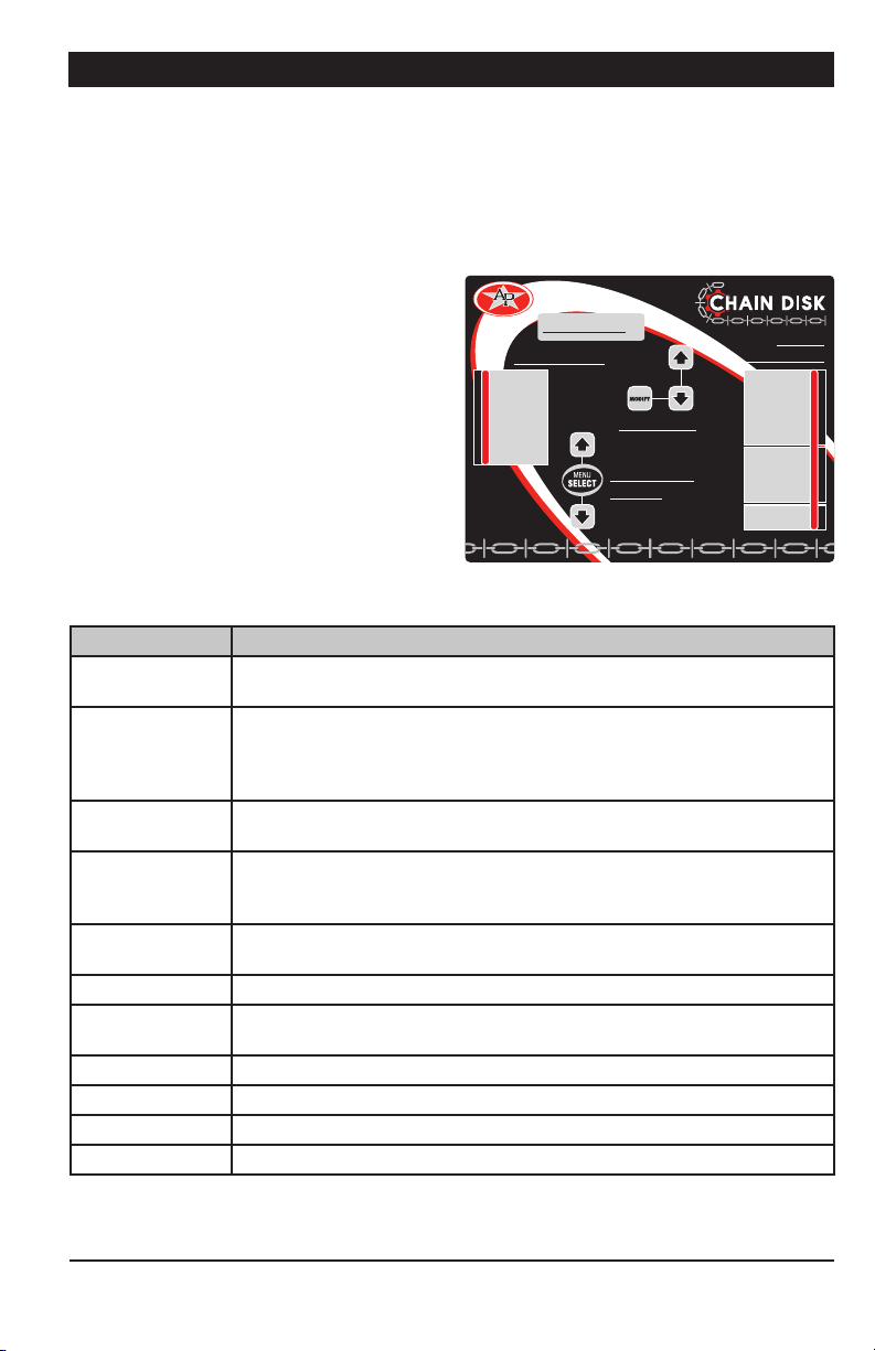
2.1. Location of the Controls
Function LED — This pilot light shows what
function is selected on the main menu.
Menu Select Buttons — These buttons are
used to select a function from the main menu.
LCD Display — The LCD display on the left
Function LE D
STATUS
RUN TIME HISTORY
MENUS
TIME / DATE
FEED CYCLES
INSTALLATION
MANUAL MODE
APCD-500
AUTO DROP FEED CONTROL
LCD Display
Arrow keys
Menu s elect
buttons
status LEDs
CURRENT OVERLOAD
SAFETY SWITCH
MAX RUN TIME
FEED SWITCH
ACTUATOR OPEN
ACTUATOR CLOSE
gives the current readings and parameters
to be adjusted when you select a function.
It automatically displays the STATUS menu
after 4 minutes of inactivity.
Arrow keys — The arrow keys next to the
LCD display are used to scroll down the
parameters on screen. They are also used
to change the value of the parameters inside
editing pop-up menus.
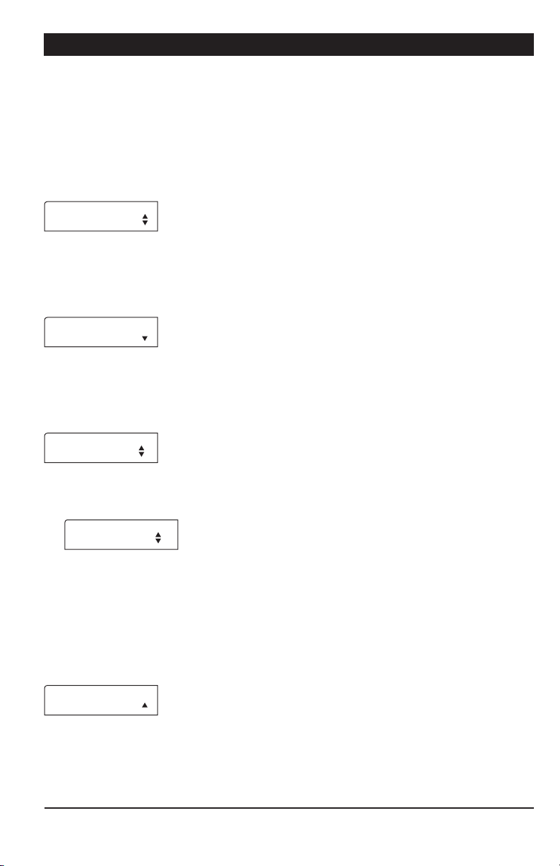
Output Status LEDs — The table below gives
the meaning of each output status pilot light :
LED MEANING
Alarm Turns on when an alarm is detected. The Chain Disk stops operating
until the alarm is acknowledged.
Current Overload Turns on when the amperage draw of the master Chain Disk exceeds
the Max Current limit for the Overload Delay or flashes when this
situation happens with a slave Chain Disk. Fix the problem and then
acknowledge the alarm to restart the system.
Chain Disk
safety switch
Max run time
Turns on when the drive unit of the Chain Disk has reached its safety
switch; flashes when this occurs to a slave Chain Disk (APCD-500-S).
Turns on when the run time of the Chain Disk exceeds the Max Run
Time parameter value (only if a proximity sensor is used); flashes when
this occurs to a slave Chain Disk (APCD-500-S).
Feed switch Turns on when the proximity sensor detects feed.
Flashes during the Feed Bypass Delay.
Chain disk Turns on when the master Chain Disk System is running.
Auger output Turns on when the bin auger is running; flashes during the Auger
Delay.
Actuator open Turns on when the dumps are opened.
Actuator close Turns on when the dumps are closed.
Manual mode Turns on when an output is manually controlled.
Automatic mode Turns on when the automatic control mode is active.
Output
ALARM
CHAIN DISK
CHAIN DISK
AUGER
MANUAL
AUTO
STATUS
OUTPUT MODE
6
APCD-500, rev10
Page 7

APCD-500
2.2. Adjusting a Parameter
Use the arrow keys to select the parameter
that needs to be adjusted. When it is selected,
press MODIFY to display the pop-up window
for adjusting the parameter. Now, use the arrow keys to modify the parameter’s value and
then press the MODIFY button again to validate
the change.
3. MOUNTING INSTRUCTIONS
3.1. Mounting the Control-
ler on the Wall
Remove the four screws in the front cover
and lif t the cover. Remove the black caps located on the three mounting holes. Mount the
enclosure to the wall using three screws. Be
sure the electrical knockouts are at the bottom of the enclosure in order to prevent water
from entering the controller. Insert the screws
into the mounting holes and tighten. Fasten
the black caps onto the mounting holes.
• Do not install rigid conduit into electrical
knockouts. Only nylon cable glands are permitted for cable or wire fastening.
• The controller has no power-on switch.
An external switch or circuit breaker shall be
included in the building installation to interrupt power to L and N electric power lines. It
shall be in close proximity to the equipment
and within easy reach of the operator. It shall
be marked as the disconnecting device for
the equipment.
• The main supply circuit breaker for Chain
Disk motor (L1/L2 POWER IN) shall be no
larger than 20 A.
• Wire gage used for mains supply (L1/L2
POWER IN) and Chain Disk motor shall be at
least 12 AWG.
• Separate circuit breaker shall be used for
auger motor.
• The mains supply breaker for auger motor
shall be 15 A.
• Wire gage used for Flex-Flo auger motor
shall be at least 14 AWG.
3.2. Connections
To connect the controller, refer to the wiring
diagram enclosed with this user’s manual.
Use the electrical knockouts provided at the
bottom of the enclosure. Do not make additional holes in the enclosure, particularly
on the side of the enclosure when using a
computer communications module.
All wiring must be done by an authorized electrician and must comply
with applicable codes, laws and regulations. Be sure power is off before
doing any wiring to avoid electrical
shocks and equipment damage.
Safety may be jeopardized if the equipment
is used in a manner not specified by the
manufacturer.
APCD-500, rev10
7
Page 8
APCD-500
4. CONTROLLER OVERVIEW
4.1. Features
The APCD-500 controls the feed entry into
Chain Disk Systems and the distribution of
feed to the animals. When used in combination with APCD -500-S auxiliary units, this
controller can control up to 8 Chain Disk
Systems.
Due to its great number of options, the
APCD-500 controller can suit most Chain
Disk setups:
4.2. Chain Disk System Setups
Up to 7 slave units (APCD-500-S) can be
used to drive additional Chain Disk Systems.
These supplementary Chain Disk Systems
can share common bin augers, they can be
linked together, or they can operate independently one from another. The following
section explains the three possible Chain
Disk System setups that can be managed by
the controller. Refer to the Installation Setup
chapter to select your specific Chain Disk
System setup.
• Timed or continuous feed cycles;
• With or without proximity sensors.
• With or without actuators / air valves to
open the drops;
• With commun or individual bin augers;
• With one or multiple Chain Disk Systems;
• With cascade or independent Chain Disk
setups.
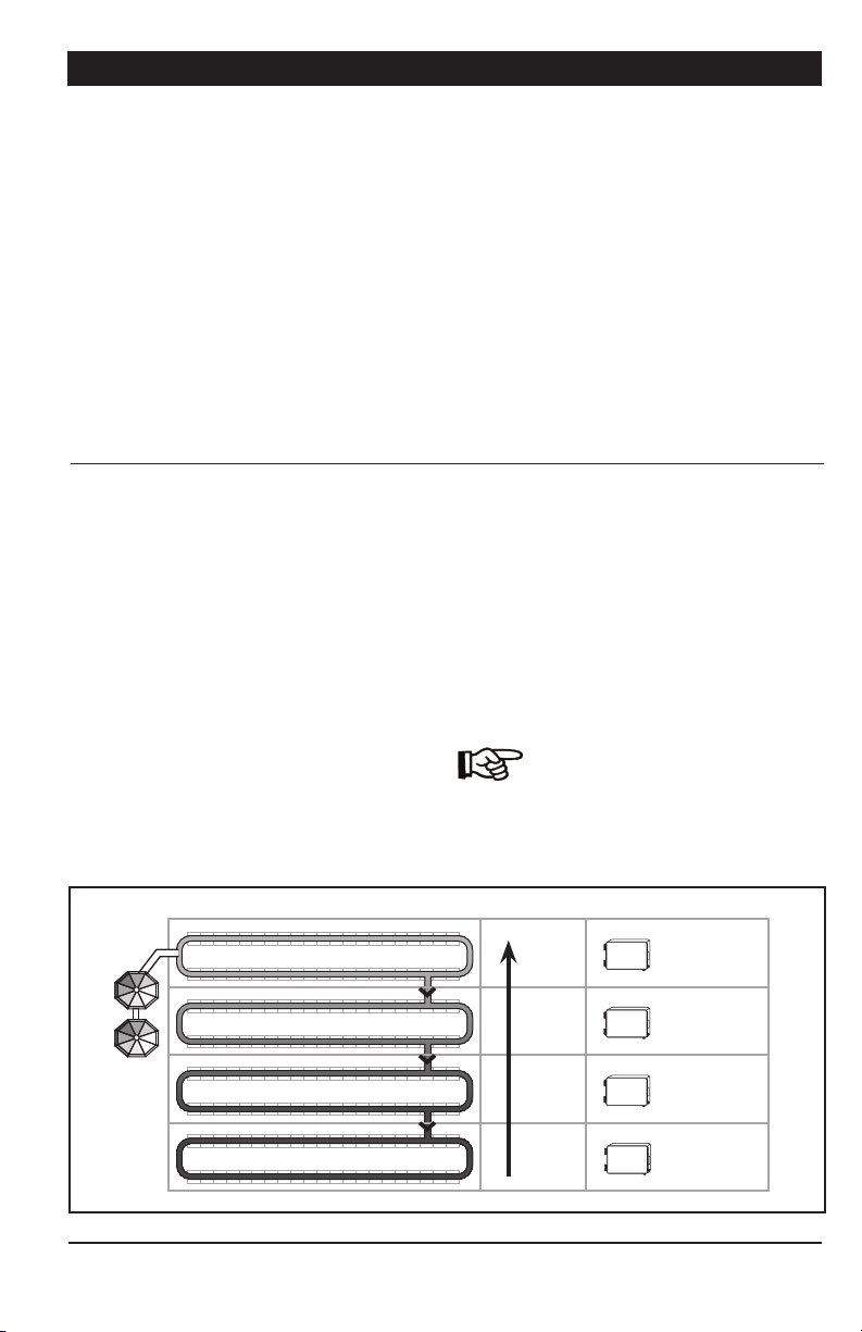
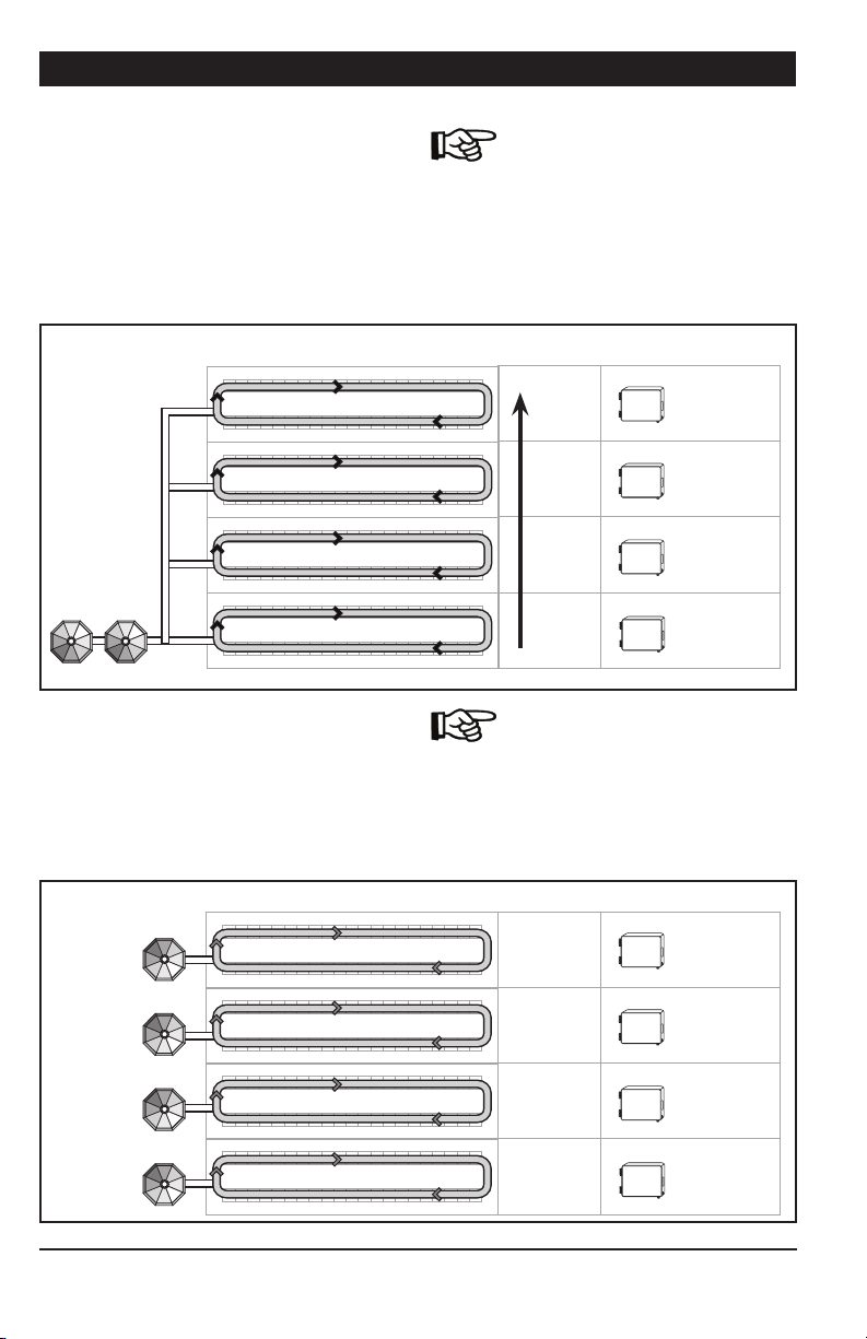
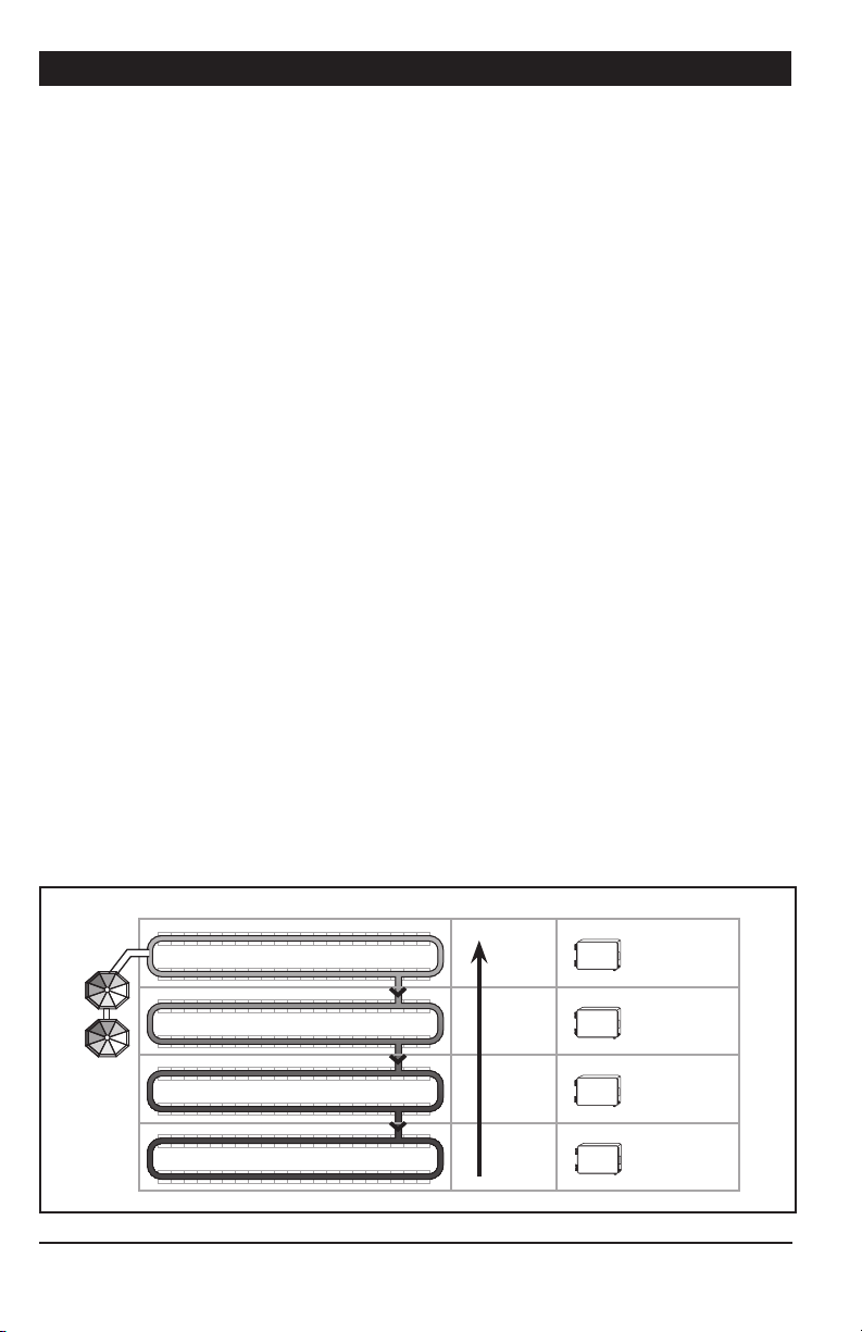
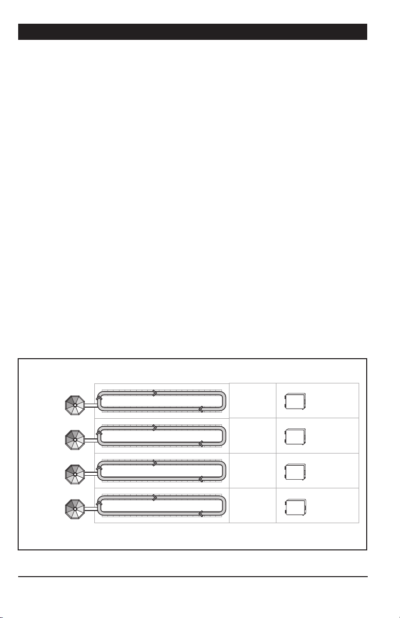
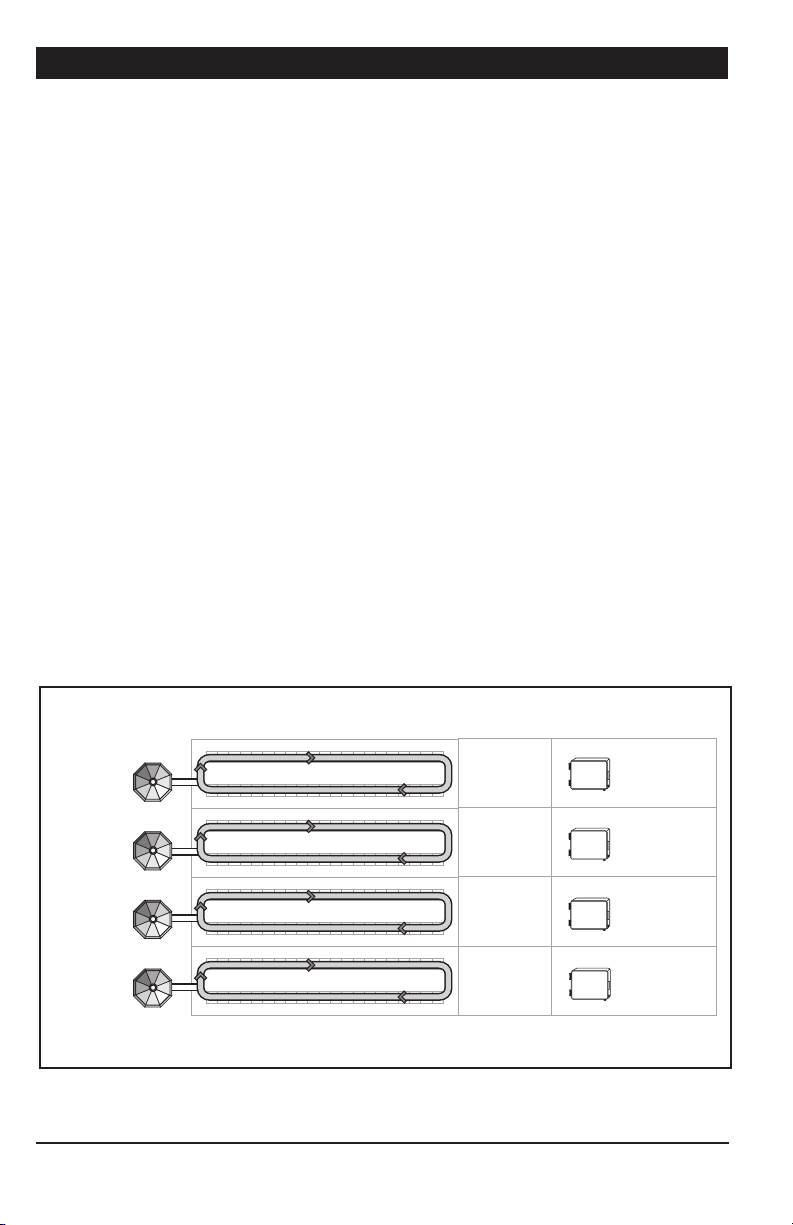
4.2.1. Cascade Setup
In this setup, all Chain Disk Systems are
connected together and share a common
bin auger. When this auger starts bringing
feed into the Chain Disk Systems, all drive
units start running to send feed towards the
farthest Chain Disk System (APCD-50 0-S
unit with the highest ID number). When the
farthest Chain Disk System is full, the feed
fills the preceding Chain Disk System, etc.
Refer to sections 4.4.1 & 4.4.2 to get
information about the filling process
in this Chain Disk System setup.
Cascade Setup
Bins
8
APCD-500, rev10
Chain Disk Systems Filling Order Controller & ID#
Last
Third
Second
First
APCD-500
MASTER
APCD-500-S
ID 1
APCD-500-S
ID 2
APCD-500-S
ID 3
Page 9
APCD-500
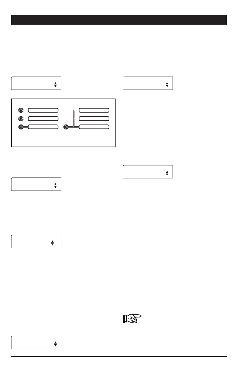
4.2.2. Independent Chain Disk Systems with a Common Auger
Independent Chain Disk Systems that share a
common bin auger are filled following the numerical order: the master Chain Disk System
is filled first, followed by Slave System #1,
Slave System #2, etc.
Chain Disk Systems Filling Order Controller & ID#
Bins
4.2.3. Independent Chain Disk Systems with Individual Augers
Independent Chain Disk Systems that all have
their own bin auger are being filled simultaneously when a feed cycle starts. Each Chain
Disk System filled according to its respective
parameter settings.
Chain Disk Systems Filling Order Controller & ID#
Refer to section 4.4.3 & 4.4.4 to get
information about the filling process
in this Chain Disk System setup.
Last
Third
Second
First
APCD-500-S
ID 3
APCD-500-S
ID 2
APCD-500-S
ID 1
APCD-500
MASTER
Refer to section 4.4.4 & 4.4.5 to get
information about the filling process
in this Chain Disk System setup.
Bins
Simultaneous
Simultaneous
Simultaneous
Simultaneous
APCD-500-S
ID 3
APCD-500-S
ID 2
APCD-500-S
ID 1
APCD-500
MASTER
APCD-500, rev10
9
Page 10
APCD-500
4.3. Feed Distribution Modes
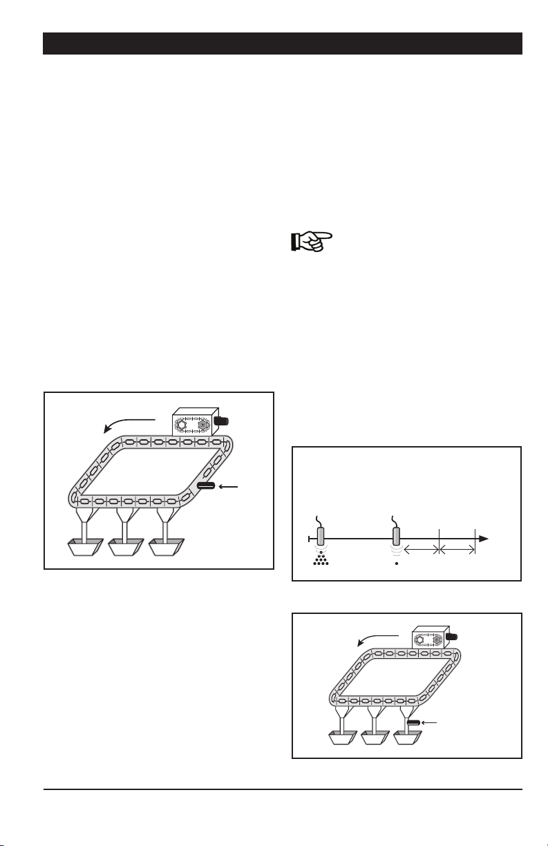
4.3.1. Timed Feed Distribution
When feed is distributed according to a timer,
the user chooses at what time the Chain Disk
Systems start being filled and at what time
feed starts being delivered to the animals. Up
to daily 25 feed cycles can be programmed.
Refer to section 5.6 to enable the timed feed
distribution method.
Location of the optional proximity
sensor in timer mode
When feed is distributed according to a timer,
a proximity sensor can be used to stop the
Chain Disk Systems when feed is detected
(see illustration). One proximity sensor must
be located at the end of each Chain Disk
System.
Drive unit
Proxy on
the Chain
Disk System
line after
the last
drop and
before the
Last drop
fill hopper
4.3.2. Continuous Feed Distribution
The continuous feed distribution mode
ensures the system is always full: the bin
auger starts bringing feed into the Chain
Disk System as soon as it gets empty. In
this operating mode, the proximity sensor
can either be mounted in the last drop or on
the Chain Disk System line after the last drop
and before the fill hopper.
Refer to section 5.6 to specify the
location of the proximity sensor.
Continuous Mode —
Proximity sensor in the last drop
If a proximity sensor is located in the last
drop of the Master Chain Disk System, the
system is considered as being full when the
proximity sensor detects feed. Once the
system is full, the controller waits for drop
tube to empty out before launching a new
feed cycle (the drop tubes are considered as
being empty when the proximity sensor stops
detecting feed).
Proxy in Last Drop
Feed is detected
by the master
proximity sensor
(the system is full)
A new feeding cycle
starts when feed stops
being detected by the
master proximity sensor
(the drop tube is empty)
Cont.
Bypass
Feeding
Delay
Delay
etc.
10
APCD-500, rev10
Drive unit
Proximity
sensor in
Last drop
drop
Page 11
APCD-500
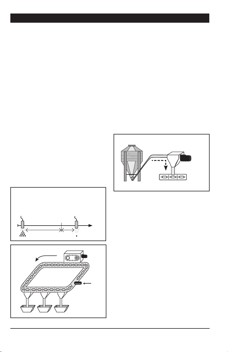
Continuous Mode —
Proximity sensor on the Chain Disk
System Line after the Last Drop
If the proximity sensor is located on the Chain
Disk System line af ter the last drop, the system
is considered as being full when the master
proximity sensor detects feed. At that moment, the controller launches the “Continuous
Feed Delay” (which represents the amount of
time required for the animals to eat the feed).
When the “Continuous Feed Delay” has elapsed,
all Chain Disk Systems start running again
during the “Feed Bypass Delay”.
a) If the master proximity sensor still detects
feed after the “Feed Bypass Delay”, the control-
ler relaunches the “Continuous Feed Delay” and
the “Feed Bypass Delay” again since the system
is not empty yet. This process is repeated
up until the master proximity sensor stops
detecting feed.
b) If no feed is detected in the master Chain
Disk System after the “Feed Bypass Delay”, the
controller restarts a new feed cycle in order
to refill the whole Chain Disk.
Proxy in Feed Line:
Feed is detected
by the master
proximity sensor
(the system is full)
The system is
empty when no feed
is detected after the
“Continuous Feed Delay”
+ “Feed Bypass Delay”.
A new feeding cycle
then starts.
4.4. Filling Process
Operation of the Bin Auger:
At the start-up of each feeding cycle, right
after the Auger’s Delay has elapsed, the bin
auger starts bringing feed into the Chain Disk
Systems and stops when the Chain Disk System is full. There are two ways the controller
can detect that a Chain Disk System is full:
1. The proximity sensor detects feed for
5 seconds without interruption;
2. The drive unit has been running for the
“Max Run Time” parameter value (only if no
proximity sensor is used).
Bin
Auger
Feed Line
Chain Disk Overload Protection:
The controller monitors the amperage draw of
Chain Disk drive units to prevent overloading
the system:
Auger
Motor
Continuous Feeding
Delay
Last drop
Bypass
Delay
Drive unit
Proximity
sensor on
the Chain
Disk System
line after
the last
drop
•Ifthe amperageexceeds the limit “Max
Current Consumption” limit, the controller
temporarily shuts down the bin auger
while the Chain Disk keeps running in
order to discharge the feed. As the feed
load decreases the amperage draw also
decreases; the bin auger restarts when
the current consumption gets lower than
the “Max Cur rent Consum ption - Window Size”.
•Iftheamperagedrawgetshigherthan
the “Critical Current Consumption” for more
than the “Cr iti cal Del ay”, the system stops
and will not restart.
APCD-500, rev10
11
Page 12
APCD-500
Refer to section 5.6 to set the bin
auger parameters
NOTE: The whole Chain Disk stops
running when an alarm is active!
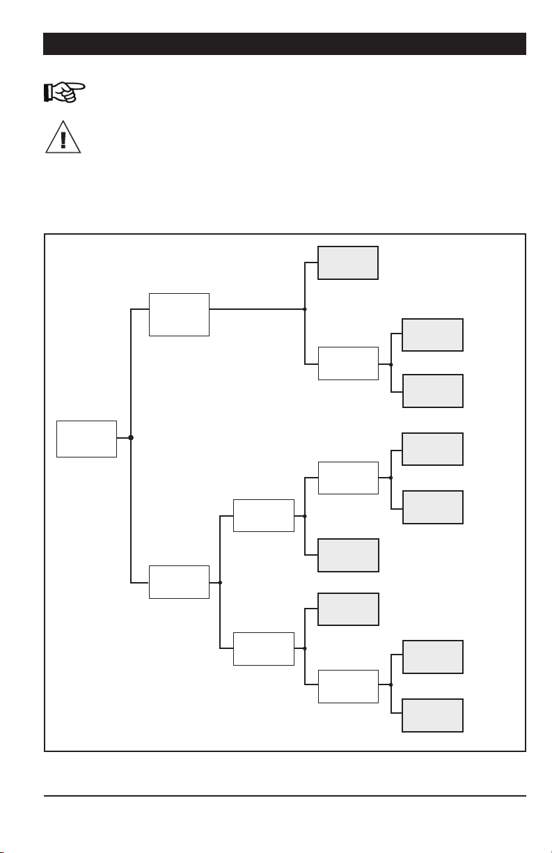
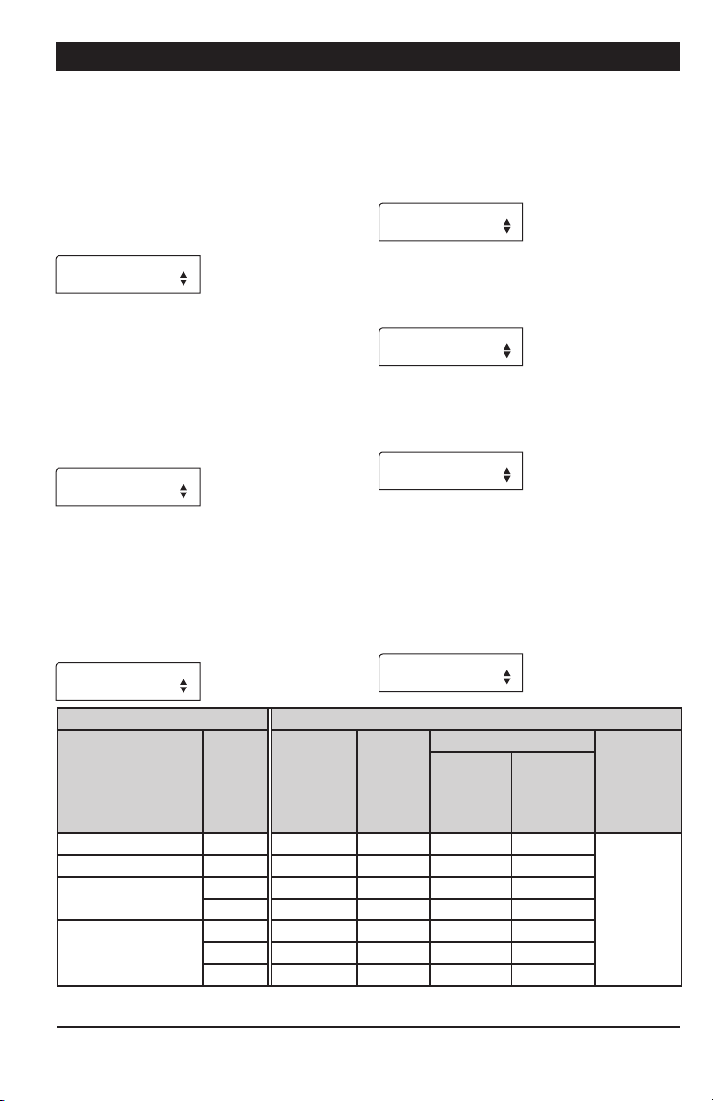
Cascaded
Chain Disk
System
Type of
Chain Disk
System
Common
Bin Auger
Filling Process According to the
System Setup:
The filling process of Chain Disk System depends on your particular system setup. Locate
your par ticular application setup on the hierarchy
tree below and then refer to the proper section of
the manual to get explanations about the filling
process of the chosen option.
Continuous
Feeding
Timed
Feeding
Timed
Feeding
Sec. 4.4.1,
& Graph A
With
proximity
sensor
Without
proximity
sensor
With
proximity
sensor
Without
proximity
sensor
Sec. 4.4.2,
&
Graph B
Sec. 4.4.2,
& Graph C
Sec. 4.4.4
& Graph E
Sec. 4.4.4
& Graph F
12
Independent
Chain Disk
System
APCD-500, rev10
Individual
Bin Augers
Continuous
Feeding
Continuous
Feeding
Timed
Feeding
Sec. 4.4.3
& Graph D
Sec. 4.4.5
& Graph G
With
proximity
sensor
Without
proximity
sensor
Sec. 4.4.6
& Graph H
Sec. 4.4.6
& Graph I
Possible Chain Disk Setup
Page 13
APCD-500
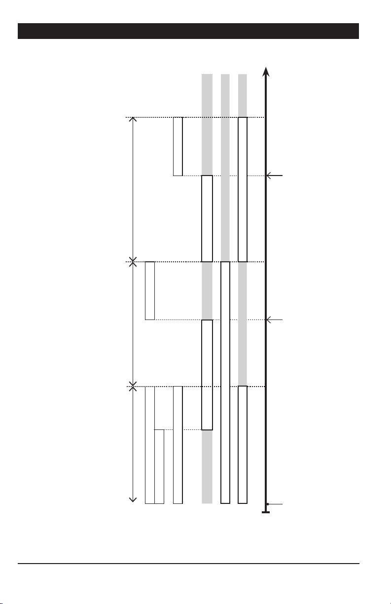
4.4.1. Filling Cascaded Chain Disk Systems with Continuous Feed Distribution Mode
1. Beginning the Filling Process — The fill -
ing process starts at the end of the previous
cycle (refer to point 7 below to see when a
cycle ends).
2. Emptying the Chain Disk Systems —
When the “Continuous Delay” has elapsed,
the controller activates all drive units during
the “Auge r D e l a y” to make sure all Chain Disk
Systems are empty before bringing new feed.
3. Filling the Farthest Chain Disk System —
When the “Auger De l a y” has elapsed, all drive
units keep running and the bin auger starts
bringing feed into the Chain Disk Systems.
The feed travels through all empty Chain Disk
Systems in order to reach the farthest empty
Chain Disk System (i.e, the Chain Disk with
the highest ID number).
4. The Farthest Chain Disk System is Full
— The controller knows the farthest Chain
Disk System is full when its proximity sensor
detects feed for 5 seconds without interruption. When feed is detected in the farthest
Chain Disk System, its drive unit stops and
all other Chain Disk Systems keep on running.
5. Filling the Chain Disk Systems One by One
— Each time a Chain Disk System gets full,
its drive unit stops running and the previous
Chain Disk System starts being filled.
6. The Last Chain Disk System is Full — When
the master Chain Disk System is full (last Chain
Disk System) all drive units are off and the bin
auger stops bringing feed into the system.
7. Next cycle — The next feed cycle starts
when the master Chain Disk System gets
empty:
a) If the proximity sensor is mounted in the
last drop, the next cycle starts when the
proximity sensor stops detecting feed.
b) If the proximity sensor is located at the
end of the Master Chain Disk System, the
new cycle starts if no feed is detected
after 2 delays: “Continuous Feed Delay” +
“Bypass Delay” (the “Continuous Feed Delay
is the amount of time required for the
animals to eat the feed).
Back to step 1.
Bins
Chain Disk Systems Filling Order Controller & ID#
Last
Third
Second
First
APCD-500
MASTER
APCD-500-S
ID 1
APCD-500-S
ID 2
APCD-500-S
ID 3
APCD-500, rev10
13
Page 14
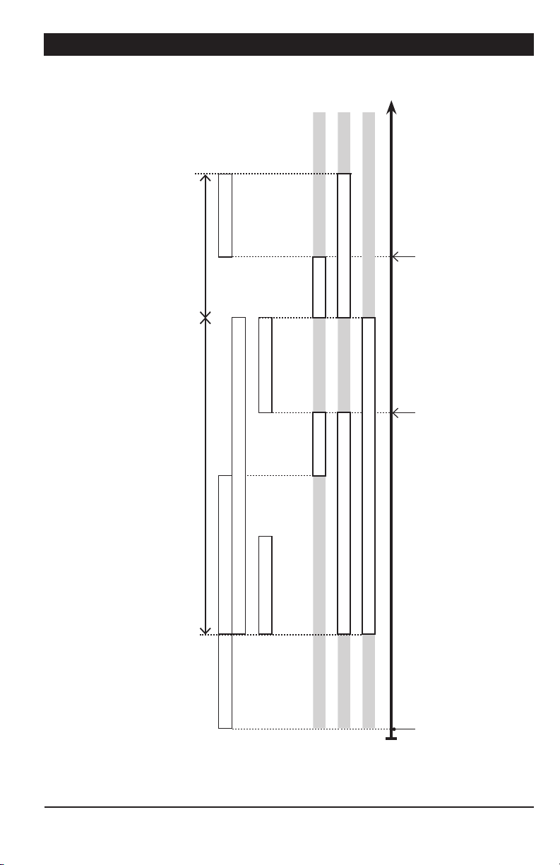
APCD-500
Time
The proximity sensor in the
Maste r Chain Disk System
being filled
Master Chain D isk Syste m is
detects feed for 5 seconds
The proximity sensor in the
slave’s Chain Disk System
detects feed for 5 seconds
14
GRAPH A
Chain Disk Setup : Cascaded Chain Disk Systems
Feed Distribution Mode : Continuous
Proximity sensor? : Yes
APCD-500, rev10
OFF ON OFF ON OFF
farthest one
filled in turn s, star ting with the
Slave Chain Disk Systems are bein g
(MA) Feed bypass delay (automatically dened by the controller)
(SL) Feed bypass delay (SL) Shutdown delay
OFF ON OFF ON OFF
OFF ON OFF
Continuous feed delay (MA) Auger delay (MA) Shutdown delay
APCD-500
Parameters
Status
Status
Bin Au ger
Status
Mstr C hainD
Slave C hainD
A new feed cycle sta rts
The master proximity stops detecting feed
(if proxy is in the drop)orRight after the end of the previou s cycle
(if proxy is on the Chain Disk System line
after the last drop).
Page 15

APCD-500
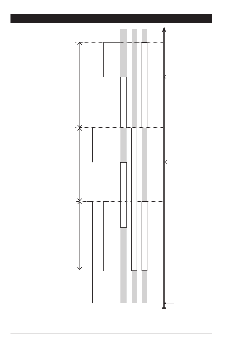
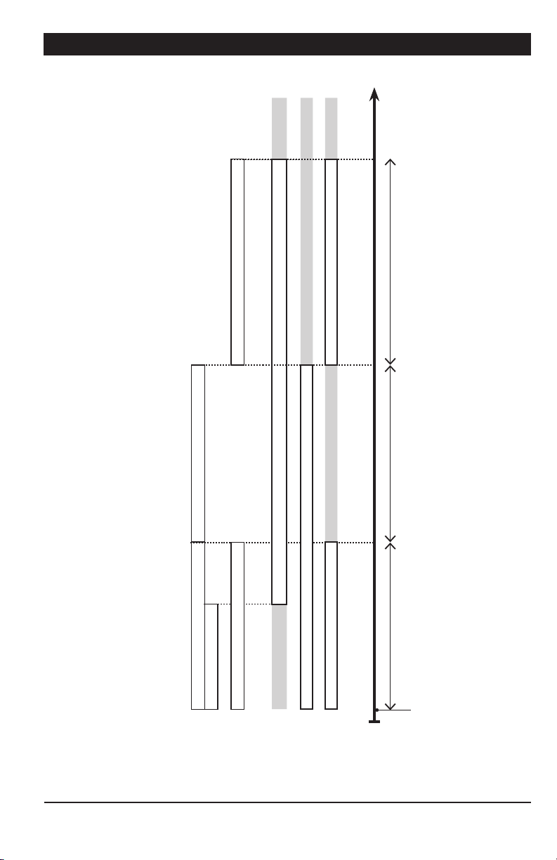
4.4.2. Filling Cascaded Chain Disk Systems with Timer Mode
1. Beginning the Filling Process — The filling
process starts at the start-up of a feed cycle
(defined by the “C yc le Time” parameter).
2. Cleaning the Drops — If actuators are
used and the “C le an Dro p” option is enabled
in the INSTALLATION menu, the controller
opens and closes the drops 3 times in a row
to evacuate feed leftovers from the system.
3. Empt ying the Chain Disk Systems — To
ensure all Chain Disk Systems are empty
before bringing new feed, the controller activates all drive units during the “Auger De l a y” .
4. Filling the Farthest Chain Disk System —
When the “Auger De l a y” has elapsed, all drive
units keep running and the bin auger starts
bringing feed into the Chain Disk Systems.
The feed travels through all empty Chain
Disk Systems in order to reach the farthest
empty System (i.e., the Chain Disk with the
highest ID number).
5. The Far thest Chain Disk System is Full
• If a proximity se nsor is use d: the controller knows the Chain Disk System is full
when the proximity sensor detects feed
for 5 seconds. When feed is detected,
the controller stops the feed entry (bin
auger), and stops all other drive units; the
drive unit of the full Chain Disk System
keeps running for the “Shutdown Delay”
and then stops.
• If no proximity sensor is used: if no
proximity sensor is used, the controller
knows the farthest Chain Disk System
is full when the drive unit of this Chain
Disk System has been running for its
respective “Run Time”. The drive unit of
this Chain Disk System stops when its
“Run Time” has elapsed.
6. Filling the Next Chain Disk System —
When the loaded Chain Disk System stops,
the drive units of all empty Chain Disk Systems restart, and feed enters once again into
the feed lines. Steps 4 and 5 are repeated up
until all Chain Disk Systems are full.
7. Feed Dumping — When the Chain Disk system is fully full, feed is ready to be delivered
to the animals. Step to section 4.4.
Bins
Chain Disk Systems Filling Order Controller & ID#
Last
Third
Second
First
APCD-500
MASTER
APCD-500-S
ID 1
APCD-500-S
ID 2
APCD-500-S
ID 3
APCD-500, rev10
15
Page 16

APCD-500
Time
The proximity sensor on
the Master Chain Disk
System line after the last
drop detects feed for
5 seconds
being filled
The Ma ster Cha in Disk Sy stem is
The same process is
repeated to fill the next
slave Chain Disk System
(if applicable)
16
GRAPH B
Chain Disk Setup : Cascaded Chain Disk Systems
Feed Distribution Mode : Timer
Proximity sensor? : Yes
APCD-500, rev10
on the slave Chain
feed for 5 seconds
the las t drop detects
The proximity sensor
Disk System line after
farthest one
filled in turn s, star ting wit h the
Slave Chain Disk Systems are bein g
(MA) Auger delay (MA) Shutdown delay
(MA) Feed bypass delay (automatically dened by the controller)
APCD-500
Parameters
(SL) Feed bypass delay (SL) Shutdown delay
OFF ON OFF ON OFF
ON OFF ON OFF
ON OFF
Status
Status
Bin Au ger
Status
Mstr C hainD
Slave C hainD
A new feed cycle sta rts
(Cycle Time i s reached)
Page 17

APCD-500
Time
being filled
The Ma ster Cha in Disk Sy stem is
The same process is repeated to fill
the next slave Chain Disk Sys tem
(if applicable)
GRAPH C
farthest one
filled in turn s, star ting wit h the
Slave Chain Disk Systems are bein g
(MA) Auger delay (MA) Run time
(SL) Run Time
APCD-500
Chain Disk Setup : Cascaded Chain Disk Systems
Feed Distribution Mode : Timer
Proximity sensor? : No
Parameters
OFF ON OFF
ON OFF
ON OFF
Status
Status
Bin Au ger
Status
Mstr C hainD
Slave C hainD
A feed cycle star ts
APCD-500, rev10
17
Page 18

APCD-500
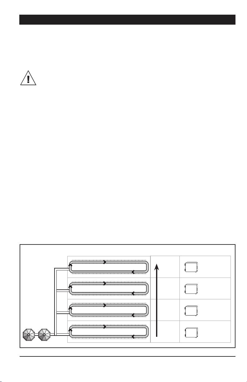
4.4.3. Filling Independent Chain Disk
Systems with a Common Bin Auger using Continuous Feed Distribution Mode
The common bin auger must be connected to the master APCD module!
1. Beginning the Filling Process — The fill -
ing process starts at the end of the previous
cycle (refer to point 7 below to see when a
cycle ends).
2. Emptying the Bin Auger and Chain Disk
Systems — When the “Continuous Delay” has
elapsed, the controller activates all drive
units during the “Purge Time” and launches
the “Au g er D el a y” . When the “Au g er D e l ay ” has
elapsed, the bin auger starts sending feed towards the Chain Disk Systems. Normally, the
“Purge Time” must be longer than the “Au g e r
De la y” to prevent feed from accumulating at
the end of the bin auger.
3. Filling the First Chain Disk System —
When the “Purge Time” is over, all drive units
stop except for the first Chain Disk System
to be filled: the master Chain Disk System.
4. The Chain Disk System is Full — The
controller knows the Chain Disk System is
full when the proximity sensor located at its
end detects feed for 5 seconds without interruption. When feed is detected, the drive unit
of this Chain Disk System stops.
5. Filling the Chain Disk Systems One by One
— Each time a Chain Disk System gets full, its
drive unit stops running and the next Chain
Disk System star ts being filled (Chain Disk
Systems are being filled in numerical order).
6. The Last Chain Disk System is Full — When
the last Chain Disk System is full (i.e., the
slave Chain Disk with the highest ID #), all
drive units are off and the bin auger stops
bringing feed into the system.
7. Next cycle — The next feed cycle starts
when the last Chain Disk System gets empty:
a) If the proximity sensor is mounted in the
last drop, the next cycle starts when the
proximity sensor stops detecting feed.
b) If the proximity sensor is on the Master Chain Disk System line after the last
drop, the new cycle starts if no feed is
detected after 2 delays: “Continuous Feed
Delay” + “Bypass Delay” (the “Continuous
Feed Delay is the amount of time required
for the animals to eat the feed).
Back to step 1.
18
Bins
Chain Disk Systems Filling Order Controller & ID#
APCD-500, rev10
Last
Third
Second
First
APCD-500-S
ID 3
APCD-500-S
ID 2
APCD-500-S
ID 1
APCD-500
MASTER
Page 19
APCD-500
Time
The proximity sensor
on the Slave Chain Disk
System detects feed for
5 seconds
Slave Chain Disk
System being filled
The proximity sensor on
the Master Chain Disk
System detects feed for
5 seconds
GRAPH D
Master Chain Disk
System being filled
Purge Cycle
(MA) Auger delay
(SL) Purge time (slave’s proxy is bypassed) (SL) Shutdown delay
Cont. feed delay (MA) Purge time (master proxy is bypassed) (MA) Shutdown delay
Chain Disk Setup : Independent Chain Disk Systems
Bin Auger Setup : Common auger
Feed Distribution Mode : Continuous
Proximity sensor? : With proximity sensor
APCD-500
Parameters
OFF ON OFF ON OFF
OFF ON OFF
OFF ON OFF ON OFF
A new feed cycle sta rts
The master proximity stops detecting feed
(if proxy is in the drop)orRight after the end of the previou s cycle
(if proxy is on the Master Chain Disk
Status
Status
Bin Au ger
Status
Mstr C hainD
Slave C hainD
APCD-500, rev10
System line after the last drop).
19
Page 20
APCD-500
4.4.4. Filling Independent Chain
Disk Systems with a Common Bin
Auger using Timer Mode
The common bin auger must be connected to the master APCD module!
1. Beginning the Filling Process — The filling
process starts at the start-up of a feed cycle
(defined by the “C yc le Time” parameter).
2. Cleaning the Drops — If actuators are
used and the “C le an Dro p” option is enabled
in the INSTALLATION menu, the controller
opens and closes the drops 3 times in a row
to evacuate feed leftovers from the system.
3. Empt ying the Bin Auger and Chain Disk
Systems — To ensure the bin auger and Chain
Disk Systems are empty before bringing new
feed, the controller activates all drive units
during the “Purge Ti me” and launches the
“A u ge r D e l a y”. When the “A u g e r D e l a y ” has
elapsed, the bin auger starts sending feed towards the Chain Disk Systems. Normally, the
“Purge Time” must be longer than the “Au g e r
De la y” to prevent feed from accumulating at
the end of the bin auger.
4. Filling the First Chain Disk System —
When the “Purge Time” is over, all drive units
stop except for the first Chain Disk System
to be filled: the master Chain Disk System.
5. The Chain Disk System is Full:
• If a proximity sensor is used: the controller knows the Chain Disk System is full
when the proximity sensor detects feed
for 5 seconds. When feed is detected,
the controller stops the feed entry (bin
auger) and the drive unit of the loaded
Chain Disk System keeps running for the
“Shutdown Delay” and then stops.
• If no proximity sensor is used:
The controller knows the Chain Disk
System is full when the drive unit has
been running for its respective “R un T ime”
parameter value. The drive unit of this
Chain Disk System stops when its “Run
Ti me” has elapsed.
6. Loading Next Chain Disk System — When
the loaded Chain Disk System stops, the next
empty Chain Disk System starts running and
the bin auger starts sending feed towards
this Chain Disk System. Steps 4 and 5 are repeated up until all Chain Disk Systems are full.
7. Feed Dumping — When the Chain Disk
system is fully loaded, feed is ready to be de livered to the animals. Step to section 4.4.
20
Bins
Chain Disk Systems Filling Order Controller & ID#
APCD-500, rev10
Last
Third
Second
First
APCD-500-S
ID 3
APCD-500-S
ID 2
APCD-500-S
ID 1
APCD-500
MASTER
Page 21
APCD-500
Time
The proximity sensor
on the Slave Chain Disk
System detects feed for
5 seconds
Slave Chain Disk
System being filled
GRAPH E
The proximity sensor on
the Master Chain Disk
System detects feed for
5 seconds
Master Chain Disk System
being filled
Purge Cycle
(MA) Purge time (master proxy is bypassed) (MA) Shutdown delay
(MA) Auger delay
(SL) Purge time (slave’s proxy is bypassed) (SL) Shutdown delay
OFF ON OFF ON OFF
ON OFF
ON OFF ON OFF
Status
Status
Chain Disk Setup : Independent Chain Disk Systems
Bin Auger Setup : Common auger
Feed Distribution Mode : Timer
Proximity sensor? : Yes
APCD-500
Parameters
Bin Au ger
Status
Mstr C hainD
Slave C hainD
A feed cycle star ts
(Cycle Time is reached)
APCD-500, rev10
21
Page 22
APCD-500
Time
Slave Chain Disk
Systems being filled
22
GRAPH F
Chain Disk Setup : Independent Chain Disk Systems
Bin Auger Setup : Common auger
APCD-500, rev10
System being filled
Purge Cycle Master Chain Disk
(MA) Purge time (MA) Run time
(MA) Auger delay
(SL) Purge time (SL) Run time
OFF ON OFF
ON OFF
ON OFF ON OFF
Status
Status
Feed Distribution Mode : Timer
Proximity sensor? : No, a Run Time is used to stop the Chain Disk System
APCD-500
Parameters
Bin Au ger
Status
Mstr C hainD
Slave C hainD
A feed cycle star ts
(Cycle Time is reached)
Page 23
APCD-500
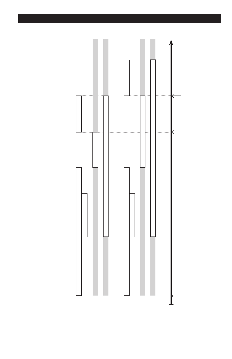
4.4.5. Filling Independent Chain
Disk Systems with Individual Bin Augers Using Continuous Feed Distribution Mode
1. Beginning the Filling Process — The fill -
ing process starts at the end of the previous
cycle (refer to point 6 below to see when a
cycle ends).
2. Emptying the Chain Disk Systems —
When the “Continuous Delay” has elapsed,
the controller activates all drive units during
their respective “Auger Delay” to make sure
all Chain Disk Systems are empty before
bringing new feed.
3. Filling Chain Disk Systems — When the
“A u ge r D e l a y” of a Chain Disk System has
elapsed, all Chain Disk Systems keep running and start being filled by their respective
bin auger.
4. A Chain Disk System is Full — The controller knows a Chain Disk System is full
when the proximity sensor detects feed for
5 seconds without interruption. When a Chain
Disk System is full, its respective drive unit
and bin auger stop running.
5. All Chain Disk Systems are Full — When
the last Chain Disk System is full, all drive
units are off and the bin auger stops bringing
feed into the Chain Disk System.
6. Next cycle — The next feed cycle starts
when the master Chain Disk System gets
empty:
a) If the proximity sensor is mounted in the
last drop, the next cycle starts when the
proximity sensor stops detecting feed.
b) If the proximity sensor is located on the
Master Chain Disk System line after the
last drop, the new cycle starts if no feed is
detected after these 2 delays: “Continuous
Feed Delay” + “Bypa ss Delay” (the “Continuous
Feed Delay i s the amount of time required for
the animals to eat the feed).
Back to step 1.
Bins
Chain Disk Systems Filling Order Controller & ID#
Simultaneous
Simultaneous
Simultaneous
Simultaneous
APCD-500, rev10
APCD-500-S
ID 3
APCD-500-S
ID 2
APCD-500-S
ID 1
APCD-500
MASTER
23
Page 24
APCD-500
Time
The slave’s proximity
sensor detects feed for
5 seconds
The master’s proximity
sensor detects feed for
5 seconds
24
GRAPH G
Chain Disk Setup : Independent Chain Disk Systems
Bin Auger Setup : Individual augers
Feed Distribution Mode : Continuous
Proximity sensor? : Yes
APCD-500, rev10
(MA) Feed bypass delay
(MA) Continuous feeding delay (MA) Auger delay (MA) Shutdown delay
OFF ON OFF
Status
APCD-500
Parameters
Mstr C hainD
Mast er Bin Aug er
OFF ON OFF
Status
(SL) Feed bypass delay
(SL) Continuous feeding delay (SL) Auger delay (SL) Shutdown delay
OFF ON OFF
Slave B in
APCD-500
Parameters
Auger Status
Slave C hainD
OFF ON OFF
Status
A new feed cycle sta rts
The master proximity stops detecting feed
(if proxy is in the drop)orRight after the end of the previou s cycle
(if proxy is on the Master Chain Disk S ystem
line after the last drop).
Page 25
APCD-500
4.4.6. Filling Independent Chain
Disk Systems with Individual Bin Augers Using the Timed Feed Distribution Mode
1. Beginning the Filling Process — The filling
process starts at the start-up of a feed cycle
(defined by the “C yc le Time” parameter).
2. Cleaning the Drops — If actuators are
used and the “C le an Dro p” option is enabled
in the INSTALLATION menu, the controller
opens and closes the drops 3 times in a row
to evacuate feed leftovers from the system.
3. Empt ying Chain Disk Systems — To ensure all Chain Disk Systems are empty before
bringing new feed, the controller activates
all drive units during their respective “Au g e r
De la y”.
4. Filling Chain Disk Systems — When the
“A u ge r D e l a y” of a Chain Disk System has
elapsed, the Chain Disk System keeps running
and its respective bin auger starts sending
feed towards this Chain Disk System.
5. The Chain Disk System is Full:
• If a proximity sensor is used:
The controller knows a Chain Disk System
is full when the proximity sensor detects
feed for 5 seconds. When feed is detected, the controller stops the feed entry (bin
auger) and the drive unit keeps running
for the “Shutdown Delay” and then stops.
• If no proximity sensor is used:
The controller knows the Chain Disk
System is full when the drive unit has
been running for its respective “R un T ime”
parameter value. The drive unit of this
Chain Disk System stops when its “Run
Ti me” has elapsed.
6. Feed Dumping — When the Chain Disk
system is full, feed is ready to be delivered
to the animals. Step to section 4.4.
Chain Disk Systems Filling Order Controller & ID#
Simultaneous
Simultaneous
Simultaneous
Simultaneous
APCD-500, rev10
APCD-500-S
ID 3
APCD-500-S
ID 2
APCD-500-S
ID 1
APCD-500
MASTER
25
Page 26

APCD-500
Time
The slave’s proximity
sensor detects feed for
5 seconds
26
GRAPH H
Chain Disk Setup : Independent Chain Disk Systems
Bin Auger Setup : Individual augers
Feed Distribution Mode : Timer
APCD-500, rev10
The master’s proximity
sensor detects feed for
5 seconds
(MA) Auger Delay (MA) Shutdown delay
(MA) Feed bypass delay
OFF ON OFF
ON OFF
Status
Status
APCD-500
Proximity sensor? : Yes
Parameters
Mstr C hainD
Mast er Bin Aug er
(SL) Auger Delay (SL) Shutdown delay
(SL) Feed bypass delay
OFF ON OFF
Slave B in
APCD-500
Parameters
Auger Status
Slave C hainD
ON OFF
Status
A feed cycle star ts
(Cycle Time is reached)
Page 27

APCD-500
Time
GRAPH I
(Master) Run Time
(Master) Auger Delay
OFF ON OFF
INDEPENDENT MODE, INDIVIDUAL AUGER, WITH TIMER
APCD-500
Chain Disk Setup : Independent Chain Disk Systems
Bin Auger Setup : Individual augers
Feed Distribution Mode : Timer
Proximity sensor? : No
Parameters
ON OFF
Status
Status
Mstr C hainD
Mast er Bin Aug er
(Slave) Run Time
(Slave) Auger Delay
OFF ON OFF
Slave’s B in
APCD-500
Parameters
Auger Status
ON OFF
Status
Slave C hainD
APCD-500, rev10
A feed cycle star ts
(Cycle Time is reached)
27
Page 28

APCD-500
4.5. Feed Delivery Process
After the Chain Disk Systems have been
filled up, feed is ready to be delivered to
the animals. This section explains how feed
is dumped by actuators and air valves and
how it is being delivered when no actuator/
air valve is used. Note that the actuators and
air valves can only be used with the timerbased feed distribution mode and note that
their parameters are common to all Chain Disk
Systems in use.
Feed Delivery using Actuators:
1. The actuator opens the drops during the
opening time.
2. When the opening time has elapsed, the
actuator stops moving during the “A c t u at or /A .
Valve Delay”;
3. When the “Actuator/A.Valve Delay” ha s
elapsed, the actuator fully closes the drops
during twice the opening time or until its
security switch is reached.
4. End of the feed cycle.
Feed Delivery with Air Valves:
1. The air valve make the dumps open at the
“Dump Time”;
2. The dumps remain opened during the
“Actuator/A.Valve Delay”;
3. The air valve make the dumps close after
the “Actuator/A.Valve Delay” has elapsed.
4. End of the feed cycle.
4.6. Feed Cycle
When the feed distribution is done in timer
mode, the user must specify the moment at
which the Chain Disk Systems must be filled
and the time at which feed must be delivered
to the animals. Up to 25 feed cycles can be
performed each day. Refer to section 5.6 to
enable the required number of cycles.
Feed Cycle Start Time:
This is the time at which each feed cycle
starts.
The controller automatically adjusts
the time at which the feed cycles
start and the number of feed cycles
in case of a programming error (i.e. if
the feed cycles overlap one another
or if they exceed 24 hours).
Dump Time:
If actuators or air valves are used, set the
time at which the dumps must open. Make
sure this dump is performed when all the
Chain Disk Systems are full. The dump time
should be higher than the “Start time + Ma x
Ru n Ti me” of all Chain Disk Systems otherwise
the controller will automatically redefine this
time setting.
Run Time:
If no proximity sensor is used, a run time must
be defined. This value represents the amount
of time that is required to fill-up each Chain
Disk System.
Feed Delivery without Actuators &
Valves:
If no actuator or air valve is used, all feed that
enters into Chain Disk Systems directly falls
in the feeders while the Chain Disk Systems
are being filled. When they are full, the feed
gradually decreases in the feeders as the
animals eat.
28
APCD-500, rev10
Page 29

APCD-500
5. PARAMETER SETTINGS
5.1. Controller Status
The STATUS menu shows the ongoing operations of the controller. All alarms situations
must also be acknowledged from this menu
(refer to section 5.7 for further information
about alarms). The controller automatically
returns to this S TATU S menu after 4 minutes
of inactivity.
The S TATU S menu tells you:
• if the test mode is active;
• if the manual mode is active;
• when the next feeding cycle will start;
• when the drive units will stop (Shut Down
Delay);
• when the actuator will stop moving;
• when the Actuator Delay ends.
• when the Purge Time ends.
• when the next dump will be performed;
• what is the amperage draw of each drive
unit;
1. Use the menu select buttons to select the
STAT US main menu.
2. Use the arrow keys to scroll the display.
5.2. Run Time History
The controller has an history menu in which
the daily run time of the Chain Disk Systems
(master and Slave Chain Disk Systems) are
logged in for the past 5 days.
1. Use the menu select buttons to select the
RUN TIME HISTORY menu.
Run Time Index
Mastr
2. Press MODIFY then use the arrow keys to
select the desired Chain Disk System (Mstr
= master, S#x = slave #x (AP CD-500S #x)
Run Time Index
- S #1
3. Press MODIFY once again to access the
run time status information of the selected
Chain Disk System (Master or Slave). If the
Chain Disk System is feeding, the current
cycle will be displayed along with the mode
(manual or automatic), and the duration of
the run time.
Current Cycle S1/M
(MANUAL) 0:35
If the Chain Disk System is not feeding, the
last cycle will be displayed along with the
mode (manual or automatic) it was in, and
the duration of the run time.
Last Cycle S1/M
(AUTO) 0:35
4. Use the down-arrow key to scroll the
display. The daily run times of the selected
Chain Disk System are displayed for the past
5 days.
Run Time Hist S1
Today 1:20
APCD-500, rev10
29
Page 30

APCD-500
5.3. Time & Date
1. Use the menu select buttons to select the
TIME / DATE menu. The current time and
date are displayed.
12:00:00PM
01/01/200X
2. Press MODIFY. The hours flash on the
display. Use the arrow keys to set them to
the proper value.
3. Press MODIFY once again. The minutes
flash on the display. Use the arrow keys to
set them to the proper value.
4. Press MODIFY once again. The seconds
flash on the display. Use the arrow keys to
set the seconds to the proper value.
5. Press MODIFY then proceed in similar
fashion to set the date (dd/mm/yyyy).
5.3.1. Adjusting Improper System
Time
When the notification message that follows is
displayed onscreen you must set the correct
time and date.
Improper System Time
Set Time & Date
CAUTION: To ensure accurate feed
data, history logs, and other important
system information, you must set
the correct time and date whenever
prompted.
To adjust the time and date when the “Improper System Time” notification appears,
follow the steps in section “5.3. Time &
Date”.
Once the time and date has been adjusted,
the notification message disappears, the system clock is set, and accurate data is ensured.
Note: The notification message repeatedly disappears and reappears
until the time and date are set.
5.4. Feed Cycle Settings
Refer to section 4.5 & 4.6 to get information
on the feed cycles. In addition, a feed cycle
worksheet is available to make it easier for
you to program your feed cycles (see next
page).
1. Use the menu select buttons to select the
FEED CYCLES menu. *This menu is only avail-
able if feed is distributed according to a timer (the
continuous feeding mode is disabled in the installation). A password may also be required to access
this menu (see sec. 5.6).
FeedingCycle 1
Start At 6:12A
2. Press MODIFY. The start time of the first
feed cycle flashes on the display. Use the
arrow keys to adjust it to the proper value.
Press MODIF Y once again to validate.
3. Press the down-arrow key once. The dump
time of the first feed cycle is displayed. * This
parameter is available if actuators or air valves are
enabled (see sec. 5.6).
4. Press MODIFY. The dump time of the first
feed cycle flashes on the display. Use the
arrow keys to adjust it to the proper value.
Press MODIF Y once again to validate the
new value.
5. Press the down-arrow key once. The start
time of the second feed cycle is displayed.
Proceed in similar fashion to set the start and
dump times of all feed cycles in use.
Check Feed Cycles : The controller
automatically re-arranges the feed
cycles in the case of a programming
error. The warning message “Check
Feed Cycles” is displayed in that case.
The user has to validate the new feed
cycle order by scrolling down the
whole feed cycle menu. The warning
message will then disappear.
30
APCD-500, rev10
Page 31

APCD-500
Chain Disk System Cycle Worksheet
Feed
Start
Cycles
Time
1
Master
Chain
Disk
09:00A 01:30 00:30 00:30 n.u. n.u. n.u. n.u. n.u. 11:30A 11:45A
Ex.
Cycle 1
__:__ __:__ __:__ __:__ __:__ __:__ __:__ __:__ __:__ __:__ __:__
Cycle 2
__:__ __:__ __:__ __:__ __:__ __:__ __:__ __:__ __:__ __:__ __:__
Cycle 3
__:__ __:__ __:__ __:__ __:__ __:__ __:__ __:__ __:__ __:__ __:__
Cycle 4
__:__ __:__ __:__ __:__ __:__ __:__ __:__ __:__ __:__ __:__ __:__
Cycle 5
__:__ __:__ __:__ __:__ __:__ __:__ __:__ __:__ __:__ __:__ __:__
Cycle 6
__:__ __:__ __:__ __:__ __:__ __:__ __:__ __:__ __:__ __:__ __:__
Cycle 7
__:__ __:__ __:__ __:__ __:__ __:__ __:__ __:__ __:__ __:__ __:__
Cycle 8
__:__ __:__ __:__ __:__ __:__ __:__ __:__ __:__ __:__ __:__ __:__
Cycle 9
__:__ __:__ __:__ __:__ __:__ __:__ __:__ __:__ __:__ __:__ __:__
Cyc.10
__:__ __:__ __:__ __:__ __:__ __:__ __:__ __:__ __:__ __:__ __:__
Cyc.11
__:__ __:__ __:__ __:__ __:__ __:__ __:__ __:__ __:__ __:__ __:__
Cyc.12
__:__ __:__ __:__ __:__ __:__ __:__ __:__ __:__ __:__ __:__ __:__
Cyc.13
__:__ __:__ __:__ __:__ __:__ __:__ __:__ __:__ __:__ __:__ __:__
Cyc.14
__:__ __:__ __:__ __:__ __:__ __:__ __:__ __:__ __:__ __:__ __:__
Cyc.15
__:__ __:__ __:__ __:__ __:__ __:__ __:__ __:__ __:__ __:__ __:__
Cyc.16
__:__ __:__ __:__ __:__ __:__ __:__ __:__ __:__ __:__ __:__ __:__
Cyc.17
__:__ __:__ __:__ __:__ __:__ __:__ __:__ __:__ __:__ __:__ __:__
Cyc.18
__:__ __:__ __:__ __:__ __:__ __:__ __:__ __:__ __:__ __:__ __:__
Cyc.19
__:__ __:__ __:__ __:__ __:__ __:__ __:__ __:__ __:__ __:__ __:__
Cyc.20
__:__ __:__ __:__ __:__ __:__ __:__ __:__ __:__ __:__ __:__ __:__
Cyc.21
__:__ __:__ __:__ __:__ __:__ __:__ __:__ __:__ __:__ __:__ __:__
Cyc.22
__:__ __:__ __:__ __:__ __:__ __:__ __:__ __:__ __:__ __:__ __:__
Cyc.23
__:__ __:__ __:__ __:__ __:__ __:__ __:__ __:__ __:__ __:__ __:__
Cyc.24
__:__ __:__ __:__ __:__ __:__ __:__ __:__ __:__ __:__ __:__ __:__
Cyc.25
__:__ __:__ __:__ __:__ __:__ __:__ __:__ __:__ __:__ __:__ __:__
Chain Disk System’s Maximum Run Time
Slave
Slave
Chain
Disk 2
Slave
Chain
Disk 3
Chain
Disk 1
Slave
Chain
Disk 4
Slave
Chain
Disk 5
2
Slave
Chain
Disk 6
Slave
Chain
Disk 7
Full
3
at
Dump
Time
4
1. The “Start Time” of a cycle cannot overlap the cycle that preceeds (a cycle ends at its respec tive “Start
Time” + “Max Run Time” + “Dump Time (if applicable)”.
2. The “Maximum Run Time” parameter value is common to all feed cycles.
3. The time at which all Chain Disk Systems are full corresponds to the “Start Time” + “Max Run Time” of
all Chain Disk Systems.
4. Make sure the dump is performed after all Chain Disk Systems are full. The “Dump Time” must only be
defined if actuators or air valves are enabled.
APCD-500, rev10
31
Page 32

APCD-500
5.5. Run Time Settings
The run time parameter represents the time
that is required to fill-up each Chain Disk
System. It ranges from 00:01 hh:mm to
03:59 hh:mm. Refer to section 4.5 to get
information about this parameter.
1. Use the menu select buttons to select the
FEED CYCLES menu. *This menu is available if
feed is distributed according to a timer (i.e., the continuous feeding mode is disabled in the installation)
and if no proximity sensor is used. A password may
also be required to access this menu (see sec. 5.6)).
2. Press the down-arrow key in order to select
the first run time screen display. This is the
“Run Time” of the master Chain Disk System.
Chain Disk Mstr
Run Time 1:30h:m
3. Press MODIFY and then use the arrow keys
to set this parameter to the desired value.
Press MODIF Y once again to validate.
4. If Slave Chain Disk Systems are used,
press the down-arrow key to select the “Run
Ti me” of the first slave Chain Disk.
APCD-500S #1
Run Time 1:30h:m
5. Press MODIFY and then use the arrow keys
to set this parameter to the desired value.
Press MODIF Y once again to validate.
6. Proceed in similar fashion to set the run
time of all Chain Disk Systems in use.
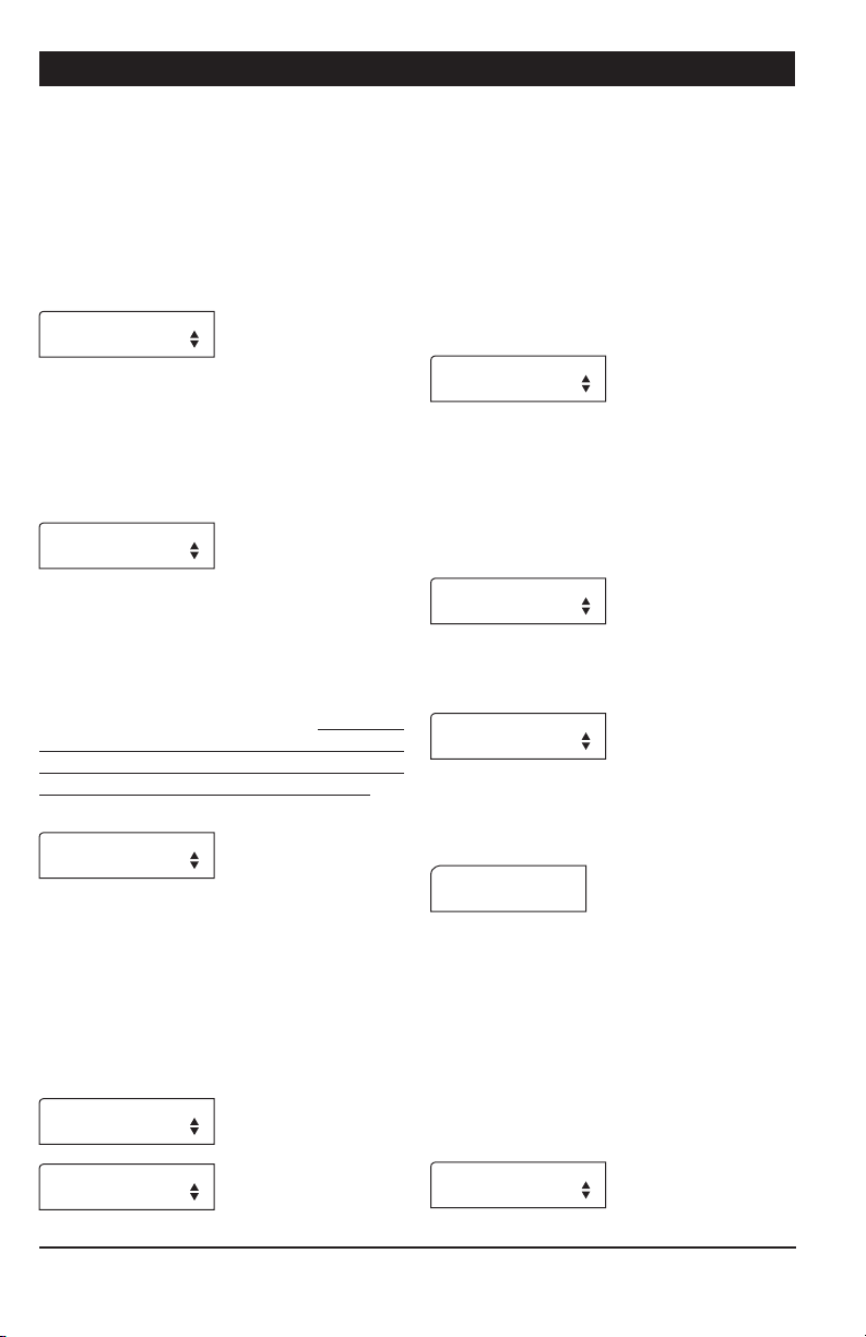
5.6. Installation Setup
The following section describes how to
customize the controller for your particular
application. Normally, this setup needs to be
done only once.
Enter Password — Use the menu select buttons to select the INSTALLATION main menu.
A password may be required to access this
menu. By default, the password is set to
6-1- 0. * This parameter is available if the “Use
Password” setting is set to “Yes”.
Enter password
06 01 00
• The following parameters are presented
below in the order they appear on the display.
To modify a parameter, press MODIF Y then
use the arrow keys to change it. When you are
finished adjusting a parameter, press MODIF Y
once again to validate the new value and
return to the display mode. Press the downarrow key to move to the next parameter.
# of Slaves — Enter the number of additional
Chain Disk Systems in use. Up to 7 Slave
Chain Disk Systems (APCD-500-S) can be
controlled.
# of Slaves
2
Chain Disk System setup — If Slave Chain
Disk Systems are used, select the proper
Chain Disk System setup: select Cascade
if the Chain Disk Systems are connected
together; select Independent if they are
separated from one another. *This parameter
is available if at least 1 slave Chain Disk is enabled
above. Please refer to sections 4.2.1 & 4.2.2 for
further information on these 2 setups.
Chain Disk Sys.
Setup Indep
32
Cascade Chain Disk SystemsIndependent Chain Disk Systems
APCD-500, rev10
Page 33
APCD-500
Common Auger — If independent Slave Chain
Disk Systems are enabled above, specify if
all Chain Disk Systems have their own bin
auger or if they share a common auger. *This
parameter is available if at least 1 independent slave
Chain Disk System is enabled above.
Use Common auger
Yes
Independent
Bin Augers
Common
Bin Auger
Proxy Switch — Select “Ye s” if proximity
sensors are used to detect the presence of
feed in the system.
Use Proxy
Switch? Yes
Proxy Switch Status — Choose the normal
contact status of all proximity sensors in use:
Normally Opened (NO) or Normally Closed
(NC). *This parameter is available if proximity
sensors are enabled.
Proxy Switch
Normally Open
Feed Sensor Bypass — When a feed cycle
starts, some feed leftovers from the previous
cycle are likely to remain. The “Feed Sensor
Bypass Delay” allows ignoring the presence
of these leftovers at the beginning of a feed
cycle. Set this delay separately for each
Chain Disk System in use: Mstr = Master
Chain Disk System, S1,= Slave 1, S2,=
Slave 2, etc. It ranges from 0 to 30 minutes.
* This parameter is available if a proximity sensor
is enabled above and if the system does not use the
common bin auger.
Feed Sensor Mstr
Bypass 0:30m:s
Continuous Feeding / Timed Feeding — Select “Ye s” to use the continuous feeding
mode; select “No” to use timed feed distribution (see sec. 4.3). *The controller automatically
enables the proximity sensor when the continuous
feeding mode is enabled.
Continuous
Feeding? No
Proxy Switch in Drop Tube ? — This parameter tells where the proximity sensor is located
when using the continuous feed distribution
mode. Select “ Yes” if it is mounted in the
last drop tube to be filled in each Chain Disk
System or select “No” if it is located on the
Chain Disk System line after the last drop
and before the fill hopper. * This parameter
is available if the “Continuous feeding” and “Use
Proxy” options are enabled.
Prox Switch in
drop tube? No
Continuous Feeding Delay — This delay is exclusively used in the continuous feeding mode.
Depending on the location of the proximity
sensor, this delay takes a different meaning
(see below). * This parameter is available if the
continuous feeding mode is enabled above.
1. If the proximity sensor is mounted in the
last drop tube to be filled in each Chain Disk
System, the “Continuous Feeding Delay” tells
when to start a feed cycle from the moment
the drop tube is empty (no feed is detected
in the last drop).
2. If the proximity sensor is mounted on the
Chain Disk System line after the last drop and
before the fill hopper, the “Continuous Feeding
De la y” is an estimation of time it will take for
the animals to eat the feed.
The main difference between both
possibilities is that in the first case,
the system is considered as being
empty when the proximity sensor
stops detecting feed; in the second
APCD-500, rev10
33
Page 34
APCD-500
case, it is considered empty after a
user-defined delay (after Continuous
Feeding Delay).
Set the continuous delay to the desired value.
(Please refer to section 4.3.2 for further
information about the continuous distribution mode).
Cont. Feeding
Delay 0:30
Feed Dump : Actuators / Air valves — Select “A ct ua” to enable feed dumps that are
controlled by an actuator; select “Valve” to
enable feed dumps that are controlled by an
air valve; select “None” to disable feed dumps.
* This parameter is available if feed distribution is
based on a timer (if the continuous feeding mode is
disabled above).
Feed dump use
Actua
Clean Drops — This function allows cleaning
the drops immediately following the dump
cycle. The controller uses the “Actuator Open
Ti me” parameter to open and close the drops
3 times in a row in order to evacuate feed
leftovers from the system. The last close will
last twice as long as the open time.
Clean Drops ?
Yes
Chain Disk Motor Recommended Settings
Actuator Open Time — This is the amount
time required for the actuator to open the
dumps. It ranges from 0 to 120 minutes.
* This parameter is available if the actuator is
enabled above.
Actuator Open
Time 3:00m:s
Actuator / Air Valve Delay — This is the
amount of time the dumps remain opened.
It ranges from 0 to 60 minutes.
Actuator/A.Valve
Delay 3:00m:s
Use Act. Security Switch — Select “Yes” if
the actuator has a security switch. * This pa-
rameter is available if the actuator is enabled above.
Use Act.Security
switch? No
Maximum Current of the Master Chain Disk
System — Select the maximum allowable
current that can be consumed by each Chain
Disk System. This parameter ranges from 1
to 10 Amp. (Mstr = Master Chain Disk System, S1,= Slave 1, S2,= Slave 2, etc.) *See
recommended settings on Table 1.
Max Current Mstr
6.0Amp
Max Current
Type
Single phase, 60 Hz 208 - 230 1 1.0 6.0 9.0
Single phase, 50 Hz 190 - 230 1 1.0 6.0 9.0
Three Phase, 60Hz
Three Phase, 50Hz
Voltage
208 - 230 2 1.5 8.0 9.0
460 3 1.0 6.0 7.0
190 2 1.5 9.0 10.0
203 2 1.5 8.0 10.0
380 3 1.0 7.0 9.0
Recommended
number of loops
through current
sensor
Window size
New blue
gearbox
(1.5HP or
2HP
motors)
Table 1: Recommended Settings as a Function of Gearbox Type
34
APCD-500, rev10
Old grey
gearbox
(2HP motors
only)
Critical
Amp
2 amps over
Max Current
setting
Page 35
APCD-500
Window Size — This parameter is used to
restart a drive unit that was stopped due to an
over current condition. The drive unit restarts
when its amperage draw becomes lower than
its respective “Max Current Consumption - Win-
do w S iz e”. The window size is common to all
drive units and ranges from 0.5 to 3.0 Amp.
*See recommended settings on Table 1.
Window Size
1.0Amp
Over Current Delay — An alarm sets off when
the amperage draw of a drive unit exceeds
its respective maximum current limit for this
amount of time. The over current delay is
common to all drive units and ranges from
30 seconds to 15 minutes.
Over Current
Delay 4:00m:s
Critical Amperage Draw & Delay — Specify
the critical amperage level and the maximum
amount of time this level can be maintained
before the system stops. The Critical amperage draw ranges from 6 to 15Amp and the
delay ranges from 0 to 2 minutes. To prevent
damage to the motor and to the electronic
components of the controller, we recommend
limiting the delay to 4 seconds or less.*See
recommended settings on Table 1.
Cri. Amp. 8.0Amp
Delay 0:10m:s
Max Run Time — This is the maximum allowable running time of a Chain Disk System. The
controller sounds an alarm when the continuous run time of a Chain Disk System exceeds
the Max Run Time limit of this Chain Disk System. Set this parameter separately for each
Chain Disk System in use (Mstr = Master
Chain Disk System, S1,= Slave 1, S2,=
Slave 2, etc.). It ranges from 00:01 hh:mm
to 18:00 hh:mm.
Max Run Time Mstr
2:15h:m
# of Feeding Cycles — Activate the proper
number of daily feed cycles. Up to 25 cycles
can be activated. * The controller automati-
cally restrain the number of feed cycles so that no
cycle overlaps another. Refer to sec. 5.4 to set the
feed cycles.
# of Feeding
Cycles 1
Time Mode — Select the desired time display
format: 12h or 24h mode.
Time Mode 12h
Contrast — Set the contrast of the LCD
screen to the desired value (from 10 to
100%).
Contrast: 80
Auger Delay — When a feed cycle starts, the
activation of the bin auger is postponed until
the end of this delay. This allows emptying
the Chain Disk Systems before bringing new
feed into the system. If all Chain Disk Systems have their own bin augers, set this delay
separately for each Slave Chain Disk System.
The auger delay ranges from 0 to 60 minutes.
Auger Delay Mstr
0:15m:s
Auger Delay S1
0:15m:s
Shut Down Delay — When a proximity sensor detects feed at the end of a Chain Disk
System, the controller stops the feed entry
(bin auger) and launches the “Shutdown Delay”
before stopping the drive unit. This delay
ranges from 0 to 10 minutes. Set this parameter separately for each Chain Disk System in
use (Mstr = Master Chain Disk System, S1,=
Slave 1, S2,= Slave 2, etc.) * This parameter
is available if proximity sensors are enabled above.
Shut down delay
0:10m:s
APCD-500, rev10
35
Page 36
APCD-500
Feed Purge Time Delay — The “Feed Purge
De la y” is the amount of time required for feed
lines to get empty when a common auger is
used. Note that the “Purge Delay” must be
higher than “A u g e r D e l a y ”. Set this parameter to the desired value. * This parameter is
available if many Chain Disk Systems are sharing
a common bin auger.
Feed Purge Time
Delay 1:00m:s
Use Password — Select “Yes” to enable a
password; this password is used to restrain
the access to the Installation and Feed Cycle
menus.
Use password?
Yes
Change password? — Select “Yes” if you
wish to modify the controller’s password then
press the down-arrow key. *This parameter is
available if the password option is enabled above.
Change password?
Yes
1. Press MODIFY. The first two digits of
the password flash on the display.
EnterNewPassword
** ** **
2. The new password must be entered,
one number at a time. Use the arrow keys
to enter the first number. Press MODIF Y
to step to the next number. Use the arrow
keys to enter the second number, etc.
Version — This is the current version of your
controller.
APCD-500
Version X.X
36
APCD-500, rev10
Page 37
APCD-500
5.7. Manual & Test Modes
The manual mode allows activating manually
the actuators, air valves and drive units.
5.7.1. Manual Filling of the Chain Disk Systems
It is possible to fill some Chain Disk Systems
without waiting for a feed cycle to start.
When this manual start-up is performed, the
Manual Mode pilot light turns on and the
controllers activates the proper outputs in
order to fill up the required Chain Disk
System(s) (see the different filling methods
in section 4.5.2). The manual filling process
ends when the Chain Disk System is full.
If the user manually adds feed to
a Chain Disk System while a feed
cycle is ongoing, the ongoing cycle
will be bypassed and replaced by the manual
filling process. When the controller returns to
the automatic mode, it will not resume the
previous cycle but will wait for the next Dump
Time (if applicable). A manual dump can also
be performed (see next section). Do not forget
to exit from the manual mode when the manual
filling process is completed.
5.7.2. Manual Start / Stop
You can choose to start filling a Chain Disk
System or to stop it manually (as explained
in previous section).
1. Use the menu select buttons to select the
MANUAL MODE menu.* A password may be
required to access this menu (see sec. 5.6).
2. The manual mode status is displayed on
screen.
Feed cycles
Mode Auto
3. Press MODIFY then use the arrow keys
to select the desired status: select “Start”
to enable the manual mode; select “Stop” to
stop the Chain Disk system; select “A u t o” to
return to the automatic control mode.
1. Use the menu select buttons to select the
MANUAL MODE menu. *A password may be
required to access this menu (see sec. 5.6).
2. Before enabling the manual filling, select
which Chain Disk System must be filled:
press the down-arrow key to select the
“Manual Start” parameter.
Manual Start
Mastr
3. Press MODIFY then use the arrow keys to
select the Chain Disk System that needs to
be filled manually (Master Chain Disk System,
All Chain Disk Systems or slave 1-7 Chain
Disk Systems). Press MODIF Y once again to
validate. When the desired Chain Disk System is selected, activate the manual mode as
shown in section 5.7.2.
APCD-500, rev10
37
Page 38
APCD-500
5.7.3. Bypassing a Chain Disk System
If required, the controller can bypass a Chain
Disk System (slave or Master Chain Disk
System).
If a bypassed slave Chain Disk
System shares a common bin auger
with other Chain Disk Systems, the
bypassed Chain Disk System will
still run during the “Purge Time” at
the beginning of each cycle.
1. Use the menu select buttons to select the
MANUAL MODE menu. *A password may be
required to access this menu (see sec. 5.6).
2. Press the down-arrow key to select the
status menu of the desired Chain Disk System. * This parameter is available if at least 1 slave
Chain Disk System is enabled.
APCD-500 Master
Status Auto/Bypas
APCD-500-S #1
Status Auto/Bypas
3. Press MODIFY then use the arrow keys
to select the desired status (Auto /Bypass).
Press MODIF Y again to validate.
5.7.4. Manual Dump
The actuator/air valve can only be activated
manually when no drive unit is running. The
Manual Mode pilot light flashes while an actuator or air valve is controlled manually.
1. Use the menu select buttons to select the
MANUAL MODE menu.
Press the down-arrow key to select the
manual mode status of the actuator. * This
parameter is available if the actuator is enabled
(see sec. 5.6).
Actuator
Mode: Auto
2. Press MODIFY then use the arrow keys to
select the desired status (Auto /Open /Stop/
Close). Press MODIFY again to validate. * The
answer is validated after 8 seconds.
3. Press the down-arrow key once. The
manual mode status of the air valve is displayed. * This parameter is available if the air valve
is enabled (see sec.5.6).
4. Press MODIFY then use the arrow keys to
select the proper status (Auto/Open/ Close).
Press MODIF Y again to validate.* The answer
is validated after 8 seconds.
38
APCD-500, rev10
Page 39

APCD-500
5.7.5. Toggle Switch
A toggle switch can be connected to the main
board. This switch allows stopping the drive
unit of the master Chain Disk System and
stopping bin augers manually. If the toggle
switch is turned off for 30 consecutive seconds, the Chain Disk is Not Running alarm will
be activated. Refer to the wiring diagram
enclosed with this manual to connect the
toggle switch.
The toggle switch does not cut the
power lines to the chain disk control-
ler. Shut off the circuit breaker for
servicing and maintenance.
5.7.6. Test Mode
The test mode allows simulating the amperage draw of all drive units in order to verify
the controller’s performances.
1. Use the menu select buttons to select the
MANUAL MODE menu.
2. Press the down-arrow key to select the
amperage draw display of the drive unit of
the master Chain Disk System or of a slave
Chain Disk System.
3. Press the down-arrow key to select the
amperage draw of the selected drive unit.
4. Press MODIFY then use the arrow keys to
set the simulated current consumption. Press
MODIFY to validate. * The answer is validated
after 8 seconds.
Do not forget to exit from the test
mode when tests are completed.
APCD-500, rev10
39
Page 40
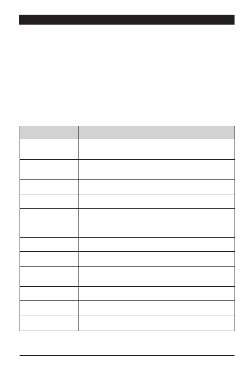
APCD-500
5.8. Alarms
The following table shows the possible alarms
conditions. When an alarm occurs, the whole
Chain Disk system stops operating until the
alarm is acknowledged.
Trouble Light:
It is possible to connect a trouble light to the
main controller. This light turns on whenever
an alarm occurs. Refer to the wiring diagram
enclosed with this manual to connect this
light.
Alarm
Messages
Actuator is
not closed
Actuator is
not opened
APCD-500-S #x
comm alarm
Chain disk is
not running
Current
overload
Current overload
APCD-500-S #x
Max run time The running time of the master Chain Disk drive unit exceeded
Max run time
APCD-500-S #x
Critical Amp The amperage draw of the master Chain Disk System exceeded
Critical Amp
APCD-500-S #X
Chain disk safety
switch
Chain disk safety
swi tch APCD-500-S #X
Meaning
The actuator security switch has not been reached after the Closing Time (this type of alarm can only occur if the actuator security
switch is enabled).
The actuator security switch is still detected after the Opening
Time (this type of alarm can only occur if the actuator security
switch is enabled in the installation).
Communication is disrupted between the main controller and an
APCD-500-S slave module ID# x.
The amperage draw of the master Chain Disk System is lower
than 0.5 A.
The amperage draw of the master Chain Disk System exceeded
its Maximum Current Consumption limit for the Over Current Delay.
The amperage draw of slave Chain Disk ID System # X exceeded
the Maximum Current Consumption limit for the Over Current Delay.
the Max.Run Time parameter value.
The running time of slave Chain Disk System ID #X exceeded
the Max.Run Time parameter value.
its Critical Amp. limit for the Critical Delay. All Chain Disk Systems
stop running when this type of alarm is on.
The amperage draw of slave Chain Disk System ID # X exceeded
the Critical Amp. limit for the Critical Delay.
The safety switch of the master Chain Disk System has been
reached.
The safety switch of slave Chain Disk System ID #X has been
reached.
5.8.1. Acknowledging an alarm
1. Use the menu select buttons to select the
STAT US menu. The current alarm acknowledgment menu is displayed.
2. Press MODIFY. The acknowledgment status flashes on the display.
3. Press the up-arrow key to acknowledge
the alarm then press MODIFY to validate.
The alarm is now acknowledged.
40
APCD-500, rev10
Page 41

APCD-500
6. TECHNICAL SPECIFICATIONS
Typ e .................................. APCD-500
Main supply fuse F1 ............. F1A, 250V, fast-blow
Main supply/frequency ........230V+10% -20%, 12A, 50/60Hz
Housing .............................Plastic casing
Operating temperature ........0 to 40°C
Storage temperature ........... -15 to 50°C
Ambient relative humidity ...Max 95% (non-condensing)
Alarm ................................ 10mA to 2A, 24 Vac or Vdc max
Auger motor ......................230Vac/1HP max, 115Vac/1/2HP max
Internal contactor ...............230Vac / 2HP max
Nema Code Let ter: ......... A to L max
Full-load amps (FL A): ...... 13A max
Locked rotor amps (LRA): 17 0A ma x
Running a motor with higher ratings could result in potential
controller damages and/or fire. If the Nema Code Letter
is not available, exclusively use the LRA ratings!
Actuator/Air valve ................ 230Vac ma x, 5A max
Trouble light .......................50 0W max, 115VAC
Installation category ...........Category II : Overvoltage category
Pollution degree .................2
Altitude ............................. Up to 2000m
The room temperature where the controller is located
must always remain between 32 and 104°F (0 and
40°C). For indoor use only!
APCD-500, rev10
41
Page 42

APCD-500
7. TRANSFER MENU
7.1. Communication Speed
1. Simultaneously press and hold the MENU
SELECT up- and down-arrow keys for 5 seconds to display the transfer menu.
1. MemoryCard -> Control
2. Control -> MemoryCard
3. Update Firmware
4. Save EventBuffer
5. Comm speed
6. Contrast
2. Choose 5. Comm Speed and press MODIF Y.
3. Set the communication speed to the right
value: select the high speed mode if the controller uses the A-BOX communication system
or select the low speed if it uses AGNET.
4. Press MODIFY to validate the new value.
5. Simultaneously press and hold the MENU
SELECT up- and down-arrow keys for 5 seconds to exit from the transfer menu.
7.2. Screen Contrast
7.3. Update/Backup with a USB drive
The USB drive allows upgrading the firmware
or software of your controller. It can also be
used to make a backup of your controller
settings or to copy these settings on another
controller of the same type.
Turn off power each time you open
the controller’s enclosure. This prevents accidental exposure to areas
of high voltage.
1. Turn off power to the controller.
2. Lift the latch to open the front door of the
controller.
3. Insert the USB drive in the connector
behind the front door.
USB dr ive
1. Simultaneously press and hold the MENU
SELECT up- and down-arrow keys for 5 seconds to display the transfer menu.
2. Choose 6. Contrast and press MODIF Y.
3. Set the contrast of the LCD screen to the
desired value.*The contra st can also be adjusted in the
setup menu on some controllers.
4. Press MODIFY to validate the new value.
5. Simultaneously press and hold the MENU
SELECT up- and down-arrow keys for 5 seconds to exit from the transfer menu.
42
APCD-500, rev10
Figure 1 : USB Connector
4. Close the front cover and reapply power
to the controller.
5. Simultaneously press and hold the MENU
SELECT up- and down-arrow keys for 5 seconds to display the transfer menu.
1. MemoryCard -> Control
2. Control -> MemoryCard
3. Update Firmware
4. Save EventBuffer
5. Comm speed
6. Contrast
Page 43

APCD-500
1. MemoryCard -> Control
Choose 1. MemoryCard -> Control and press
MODIFY to load a new configuration file into
your controller. This transfer will update your
controller’s software and parameter settings.
1
Select file & press
2
FI L E~1.DM P
3
FI LE ~2.D M P
4
FI L E~3.D MP
5
When selecting this option, a list of all configuration files located on the card is displayed
(*.DMP files). Select the desired file and then
press the ADJUSTMENT up- and down-arrow
keys for 5 seconds to start the transfer.
Note that the controller can only read
the files that are located at the root
of the USB drive. It cannot access
any sub-directory!
2. Control -> MemoryCard
Choose 2. Control -> MemoryCard and press
MODIFY to save your controller settings on
the USB drive. The saving process will start
as soon as you enter this menu.
1
Select file & press
2
FI L E~1.DM P
3
FI LE ~2.D M P
4
FI L E~3.D MP
5
3. Update Firmware
Choose 3. Update Firmware and press MODI-
FY to download a new firmware file into your
controller. This process will not affect your
parameter settings.
1
Select file & press
2
FI L E~1.P K G
3
FI LE ~2.P KG
4
FI L E~3.PK G
5
When selecting this option, a list of all
firmware files located on the USB drive is
displayed (*.PKG files). Select the desired file
and then press ADJUSTMENT up - and downarrow keys for 5 seconds to start the transfer.
Note that the controller can only read
the files that are located at the root
of the USB drive. It cannot access
any sub-directory!
4. Save Event Buffer
Choose 4. Save Event B uffer and press MOD-
IFY to save the event buffer of the controller
on your USB card (event.txt).
Simultaneously press and hold
the MENU SELECT up- and downarrow keys for 5 seconds to exit
from the transfer menu.
The controller will create a new CONTROLLER~1.DMP file at the root of the USB drive.
If this file name already exists, it will be saved
under a different name (“CONTROLLER~2.
DMP” for instance). This way, the controller
will never erase a file on the card.
Remove the USB drive from the
connector when the transfer
is over!
APCD-500, rev10
43
Page 44

APCD-500
ANNEX 1: CORE CARD
Removing a Core Card:
Before proceeding, switch power off
at service panel and lock the switch
disconnecting means to prevent
power from being switched accidentally. When the service disconnecting
means cannot be locked, securely
fasten a prominent warning device,
such as a tag, to the service panel.
1. Use your thumbs to move away the two
metal arms that are retaining the card. While
doing so, lift the card upwards with your
index fingers.
Inserting a Core Card:
Before proceeding, switch power off
at service panel and lock the switch
disconnecting means to prevent
power from being switched accidentally. When the service disconnecting
means cannot be locked, securely
fasten a prominent warning device,
such as a tag, to the service panel.
1. Give the card a 45-degree angle before
inserting it in the connector.
2. Once it is inserted, the card wil stand at
the 45-degree position.
2. Pull the card out of its connector.
44
APCD-500, rev10
3. Press on the card and make it clip to the
main board.
Page 45

APCD-500
INDEX
A
Actuator / Air valve
Activation & settings 34
Actuator status LED 6
Current actuator status 29
Dump
Manual feed dump 38–39
Principle of operation 28
Settings 30
Principle of operation 28
Security switch 34
Adjusting a parameter 7
Air valve see Actuator/Air Valve
Alarms
Alarm conditions 40
Status LED 6
Amperage draw see Chain Disk
Auger see Bin auger
B
Backup 42
Bin auger
Auger status LED 6
Principle of operation 11
Settings 33, 35
Buttons 6
C
Card (Core) 44
Card (Memory) 42
Chain Disk System
Amperage draw
Current status 29
Overload protection 11
Overload protection settings 34
Test mode 39
Chain disk status LED 6
Filling Process see Feeder setup
Manual lling 37
Run time
History 29
Max run time 35
Run time settings 32
Safety switch
Status LED 6
Setup
Cascade setup
Activation 32
Feeders’ lling process 11, 13–15, 15, 37
Setup view 8
Independent feeders with 1 auger
Activation 32
Feeders’ lling process 11, 18–20, 37
Setup view 9
Independent feeders with ind. augers
Activation 32
Feeders’ lling process 11, 23–25, 37
Setup view 9
Communication speed 42
Connections 7
Contrast 42
Controller
Backup 42
Controller’s description 8
Current status 29
Location of the controls 6
Mounting instructions 7
Status LEDs 6
Update 42
Version 36
Core card (replacement) 44
Current consumption see Chain Disk
D
Date 30
Display 6
Drive units see Chain Disk
Dumps see Actuator/ Air valve
E
Electrical specications 41
F
Feed cycles
Activation 35
Feed cycle status 29
Principle of operation 28
Programming feed cycles 30
Warning 30, 37
APCD-500, rev10
45
Page 46

APCD-500
Feed distribution
Continuous mode
Activation & settings 33
Feed delivery process 28
Feeders’ lling process see Feeder setup
Principle of operation 10
Settings 33
Timer mode
Activation 33
Feed delivery process 28
Feeders’ lling process see Feeder setup
Principle of operation 10
Programming feed cycles 28, 30
Feeder motor see Chain Disk
Flex auger see Bin auger
H
History 29
I
Installation setup 32–36
K
Keys 6
L
LCD display
Contrast 42
Location 6
LEDs (status) 6
Limit switch see Actuator - Security switch
M
Manual mode
Activation 37
Dumping feed manually 38
Filling the feeders manually 37
Status 29
Status LED 6
Memory card 42
Menu selection 6
Motor see Chain Disk
Mounting instructions 7
P
Parameter adjustment 7
Password
Activation 36
Change the password 36
Enter a password 32
Pilot lights see also LEDs
Trouble light 40
Proximity sensor
Activation & settings 33
Feed switch status LED 6
Location
Settings 33
Visual representation 10
R
Run time
History 29
Max run time
Settings 35
Status LED 6
Run time settings 28, 32
S
Safety switch for Chain Disk
see Chain Disk safety switch
Screen
see LCD Display
Security switch for actuators
see Actuator - Security switch
Slave Chain Disk 8
Activation 32
Speed (communication) 42
Status
Current controller status 29
Status LEDs 6
T
Technical specications 41
Test mode 39
Status 29
46
APCD-500, rev10
Page 47

APCD-500
Time
Adjusting improper system time 30
Time and date 30
Time format 35
Toggle switch 39
Transfer menu 42
Trouble light 40
U
Update 42
USB drive 42
V
Valve see Actuator /Electric V.
Version 36
W
Warnings
Check feed cycles 30, 37
APCD-500, rev10
47
 Loading...