

GSi 40 Series Construction Manual

36 Ft. Diameter Bins (14 Rings
and Taller)
Models:
40-SERIES 4.00'' CORRUGATION BINS
6000 LB. PEAK LOAD ROOF WITH 40SERIES STIFFENERS
Construction Manual
PNEG-4336
Version 4.0
Date: 10-22-18
PNEG-4336

All information, illustrations, photos, and specifications in this manual are based on the latest
information available at the time of publication. The right is reserved to make changes at any
time without notice.
2
PNEG-4336 36 Ft. Diameter 40-Series Bins

Contents
Chapter 1 Safety Precautions ....................................................................................................................5
Safety Guidelines for Bins............................................................................................................6
Cautionary Symbol Definitions......................................................................................................7
Safety Cautions...........................................................................................................................8
Safety Decals ........................................................................................................................... 13
Safety Sign-off Sheet................................................................................................................. 15
Chapter 2 General Overview ....................................................................................................................17
General Information...................................................................................................................17
Tools Required for Construction.................................................................................................. 17
Guidelines for Proper Storage of Grain Bin Materials Prior to Construction.....................................18
Overview for a Typical Bin Installation ......................................................................................... 18
Guidelines for Construction Procedures and Lifting Jack Usage .................................................... 19
Instructions for Stirring Devices ..................................................................................................20
Guidelines for Placement of the Decal Sidewall Sheet..................................................................21
Anchor Bolt Detail ..................................................................................................................... 22
Anchor Bolt Charts ....................................................................................................................23
Chapter 3 Hardware requirements ........................................................................................................... 25
Bolt and Nut Pairings ................................................................................................................. 25
Hardware for Sidewall Sheets on 4 in. Corrugation Bins ............................................................... 26
Bolt Torque Specifications.......................................................................................................... 26
Identifying Bolt Grades ..............................................................................................................27
Bolt Identification....................................................................................................................... 28
Bolt S-10260 .............................................................................................................................28
Bolt S-7483...............................................................................................................................28
Bolt S-7485...............................................................................................................................28
Bolt S-7487...............................................................................................................................29
Bolt S-7488...............................................................................................................................29
Bolt S-10261 .............................................................................................................................29
Color Chart for Bin Hardware Bucket Lids ................................................................................... 30
Chapter 4 Assembling Sidewall Sheets ................................................................................................... 31
Guidelines for Constructing Sidewall Sheets ............................................................................... 31
Color Codes for Sidewall Gauge Identification ............................................................................. 31
Gauge Sheet ............................................................................................................................ 32
Orientation Detail for Top Sidewall Sheets ................................................................................... 33
Caulking and Bolting Detail for Standard Sidewall Sheets............................................................. 34
Chapter 5 Base Angle Installation ........................................................................................................... 37
Installing the Base Angle............................................................................................................ 37
Installing the Base Angle Shims ................................................................................................. 39
Anchor Bolt Washer Installation ..................................................................................................40
Chapter 6 Stiffeners................................................................................................................................. 41
Stiffener Starting Location..........................................................................................................42
Stiffener Splice Location ............................................................................................................ 43
Stiffener Part Number Description ..............................................................................................44
Color Codes for Stiffener Gauge Identification ............................................................................. 44
Standard Stiffeners....................................................................................................................45
Top Stiffeners............................................................................................................................46
Stiffeners Splice ........................................................................................................................ 47
Base Stiffeners ......................................................................................................................... 48
Base Boots ............................................................................................................................... 49
One-Ring Top Stiffener (16 Ga) to a One-Ring Stiffener (15–16 Ga) ..............................................50
One-Ring Top Stiffener (16 Ga) to a Two-Ring Stiffener (15–16 Ga) ..............................................50
One-Ring Top Stiffener (16 Ga) to a Two-Ring Stiffener (8–14 Ga) ................................................51
One-Ring Stiffener (15–16 Ga) to a Two-Ring Stiffener (15–16 Ga) ...............................................51
PNEG-4336 36 Ft. Diameter 40-Series Bins
3

One-Ring Stiffener (15–16 Ga) to a Two-Ring Stiffener (8–14 Ga) ................................................. 52
Two-Ring Stiffener (15-16 Ga) to a Two-Ring Stiffener (8–14 Ga)..................................................52
Two-Ring Stiffener (15-16 Ga) to a Two-Ring Stiffener (15–16 Ga)................................................53
Two-Ring Stiffener (8–14 Ga) to a Two-Ring Stiffener (8–14 Ga) Connection ................................. 53
Two-Ring Stiffener (8–14 Ga) to a Two-Ring Stiffener (2–6 Ga) Connection ................................... 54
Two-Ring Stiffener (8–14 Ga) to a Base Stiffener (8 Ga) ...............................................................54
Two-Ring Stiffener (8–14 Ga) to a Base Stiffener (10–16 Ga) Connection......................................55
Two-Ring Stiffener (2–6 Ga) to a Base Stiffener (2–6 Ga) .............................................................55
Two-Ring Stiffener (15–16 Ga) to a Base Stiffener (10–16 Ga)......................................................56
Two-Ring Stiffener (2–6 Ga) to a Laminated Stiffener (2 Ga) with an Insert (10–12 Ga)................... 56
Laminated Stiffeners (2 Ga) with Inserts (10–12 Ga) .................................................................... 57
Laminated Stiffener (2 Ga) with an Insert (10–12 Ga) to a Laminated Base Stiffener (2 Ga) with
a Base Insert (2–12 Ga)................................................................................................. 57
Base Stiffener (10–16 Ga) to a Base Boot ...................................................................................58
Base Stiffener (2+12 Ga – 8 Ga) to a Base Boot ..........................................................................58
Laminated Base Stiffener (2 Ga) with Insert (2+12 to 2+10 Ga) to a Base Boot .............................. 59
Standard Stiffener to a 12–Bolt Pattern Laminated Stiffener with Insert..........................................59
12–Bolt Pattern Laminated Stiffeners with Insert ..........................................................................60
12–Bolt Pattern Laminated Stiffener to Laminated Base Stiffener with Inserts to a Base
Boot ............................................................................................................................. 61
12–Bolt Pattern Laminated Stiffener to Laminated Base Stiffener with an Inserts to a Base
Boot ............................................................................................................................. 62
Chapter 7 Door Assembly........................................................................................................................63
Door Placement ........................................................................................................................64
Two Ring Door Assembly........................................................................................................... 65
Options for Two Ring Door - Bin Step .......................................................................................... 78
Chapter 8 Roof Assembly ........................................................................................................................ 79
Roof Assembly Instructions........................................................................................................ 79
Assembling Center Collar .......................................................................................................... 80
Assembling the Intermediate Center Collar..................................................................................81
Roof Flashing ........................................................................................................................... 82
Roof Panel Instructions..............................................................................................................83
Installing the Manway Cover ......................................................................................................86
Roof Ring Locations ..................................................................................................................88
Installing a Roof Ring.................................................................................................................89
Chapter 9 Accessories ............................................................................................................................ 91
Ladder Section Assembly .......................................................................................................... 92
Inside Ladder Placement ........................................................................................................... 93
Installing the Inside Ladder Bottom Bracket .................................................................................96
Guidelines for Installing a Sidedraw System ................................................................................97
Locating the Chutes................................................................................................................... 99
Locating Discharge Opening .................................................................................................... 100
Sidewall Overlap ..................................................................................................................... 101
Caulking ................................................................................................................................. 102
Installing the Wind Rings.......................................................................................................... 103
Temperature Cable Support Package Instructions for Eave Heights of 40 ft. - 5 in. (12.32 m) or
Less (Optional) ........................................................................................................... 105
Temperature Cable Support Package Instructions for Eave Heights Greater than 40 ft. - 5 in.
(12.32 m) (Optional) .................................................................................................... 107
Assembling Weather Cover for Roller Valve .............................................................................. 110
Transition Assembly ................................................................................................................ 111
Seal Kit (Optional) ................................................................................................................... 113
GSI Group, LLC Limited Warranty ......................................................................................... 115
4
PNEG-4336 36 Ft. Diameter 40-Series Bins

1 Safety Precautions
Topics Covered in this Chapter
▪ Safety Guidelines for Bins
▪ Cautionary Symbol Definitions
▪ Safety Cautions
▪ Safety Decals
▪ Safety Sign-off Sheet
PNEG-4336 36 Ft. Diameter 40-Series Bins
5

Chapter 1: Safety Precautions
Safety Guidelines for Bins
Safety guidelines must be followed at all times. This manual is written to help you understand safe operating procedures and problems that can be encountered by the operator and other personnel when using
this equipment. Save these safety guidelines for future reference.
As owner or operator, you are responsible for understanding the requirements, hazards, and precautions
that exist and to inform others as required. Unqualified persons must stay out of the work area at all
times.
Alterations must not be made to the equipment. Alterations can produce dangerous situations resulting in
SERIOUS INJURY or DEATH.
This equipment must be installed in accordance with the current installation codes and applicable regulations, which should be carefully followed in all cases. Authorities having jurisdiction must be consulted
before installations are made.
When necessary, you must consider the installation location relative to electrical, fuel and water utilities.
Personnel operating or working around equipment must read this manual. This manual must be delivered
with equipment to its owner. Failure to read this manual and its safety instructions is a misuse of the
equipment.
This product is intended for the use of grain storage only. Any other use is a misuse of the product.
Sidewall bundles or sheets must be stored in a safe manner. The safest method of storing sidewall bundles is by laying them horizontally with the arch of the sheet upward, like a dome. Sidewall sheets stored
on edge must be secured so that they cannot fall over and cause injury. Use care when handling and
moving sidewall bundles.
This product has sharp edges, which may cause serious injury. To avoid injury,
handle sharp edges with caution and always use proper protective clothing and
CAUTION
equipment.
ST-0035
6
PNEG-4336 36 Ft. Diameter 40-Series Bins

Chapter 1: Safety Precautions
Cautionary Symbol Definitions
Cautionary symbols appear in this manual and on product decals. The symbols alert the user of potential
safety hazards, prohibited activities and mandatory actions. To help you recognize this information, we
use the symbols that are defined below.
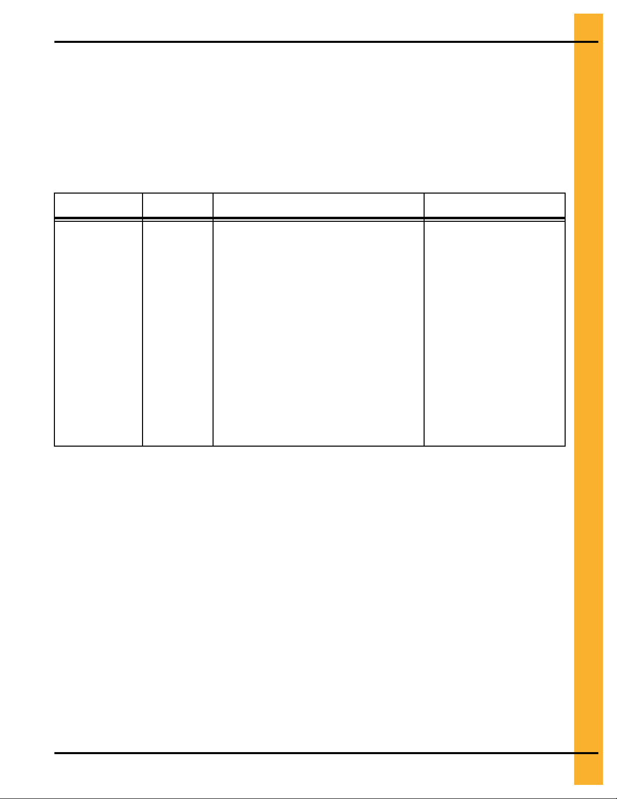
Table 1-1 Description of the different cautionary symbols
Symbol Description
This symbol indicates an imminently hazardous situation which, if
not avoided, will result in serious injury or death.
This symbol indicates a potentially hazardous situation which, if not
avoided, can result in serious injury or death.
This symbol indicates a potentially hazardous situation which, if not
avoided, can result in minor or moderate injury.
This symbol is used to address practices not related to personal
injury.
This symbol indicates a general hazard.
This symbol indicates a prohibited activity.
This symbol indicates a mandatory action.
ST-0005–2
PNEG-4336 36 Ft. Diameter 40-Series Bins
7

Chapter 1: Safety Precautions
Safety Cautions
Use Personal Protective Equipment
• Use appropriate personal protective equipment:
Eye
Protection
Hearing
Protection
Hand
Protection
• Wear clothing appropriate to the job.
• Remove all jewelry.
• Tie long hair up and back.
Follow Safety Instructions
Respiratory
Protection
Head
Protection
Foot
Protection
Fall
Protection
ST-0004–1
• Carefully read all safety messages in this manual and safety
signs on your machine. Keep signs in good condition.
Replace missing or damaged safety signs. Be sure new
equipment components and repair parts include the current
safety signs. Replacement safety signs are available from
the manufacturer.
• Learn how to operate the machine and how to use controls
properly. Do not let anyone operate without instruction.
• If you do not understand any part of this manual or need
assistance, contact your dealer.
ST-0002–1
8
PNEG-4336 36 Ft. Diameter 40-Series Bins

Maintain Equipment and Work Area
• Understand service procedures before doing work. Keep
area clean and dry.
• Never service equipment while it is operating. Keep hands,
feet, and clothing away from moving parts.
• Keep your equipment in proper working condition. Replace
worn or broken parts immediately.
Do Not Enter Bin
• Rotating flighting will kill or dismember.
• Flowing material will trap and suffocate.
• Crusted material will collapse and suffocate.
— If you must enter the bin:
1. Shut off and lock out all power sources.
Chapter 1: Safety Precautions
ST-0003–1
2. Use a safety harness and safety line.
3. Station another person outside the bin.
4. Avoid the center of the bin.
5. Wear proper breathing equipment or respirator.
ST-0061–1
PNEG-4336 36 Ft. Diameter 40-Series Bins
9

Chapter 1: Safety Precautions
Unload the Bin Correctly
• Use CENTER FLOOR OUTLET ONLY until NO grain
remains above this outlet.
• Side floor outlets to be used ONLY when above condition
is satisfied.
• Lock all side floor outlets to avoid accidental premature
use.
• See manufacturers instructions for proper use of factory
supplied sidedraw (wall) discharge systems.
Prevent Roof Damage Due to Vacuum Pressure
• Roof damage can result from excessive vacuum or internal
pressure from fans or other air moving systems. The manufacturer does not warrant this type of roof damage.
• Adequate ventilation or “makeup air” devices must be provided for all powered air handling systems.
ST-0060–1
• The manufacturer does not recommend the use of downward flow systems (suction).
• Severe roof damage can result from any blockage of air
passages.
• Operating fans during high humidity or cold weather conditions can cause air exhaust or intake ports to freeze.
Sharp Edge Hazard
• This product has sharp edges, which can cause serious
injury.
• To avoid injury, handle sharp edges with caution and always
use proper protective clothing and equipment.
ST-0028–2
10
ST-0036–2
PNEG-4336 36 Ft. Diameter 40-Series Bins

Rotating Auger Hazard
• Keep clear of rotating augers and
moving parts.
• Do not remove or modify guards or
covers.
• Lock-out power source before making
adjustments, cleaning, or maintaining
equipment.
• Failure to follow these precautions will
result in serious injury or death.
Stay Clear of Hoisted Equipment
• Always use proper lifting or hoisting equipment when assembling or disassembling equipment
• Do not walk or stand under hoisted equipment.
Chapter 1: Safety Precautions
ST-0037–1
• Always use sturdy and stable supports when needed for
installation. Not following these safety precautions creates
the risk of falling equipment, which can crush personnel and
cause serious injury or death.
Do Not Overfill the Bin
• Do not overfill bin. Stored grain must be no higher than the
roof eaves at the outer edge.
• Filling the bin above this point creates excessive internal
pressure and can cause swelling and eventual roof failure.
The over filling of a bin can also cause the blockage of roof
vents and eaves, which will lead to a build-up of air pressure causing roof damage.
Install and Operate Equipment Properly
• This product is intended for the use of grain storage only.
Any other use is a misuse of the product.
ST-0047–1
ST-0050–1
PNEG-4336 36 Ft. Diameter 40-Series Bins
ST-0057–1
11

Chapter 1: Safety Precautions
Store Bin Sheets Properly
• Sidewall bundles or sheets must be stored in a safe manner.
The safest method of storing sidewall bundles is by laying
them horizontally with the arch of the sheet upward, like a
dome.
• Sidewall sheets stored on edge must be secured so that they
cannot fall over and cause injury.
• Use care when handling and moving sidewall bundles.
ST-0058–1
12
PNEG-4336 36 Ft. Diameter 40-Series Bins
Chapter 1: Safety Precautions
Safety Decals
The safety decals on your equipment are safety indicators which must be carefully read and understood
by all personnel involved in the installation, operation, service and maintenance of the equipment.
To replace a damaged of missing decal, contact us to receive a free replacement.
GSI Decals
1004 E. Illinois Street
Assumption, IL 62510
Phone: 1–217–226–4421
Location Decal No. Decal Description
Located next to
aeration system.
DC-995
Caution Vacuum Pressure
PNEG-4336 36 Ft. Diameter 40-Series Bins
13

Chapter 1: Safety Precautions
Location Decal No. Decal Description
On bin door
covers
On bin door
covers
DC-GBC-1A
DC-GBC-2A
Danger Keep Clear of
Augers
Warning Unload Instructions
14
PNEG-4336 36 Ft. Diameter 40-Series Bins
Chapter 1: Safety Precautions
Safety Sign-off Sheet
Below is a sign-off sheet that can be used to verify that all personnel have read and understood the safety
instructions. This sign-off sheet is provided for your convenience and personal record keeping.
Date Employee Name
Supervisor Name
PNEG-4336 36 Ft. Diameter 40-Series Bins
ST-0007
15

NOTES
16
PNEG-4336 36 Ft. Diameter 40-Series Bins

2 General Overview
Topics Covered in this Chapter
▪ General Information
▪ Tools Required for Construction
▪ Guidelines for Proper Storage of Grain Bin Materials Prior to Construction
▪ Overview for a Typical Bin Installation
▪ Guidelines for Construction Procedures and Lifting Jack Usage
▪ Instructions for Stirring Devices
▪ Guidelines for Placement of the Decal Sidewall Sheet
▪ Anchor Bolt Detail
▪ Anchor Bolt Charts
General Information
General information, overview and instructions needed before performing work.
Read this manual carefully. This manual will provide instructions on building the sidewall and stiffeners.
You will also need to consult other instructions in building the bin.
These include, but may not be limited to:
• A stiffener and sidewall gauge layout chart. If such a chart is not included with this manual, contact
GSI.
• Roof instructions must be followed. Roof instructions are included in this manual.
• Ladders, roof stairs, roof handrails and other products are covered by separate instruction manuals.
Consult the appropriate accessory manual. Inside ladder instructions are included in this manual.
• Aeration systems and transitions are to be installed according to the instructions provided with the
system or transition.
• It is critical that the anchor bolts are installed and spaced correctly.
Tools Required for Construction
General tools needed to perform this construction:
• Combination wrench set 7/16 in. to 1 in.
• Alignment punches 12 in. long
• 1/2 in. Drive socket set and ratchet
• Nail aprons or tool pouches to hold supplies
• Gloves for hand protection
• Tape measure
• 1/2 in. Drive electric or pneumatic torque gun with variable impact capabilities
PNEG-4336 36 Ft. Diameter 40-Series Bins
17

Chapter 2: General Overview
• 1/2 in. Drive impact socket set
• Lifting jacks
• Center pole roof support
• Step ladders
• Large C-clamp or welding V-grip for clamping
NOTE: Quantities required will depend on the number of workers and size of the bin.
Guidelines for Proper Storage of Grain Bin Materials Prior to Construction
Storage of the build materials prior to construction is important. Do not to allow moisture to remain
between sheets or panels.
Wet storage stain (rust) will develop when closely packed bundles of galvanized material, such as
sidewall and roof sheets, have moisture present. Inspect roof and sidewall bundles on arrival for any
moisture. If moisture is present, it must not be allowed to remain between the sheets. Separate the
sheets or panels immediately and wipe them down. Spray with a light oil or diesel fuel.
If possible, sidewall bundles, roof sheets and other closely packed galvanized materials should be stored
in a dry, climate controlled building. If outdoor storage is unavoidable, the materials should be stored so
that they are raised above the ground and vegetation. Any stacking and spacing materials should not be
corrosive or wet. Be sure to protect materials from the weather, but permit air movement around the
bundles if possible.
Storing roof bundles and sidewall sheets at a slight incline can also help minimize the presence of
moisture. Storing the bundles with the center of the dome up (like an arch) is one option for minimizing
moisture during storage. Sidewall bundles can also be stored on edge but must be secured so that they
do not fall over and cause injury.
If “white rust” or “wet storage stain” occurs, contact the manufacturer immediately about ways to minimize
the adverse effect upon the galvanized coating.
Overview for a Typical Bin Installation
These are the typical steps one would perform when constructing a grain bin. Procedures may vary
depending on site requirements.
Pre-Assembly Activities
• Sorting and grouping parts.
Assembly
• For 36 ft. bins, build 2 rings of sidewall sheets for even ringed bins or one ring for odd ringed bins
and 12 rings, making sure to caulk all seams.
18
• Install wind ring to help support the rings.
• Install the center collar tower support in the center of the bin.
• Install eave clips and intermediate eave angles to the sidewall sheets. (Note how these are aligned.)
• Install roof panels.
PNEG-4336 36 Ft. Diameter 40-Series Bins

Chapter 2: General Overview
• Install roof flashing.
• Install peak cap.
Guidelines for Construction Procedures and Lifting Jack Usage
The following procedure is a guideline when using a lifting jack. Follow this general guideline when lifting
the bin as sidewall sheets are being installed.
NOTE: The roof and the top ring for odd ringed bins or the roof and 2 rings for even ringed bins, will be
installed prior to the beginning of bin lifting procedures. Refer to all other procedures on sidewall
and stiffener installation prior to the start of construction.
IMPORTANT: Begin building with the bin oriented for doors and material handling equipment to be in the
correct position when bin construction is complete.
1. Consider the starting location of the bin, relative to the location of the doors and other accessories.
Proper placement of lifting jacks in relationship to anchor bolts could make a difference in final
locations. Note that the sidewall sheets will be staggered.
2. The bin is lifted by the use of lifting jacks. Lifting jacks are used to slowly and evenly lift the bin
during construction. Lifting jacks must be properly sized and designed to carry all loads and job site
conditions associated with the construction of the bin.
The number of lifting jacks required is best determined by personal experience and expertise.
Factors such as bin size, jack design, construction conditions, support surface, etc., are all to be
considered when deciding how many to use. If in doubt, use one jack on every sheet. The lifting jack
must be adequate to carry all loads. Heavy duty jacks, generally hydraulic or electric powered in the
case of large bins, should be used for commercial installation. All jacks should be secured with
braces or otherwise maintained in a stable condition.
Lifting of the bins should not be done under windy conditions.
Follow the jack manufacturers recommendations on capacity and operations.
3. Lifting brackets should be attached through the stiffener bolt holes. Normally you will need to attach
to at least four bolts per stiffener.
4. Raise the bin just high enough to assemble the next ring. When lifting the bin, all jacks must lift at
an equal rate. Monitor the lift to ensure even lifting is occurring.
5. To the inside of the first ring, bolt the next ring. Be sure to stagger the sheets and select the proper
gauge material.
6. Lower the bin onto the foundation after assembling and tightening bolts on the new ring or rings.
7. Attach stiffeners to the body sheets every two tiers (on the external surface of the bin). You may
want to leave sheets loose to make the attachment of the stiffeners easier.
8. Now re-bolt the lifting brackets to the lowest ring in place thus far. Continue ring additions by
repeating step 5, page 19 and step 6, page 19.
9. Add inside and outside ladders as you continue to raise the bin. (Refer to the manual supplied with
the ladders and platforms.)
10.Add platforms as you raise the bin. (Refer to the manual supplied with the ladders and platforms.)
PNEG-4336 36 Ft. Diameter 40-Series Bins
19

Chapter 2: General Overview
11.Lower the tank and secure to the foundation before leaving the job site.
12.At the completion of the tank, set stiffeners over the anchor bolts and measure the tank to ensure it
is in a round condition. Consult with GSI for questions on tolerances.
Instructions for Stirring Devices
Bins are offered in more than one structural series for specific uses. To maintain the warranty, the
appropriate “series” grain bin must be used. Consult the sales catalog or contact the Engineering
Department for current recommendations.
NOTE: Use of any stirring device with three or more vertical screws may require a heavier than “standard”
series bin. Any re-circulating device or system should be used in the “re-circulating” series bins.
NOTE: For GSI bins larger than 36 ft. diameter an alternate method of mounting is to attach
suspension chain to intermediate center collar.
Stirring devices may create additional loads on the grain bin sidewalls, roofs and
WARNING
procedures if the bin is to be equipped with a stirring device.
floors. If high-moisture grain is loaded too deep and too fast, unstiffened bin walls
can become overloaded. Observe the following installation and operation
1. Read owner’s manual for the stirring device and follow all instructions set forth by the manufacturer.
IMPORTANT: Install the switch for the stirring device near the roof manway opening so that the unit
can be observed while stirring.
2. Make sure there are no obstructions, such as protruding ladders.
3. After loading approximately 3 ft. of grain, run the unit one complete revolution to determine if it is
working properly.
4. If the unit is functioning properly, operate the stirring device continuously while filling and drying to
avoid compacted grain around the vertical screws.
5. If it becomes necessary to stop a stirring device using laterally moving screws, try to stop it with the
vertical screws nearest to the center of the bin, away from the sidewall. Should a device stop or stall
for any reason and remain inoperable for any length of time, the auger carriage should be supported
to the grain surface before restarting. The vertical auger should be turned by hand, with a pipe
wrench, before power is applied.
6. For best results, fill the bin to one-half of the final intended depth. Dry grain to 16% and continue
filling. Use filling rates specified by stirring device manufacturer. If necessary to fill to the top without
stopping, reduce the filling rate and drying air temperature so that the stirring rate can keep up with
the drying rate.
7. Do not overfill the bin. Filling should be stopped at the bottom of the top ring or 30 in. below the
track.
20
NOTE: The above steps are only general instructions which apply to the majority of stirring devices.
Since there are different manufacturers of these devices, it is important to read the operator’s
manual thoroughly for specific instructions applicable to the machine.
PNEG-4336 36 Ft. Diameter 40-Series Bins

Chapter 2: General Overview
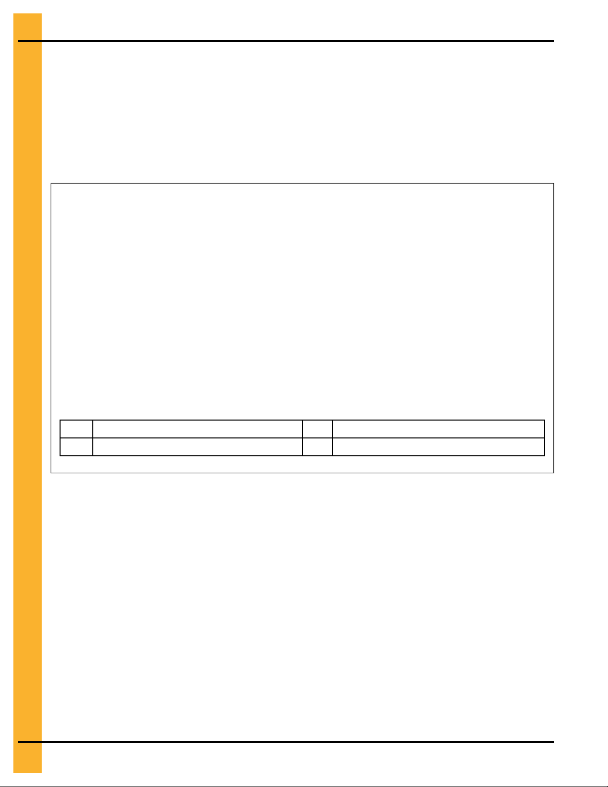
Guidelines for Placement of the Decal Sidewall Sheet
Use the following as a general guideline the proper decal sheet placement.
NOTE: Refer to the stiffener to sidewall attachment detail and specific gauge sheet for the bin. The decal
sheets are located in the first ring from the top. They are to be spaced evenly around the diameter
of the bin.
Figure 2-1 Decal sidewall sheet
NOTE: Stiffener locations are represented with thick lines.
PNEG-4336 36 Ft. Diameter 40-Series Bins
21
Chapter 2: General Overview
Anchor Bolt Detail
The following is the minimum requirement for anchoring of standard tanks.
• 3/4 in. diameter anchor bolt (A) is the minimum allowed, 1 in. diameter anchor bolt (A) is the
minimum with sidedraw flume system.
• Exposed anchor bolt thread height (B) is 5 in. (12.7 cm).
• Overall anchor bolt length (C) for 3/4 in. and 1 in. diameter anchor bolt is 18 in. (45.72 cm).
Figure 2-2 Anchor bolt example (3/4 in. diameter anchor bolt shown)
A Anchor bolt C
Anchor bolt thread height
B
Anchor bolt length
22
PNEG-4336 36 Ft. Diameter 40-Series Bins

Chapter 2: General Overview
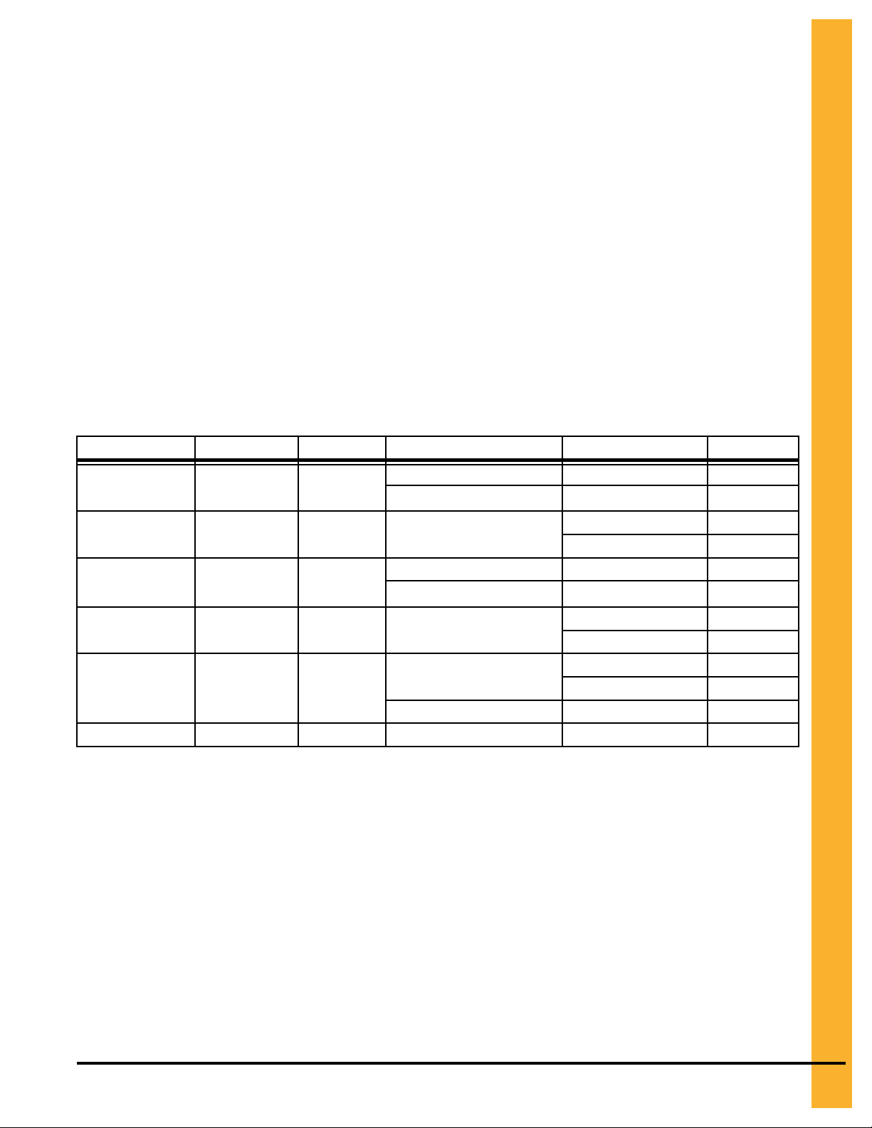
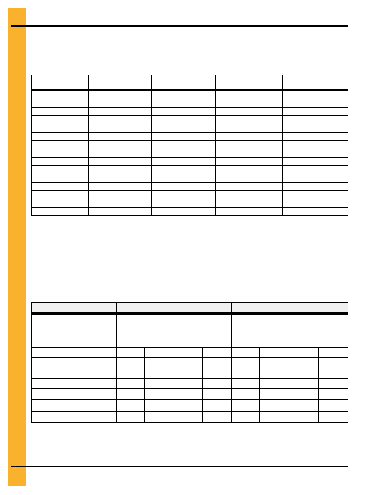
Anchor Bolt Charts
Prior to setting any anchor bolts, you must be sure to have the correct anchor bolt placement. This is very
critical for stiffener alignment during bin erection.
NOTE: Refer to proper chart to find the anchor chord dimensions that correspond to the bin that is being
built.
Scribe the radius location of the anchor bolts by using a center stake and a straight 2 x 4. Along the
scribed radius, start with one anchor bolt and work counterclockwise to locate one quarter of the anchor
bolts then clockwise to locate another quarter of the anchor bolts. Working off of the last anchor bolts in
each quarter, locate the remaining anchor bolts in the last two quarters.
Figure 2-3 Anchor bolt chords for 36 ft. diameter 2-post bin
Radius Location of Bolt (B)
ft and in
18 – 3-5/8 5.578 24
Chord (A)
1 4 – 9-3/8 1.457
2 9 – 5-3/4 2.889
3 14 – 1/8 4.270
4 18 – 3-11/16 5.580
5
6 25 – 10-11/16 7.891
PNEG-4336 36 Ft. Diameter 40-Series Bins
m
Length
ft and in
22 – 3-7/16 6.793
Anchor Bolt Quantity
m
23

NOTES
24
PNEG-4336 36 Ft. Diameter 40-Series Bins
3 Hardware requirements
Topics Covered in this Chapter
▪ Bolt and Nut Pairings
▪ Hardware for Sidewall Sheets on 4 in. Corrugation Bins
▪ Bolt Torque Specifications
▪ Identifying Bolt Grades
▪ Bolt Identification
▪ Color Chart for Bin Hardware Bucket Lids
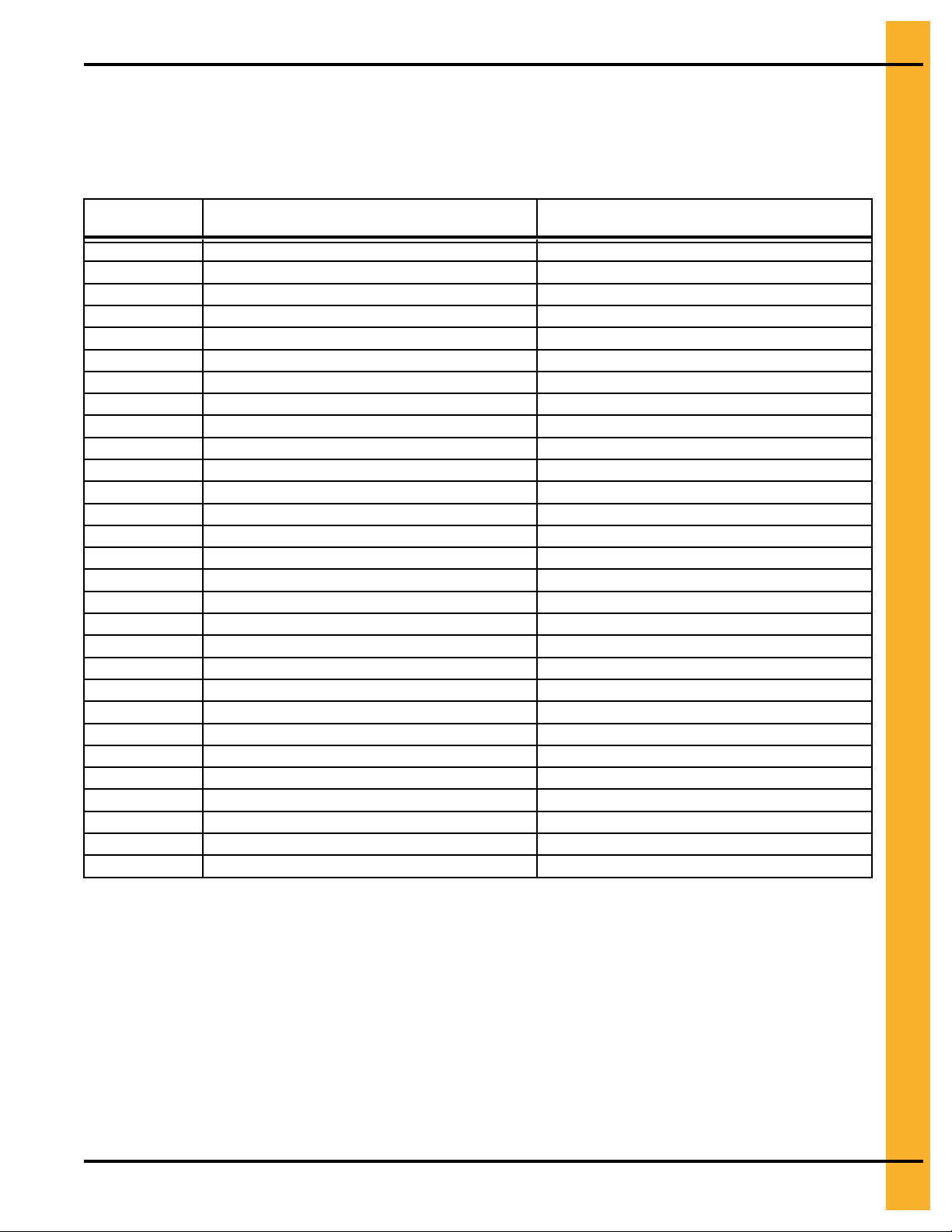
Bolt and Nut Pairings
This chart lists the correct nut to use with each size of bolt.
Nut Part #
S-396 5/16 YDP
S-3611 5/16 YDP
S-10268 5/16 JS
S-456 3/8 YDP Hex
S-9426 3/8 JS
S-9281 7/16 JS Hex 7/16 x 3-1/4 S-10261
Nut Size (in.) Type Hex or Flanged (Bolt) Bolt Size (in.)
Hex 5/16 x 1-1/4 S-7483
Flanged
Flanged
Hex 5/16 x 1-1/4 S-7483
Flanged
Flanged
Hex
5/16 x 1 S-10260
5/16 x 1 S-10260
5/16 x 1-1/4 S-7483
5/16 x 1 S-10260
3/8 x 1 S-7487
3/8 x 1-1/2 S-7488
3/8 x 1 S-7485
3/8 x 1-1/2 S-7488
3/8 x 1 S-7487
Bolt Part #
PNEG-4336 36 Ft. Diameter 40-Series Bins
25
Chapter 3: Hardware requirements
Hardware for Sidewall Sheets on 4 in. Corrugation Bins
Reference the chart for hardware requirements for 2-post sidewall sheet connections on bins 30 to 72 ft.
in diameter commercial stiffened bins.
Table 3-1 Hardware for 2-Post Sidewall Sheets on 4 in. Corrugation Bins 30 to 72 ft. in Diameter
Gauge
20
19
18
17
16
15
14
13
12
11
10
9
8
13L
12L
Horizontal Seam
Bolt Size (Quantity)
5/16 x 1 (8) 5/16 x 1 (42) 3/8 x 1 (22) 5/16 x 1 (2)
5/16 x 1 (8) 5/16 x 1 (42) 3/8 x 1 (22) 5/16 x 1 (2)
5/16 x 1 (8) 5/16 x 1 (42) 3/8 x 1 (22) 5/16 x 1 (2)
5/16 x 1 (8) 5/16 x 1 (42) 3/8 x 1 (22) 5/16 x 1 (2)
5/16 x 1 (8) 5/16 x 1 (42) 3/8 x 1 (22) 5/16 x 1 (2)
5/16 x 1 (8) 5/16 x 1 (42) 3/8 x 1 (22) 5/16 x 1 (2)
3/8 x 1 (20) 3/8 x 1 (42) 3/8 x 1 (22) 3/8 x 1 (2)
3/8 x 1 (20) 3/8 x 1 (42) 3/8 x 1 (22) 3/8 x 1 (2)
3/8 x 1 (20) 3/8 x 1 (42) 3/8 x 1 (22) 3/8 x 1 (2)
3/8 x 1 (20) 3/8 x 1 (63) 3/8 x 1 (22) 3/8 x 1 (2)
3/8 x 1 (20) 3/8 x 1 (63) 3/8 x 1 (22) 3/8 x 1 (2)
3/8 x 1 (20) 3/8 x 1 (63) 3/8 x 1.5 (22) 3/8 x 1.5 (4)
3/8 x 1 (20) 3/8 x 1 (63) 3/8 x 1.5 (22) 3/8 x 1.5 (4)
3/8 x 1.5 (20) 3/8 x 1.5 (63) 3/8 x 1.5 (22) 3/8 x 1.5 (4)
3/8 x 1.5 (20) 3/8 x 1.5 (63) 3/8 x 1.5 (22) 3/8 x 1.5 (4)
Vertical Seam Bolt
Size (Quantity)
Stiffener to Sidewall
Bolt Size (Quantity)
Overlap Seam Bolt
Size (Quantity)
Bolt Torque Specifications
The specification torque table below will help the installer determine how tight a specific bolt must be. A
bolt that has been over tightened can be just as dangerous as one that hasn't been tightened enough.
IMPORTANT: Bolts should not be tightened in excess of the torque specifications chart listed below.
Bolt
Sealing Joints
(joints with seal-
ing washers)
ft-lb N-m ft-lb N-m ft-lb N-m ft-lb N-m
5/16-18 JS Gr 8 with seal 20 27
3/8 -16 JS Gr 8 with seal 30 41
7/16-14 JS Gr 8 with seal 50 68
3/8–16 YDP Gr 8 flanged — —
7/16–14 YDP Gr 8 flanged — —
1/2-13 YDP Gr 8 flanged — —
Minimum Torque Maximum Torque
Structural Joints
(joints without
sealing washers)
— —
— —
— —
40 54
65 88
100 135
Sealing Joints
(joints with seal-
ing washers)
25 34
35 47
60 81
— —
— —
— —
Structural Joints
(joints without
any sealing
washers)
— —
— —
— —
45 61
72 97
110 149
26
PNEG-4336 36 Ft. Diameter 40-Series Bins
Chapter 3: Hardware requirements
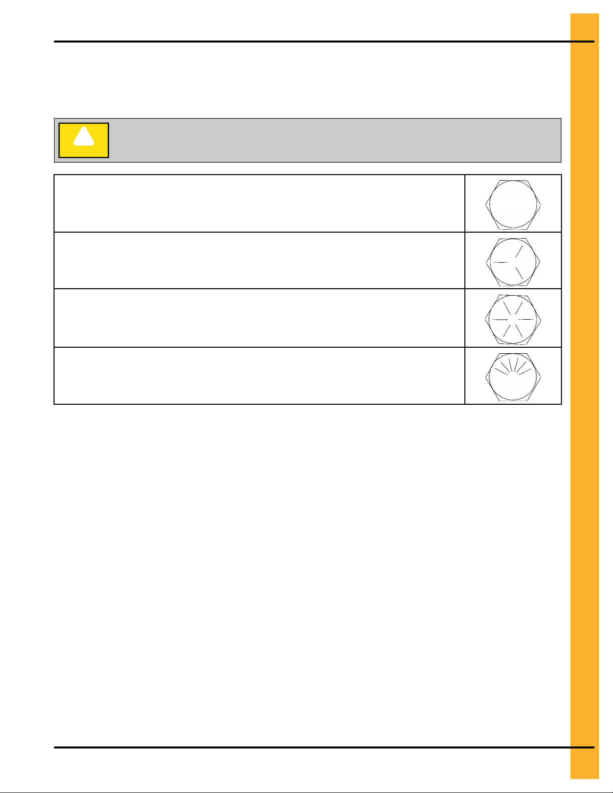
Identifying Bolt Grades
Bolts are identified by grade (or hardness), the grade can be identified by the markings on the head of the
bolt. These markings will be in the form of slash marks and patterns. Use the following as a guide to determine the correct bolt grade.
Under no condition shall any other bolts be substituted for those supplied by GSI.
CAUTION
Grade 2 Bolts
Grade 2 bolts are designated with a plain head and are not used in GSI grain bins.
Grade 5 Bolts
Grade 5 bolts are designated by three slash marks on the head. All 5/16 inch diameter
bolts are to be grade 5 or higher.
Grade 8 Bolts
Grade 8 bolts are designated by six slash marks evenly spaced out around the head of the
bolt. All 3/8, 7/16, and 1/2 inch diameter bolts are to be grade 8 or grade 8.2.
Grade 8.2 Bolts
Grade 8.2 bolts are designated by six slash marks on the head in a sunrise pattern. All 3/8,
7/16, and 1/2 inch diameter bolts are to be grade 8 or grade 8.2.
NOTE: Refer to 4.00 in. tank bolting requirements for complete bolt usage.
PNEG-4336 36 Ft. Diameter 40-Series Bins
27
Chapter 3: Hardware requirements
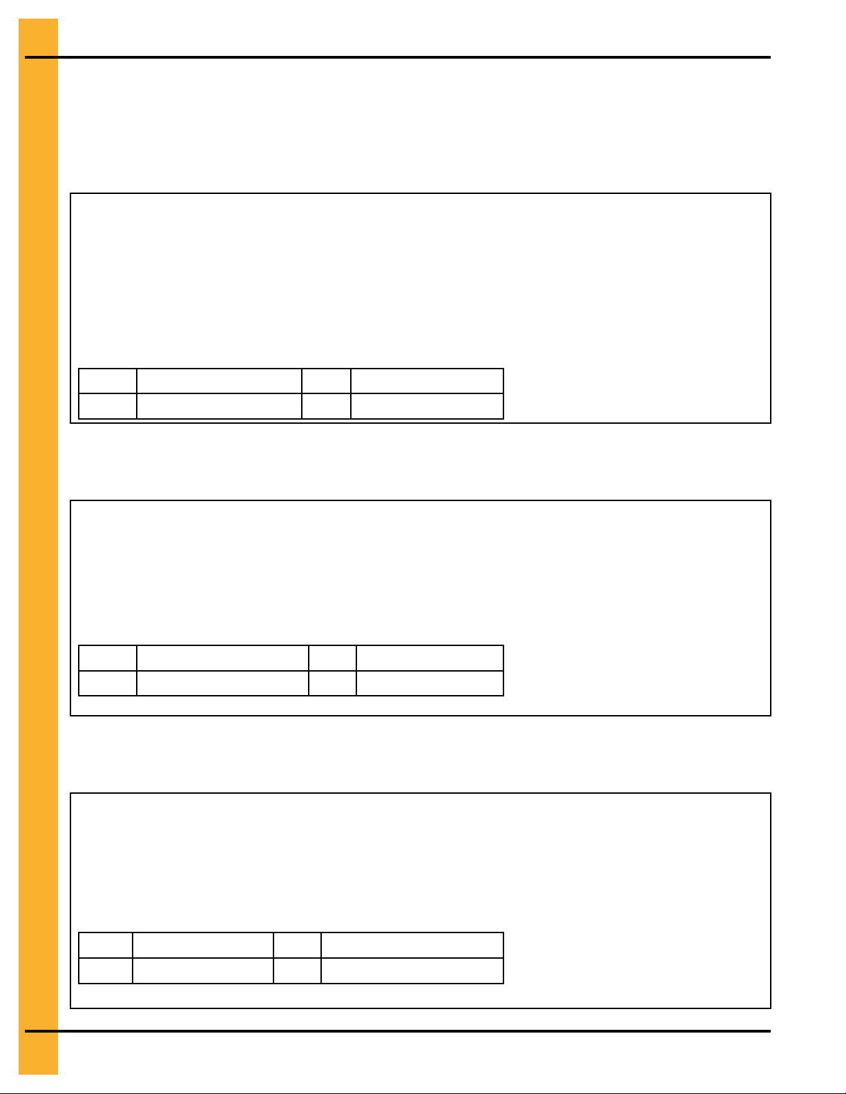
Bolt Identification
Use the following information to identify the bolts and where each must be used during installation.
Bolt S-10260
An S–10260 is a 5/16 x 1 in. JS bolt that is pre-assembled with a sealing washer.
Bolt (S-10260) is used in the following locations:
• Use to connect horizontal, vertical and overlap seams on
15 gauge to 20 gauge sidewall connections.
• Use to connect roof panels together where they overlap.
• Use when connecting eave angle to sidewall sheet.
• The color of the bucket lid is lime green.
• Use to attach roof panels to flashing on all bins that are 48 ft.
diameter and smaller.
A
B
1.300 in. (3.30 cm )
1.000 in. (2.54 cm)
C Grade 8
D Grade 8.2
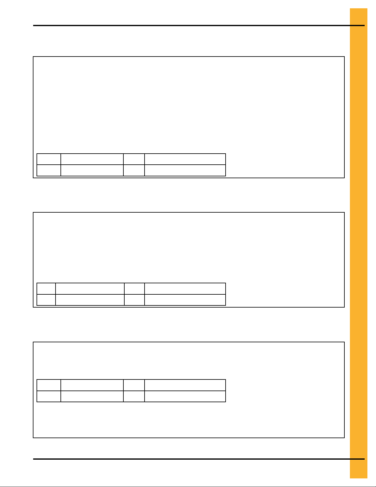
Bolt S-7483
An S–7483 is a 5/16 x 1-1/4 in. JS bolt pre-assembled with a sealing washer.
Bolt (S-7483) is used in the following locations:
• Use in base angle to sidewall connection.
• Use in flashing to sidewall connection.
• Use in Accessories.
• The color of the bucket lid is black.
A
B
1.437 in. (3.64 cm )
1.250 in (3.17 cm)
C Grade 8
D Grade 8.2
Bolt S-7485
An S–7485 is a 3/8 x 1 in. JS hex bolt with flanged head and without a sealing washer.
28
Bolt (S-7485) is used in the following locations:
• Use to splice the stiffeners together on the flanges. (A flange nut
is used on the nut side of the connection.)
• Use to splice the laminated stiffeners together. (A flange nut is
used on the nut side of the connection.)
• The color of bucket lid is light green.
1.350 in. (3.43 cm)
A
1.000 in. (2.54 cm)
B
C Grade 8
D Grade 8.2
PNEG-4336 36 Ft. Diameter 40-Series Bins
Chapter 3: Hardware requirements
Bolt S-7487
An S–7487 is a 3/8 x 1 in. JS bolt that is pre-assembled with a sealing washer.
Bolt (S-7487) is used in the following locations:
• Use in sidewall to stiffener connections for 20 gauge to 15
gauge.
• Use in all sidewall connections for 14 gauge through 10 gauge
sidewall to sidewall sheets.
• Use for horizontal and vertical seam connections for 9 gauge
through 8 gauge sidewall sheets.
• Color of bucket lid is grey.
NOTE: Do not use to splice the stiffeners together on the flanges
where they connect to each other or the splice plates.
1.350 in. (3.43 cm)
A
1.000 in. (2.54 cm)
B
C Grade 8
D Grade 8.2
Bolt S-7488
An S-7488 is a 3/8 x 1-1/2 in. JS bolt that is pre-assembled with a sealing washer.
Bolt (S-7488) is used in the following locations:
• Use in all stiffener to sidewall and overlap connections where
the sidewall is 9 gauge or thicker.
• Use in all sidewall connections that are 13 gauge laminated.
NOTE: Do not use in flanges where the splice plate bolts to the stiff-
eners. Sealing washers should not be used for these
connections.
A
3.645 in. (9.26 cm) C Grade 8
B
3.250 in. (8.26 cm)
D
Grade 8.2
Bolt S-10261
An S-10261 is a 7/16 x 3-1/4 in. JS bolt that is pre-assembled with a sealing washer.
Bolt (S-10261) is used in the following locations:
• Use in wind ring splice and over pipe connections.
• Lid color of bucket is natural (clear).
3.645 in. (9.26 cm)
A
3.250 in. (8.26 cm)
B
PNEG-4336 36 Ft. Diameter 40-Series Bins
C Grade 8
D Grade 8.2
29
Chapter 3: Hardware requirements
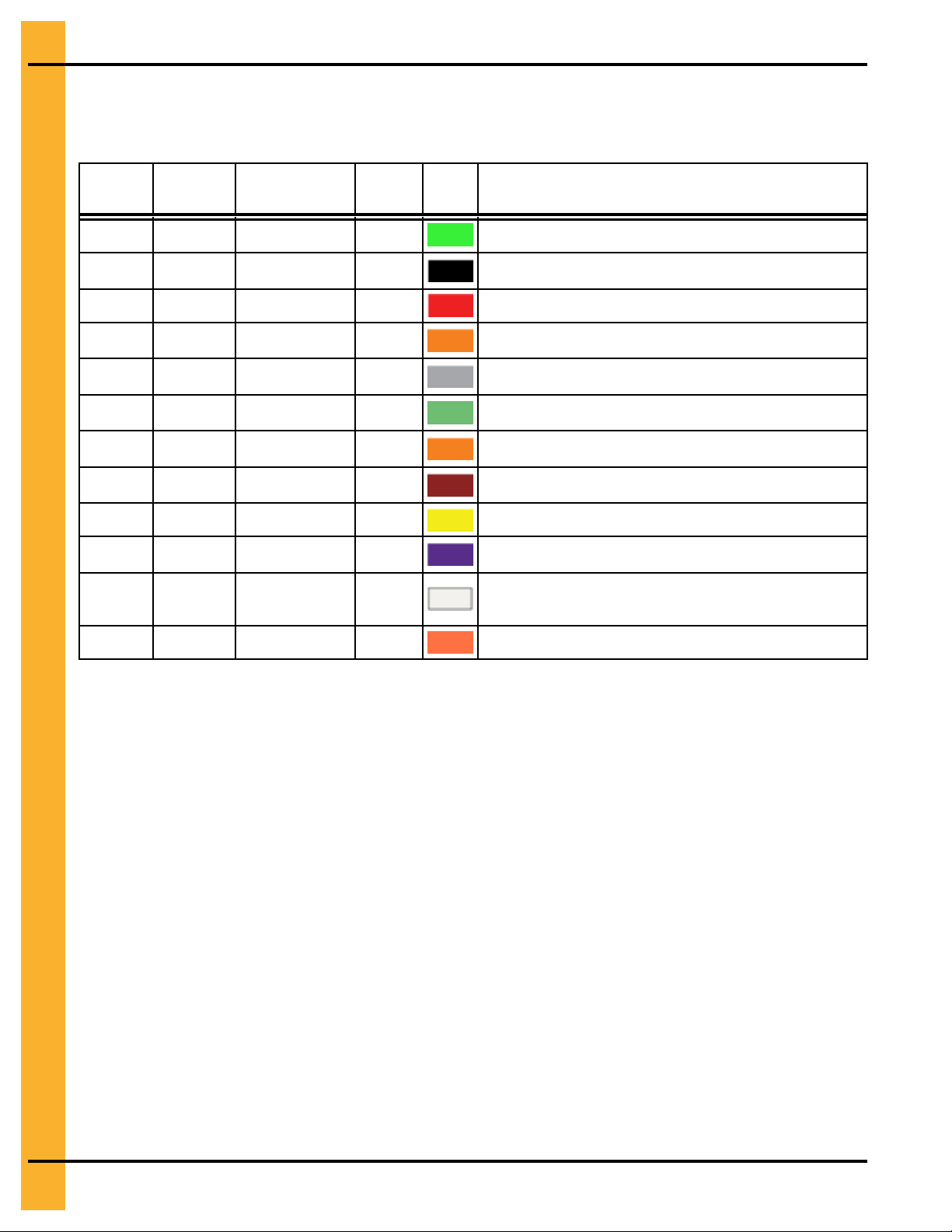
Color Chart for Bin Hardware Bucket Lids
For ease of identification, hardware is separated and identified by buckets with color coded lids. Use the
following chart to help identify the correct hardware.
JS Part
#
S-10260 NA Lime Green 1250
S-7483 NA Black 1000
NA S-396 Red 5000
S-10268 S-3611 Gold NA
S-7487 NA
S-7485 NA
S-7488 NA
S-7486 NA Dark Brown 700
NA S-456 Yellow 4000
S-9426 NA
S-10261 NA
S-9281 NA
YDP Part
#
Color
Grey
Light Green
Orange
Dark Purple
Natural (Clear)
Fire Orange
Bucket
Count
850
1000
650
2500
200
1500
Lid
Color
Description
5/16 x 1 in. bolt pre-assembled with sealing washer
5/16 x 1-1/4 in. bolt pre-assembled with sealing washer
5/16 in. hex nut
5/16 in. flange nut
3/8 x 1 in. bolt pre-assembled with sealing washer
3/8 x 1 in. flange bolt without sealing washer
3/8 x 1-1/2 in. bolt pre-assembled with sealing washer
3/8 x 1-1/2 in. flange bolt without sealing washer
3/8 in. hex nut
3/8 in. hex flanged nut
7/16 x 3-1/4 in. flange bolt pre-assembled with sealing
washer
7/16 in. hex nut
30
PNEG-4336 36 Ft. Diameter 40-Series Bins
 Loading...