

GSi 1100, 1200, 1200S, CFAB- 2 FAN, CFAB-1 FAN Installation Manual
...
Single-Module Portable Dryer
Models:
1100, 1200, 1200S
CFAB-1 FAN, CFAB- 2 FAN, C2100A
Installation Guide
PNEG-1891
Version 3.1
Date: 09-09-16
PNEG-1891

All information, illustrations, photos, and specifications in this manual are based on the latest
information available at the time of publication. The right is reserved to make changes at any
time without notice.
2
PNEG-1891 Portable Dryers

Contents
Chapter 1 Safety Precautions ....................................................................................................................5
Safety Guidelines for Portable Dryers ...........................................................................................5
Cautionary Symbol Definitions......................................................................................................6
Safety Decals for Portable Dryers .................................................................................................7
Chapter 2 Installation Guidelines............................................................................................................. 11
Guidelines for Transporting a Portable Dryer ............................................................................... 11
Guidelines for Placing a Portable Dryer.......................................................................................12
Recommendations for a Single-Module Dryer Foundation ............................................................12
Chapter 3 Dryer Supports........................................................................................................................ 15
Guidelines for Supporting the Dryer with Concrete Blocks ............................................................ 15
Guidelines for Supporting the Dryer with Leg Stands....................................................................16
Leg Stand Spacing....................................................................................................................16
Installing Front and Rear Anchor Plates ......................................................................................17
Installing a Leg Stand to the Dryer Basket Corner ........................................................................ 18
Installing a Leg Stand Along the Dryer Frame..............................................................................19
Installing the Leg Stands Behind the Hitch Frame ........................................................................ 21
Chapter 4 Hitch Ladder............................................................................................................................ 23
Hitch Ladder Packages..............................................................................................................23
Installing the Hitch Ladder Support Bracket to the Hitch Channel .................................................. 24
Installing the Ladder Standoff Bracket to the Hitch Ladder Support Bracket ...................................25
Installing the Ladder to the Ladder Standoff Brackets...................................................................26
Installing the End Cap to the Ladder ........................................................................................... 26
Chapter 5 Rear Access Ladder ................................................................................................................29
Installing the Rear Ladder Support Brackets................................................................................ 29
Installing the Ladder Standoff Brackets to the Rear Ladder Support Brackets ................................31
Chapter 6 Installing the Wet Bin .............................................................................................................. 33
Raising the Load Auger .............................................................................................................33
Securing the Dryer Wet Bin Sides............................................................................................... 35
Installing the Belt Guard and Load Motor..................................................................................... 36
Installing the Drive Sheaves and Belts ........................................................................................ 37
Installing the Belt Guard Cover ................................................................................................... 38
Installing the Grain Intake Hopper............................................................................................... 39
The Parts of the Dryer Wet Bin ...................................................................................................40
Chapter 7 Moisture Sampler .................................................................................................................... 43
Installing the Moisture Sampler .................................................................................................. 43
Blower Cover Assembly Parts (D04–1016).................................................................................. 48
Moisture Sampler Hose Parts (D04–1023) ..................................................................................49
220V Moisture Sampler Blower Wiring Diagram........................................................................... 50
400V Moisture Sampler Blower Wiring Diagram........................................................................... 51
480V Moisture Sampler Blower Wiring Diagram........................................................................... 52
600V Moisture Sampler Blower Wiring Diagram........................................................................... 53
Chapter 8 Power Supply ..........................................................................................................................55
Guidelines for Supplying Adequate Power................................................................................... 55
Installing the Machine-to-Earth Grounding Rod............................................................................55
Guidelines for Powering Auxiliary Conveyors...............................................................................57
Specifications for the Electrical Load on a Portable Dryer ............................................................. 57
Chapter 9 Fuel Supply .............................................................................................................................63
Guidelines for Connecting a Liquid Propane Supply Tank to a Dryer .............................................. 63
Specifications and Recommendations for Liquid Propane ............................................................64
Guidelines for Connecting Natural Gas to a Dryer ........................................................................ 65
Specifications and Recommendations for Natural Gas .................................................................66
PNEG-1891 Portable Dryers
3

Appendix A Dryer Specifications ................................................................................................................67
Specifications for GSI Dryers .....................................................................................................67
Transport and Installation Dimensions for Single-Module GSI Dryers ............................................69
Specifications for FFI Dryers ......................................................................................................71
Transport and Installation Dimensions for Single-Module FFI Dryers.............................................73
Specifications for X-Stream Dryers .............................................................................................74
Transport and Installation Dimensions for Single-Module X-Stream Dryers....................................76
Index .......................................................................................................................................77
GSI Group, LLC Limited Warranty ........................................................................................... 79
4
PNEG-1891 Portable Dryers

1 Safety Precautions
Topics Covered in this Chapter
▪ Safety Guidelines for Portable Dryers
▪ Cautionary Symbol Definitions
▪ Safety Decals for Portable Dryers
Safety Guidelines for Portable Dryers
Safety guidelines are general-to-specific rules that promote safe practices in the grain drying environment
and which must be respected at all times. Save these safety guidelines for future reference.
Make sure to read these safety guidelines carefully prior to installing, operating, or
CAUTION
Operation
• Read and fully understand this user guide before attempting to operate the grain dryer.
servicing your grain dryer.
• Never operate the grain dryer with its safety guards removed.
• Never operate the grain dryer by bypassing any safety device.
• Never exceed the maximum recommended drying temperature.
• Do not operate the grain dryer in an area where combustible material might be drawn into the fan.
• The operating and safety recommendations in this guide pertain to common cereal grains, as indicated. When drying other types of grain or products, contact the GSI Group, LLC for additional
recommendations.
Servicing
• The power supply must be disconnected when servicing electrical components. Always use
extreme caution when measuring voltage or performing procedures that require the dryer to be
turned on.
• Before attempting to remove and reinstall a fan’s propeller, make sure to read the recommended
procedure. If you are unsure about performing this procedure or cannot locate it, contact the GSI
Group, LLC before proceeding.
Cleanliness
• Keep the grain dryer clean at all times.
• Do not allow fine material to accumulate in the plenum chamber.
PNEG-1891 Portable Dryers
5

Chapter 1: Safety Precautions
• An unclean plenum increases resistance to airflow, increases drying time, reduces drying efficiency,
and creates a fire hazard.
• Always keep the area around the fan’s air inlet clear of any obstacles and combustible material.
Augers/Auxiliary Conveyors
Always use extreme caution when working around augers and auxiliary conveyors
CAUTION
• Always keep auger drive belts adequately tensioned to prevent slippage.
• Make sure that the technical specifications and capacities of the auxiliary conveyors are matched to
those of the dryer augers.
because they can start automatically.
Burners/Gas Lines
• Regularly check for leaks at all gas line connections. If any leaks are detected, do not operate the
grain dryer. Shut off the main power and repair the leaks before operating. Gas lines must be
replaced regularly as required by the local gas regulations for your area.
• Routinely check for potential gas plumbing leaks. Check the liquid propane vaporizer for contact
with the burner vanes.
• Never use an open flame to locate gas leaks. Pour a solution of soap and water over the gas pipe
joints and connections, and check for the appearance of small bubbles.
• Set the pressure regulator to avoid applying excessive gas pressure to the burner during ignition or
when the burner is on.
• Do not use flammable or combustible materials in the dryer’s vicinity because explosive vapors can
be drawn into the fan and ignite.
• Always use extreme caution when working around high-speed fans and gas burners because they
can start automatically.
Cautionary Symbol Definitions
Cautionary symbols appear in this manual and on product decals. The symbols alert the user of potential
safety hazards, prohibited activities and mandatory actions. To help you recognize this information, we
use the symbols that are defined below.
Table 1-1 Description of the different cautionary symbols
Symbol Description
This symbol indicates an imminently hazardous situation which, if
not avoided, will result in serious injury or death.
This symbol indicates a potentially hazardous situation which, if not
avoided, can result in serious injury or death.
This symbol indicates a potentially hazardous situation which, if not
avoided, can result in minor or moderate injury.
6
PNEG-1891 Portable Dryers

Table 1-1 Description of the different cautionary symbols (cont'd.)
Symbol Description
This symbol is used to address practices not related to personal
injury.
This symbol indicates a general hazard.
This symbol indicates a prohibited activity.
This symbol indicates a mandatory action.
Chapter 1: Safety Precautions
ST-0005–2
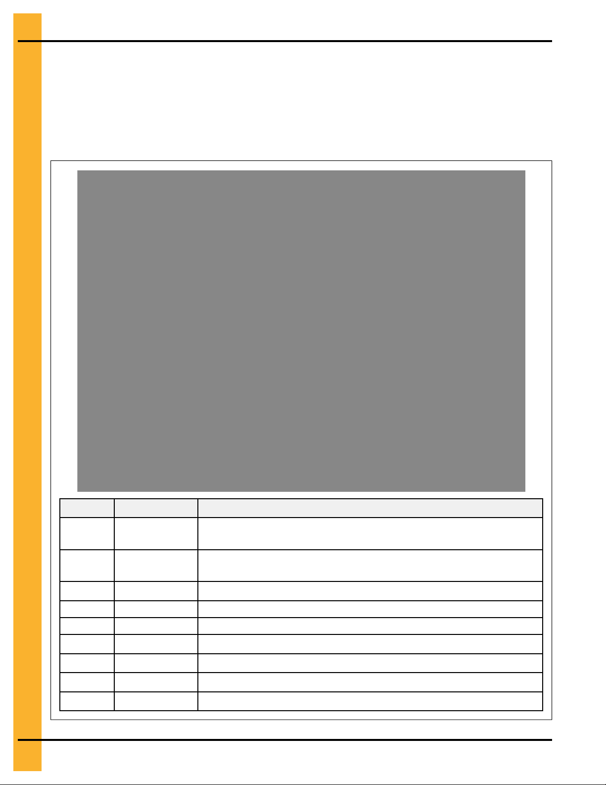
Safety Decals for Portable Dryers
The safety decals on your grain dryer are safety indicators which must be carefully read and understood
by all personnel involved in the installation, operation, service, and maintenance of the grain dryer.
Table 1-2 Description of the grain dryer’s decals
Decal Decal No. Location
This decal appears:
• On the lid of the fan/heater control box
DC-1948
• On the front of the fan/heater control box
• Inside the dryer’s upper control box
This decal appears:
• On the bottom auger belt guard
• On the front bearing plate (visible when the bottom
auger belt guard is removed)
PNEG-1891 Portable Dryers
DC-1944
• At the rear of the dryer (for dryers equipped with the
front discharge option)
• On the top auger belt guard
• On the inside belt guard body (visible when the top
auger belt guard is removed)
7

Chapter 1: Safety Precautions
Table 1-2 Description of the grain dryer’s decals (cont'd.)
Decal Decal No. Location
This decal appears:
• On the bottom auger belt guard
DC-1945
DC-1946
DC-1947
• On the front bearing plate (visible when the bottom
auger belt guard is removed)
• At the rear of the dryer (for dryers equipped with the
front discharge option)
This decal appears:
• On the inside of the rear plenum access door
• On the outside of the rear plenum access door
This decal appears:
• Twice on the front end panel, below the fan/heater
• Twice on the rear end panel, below the rear access
door
• On the auger discharge box
DC-1943
• On the inside of the auger discharge box’s flapper lid
(next to the discharge mercury switch)
• Inside the rear access door, on the rear plenum closure door (inside the plenum)
This decal appears:
• Inside the fan/heater control box
• On the door of the dryer’s upper control box
8
PNEG-1891 Portable Dryers

Table 1-2 Description of the grain dryer’s decals (cont'd.)
Decal Decal No. Location
DC-1949
DC-1959
Chapter 1: Safety Precautions
This decal appears on the fan/heater access door
This decal appears on the fan/heater access door
This decal appears on each of the metering roll access
doors
DC-1950
This decal appears on the hitch tongue
DC-1956
This decal appears on the hitch tongue
DC-1954
Replacing Decals
All decals located on your grain dryer must remain legible and clearly visible at all times. To replace a
damaged or missing decal, contact us to receive a free replacement.
GSI Decals
1004 E. Illinois St.
Assumption, IL. 62510
Tel: 1–217–226–4421
PNEG-1891 Portable Dryers
9

NOTES
10
PNEG-1891 Portable Dryers

2 Installation Guidelines
Topics Covered in this Chapter
▪ Guidelines for Transporting a Portable Dryer
▪ Guidelines for Placing a Portable Dryer
▪ Recommendations for a Single-Module Dryer Foundation
Guidelines for Transporting a Portable Dryer
To transport the dryer safely, follow the recommended guidelines and adhere to all state or provincial
towing regulations.
• Refer to Appendix A for the dryer transportation dimensions.
• Ensure that the hitch height is between 14 and 17 in. (35.6 and 43.2 cm), see Figure 2-1, page 11).
• The hitch bolt must be at least 0.75 in. (1.9 cm) in diameter and securely fastened with a locking nut,
(see Figure 2-2, page 12).
• Use washers to minimize the vertical hitch movement
• Always use a safety chain.
• Dryer must be towed empty and in accordance with applicable state or provincial regulations.
NOTE: NEVER tow dryer with grain or any other material inside of it. Never tow after top modules
have been stacked.
• Recommended tire pressure is 55-60 PSI (3.8 bar) cold.
• Ensure the wheel lug nuts are torqued at 115 to 120 ft-lb (160 Nm).
• Maximum towing speed is 45 mph (70 km/h) or the speed limit, whichever is lower.
• After the first 50 miles (80 km) and every 200 miles (300 km) thereafter, examine the dryer wheel
hub and the spindle temperature immediately after stopping
NOTE: Temperature must not exceed 150° F (65° C) or lubricant will melt.
Figure 2-1 14 and 17 in. (35.6 and 43.2 cm) towing hitch height and safety chain
PNEG-1891 Portable Dryers
11
Chapter 2: Installation Guidelines
Figure 2-2 Hitch bolt with washer used for spacing
A Washers B Locking nut
C 0.75 in. (1.9 cm)
Guidelines for Placing a Portable Dryer
The location of existing equipment and local code requirements must be evaluated before installing the
dryer.
Things to consider when choosing a location:
• Refer to Appendix A for dryer installation dimensions.
• Consult all national and local electrical and gas codes to ensure dryer is located correctly.
• Consider the location of the wet grain supply and dry grain discharge in relationship to the dryer.
• Consider the location of the storage bins and other grain handling equipment in relationship to the
dryer.
• Consider the location of the fuel supply and electrical sources in relationship to the dryer.
• Maintain a minimum distance of at least three feet between the dryer and other structures, otherwise
air flow problems may occur.
12
Do not operate dryer in an area where combustible materials can be drawn into
WARNING
the fans or where load and unload augers can come into contact with power
lines.
Recommendations for a Single-Module Dryer Foundation
A reinforced concrete pad or similar permanent foundation is required to keep the dryer stable during
operation.
Minimum Bag Mix for Concrete Strength per Model Weight
Consider the location of the gas and electrical service locations and how the pipe and the wire need to be
positioned before pouring the concrete.
PNEG-1891 Portable Dryers
Chapter 2: Installation Guidelines
To prevent the dryer from overturning or moving laterally, the dryer must be secured to the foundation
using anchor bolts or cables. Anchor bolts can be cast into the concrete slab and secured to the dryer
legs. The dryer can also be secured using cables and turnbuckles that are fastened to the anchors that
are installed at the edge of the concrete slab.
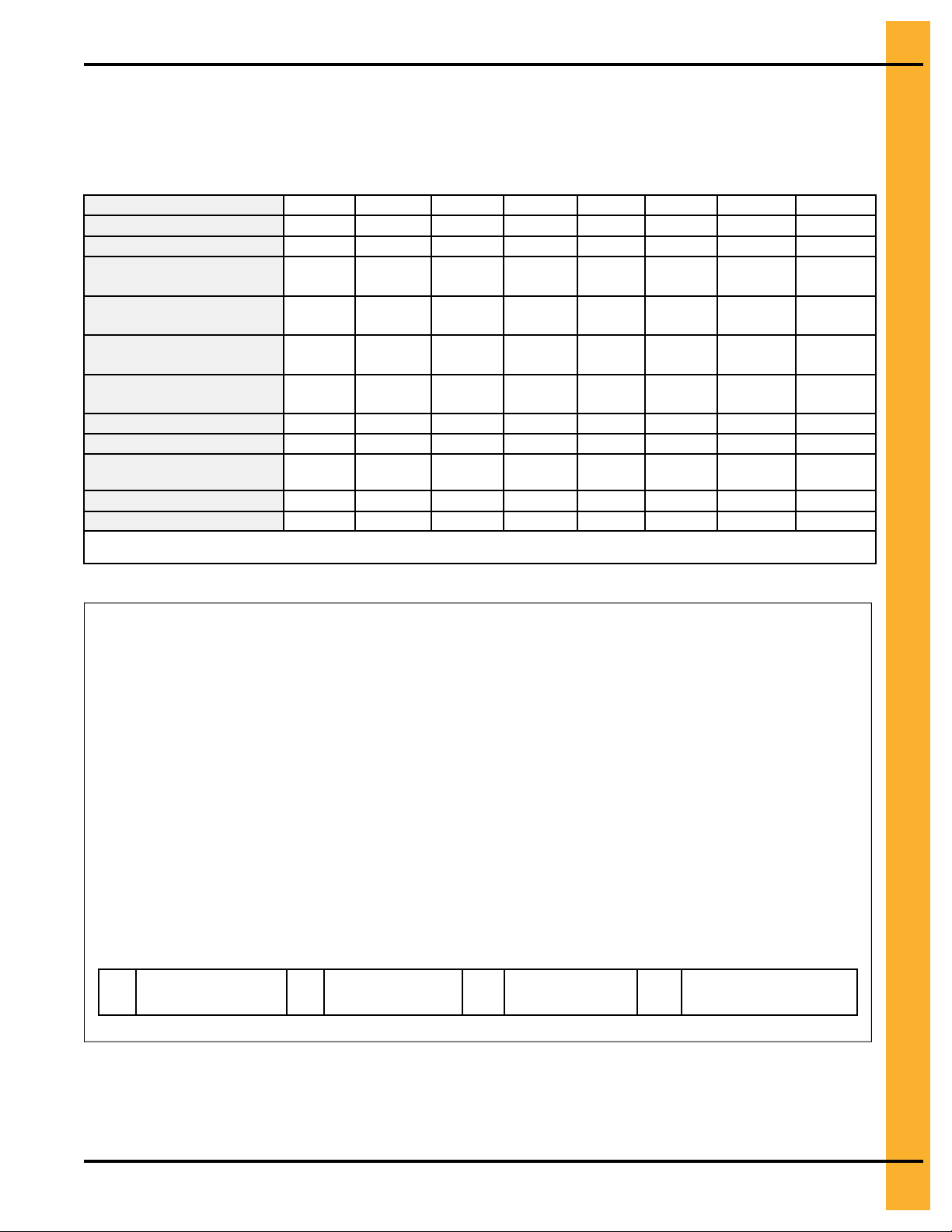
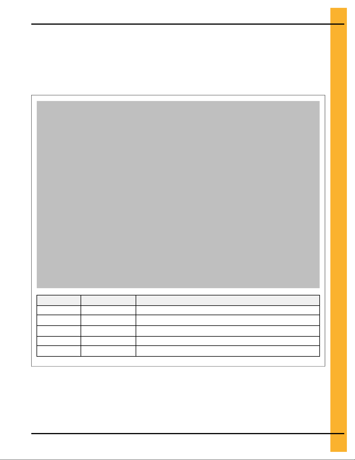
Table 2-1 General reference for concrete materials needed for each size dryer foundation.
Dryer basket length
Concrete pad size (ft x ft)
Concrete pad size (m x m)
Concrete yards (meters)
Quantity of reinforcing rods
20 in. (50.8 cm) each
Wire mesh sq—ft (sq m )
Steel legs (minimum
quantity)
Anchors
Blocks
Feet (Meters) of 2 x 6
boards
Quantity of turnbuckles
Estimated man-hours
Quantities are approximate and requirements might vary due to site elevations.
Setup times do not include site preparations and the pouring of the concrete pad.
8 12 14 16 18 20 22 26
12 x 18 12 x 22 12 x 24 12 x 26 12 x 28 12 x 30 12 x 32 12 x 36
3.7 x 5.5 3.7 x 6.7 3.7 x 7.3 3.7 x 7.9 3.7 x 8.5 3.7 x 9.1 3.7 x 9.8 3.7 x 11
5.9 (5.4) 7.1 (6.5) 7.7 (7.0) 8.3 (7.6) 8.9 (8.1) 9.2 (8.4) 10.1 (9.2)
6 7 7 8 8 8 9 10
20.0
(216)
8 10 12 12 14 14 16 18
4 6 6 6 8 8 8 10
14 18 18 18 22 22 26 30
14 (4.3) 18 (5.5) 18 (5.5) 18 (5.5) 22 (6.7) 22 (6.7) 26 (7.9) 30 (9.1)
4 6 6 6 8 8 8 10
10 14 18 18 20 22 24 28
24.5
(264)
26.7
(288)
29.0
(312)
31.2
(336)
33.4
(360)
35.7
(384)
11.3
(10.3)
40.1
(432)
Figure 2-3 Recommended locations for external equipment
A
Grain discharge
area
B Fill-hopper
C Gas pipe
location
D Electrical service
location
PNEG-1891 Portable Dryers
13
Chapter 2: Installation Guidelines
Figure 2-4 Cross-section of the concrete for single-module dryers
A
6 in. x 6 in. (15.2 cm x 15.2
cm) reinforcing mesh wire
Figure 2-5 Side and rear view of the portable dryer
B
Grade level C 0.5 in. (1.3 cm) number 4 rein-
forcing bar
14
A Turnbuckle B
D
2 in. x 6 in. (5.8 cm x 15.2
cm) board
Front fill option C
E
8 in. X 8 in. X 16 in. (20.3 cm x 20.3 cm x 40.6 cm) concrete
blocks
Front discharge option
PNEG-1891 Portable Dryers

3 Dryer Supports
Topics Covered in this Chapter
▪ Guidelines for Supporting the Dryer with Concrete Blocks
▪ Guidelines for Supporting the Dryer with Leg Stands
▪ Leg Stand Spacing
▪ Installing Front and Rear Anchor Plates
▪ Installing a Leg Stand to the Dryer Basket Corner
▪ Installing a Leg Stand Along the Dryer Frame
▪ Installing the Leg Stands Behind the Hitch Frame
Guidelines for Supporting the Dryer with Concrete Blocks
Before filling the dryer with grain, the dryer frame must be supported with either concrete blocks or leg
stands. If choosing concrete blocks, follow these guidelines for proper installation:
• Place a 2 x 6 or 2 x 8 board between the dryer frame and the concrete blocks to prevent the dryer
frame from fracturing the concrete blocks.
• To prevent the dryer from overturning, it must be secured to the foundation using cables and turnbuckles that are fastened to anchors in the concrete foundation.
• Do not use the wheels as supports. Wheels are for transporting the dryer when it is empty.
• Place concrete blocks six feet apart on each side of the dryer to support the dryer frame.
NOTE: A minimum of one support for every six feet of basket length is required on each side.
• The blocks must be able to support the weight of a dryer that is filled with grain.
• With the hitch tongue removed, place a concrete block under the hitch mount location.
• The hitch assembly and the fan support must remain in place during operation. The hitch assembly
and fan support are not part of the transport tie down assembly.
• Use shims to provide uniform, level support for all blocks.
• The dryer should be 16 in. (40.6 cm) off the concrete pad to accommodate for clean-out and the use
of auxiliary grain handling equipment.
PNEG-1891 Portable Dryers
15
Chapter 3: Dryer Supports
Guidelines for Supporting the Dryer with Leg Stands
Before filling the dryer with grain, the dryer frame must be supported with either concrete blocks or leg
stands. Leg stands are optional and available in seven different sizes to accommodate various dryer
heights.
Leg Stand Height Options
Leg stands are optional and must be ordered separately from your dryer. If you do not have leg stands,
you must support the dryer with concrete blocks.
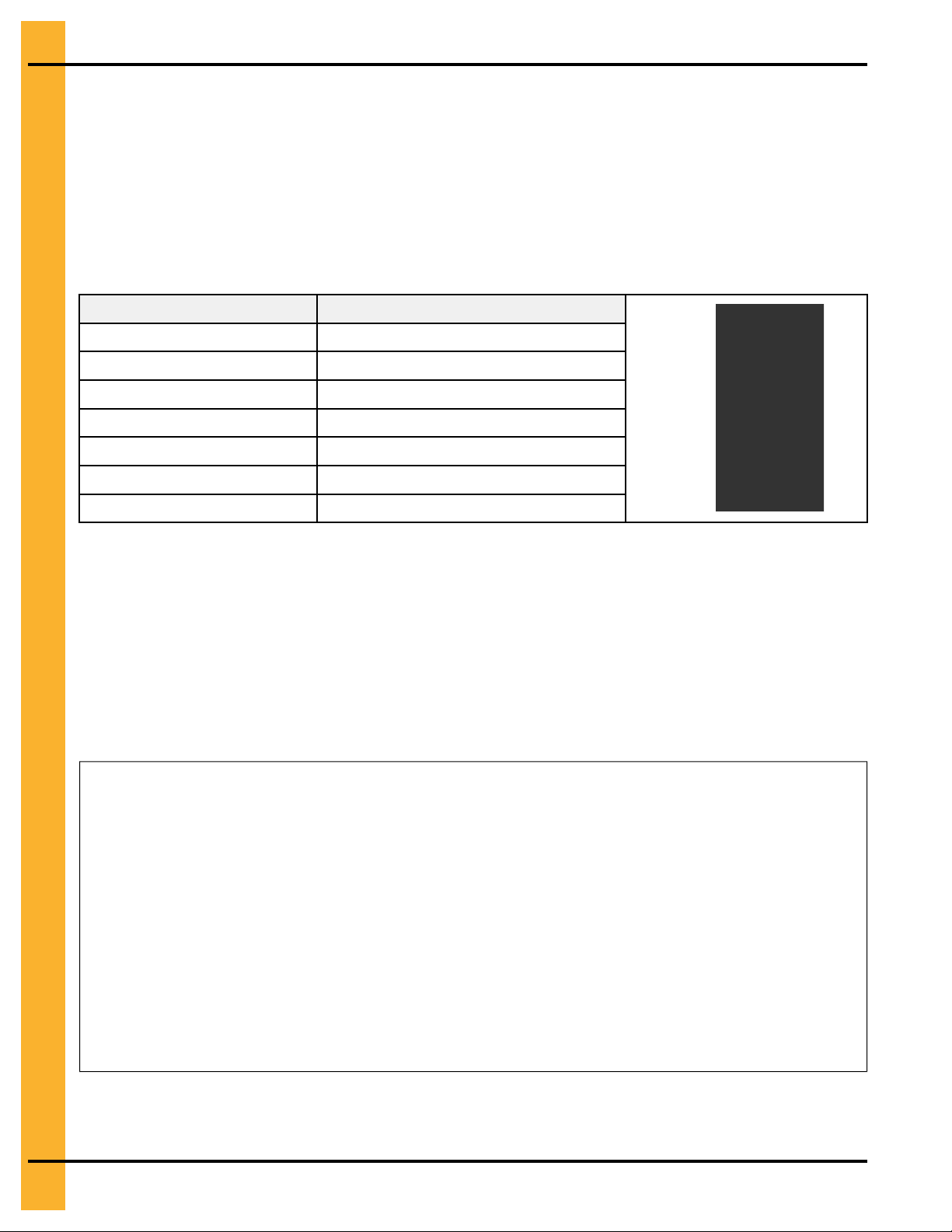
Table 3-1 Leg stand heights
Part number Leg stand height
D01–0408
D01–1046
D01–0398
D01–0399
D01–1047
D01–0582 42 in. (1066.8 mm)
D01–0761 48 in. (1219.2 mm)
16 in. (406.4 mm)
18 in. (457.2 mm)
24 in. (609.6 mm)
30 in. (762 mm)
36 in. (914.4 mm)
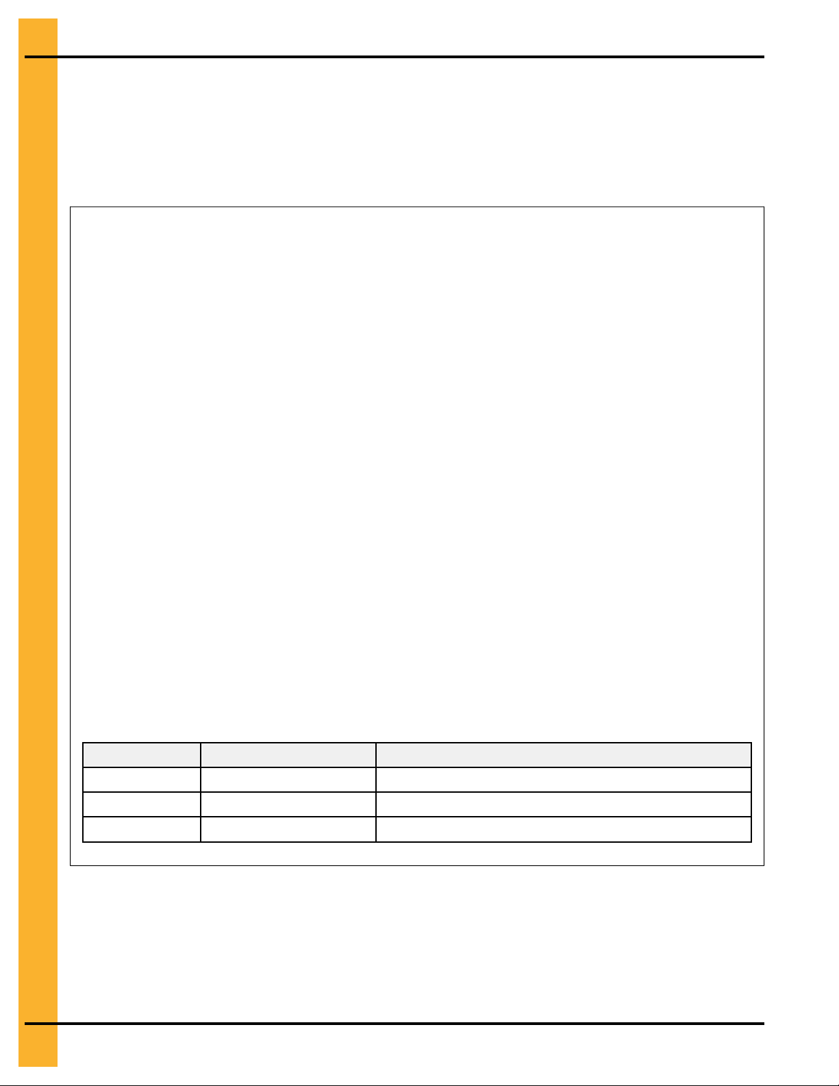
Leg Stand Spacing
Correct leg spacing is important to adequately support the dryer during operation. Incorrect spacing can
result in unstable operating conditions.
Leg Spacing for Standard Dryers
Starting at the back corner of the dryer (A), space legs 4 ft (1.22 m) apart and move towards the front (B).
Spacing between the front legs (C) can be 2 ft (0.61 m) or 4 ft (1.22 m), depending on the length of the
dryer.
Figure 3-1 Leg spacing on a standard dryer
16
Leg Spacing for X-Stream Dryers
PNEG-1891 Portable Dryers

Chapter 3: Dryer Supports
Starting at both the front and back ends of the dryer (A and B), space legs 4 ft (1.22 m) apart working
towards the center of the dryer. Spacing between center legs (C) can be 2 ft (0.61 m) or 4 ft (1.22 m),
depending on the length of the dryer.
Figure 3-2 Leg spacing on an X-Stream dryer
NOTE: The number of dryer legs varies depending on the length of the dryer.
Installing Front and Rear Anchor Plates
To secure the dryer, you must install the front and rear anchor plates to the leg stand bottoms, thereby
enabling the legs to be anchored to the concrete foundation.
1. Use a flange bolt (C) and a flange nut (D) to attach the rear leg anchor plate (A) to the bottom of the
leg stand (E).
2. Position the front leg anchor plate (B) below the rear leg anchor plate (A), and use two flange bolts
(C) and flange nuts (D) to attach the anchor plate to the front of the leg stand (E).
3. Secure the leg stand (E) to the concrete foundation using concrete anchor bolts (not supplied).
Figure 3-3 Leg anchor plate assembly
Callout
A BLK-10057 Rear leg anchor plate
B BLK-10058 Front leg anchor plate
C S-6606 5/16 in. - 18 X 3/4 in. zinc grade 5
Part
number
Description
flange bolt
D
E D01–xxxx
PNEG-1891 Portable Dryers
S-3611 5/16 in. –18 grade 2 flange nut
For leg stand, refer to Leg Stand
Height Options
17

Chapter 3: Dryer Supports
Installing a Leg Stand to the Dryer Basket Corner
If not using concrete blocks, you must install leg stands to the dryer frame at the dryer basket corners to
support the dryer.
What You Should Know
The additional width of the hitch bracket requires the use of an extra shim to install the legs located at the
dryer frame corners.
To install a leg stand to the dryer basket corner:
1. Remove the two existing bolts and nuts from the dryer frame corner (E and F).
2. Align the holes in leg stand (H) with the holes in the dryer frame corner, and fasten in place using the
bolts and nuts that were previously removed (E and F).
3. Align the top hole in the leg stand with the hole in the basket corner leg (G).
4. Fasten the legs together using bolt (B), washer (C), two shims (A), and nut (D).
18
PNEG-1891 Portable Dryers
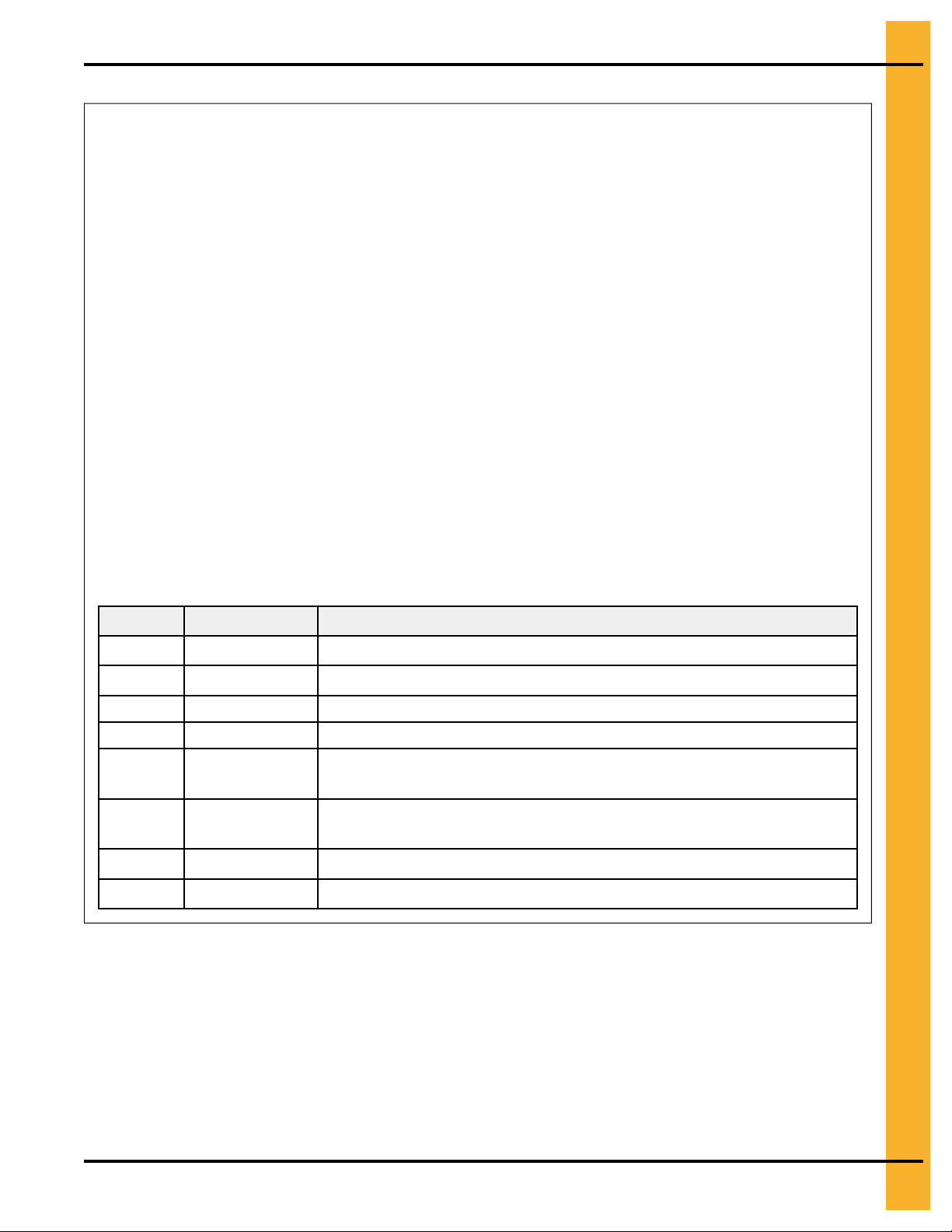
Figure 3-4 Installing a leg stand to the dryer basket corner
Chapter 3: Dryer Supports
Callout
A D01–1221 Shim dryer stand to dryer
B
C S-2121 1/2 in. X 1 3/8 in. flat washer
D
E S-3883 Original bolts installed on dryer (1/2 in. - 13 X 1 3/4 in. YDP grade 8
F
G D01–0007 Basket corner leg
H D01–xxxx For leg stand, refer to Leg Stand Height Options
Part number Description
S-3883 1/2 in. - 13 X 1 3/4 in. YDP grade 8 HHTB bolt
S-8315 1/2 in. - 13 zinc lock nut
HHTB bolt)
S-6493 Original nuts installed on dryer (1/2 in. - 13 zinc grade 2 deformed
lock nut)
Installing a Leg Stand Along the Dryer Frame
If not using concrete blocks, you must install leg stands to the dryer frame to support the dryer.
1. Remove the two bolts and nuts from the dryer frame at the location where the leg stand is to be
installed (A and B).
PNEG-1891 Portable Dryers
19
Chapter 3: Dryer Supports
2. Align the holes in the leg stand (G) with the holes in the dryer frame, and fasten in place using the
bolts and nuts that were previously removed (A and B).
3. Align the top hole in the leg stand (G) with the hole in the basket leg (F).
4. Fasten the legs together using a bolt (E), shim (C), and nut (D).
5. For a secure fit, use the shim plates (H) to make any minor adjustments to the leg height.
Figure 3-5 Installing leg stands along dryer frame
20
Callout Part number Description
A
S-3883 Original bolts installed on dryer (1/2 in. - 13 X 1 3/4 in. YDP grade 8
HHTB bolt)
B S-6493 Original nuts installed on dryer (1/2 in. - 13 zinc grade 2 deformed
lock nut)
C D01–1221 Shim dryer stand to dryer
NS S-2121 1/2 in. X 1 3/8 in. flat washer
D S-8315 1/2 in. -13 zinc lock nut
E S-3728 1/2 in. - 13 X 1 1/2 in. YDP grade 8 or 8.2 HHTB bolt
F D01–0007 Basket corner leg
G D01–xxxx For leg stand, refer to Leg Stand Height Options
H
FC-42077 Shim plate
PNEG-1891 Portable Dryers
Chapter 3: Dryer Supports
Installing the Leg Stands Behind the Hitch Frame
Use leg stands behind the hitch frame to appropriately support the dryer.
1. Position the leg stands (E) behind the hitch frame, and align them with the holes in the rear hitch
cross channel (D).
2. Fasten the legs to the channel using two bolts (B), four washers (C), and two nuts (A) per each leg.
Figure 3-6 Installing leg stands to the hitch assembly
Callout
A
B
C S-2121 1/2 in. X 1 3/8 in. type A plated flat washer
D D01–2481 Rear hitch cross channel
E D01–xxxx
PNEG-1891 Portable Dryers
Part number Description
S-8315 1/2 in. -13 zinc lock nut
S-3728 1/2 in. - 13 X 1 1/2 in. YDP grade 8 or 8.2 HHTB bolt
For leg stand, refer to Leg Stand Height Options
21

NOTES
22
PNEG-1891 Portable Dryers

4 Hitch Ladder
Topics Covered in this Chapter
▪ Hitch Ladder Packages
▪ Installing the Hitch Ladder Support Bracket to the Hitch Channel
▪ Installing the Ladder Standoff Bracket to the Hitch Ladder Support Bracket
▪ Installing the Ladder to the Ladder Standoff Brackets
▪ Installing the End Cap to the Ladder
Hitch Ladder Packages
Hitch ladders are available in three different sizes. You must use the ladder package that is specific to
your dryer size.
Table 4-1 Available hitch ladder packages
Part number Description
2FOOTRF 2 foot roll formed ladder assembly used for 16,18, and 24 inch dryer heights
3FOOTRF 3 foot roll formed ladder assembly used for 30 and 36 inch dryer heights
4FOOTRF 4 foot roll formed ladder assembly used for 42 and 48 inch dryer heights
PNEG-1891 Portable Dryers
23
Chapter 4: Hitch Ladder
Installing the Hitch Ladder Support Bracket to the Hitch Channel
The hitch ladder is used to access the front of the dryer opposite of the control box side of the dryer.
1. Install the hitch ladder support bracket (A) to the center hole pattern on the hitch channel.
2. Fasten bracket (A) to the hitch channel, using flange bolts (B) and flange nuts (C).
Figure 4-1 Installing the hitch ladder support bracket to the hitch channel
24
Callout
A D01–2755 Hitch ladder support bracket
B
C S-8506 1/2 in. - 13 zinc flange nut
Part number Description
S-9062 1/2 in. - 13 X 1 1/4 in. zinc grade 5 flange bolt
PNEG-1891 Portable Dryers
 Loading...