

GS Energy GS-hybrid-3K, GS-hybrid-3K6, GS-hybrid-4K6, GS-hybrid-5K, GS-Hybrid-4K User Manual
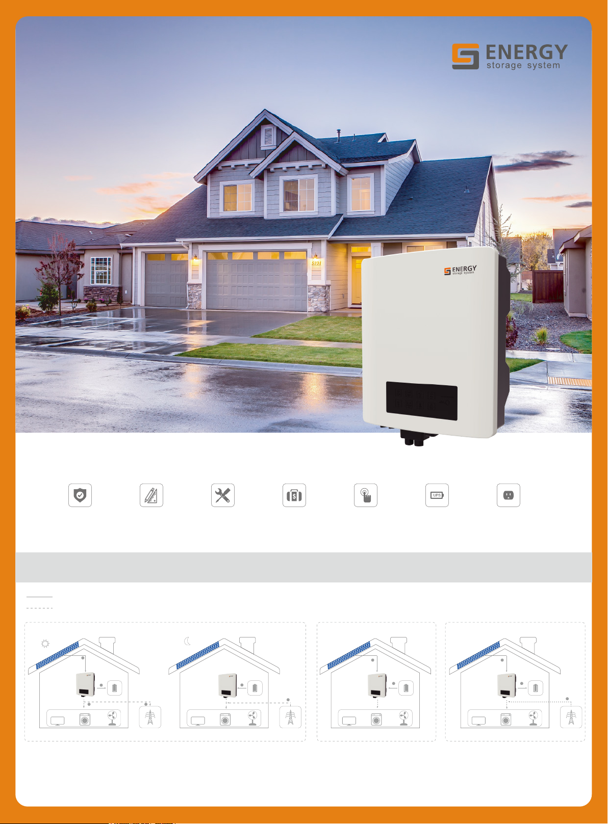
For residential hybrid system
Safety System
DC current
AC current
1
3
2
Diversity
4
Flexible
Installation
1
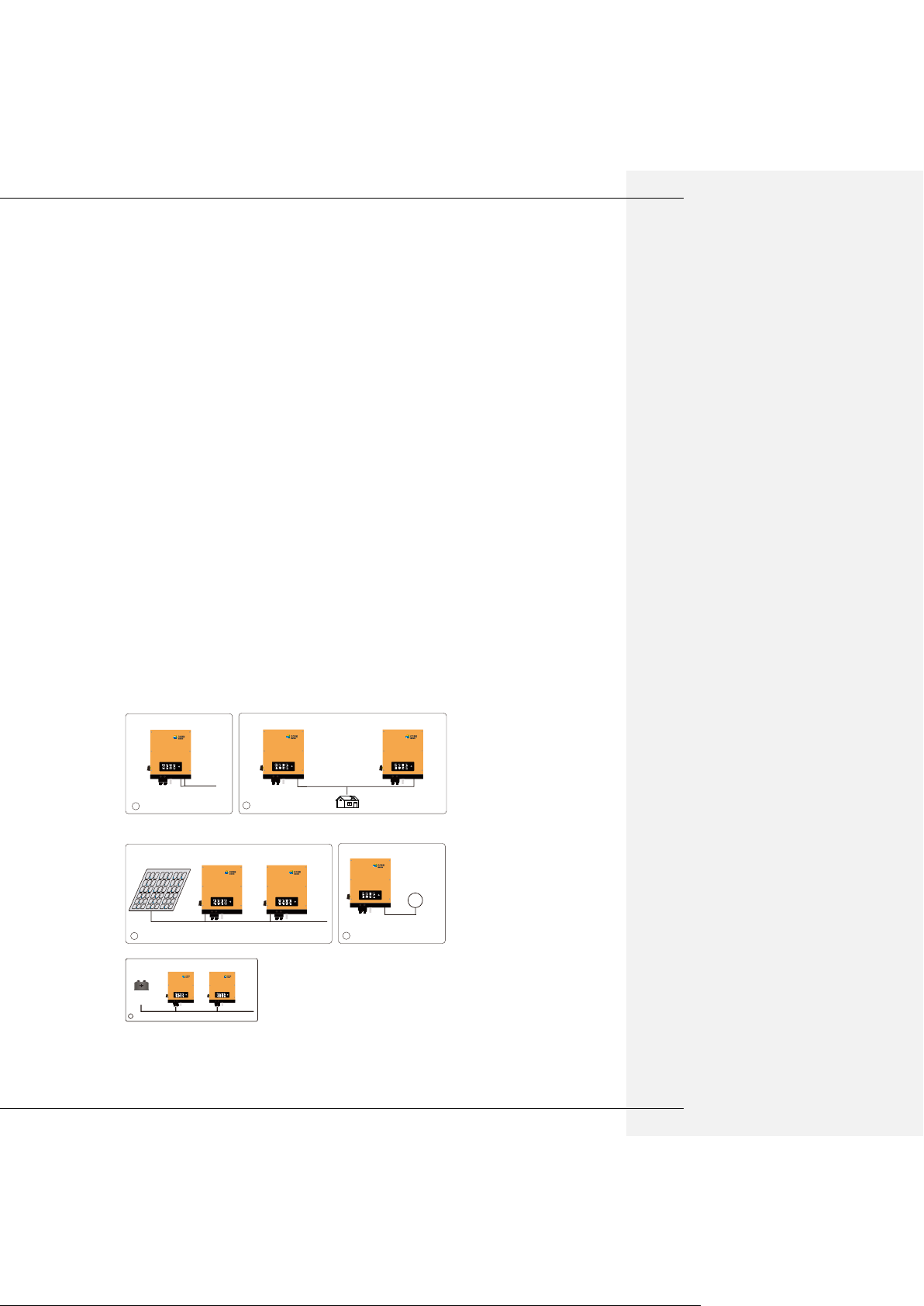
On-grid mode (daytime) On-grid mode (night)
1. PV power generation
2. Supply to load
3. Charge battery
4. Sell to grid
1. Battery supply to load
2. Grid supply to load
Cost-effective Multi-function Plug & PlayUPS Function
Application
1
2
2
Off-grid mode UPS mode
1. PV power generation
2. Battery supply to load
1
2
1. PV power generation
2. Charge battery
3. Grid supply to load
3
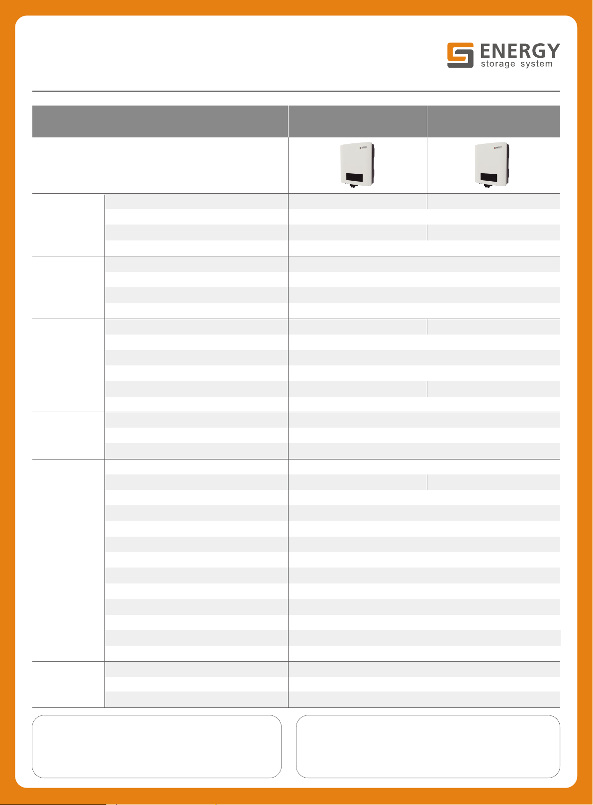
TECHNICAL PARAMETERS
PV
Battery
AC output
Efficiency
General data
Standard
Parameters
Model
Max. input power (W) 3800
Max. input voltage (V)
MPPT voltage range (V)
Nominal input voltage (V)
Voltage range (V) 40 ~ 60
Max. output power (W) 2500
Max. charge / discharge current (A) 50
Communication CAN / RS485
Nominal output power (W) 3000 5000
Voltage range (V) 180 ~ 270
Nominal output frequency (Hz) 50 / 60
Grid type Single-phase
Nominal grid current (A) 16 23
THD < 3%
MPPT efficiency
Max. efficiency
Max. battery efficiency
Weight (kg)
Environmental protection rating IP65
Communication Wifi / RS485 / CAN
Mounting Wall bracket
Ambient temperature (℃) -25 ~ 60 (> 45 derating)
Noise (dB) < 30
Relative humidity 0 ~ 95%
Standard warranty 5 years
Operating altitude (m) 4000 (> 2000 derating)
Cooling Nature cooling
Display LED
Topology Transformerless
Safety IEC62109, IEC62040
EMC
Grid AS4777.2, VDE-AR-N 4105, VDE0126, G99
GS-Hybrid-3K
550
120 ~ 550
360
> 99.9%
> 97.5%
94%
366*476*173Dimensions (W*H*D) (mm)
18 20
EN61000-6-3, EN1000-6-1, EN61000-3-2/11, EN61000-3-3/12
GS-Hybrid-5K
6600
120 ~ 550
Address:
Tashan Industry Zone, Meilin, Ninghai, Ningbo, China
Email:
gsmartenergy@126.com
Note:
08
GS ENERGY STORAGE INVERTER USER MANUAL

08
USER MANUAL ....................................................................................................................................................3
1、introduction: ..........................................................................................................................................3
2、Important Safety Warning ........................................................................................................................3
2.1 Symbols .................................................................................................................................................4
2.2 Safety ....................................................................................................................................................4
3 lnstallation ................................................................................................................................................6
3.1 Packing List ........................................................................................................................................6
3.2 Product Overview ..............................................................................................................................7
3.3 Selecting The Mounting Location ......................................................................................................7
3.4 Mounting ..............................................................................................................................................8
4 Electrical Connection ...................................................................................................................................9
4.1 PV Connection ......................................................................................................................................9
4.2 Battery Connection ............................................................................................................................ 11
4.3 On-grid &Back-up Connection ........................................................................................................ 12
4.4 Communication Connection .............................................................................................................. 13
4.7 Wi-Fi Reset &Reload ........................................................................................................................ 15
4.8 DRED Connection ............................................................................................................................... 15
4.9 Earth Fault Alarm ............................................................................................................................... 16
4.10 System Connection Diagram for Normal mode and UPS mode ...................................................... 16
4.11 System Connection Diagram for Off-grid mode .............................................................................. 16
5 GSMART Manager Illustration .................................................................................................................. 17
6 CEI Auto Test/Power limit function Instruction........................................................................................ 17
7 LED Lights Illustration ............................................................................................................................... 17
8 Work Modes ............................................................................................................................................. 18
9 Trouble shooting ....................................................................................................................................... 19
10. Error Message ........................................................................................................................................ 21
11 Technical Parameters ............................................................................................................................. 22
12 Certificates .............................................................................................................................................. 24
13 Maintenance ........................................................................................................................................... 24

08
USER MANUAL
1、introduction:
The GS Energy storage inverter (hybrid) are bidirectional which apply to PV system with battery to storage energy.
Energy produced by the PV system is used to optimize self-consumption; excess energy is used to charge the
batteries, and then feed into the public grid when the PV energy is adequate.
When PV energy output is insufficient to support connected loads, the system automatically discharge energy from
the batteries if battery capacity is abundant. If the battery energy is insufficient to meet own consumption
requirements, electricity will be drawn from the public grid.
The GS Energy storage inverter is designed for both indoor and outdoor use.
2、Important Safety Warning
Before using the inverter, please read all instructions and cautionary markings on the unit and this manual. Store
the manual where it can be accessed easily.
The GS Energy storage inverter of Gsmart(Ningbo) Energy Storage Technology Co.,Ltd (hereinafter referred to as
Gsmart) strictly conforms to related safety rules in design and test.
Safety regulations relevant to the location shall be followed during installation, operation and maintenance.
Improper operation may have a risk of electric shock or damage to equipment and property.
08
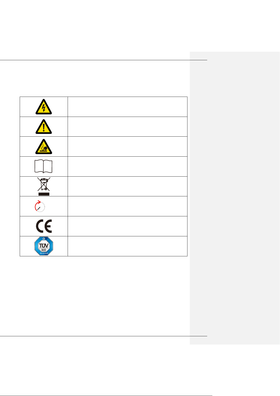
DANGER!
“DANGER” indicates a hazardous situation, if not avoid, it may directly result in
death or serious injury.
Caution!
Failing to observe a warning indicated in this manual may result in injury.
Danger of hot surface!
i
Refer to the operating instructions.
Product should not be disposed as household waste.
5min
Inverter will be touchable or operable after minimum 5 minutes of being
turned off or totally disconnected, in case of any electrical shock or injury.
CE MARK
TUV MARK
2.1 Symbols
2.2 Safety
Installation, maintenance and connection of inverters must be performed by qualified personnel, in
compliance with local electrical standards, wiring rules and the requirements of local power authorities
and/or companies.
To avoid electric shock, DC input and AC output of the inverter must be terminated at least 5 minutes
before performing any installation or maintenance.
The temperature of some parts of the inverter may exceed 60℃ during operation. To avoid being burnt,
do not touch the inverter during operation. Let it cool before touching it.
Ensure children are kept away from inverters.
08
Do not open the front cover of the inverter. Apart from performing work at the wiring terminal (as instructed
LINK BATTERY GRID FAULT
SYSTEM MODEL UPS Wi-Fi
Wi-Fi
Resetting
CCBN
storage specialist
!
√
On Grid
X
1
LINK BATTERY GRID FAULT
SYSTEM MODEL UPS Wi-Fi
Wi-Fi
Resetting
CCBN
storage specialist
!
√
X
LINK BATTERY GRID FAULT
SYSTEM MODEL UPS Wi-Fi
Wi-Fi
Resetting
CCBN
storage specialist
!
√
UPS
LOAD
UPS
2
LINK BATTERY GRID FAULT
SYSTEM MODEL UPS Wi-Fi
Wi-Fi
Resetting
CCBN
storage specialist
!
√
X
LINK BATTERY GRID FAULT
SYSTEM MODEL UPS Wi-Fi
Wi-Fi
Resetting
CCBN
storage specialist
!
√
PV
PV
X
3
LINK BATTERY GRID FAULT
SYSTEM MODEL
UPS
Wi-Fi
Wi-Fi
Resetting
CCBN
storage specialist
!
√
X
X
6
LINK BATTERY GRID FAULT
SYSTEM MODEL UPS Wi-Fi
Wi-Fi
Resetting
CCBN
storage specialist
!
√
LINK BATTERY GRID FAULT
SYSTEM MODEL U PS Wi-Fi
Wi-Fi
Resetting
CCBN
storage specialist
!
√
X
BATTERY
X
……
BATTERY
4
in this manual), touching or changing components without authorization may cause injury to people,
damage to inverters and annulment of the warranty.
Static electricity may damage electronic components. Appropriate method must be adopted to prevent
such damage to the inverter; otherwise the inverter may be damaged and the warranty annulled.
Ensure the output voltage of the proposed PV array is lower than the maximum rated input voltage of the
inverter; otherwise the inverter may be damaged and the warranty annulled.
When exposed to sunlight, the PV array generates dangerous high DC voltage. Please operate according
to our instructions, or it is result in danger to life.
PV modules should have an IEC61730 class A rating.
If the equipment is used in manner not specified by the manufacturer, the protection provided by the may
be impaired.
Completely isolate the inverter before maintaining. Completely isolate the inverter should: Switch off the
DC switch, disconnect the terminal, disconnect the battery terminal, and disconnect the AC terminal.
Prohibit to insert or pull the AC and DC terminal, and the inverter is running.
In Australia, the inverter internal switching does not maintain the neutral integrity, neutral integrity must be
addressed by external connection arrangements like the example proposed in the diagram 4.10.
In Australia, the output of backup side in switchbox should be labeled’ main switch UPS supply’, the output
of normal load side in switchbox should be labeled ’main switch inverter supply’.
Don’t connect GS Energy storage inverter in the following ways:
1) UPS port should not be connected to grid;
2) UPS port should not be connected in parallel;
3) The single PV panel string should not be connected to two or more inverters;
4) On grid or UPS port should not be connect AC generator;
5) One battery(bank) connect with multi inverters.
08
3 lnstallation
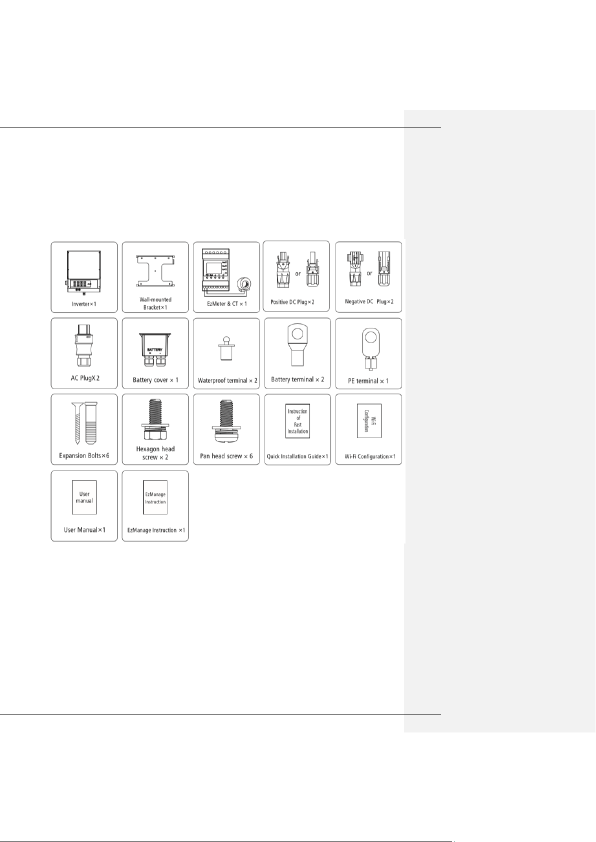
3.1 Packing List
Before installation、please inspect the unit .Be sure that nothing inside the package is damaged. You should
have received the following items inside of package:
08
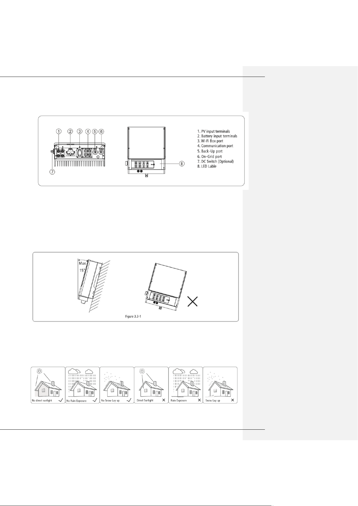
3.2 Product Overview
3.3 Selecting The Mounting Location
Mounting Location should be selected based on the following aspects:
●The installation method and mounting location must be suitable for the inverter’s weight and dimensions.
● Mount on a solid surface.
● Select a well ventilated place sheltered from direct sun radiation.
● Install vertically or tilted backward by max 15°.The device cannot be installed with a sideways tilt. The
connection area must point downwards. Refer to Figure 3.3.1
● In order to achieve optimal performance, the ambient temperature should be lower than 45℃.
● For the convenience of checking the LED lights and possible maintenance activities, please install the
inverter at eye level.
● Inverters should NOT be installed near inflammable and explosive items. Any strong electro-magnetic
equipment should be kept away from installation site.
● product label and warning symbol shall be clear to read after installation.
● Please avoid direct sunlight, rain exposure, snow lay up when install.
● In consideration of heat dissipation and convenient dismantlement, the minimum clearance around the
 Loading...