

Page 1
GSE Model 675
PRECISION SCALE
USER’S GUIDE
Version 3.1
Page 2

Page 3

Model 675
USER’S GUIDE
Version 3.1
Page 4

GSE 675 Precision Scale User’s Guide
Copyright © 2008 GSE. All rights reserved.
Published by:
GSE
1525 Fairlane Circle
Allen Park, MI 48101
USA
Information in this User’s Guide is subject to change without notice due to correction or enhancement. The
information described in this manual is solely the property of GSE. No part of this manual may be
reproduced or transmitted in any form or by any means, electronic or mechanical, including photocopying
and recording and sold for any monetary figure without the express written permission of GSE.
Page 5

Table of Contents
CHAPTER 1: REFERENCE ................................................................................................................ 1
ENCLOSURE ................................................................................................................................................. 1
LOAD CELL ................................................................................................................................................. 2
DISPLAY ...................................................................................................................................................... 2
KEYPAD ...................................................................................................................................................... 3
Keypad Functions ................................................................................................................................... 3
Alpha Entry ............................................................................................................................................. 4
REAR PANEL CONNECTIONS ........................................................................................................................ 5
Scale 2 Connections (Remote Scale) ...................................................................................................... 5
Communication Port Connections .......................................................................................................... 5
Remote key connections .......................................................................................................................... 6
CHAPTER 2: CONFIGURATION ..................................................................................................... 7
F1 – QUICK COUNT ..................................................................................................................................... 8
Quick Count Setup Menu ........................................................................................................................ 8
Setup the Quick Count Mode .................................................................................................................. 8
Advanced Setup Menu .......................................................................................................................... 11
F2 – GSE CUSTOM .................................................................................................................................... 12
APW LOOKUP ........................................................................................................................................... 12
Setup the APW Lookup Mode ............................................................................................................... 12
APW Lookup Setup Menu ..................................................................................................................... 13
Set Modes ............................................................................................................................................. 15
Advanced Setup Menu .......................................................................................................................... 17
F3 – GSE DEFAULT ................................................................................................................................... 18
CHAPTER 3: OPERATION .............................................................................................................. 19
QUICK COUNT ........................................................................................................................................... 19
Sample and Count ................................................................................................................................. 19
Accumulate ........................................................................................................................................... 20
APW LOOKUP ........................................................................................................................................... 21
Sample and Count ................................................................................................................................. 21
Accumulate ........................................................................................................................................... 23
GSE DEFAULT .......................................................................................................................................... 23
CHAPTER 4: CALIBRATION .......................................................................................................... 25
CALIBRATION METHODS ........................................................................................................................... 25
General Notes on Calibration .............................................................................................................. 25
Access Calibration from APW Lookup or Quick Count Mode ............................................................. 26
Access Calibration from the Weigh Mode ............................................................................................ 26
CHAPTER 5: LEGAL FOR TRADE ................................................................................................ 33
NTEP REQUIREMENTS .............................................................................................................................. 33
NTEP CUSTOM SETUP .............................................................................................................................. 34
Accessing the Custom Setup List .......................................................................................................... 34
SEALING AND AUDIT TRAILS..................................................................................................................... 34
Physical Seal ........................................................................................................................................ 34
Audit Trails ........................................................................................................................................... 35
OMIL Requirements ............................................................................................................................. 36
CHAPTER 6: TROUBLESHOOTING ............................................................................................. 37
Operational Errors ............................................................................................................................... 37
Calibration Errors ................................................................................................................................ 38
Communication Errors ......................................................................................................................... 39
i
Page 6

Page 7
y
Chapter 1: REFERENCE
The “Reference” chapter describes the major components of the Model 675 Precision Scale. Keypad functions, load
cell installation, display and connections are described in this chapter.
IMPORTANT!
The Model 675 does not include an on/off switch and, therefore, must be installed near a power outlet socket
that is easil
INFORMATION IMPORTANT!
Prendre note que les model 675 ne sont pas munis d'interrupteurs "Marche / Arrêt". Par conséquent, il devront
être installés près d'une source d'alimentation secteur accessible pour demeurer sous les exigences des normes de
sécurité UL/CSA.
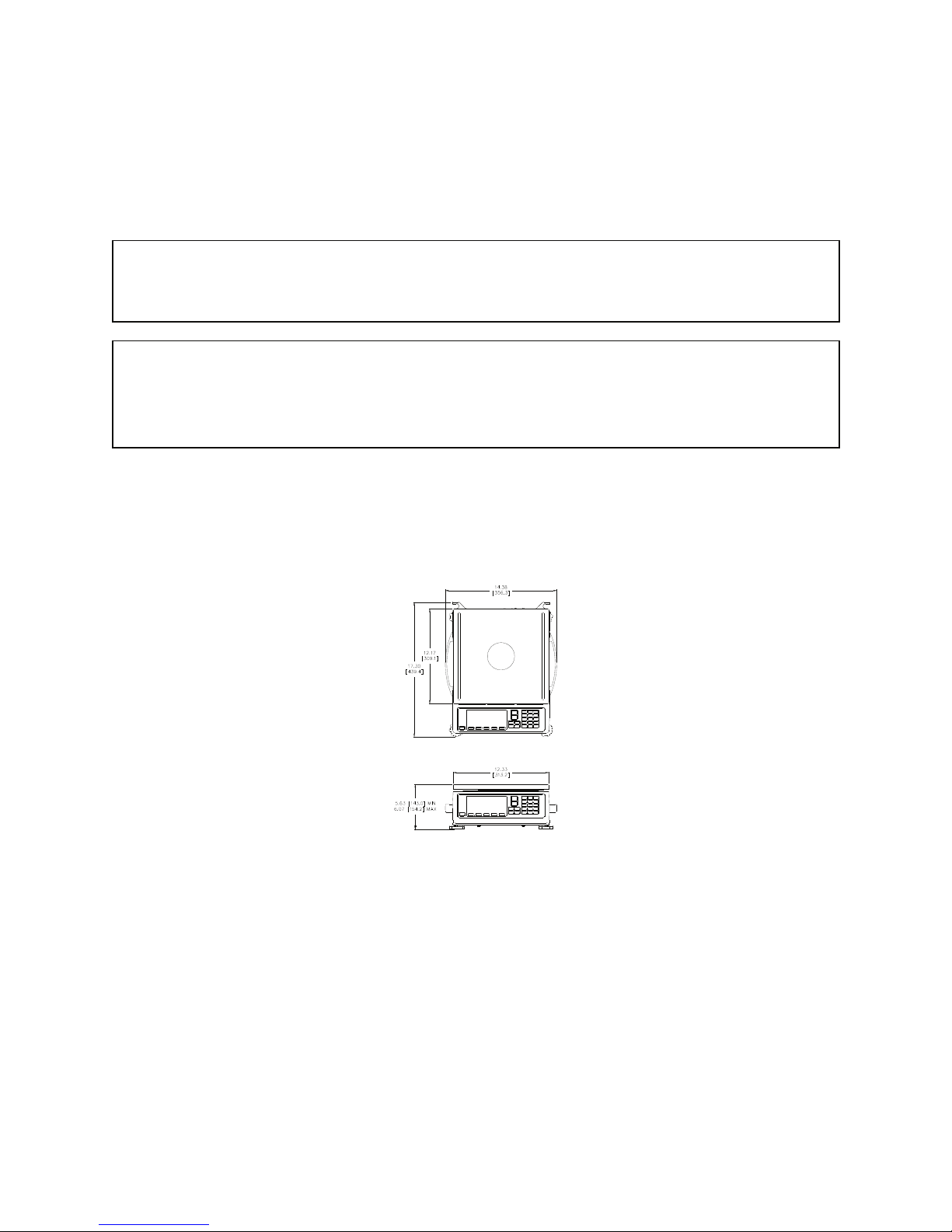
Enclosure
The enclosure is made of die cast aluminum with rib enforcement. This design provides extra strength and
durability. The enclosure is painted with powder coat finish and the counting surface is stainless steel. The enclosure
also includes built in carrying handles and a line cord wrap for ease of portability.
accessible and in keeping with UL/CSA Safety Standards.
Figure 1: Model 675 Outline Drawing
1
Page 8
Model 675 User’s Guide
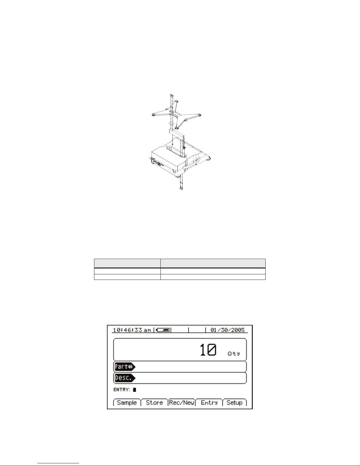
Load Cell
The load cell can be exchanged by removing two M6 1x 20mm (size) bolts from the bottom plate and two M6 1 x
16mm (size) bolts from the top spider assembly.
The load cell cable connects to J15 of the main board. The J15 connector is accessible from the load cell cavity of
the Model 675 enclosure
Figure 2: Model 675 Load Cell Installation
Install the new load cell by placing it in the load cell cavity. Fasten the load cell by installing the bolts on the
bottom plate. Reinstall the spider assembly.
NOTE: When exchanging a load cell with another, the overload stop and corner overloads must be reset. See Table
1 for specifications.
Table 1: Load Cell Overload Stops
Load Cell Stop Set to
Load Cell Center Overload 120 % of full scale
Corner Overloads 60 % of full scale
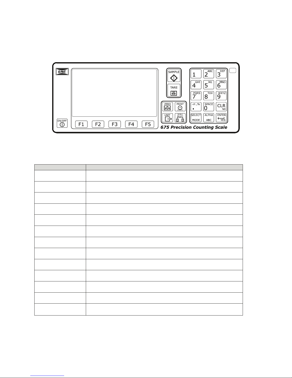
Display
A large 16 line x 40 character graphic LCD provides excellent visibility with user defined help screens and
prompting. The large graphic display features a backlight for use in poorly lit areas.
2
Figure 3: Model 675 Graphic Display
Page 9
Chapter 1
34567
Keypad
The Model 675 comes standard with a durable and versatile polymeric switch plate. The keys are large and easy to
use. The keypad is easily cleaned with a damp cloth or non-abrasive cleaner.
Figure 4: Model 675 Keypad
KEYPAD FUNCTIONS
All of the keys perform different functions. Some keys have more than one function.
Key(s) Description
Act as soft keys which will perform a specific function. Refer to the text on the display
for the function of each soft key.
:
<
9
=
>
K
;
Subtracts the weight of the tare from the displayed weight. Commonly used for
removing the weight of a container.
Performs a gross zero and displays the gross mode.
Performs a sample for an accurate parts counting and calculates an average piece
weight.
Toggles between the available units.
Selects between all enabled scales. The current scale number will be shown on the
display.
Print data from a specified communication port.
Select among modes such as Gross, Net, Tare, Quantity and Average Piece Weight.
Clear the entry buffer or answer “NO” to a question.
Enter data or answer “YES” to a question.
Enable/disable alpha entry mode. Refer to page 4 for setup information.
8
J- H, I
Turn the scale on or off.
Numeric keys used to manually enter a value for tare weight, average piece weight,
sample size etc.
3
Page 10
Multiple Key Functions
Keys Description
Model 675 User’s Guide
= and
J and K
Press at the same time to default database on power up.
Press at the same time to backspace during an alpha entry.
ALPHA ENTRY
The Model 675 provides quick and easy alpha entry. The [ALPHA] key becomes the “Alpha enable/disable” key.
The alpha characters assigned to each numeric key mimic a telephone layout with the addition of the [0/space]
key. This allows additional ASCII characters to be accessed via the decimal point key. The display will show ™
while an alpha entry is in progress and > when the “Alpha” entry mode is disabled. If the ALPHA graphic icon is
enabled, it will also show on the display if an alpha entry is in progress.
Character Entry
When alpha characters and other non-numeric characters are to be entered using the front panel keypad, use the
[ALPHA] key to "build" the entry:
Press the [ALPHA] key to initialize the alpha entry mode. ALPHA will be shown on the display, indicating the
[ALPHA] key is active. Press the [ALPHA] key again to turn alpha entry off.
Keys [2] – [9] have uppercase and lowercase alphabetic characters assigned to them. The [ . ] key scrolls through the
remaining characters. The [0/
simultaneously to backspace one character.
To enter characters, press the corresponding number key on the keypad. The first character in the sequence
(depending on the “Alpha” mode selected) will appear first. Continue pressing the key before the timeout occurs to
scroll through the characters for that key. Refer to Table 2 for character key assignments.
SPACE] is used for inserting a space. Press the [CLR] + [ 0 /SPACE] keys
Table 2: Character Key Assignments
Key
1
[1]
2 A B C a b c
[2]
3 D E F d e f
[3]
4 G H I g h i
[4]
5 J K L j k l
[5]
6 M N O m n o
[6]
7 P Q R S p q r S
[7]
8 T U V t u v
[8]
9 W X Y Z w x y Z
[9]
. - : / # \ ! “ $ % &‘ ( ) * +, ; <=>?@[ ] ^ _ ` { | } ~
[.]
S
[0]
p
0
a
c
e
Character
4
Page 11
Chapter 1
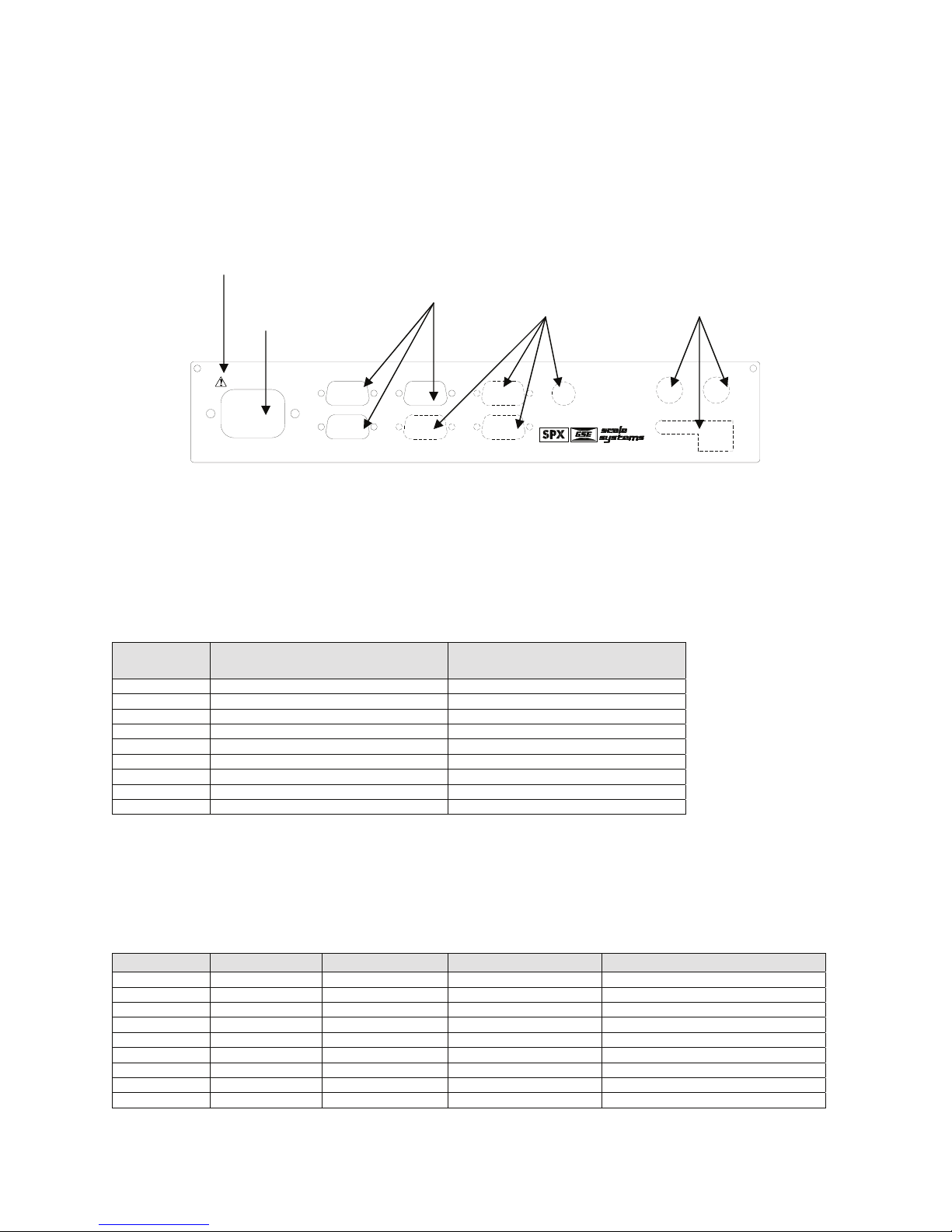
Rear Panel Connections
The Model 675 comes standard with 2 communication ports, which use Male DB-9 connectors. Also a remote base
can be connected to the SCALE 2 Female DB-9 connector. The positions that are shown with dotted lines are
available for options such as scale 3 and 4, Ethernet, communication ports and setpoints. Simply cut along the dotted
line with a knife where the option will be installed. See Chapter 2: Option Installation of the Model 672/675
technical reference manual for complete details on installing options.
NOTE: The means CAUTION. Disconnect power before servicing
Standard
Options Options
Power
90-250VAC
50-60Hz 0.8A
COM 2
SCALE 2COM 1
AUX 1
COM 3
COM 4
675 PRECISION COUNTING SCALE
PS/2
AUX 2
AUX 3
ETHERNET
SCALE 2 CONNECTIONS (REMOTE SCALE)
If a 4-wire load cell cable is being used, jumpers will need to be installed between sense and excitation. The
jumpers will be installed on the DB9 connector being installed on the load cell cable. The intention of pins 8 and 9
on the DB9 are to connect the sense and excitation in 4 wire load cell applications without having to solder two
wires in one hole. Refer to Table 3 for scale 2 pin out connections.
Table 3: Scale 2 DB 9 Connector Pin Out
DB9 pin
designation
1 + Signal 4 or 6 wire
2 - Signal 4 or 6 wire
3 + Sense 4 wire (connect a wire jumper to pin 8)
4 - Sense 4 wire (connect a wire jumper to pin 9)
5 - Excitation 4 or 6 wire
6 + Excitation 4 or 6 wire
7 Chassis Ground 4 or 6 wire
8 + Excitation 4 wire (connect a wire jumper to pin 3)
9 - Excitation 4 wire (connect a wire jumper to pin 4)
Connection Load Cell Cable
COMMUNICATION PORT CONNECTIONS
Comm port 1 and 2 are standard on the Model 675. Comm port 3 and Comm port 4 are optional. Refer to Table 4
for communication port pin outs.
Table 4: Communication Ports 1 - 4 Pin Out
DB9 pin Comm 1 Comm 2 Comm 3 (optional) Comm 4 (optional)
1 No connection TTL No connection No connection
2 RXD RXD RXD RXD
3 TXD TXD TXD TXD
4 + 5 V + 5V + 5V + 5V
5 ISO Ground Ground Ground Ground
6 Ground Ground Ground Ground
7 RTS RTS No connection No connection
8 CTS CTS CTS No connection
9 Remote Key 1 Remote Key 2 No connection No connection
5
Page 12

Model 675 User’s Guide
Comm 2 Jumper (J24)
These jumpers are only on board rev E and higher (420992-40682 rev E). This allows for a choice in scanner power
supply pins and to minimize modifications to a cable or connector.
Comm port 2 has a pin on the DB 9 connector which provides + 5 volts to supply power to a scanner. The jumpers
will reroute the power (+ 5 volt) on comm port 2 to either pin 9 or pin 4 depending on jumper orientation.
Table 5: Power Jumpers
J24 Position Orientation
Pin# Parallel to rear panel Perpendicular to rear panel
4 Remote Key + 5 Volt
9 + 5 Volt Remote Key
Jumper Configuration
The power (+ 5 volt) and remote key pins are switched. Refer to Figure 5 for the jumper location on the main board.
Factory Default Previous Configuration
Figure 5: J24 Location on Main Board
REMOTE KEY CONNECTIONS
The Model 675 allows for two remote key inputs. The inputs can be used for invoking a macro to perform tasks
such as zero, print, tare etc. See the chart below for comm port and pin assignment. Refer to the Model 672/675
technical reference manual for function key assignment.
Table 6: Remote Key
Remote Key Port Pins Macro
1 Comm 1 6 and 9 6
2 Comm 2 6 and 9 7
6
Page 13
Chapter 2: CONFIGURATION
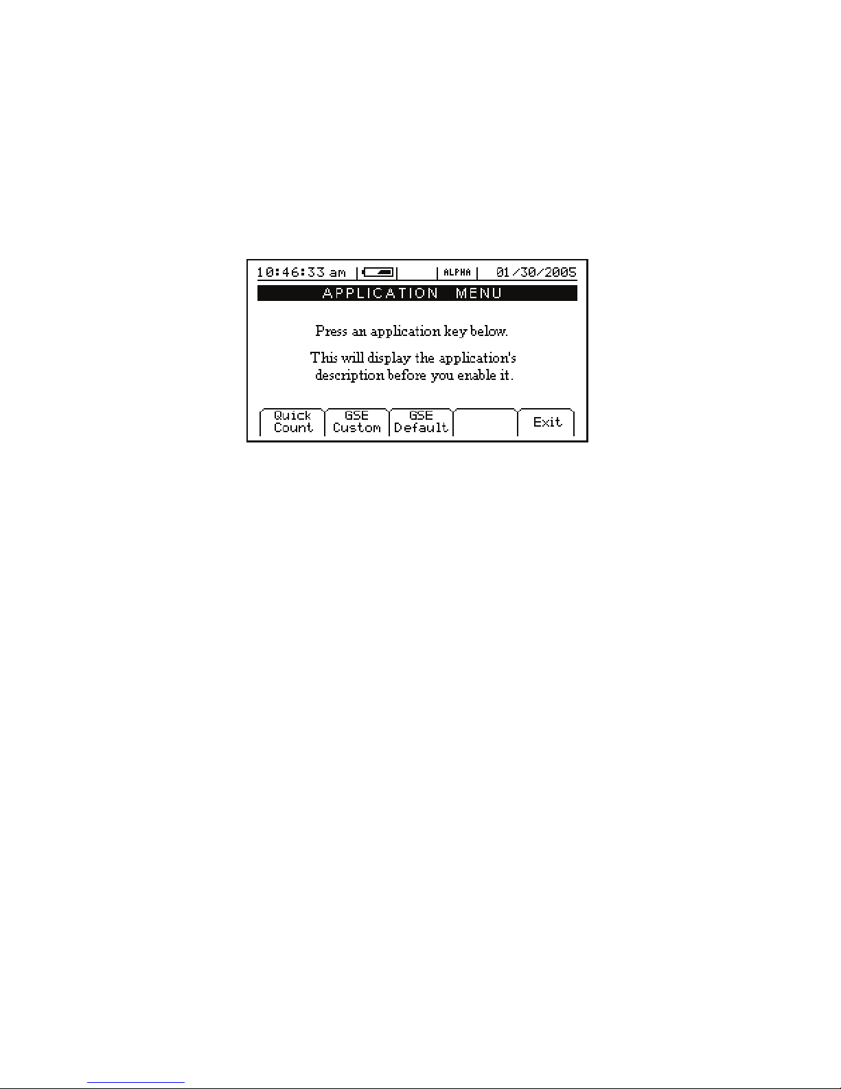
The GSE 675 Precision Counting Scale comes from the factory with the Application Menu enabled. This
is where you will choose the preferred method of parts counting or weighing. See the explanations of each
method below. After each counting method are the instructions for setting up that method.
Refer to Chapter 4 for operating instructions of each method.
F1 F2 F3 F4 F5
Figure 6: Model 675 Power Up Screen
7
Page 14
Model 675 User’s Guide
F1 – Quick Count
The QUICK COUNT mode is designed for performing a quick sample and count. The soft keys are used in
secession from left to right to increase speed and ease of parts counting. Basic functionality is offered to
simplify operation. Below are the available soft keys and an explanation of their purpose in the QUICK
COUNT mode.
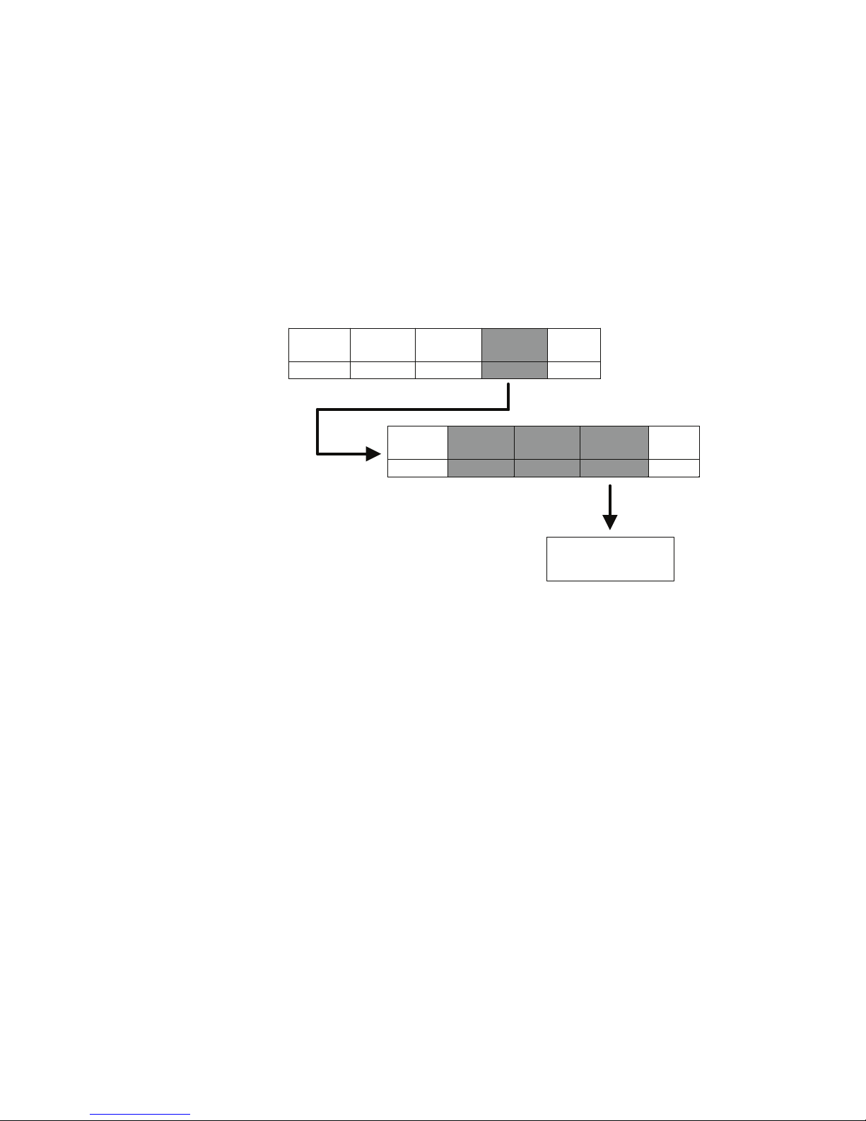
QUICK COUNT SETUP MENU
Use the [F4] Setup menus key from the “Quick Count” screen to gain access to different menus. Menu
items shaded in gray are multiple level.
Change
Sample
F1 F2 F3 F4 F5
Clear
Totals
Key-In
APW
Cal
F1 F2 F3 F4 F5
Menus
Display
Style
Setup
Print
Formats
Exit
Advance
Setup
See Advanced Menu
Section for complete
details
Exit
SETUP THE QUICK COUNT MODE
1. Press [F1] from the “Application Menu”. The display will come up with an explanation of the “Quick
Count” menu.
2. At this time you can choose the “Quick Count” mode by pressing [ENTER] (YES) or return to the
“Application Menu” by pressing [F5] (Exit) or [CLR] (NO).
The “Quick Count” file will load automatically and return to the “Quick Count” mode.
8
Page 15

Chapter 2
Setup
This menu was designed for accessing the items that will need to be changed the most often. Below is an
explanation of the choices in the menu. Follow the instructions on the display for each key.
UNCTION
F
KEY
3
4
5
6
P
ARAMETER DESCRIPTION
CHANGE
SAMPLE
CLEAR TOTALS
KEY-IN APW
SETUP MENUS
Change the default
sample size
Clears the accumulation
registers
Key in an average piece
weight for sample
Continues on to the
Setup Menus
EFAULT
D
SETTING
10
Not applicable Press [Enter] to clear totals or [Clr] to escape
0
Not applicable Press [F4] to continue
Setup Menus
This is the next level of menus, which offer more advanced setup.
UNCTION
F
KEY
3
4
5
6
P
ARAMETER DESCRIPTION
CAL
DISPLAY STYLE
PRINT MENU
ADVANCE SETUP
Calibration any of the
enabled scales
Chose how the display
will appear
Choose what
information to print out
Continues on to the
Advanced Setup Menu
D
EFAULT
SETTING
Not applicable
Style 2
Not applicable Continues on to the Print Menu selections
Not applicable See page 11
K
EYPRESS
Key in new sample size and press [Enter] to
Key in new average piece weight and press
Key in access code and press Enter or press [F5]
Press either [F1] – [F3] to chose the desired
accept or [F5] to escape
[Enter] or [F5] to escape
K
EYPRESS
to escape
display style or [F5] to escape
Cal (Calibration)
Refer to Chapter 4 for complete instructions on calibrating the Model 675.
Display Style
Choose one of the display types and press [F5] (EXIT) to save the change and return to the main menu.
STYLE 1
This is the classic GSE 2x5 display. The weight or quantity will be displayed in larger font while the
prompts will be to the right of the weight display.
STYLE 2
This style incorporates the classic GSE 2x5 display along with two smaller displays, which will show other
parameters. Press the [SELECT] key from the QUICK COUNT to toggle through the different parameter
choices.
9
Page 16

Model 675 User’s Guide
Preset Print Formats
The preset print formats are viewable on the LCD display. Use the [F3] left arrow and [F4] right arrow
keys to view all transmit styles. Choose the desired format by viewing it on the screen. Press the [F5]
(EXIT) key to save the format and return to the main menu.
Print #1 Print #2
Quantity: 30 Quantity: 30
APW: 0.1234 APW: 0.1234
Tare: 1.515 lb Tare: 1.515 lb
10:10:00 am 01/30/2005
Print #3 Print #4
Quantity: 30 Part#: 123
Tare: 1.515 lb Quantity 55
APW 0.4481
Scale #: 2 Tare 1.623 lb
Print #5 Print #6
10.025 lb Gross Quantity: 55
2.500 lb Tare QTY Total: 510
7.525 lb Net Total Accums: 10
Print #7
Part#:Quantity 55
APW 0.4481
Tare 1.623 lb
10:10:00 am 01/30/2005
10
Page 17

Chapter 2
ADVANCED SETUP MENU
The advanced menu will allow access to the time/date, setup mode and application files. Use the arrow
keys to navigate to the desired tab. This is common on the preprogrammed methods of counting such as
QUICK COUNT and APW.
Time/Date
1. From the time/date tab, press [ENTER] to access the configuration screen. The time can be changed
with the [F1] key. The date can be changed with the [F2] key.
2. Key in the time or date by following the format on the display and press [ENTER] to accept the entry.
3. Press [F5] (EXIT) to return to the main menu.
Setup (Setup Mode Access)
This tab allows access to the setup mode to make changes to parameters such as full scale, count accuracy
and baud rate etc. Please refer to the Model 672/675 technical reference manual for details on more
advanced setups and configurations.
Access the setup mode:
1. From the Setup tab press [ENTER].
2. Key in the access code and press [ENTER].
Apps (Application Menu)
Access the Application Menu to switch to another operating mode or the factory default mode.
1. From the Apps tab press [ENTER].
2. Key in the access code and press [ENTER]. The Apps Menu will automatically load.
NOTE: Press [F5] at any time to abort loading the Apps Menu.
Scanner
This tab was specifically designed to show the string received from a scanner. Scan a label and the raw
scanner data will be shown on the display. This is very useful for troubleshooting an input interpreter.
11
Page 18

Model 675 User’s Guide
F2 – GSE Custom
Presently APW LOOKUP is the only application offered under GSE Custom.
The APW LOOKUP offers the flexibility of storing and recalling part numbers. The average piece weight
and part description will be stored and recalled with the part number.
APW Lookup
The APW LOOKUP offers the flexibility of storing and recalling part numbers. The average piece weight
and part description will be stored and recalled with the part number.
F1 F2 F3 F4 F5
Figure 7: Model 675 APW Lookup Screen
SETUP THE APW LOOKUP MODE
1. Press the [F2] (GSE Custom) from the “Application Menu”.
2. Press [F1] (APW Lookup). The display will come up with an explanation of the “Application Menu”
menu.
3. At this time you can choose the “Application Menu” mode by pressing [ENTER] (YES) or return to
the menu choices by pressing [F5] (Exit) or [CLR] (NO).
4. The “Application Menu” file will load and will return to the “Application Menu” mode.
12
Page 19

Chapter 2
APW LOOKUP SETUP MENU
Use the [F5] Setup key from the “Application Menu” screen to gain access to different menus.
Change
Sample
Delete
Part#
F1 F2 F3 F4 F5
Style
1
Style
2
Style
3
Set
Modes
F1 F2 F3 F4 F5
Next Enable Disable Exit
F1 F2 F3 F4 F5
Print
Part#s
D-Load
Part#s
F1 F2 F3 F4 F5
Cal
Key-In
APW
Display
Setup
Menus
Style
Print
Menu
Exit
Advance
Setup
F1 F2 F3 F4 F5
Exit
See Advanced Menu
Section for complete
details
Print
Exit
Formats
Exit
Comm
1
Comm
2
Exit
F1 F2 F3 F4 F5
Comm
1
Comm
2
Exit
F1 F2 F3 F4 F5
13
Page 20

Model 675 User’s Guide
Setup
This menu was designed for accessing the items that will need to be changed most often. Below is an
explanation of the choices in the menu. Follow the instructions on the display for each key. The cell
shaded in gray has a multiple level menu.
UNCTION
F
3
4
5
6
KEY
P
ARAMETER DESCRIPTION
CHANGE
SAMPLE
DELETE PART #
KEY-IN APW
SETUP MENUS
The YES key is [ENTER] the NO key is [CLR].
Change the default
sample size
Delete specified part
number
Key in an average piece
weight for sample
Continues on to the
Setup Menus
D
EFAULT
S
ETTING
10
Will not show
until a part number
is established
0
Not applicable Press [F4] to continue
Key in new sample size and press Enter to accept
Key in part # and press [F3]. Press [F5] to enter
the setup. Press [F2] to delete part #.
Key in new average piece weight and press
K
EYPRESS
or [F5] to escape
[Enter] or [F5] to escape
Setup Menus
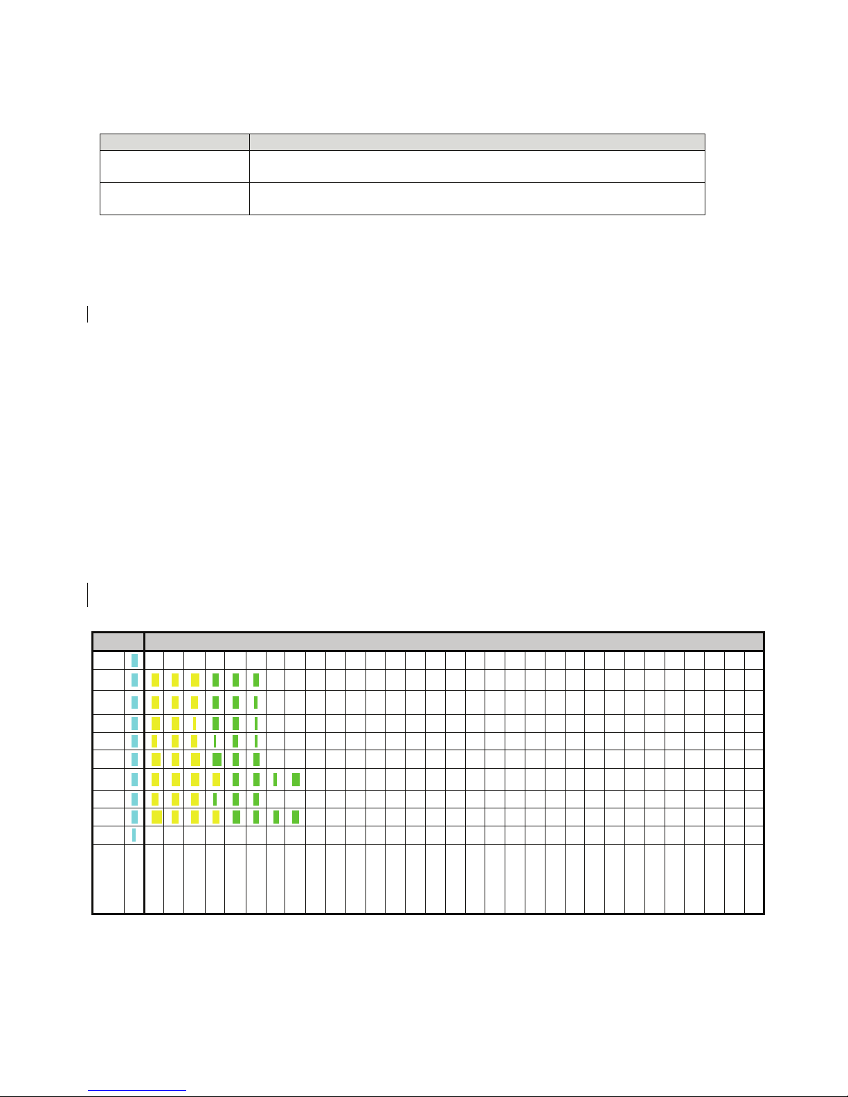
This is the next level of menus, which offer more advanced setup. The cells shaded in gray have a multiple
level menu.
UNCTION
F
KEY
3
4
5
6
P
ARAMETER DESCRIPTION
CAL
DISPLAY STYLE
PRINT MENU
ADVANCE SETUP
Calibration any of the
enabled scales
Chose how the display
will appear
Choose what
information to print out
Continues on to the
Advanced Setup Menu
EFAULT
D
SETTING
Not applicable
Style 2
Not applicable Continues on to the Print Menu selections
Not applicable See page 17
Key in access code and press [Enter] or press
Press either [F1] – [F3] to chose the desired
K
EYPRESS
[F5] to escape
display style or [F5] to escape
Cal (Calibration)
Refer to Chapter 5 for complete instructions on calibrating the Model 675.
Display Style
Different display styles are offered to help customize the Model 675 parts counter to fit your needs. Choose
one of the display types and press [F5] (EXIT) to save the change and return to the main menu. By using
the [SELECT] key several modes can be viewed from the “Application Menu” screen. See the section on
Set Modes on page 15.
STYLE 1
The top display will show the weight or quantity in larger font while the second display will show the part
number in medium font. Press the [SELECT] key from the “Application Menu” screen to toggle through
the different parameter choices.
14
Page 21

Chapter 2
Large display Medium display
Gross Part #
Net Part #
Tare Part #
APW (average piece weight) Part #
% Accuracy Part #
Last Sample Part #
Quantity Total Part #
# Accumulations Part #
Quantity Part #
STYLE 2
This style incorporates the classic GSE 2x5 display and a second display, which will show three other
parameters. Press the [SELECT] key from the “Application Menu” screen to toggle through the different
parameter choices.
Large Display Small Display Small Display Small display
Quantity Part# APW Description
Gross Part# APW Description
Net Part# APW Description
Tare Part# APW Description
STYLE 3
This style incorporates the classic GSE 2x5 display along with three smaller displays which will show four
other parameters. Press the [SELECT] key from the “Application Menu” screen to toggle through the
different parameter choices.
Large Display Small Display Small Display Small display
Quantity Gross Net Tare
Quantity Part# Piece Weight Tare
Quantity Net Tare Gross Total
Gross Part# % Accuracy Piece Weight
Quantity Part# % Accuracy APW x 100
Quantity Piece Weight % Accuracy Tare
SET MODES
After choosing a display style there are several modes of operation (such as Gross and Quantity) to choose
from. These modes are accessible by using the [SELECT] key while viewing the “Application Menu”
mode. The ability exists to enable or disable each choice.
1. Press [F4] to access the SET MODES menu.
2. Use the [F1] Next Mode key to toggle through the available modes.
3. Use the [F2] Enable Mode key to enable the mode.
4. Use the [F3] Disable Mode key to disable the mode.
5. Press [F5] to exit back into the APW LOOKUP screen.
15
Page 22

Print Menu
Model 675 User’s Guide
PARAMETER DESCRIPTION
PRINT PART#S
D-LOAD PART#S
PRINT FORMATS
Print stored part numbers to printer or
computer
Download part number, description,
average piece weight and tare weight
in comma delimited format
Choose what information to print out Print Style 1
DEFAULT
SETTING
Not applicable
Not applicable Print data to comm. 1or 2. Use [F1] or [F2]
Print data to comm. 1, 2 or display. Use [F1] or
Use [F3] and [F4] to view print format choices.
KEYPRESSES
[F2]
Press [F5] to save the format
PRESET PRINT FORMATS
The preset print formats are viewable on the LCD display. Use the [F3] left arrow and [F4] right arrow
keys to view all transmit styles. Chose the desired format by viewing it on the screen. Press the [F5]
(EXIT) key to save the format and return to the main menu.
Print #1
1/31/05
Part# 456
Description Drywall Screws
6.15 lb Gross
1.15 lb Tare
5.00 lb
<Barcode here>
Qty 100
Net
0..054139 lb
APW
Print #2
PART #:
<Barcode here>
456
APW :
<Barcode here>
A0.054139
TARE :
<Barcode here>
T1.15
Print #3
456
P/N:
<Barcode here>
0.054139
APW:
<Barcode here>
1.15 lb
<Barcode here>
TARE:
8888
LOT:
<Barcode here>
5555
<Barcode here>
BIN:
16
Page 23

Chapter 2
Print #4
1/31/05
PN:
Lot #
456
8888
APW:
0.054139 lb
TARE:
1.15 lb
<Barcode here>
<Barcode here>
<Barcode here>
<Barcode here>
QTY: 100
Print #5 - 9
Reserved for future use.
Custom Print
CREATE A CUSTOM TRANSMIT FORMAT!
→ SEE THE TECH MANUAL FOR DETAILS
→ CREATE AND LOAD AS TRANSMIT #130
ADVANCED SETUP MENU
The advanced menu will allow access to the time/date, setup mode and application files. Use the arrow
keys to navigate to the desired tab. This is common on the preprogrammed methods of counting such as
QUICK COUNT and APW.
17
Page 24

Model 675 User’s Guide
Time/Date
4. From the time/date tab, press [ENTER] to access the configuration screen. The time can be changed
with the [F1] key. The date can be changed with the [F2] key.
5. Key in the time or date by following the format on the display and press [ENTER] to accept the entry.
6. Press [F5] (EXIT) to return to the main menu.
Setup (Setup Mode Access)
This tab allows access to the setup mode to make changes to parameters such as full scale, count accuracy
and baud rate etc. Please refer to the Model 672/675 technical reference manual for details on more
advanced setups and configurations.
Access the setup mode:
3. From the Setup tab press [ENTER].
4. Key in the access code and press [ENTER].
Apps (Application Menu)
Access the Application Menu to switch to another operating mode or the factory default mode.
3. From the Apps tab press [ENTER].
4. Key in the access code and press [ENTER]. The Apps Menu will automatically load.
NOTE: Press [F5] at any time to abort loading the Apps Menu.
Scanner
This tab was specifically designed to show the string received from a scanner. Scan a label and the raw
scanner data will be shown on the display. This is very useful for troubleshooting an input interpreter.
F3 – GSE Default
If the preprogrammed applications are not going to be used, than the Model 675 should be factory
defaulted. This mode will reset the Model 675 to GSE factory default status. The preset applications will be
lost but can be reestablished at parameter 65002 (refer to the Model 672/675 technical reference manual for
details).
The Model 675 can still be used as a parts counter after it is factory defaulted. Refer to page 23 for more
details on simple counting.
SETUP THE GSE DEFAULT MODE
1. Press [F3] from the “Application Menu” prompt. The display will give an explanation of the GSE
DEFAULT.
2. Press [ENTER] (YES) to accept the choice of GSE DEFAULT and continue or press [CLR] to cancel
the default and return to the “Application Menu”.
3. If you chose to continue with the default in step 2 the display will ask ARE YOU SURE? Either press
[ENTER] (YES) to default the unit or press [CLR] to cancel the default and return to the “Application
Menu”.
18
Page 25

Chapter 3: OPERATION
This chapter will give detailed operation instructions on how to use each preprogrammed mode.
The Model 675 is designed to operate from the 5 soft keys or the dedicated keys of the keypad. The
advantage of using the soft keys is they are placed in succession for easy operation.
Bypass the GSE splash screen on power up by pressing the K key when the splash
screen appears.
Quick Count
This section provides explanation on how to use the Quick Count Method. Refer to page 8 for instructions
on setting the Model 675 up for Quick Count.
3
4
5
6
7
Sample
Count
Accum
Print
Setup
SAMPLE AND COUNT
Press [F1] to sample pieces. See page 19 for more details on counting and
sampling. The default sample size is used unless a new sample size is keyed in.
Press [F2] to access the quantity mode. This key is primarily used for continuing
to count pieces using the current average piece weight.
Accumulate - Maintains a total of quantity accumulations. Press [F3] to add the
current quantity to the total.
Press [F4] to print a ticket or send a transmit to a computer.
Access setup menus, see page 8 for further details.
Follow the steps below obtain an average piece weight (Sample) and count parts (Count).
Auto Tare Method
Sampling Pieces:
1. If a container is used:
Place an empty container on scale and press the [F1] Sample or [SAMPLE] key. The scale will
automatically tare the container.
- or -
2. If a container is not used:
Press the [F1] Sample or [SAMPLE] key without the sample pieces on the scale. The scale will
perform a tare to establish a net zero reference.
19
Page 26

Model 675 User’s Guide
3. Add the sample pieces and press the [F1] Accept key to accept the sample.
4. Continue to add pieces to count.
Without Auto Tare
1. If the sample size is known and a container is used:
a. Place an empty container on the scale and press [TARE] key.
b. Place the sample in the container.
c. Key in the sample size and then press the [F1] Sample or [SAMPLE] key. The scale will accept
the current weights as a sample and will display the quantity.
2. If the sample size is known and no container is used:
a. Place the sample on the scale.
b. Key in the sample size and then press the [F1] Sample or [SAMPLE] key. The scale will accept
the current weights as a sample and will display the quantity.
Example: [5] [0] [SAMPLE]
Use the [SELECT] key to check other modes such as the Tare weight and Average Piece
Weight. The [F2] (Count) can be pressed to return to the count mode at any time.
ACCUMULATE
Press [F3] to accumulate the current quantity to the total quantity. Press [F4] to print to a computer, printer
or another peripheral device.
After accumulating, the weight must return to zero before another accumulation will be added. The display
will show CLEAR WGHT! if the weight is not within the zero threshold. Remove weight and try again.
This feature is necessary to avoid double accumulations.
20
Page 27

Chapter 3
APW Lookup
Follow the steps below to perform a sample and count parts. Also the ability exists to store part numbers,
lot numbers, bin numbers and average piece weight (APW).
3
4
5
6
7
Sample
Store
Rec/New
Entry
Setup
Uses default sample size and prompts user to add that many pieces.
Store a part number with average piece weight and description.
Add a new part number or recall a part number from the database.
This only appears when a part number is entered. Scan in or key in the part
number and press [F3]. Press [F4] to access the Description, Lot #, Bin # and
APW fields.
Access setup menus, see page 14 for further details.
SAMPLE AND COUNT
Follow the steps below obtain an average piece weight (Sample) and count parts (Count).
Auto Tare Method
Sampling Pieces:
1. If a container is used:
Place container on scale and press the [F1] Sample or [SAMPLE] key. The scale will
automatically tare the container.
- or -
2. If a container is not used:
Press the [F1] Sample or [SAMPLE] key without the sample pieces on the scale. The scale will
tare to establish a net zero reference.
or
3. Add the sample pieces and press the [F1] Accept key to accept the sample.
4. Continue to add pieces to count.
21
Page 28

Model 675 User’s Guide
Without Auto Tare
1. If the sample size is known and a container is used:
a. Place an empty container on the scale and press [TARE] key.
b. Place the sample in the container.
c. Key in the sample size and then press the [F1] Sample or [SAMPLE] key. The scale will accept
the current weights as a sample and will display the quantity.
-or-
2. If the sample size is known and no container is used:
a. Place the sample on the scale.
b. Key in the sample size and then press the [F1] Sample or [SAMPLE] key. The scale will accept
the current weights as a sample and will display the quantity.
Example: [5] [0] [SAMPLE]
Store a Part Number
Part numbers can be stored in a database and can be recalled later with necessary data such as the average
piece weight and description. Make sure you enter a part number before entering a Bin #, Lot # or APW.
1. Scan in a part number or key in the part number and press the [F3] (Rec/New) key. The other data
fields will be cleared.
2. If you want to add a part description, Bin #, Lot # and/or an APW either scan it in or press [F4]
(Entry).
If the field was scanned it will automatically be populated. Go to step 4.
If none of these fields are desired, go to step 4.
3. Press the key associated with the desired field (see page 4 for details on alpha entry). Key in the text
and press [ENTER] .
4. Press [F2] to store the part number, APW, Lot #, Bin # and description.
Update a Part Number
It is possible to update the data that is stored with a part number.
1. While viewing the part number and data press [F2] (Store). The data will be updated in the database.
Recall a Part Number
A part number that was stored previously can be recalled to count parts without having to sample the part.
1. Key in the part number to recall and press [F3] (Rec/New). If any other fields were entered they will
appear as well.
2. Place pieces on the platform to count.
22
Page 29

Chapter 3
Delete a Part Number
Any part number that is stored may be deleted.
1. Recall the part number to be deleted by keying in the part number and pressing [F3] (Rec/New). The
part number does not have to be recalled if it is already being viewed.
2. Press [F5] (Setup).
3. Press [F2] (Delete Part#). You will be prompted with the part number to be deleted and the choice of
deleting the part number or aborting the process. This key will not appear if a part number has not been
recalled.
4. Press [CLR] to cancel and return to the APW LOOKUP screen or [ENTER] to continue deleting the
part number.
ACCUMULATE
Press [F3] to accumulate the current quantity to the total quantity. Press [F4] to print to a computer, printer
or another peripheral device.
After accumulating, the weight must return to zero before another accumulation will be added. The display
will show CLEAR WGHT! if the weight is not within the zero threshold. Remove weight and try again.
This feature is necessary to avoid double accumulations.
GSE Default
Simple Keypad Sample
AUTO TARE METHOD
1. Sampling Pieces:
(a) If a container is used - Place container on scale and press the
will automatically tare the container.
(b) If a container is not used - Press the
The scale will tare to establish a net zero reference.
2. Add the sample pieces and press the
9 key. The scale
- or -
9 key without the sample pieces on the scale.
9 key to accept the sample.
3. Continue to add pieces to count.
23
Page 30

WITHOUT AUTO TARE
1) If the sample size is known and a container is used:
Model 675 User’s Guide
a. Place an empty container on the scale and press
b. Place the sample in the container.
c. Key in the sample size and then press the
weights as a sample and will display the quantity.
-or-
1) If the sample size is known and no container is used:
a. Place the sample on the scale.
b. Key in the sample size and then press the
weights as a sample and will display the quantity.
: key.
9 key. The scale will accept the current
9 key. The scale will accept the current
Example: D J 9
24
Page 31

Chapter 4: CALIBRATION
The calibration mode is accessible through the configuration menu or from the weigh mode.
Calibration Methods
There are six methods of calibration. Press > to select a calibration method. Press to begin the
calibration method selected. Refer to the appropriate section for calibration instructions.
• New Zero - Establishes a new zero (no load) and span (test load) calibration reference.
• Last Zero - Performs a span re-calibration without removing the test load. (This selection is not
available with linearization enabled.)
• Temp Zero - Performs a calibration without removing the current gross weight. The zero
reference determined during the last calibration is maintained. (This selection is not available with
linearization enabled.)
• Only Zero - Establishes a new zero reference without affecting span.
• Cal Reset - Adjusts the zero and gain factors of the A/D amplifier to default values for
maximum sensitivity.
• Known LCOut - Calibrates without the use of test weights. The mV/V value and full scale
capacity of each load cell must be known.
GENERAL NOTES ON CALIBRATION
• Pressing K at any point in the calibration routine moves back one step.
• Pressing
• A calibration weight can be applied before or after entering the calibration weight value. The
display prompts you to Keyin CalWt (key in calibration weight) or Add CalWT (add calibration
weight) at the appropriate time.
• The digital filter is automatically set to 4 seconds during calibration.
• A motion delay is enforced during zero and span calibration.
• New calibration values are not permanently saved until the calibration mode is exited and
changes are saved by pressing
calibration, the previously saved calibration values will be in effect when power is restored.
K at the New Zero? prompt exits calibration mode.
at the ENTER=SAVE prompt. If power is lost during
• If replacing one scale with another, it is possible to set the total gain value (P61108) of the new
scale with that of the original. This will optimize the coarse and fine gain values, greatly
increasing the likelihood of a successful calibration on the first attempt.
25
Page 32

Model 675 User’s Guide
ACCESS CALIBRATION FROM APW LOOKUP OR QUICK COUNT
MODE
1. From the main menu press the 7 (Setup) key.
2. Press
3. Press
4. Enter the access code and press
6 (Setup Menus) key.
3 (CAL) key.
ACCESS CALIBRATION FROM THE WEIGH MODE
1. Key in ?JJ >
2. Enter access code
3. Select a calibration method from the list below.
DC@B?
New Zero
The most common calibration procedure, New Zero establishes a new zero (no load) and span (test load)
calibration reference. Use this method for first-time calibration and complete re-calibration.
TO PERFORM A NEW ZERO CALIBRATION:
1. Remove all weight from the scale.
2. Enter calibration as described on page 26.
3. Select the New Zero calibration method as described in Calibration Methods on page 25.
4. Press
5. After establishing the zero reference, the default calibration units are displayed momentarily
6. Apply the calibration weight, key in the calibration weight value in terms of the default calibration
at the New Zero? prompt to establish the new zero reference.
followed by the Keyin CalWt prompt.
units and press
If the calibration weight value was entered before
Add CalWT. Add the calibration weight and press
to establish span.
the weight was applied, the display will prompt
.
7. After establishing span, CAL OK? is displayed suggesting that the calibration is acceptable, or
ReCal??? is displayed suggesting that the calibration procedure should be repeated.
8. Accept the calibration by pressing
- or -
Repeat the calibration by pressing
9. Once the calibration is accepted in step 6, press
the ENTER=EXIT prompt to save the new calibration and exit the calibration mode.
- or -
To exit the calibration mode without
prompt. Then press
to exit the calibration mode.
26
at the CAL OK? prompt or K at the ReCal??? prompt.
K at the CAL OK? prompt or at the ReCal??? prompt.
at the ENTER=SAVE prompt and again at
saving the new calibration, press K at the ENTER=SAVE
at the ENTER=UNDO prompt and again at the ENTER=EXIT prompt
Page 33

Chapter 4
Last Zero
Last Zero allows span re-calibration without removing the applied test weight. The last zero established
by pressing
useful when performing routine tolerance checks on large capacity scales. A scale found to be out-oftolerance can be easily calibrated without having to remove the test weights to reestablish a zero reference.
TO PERFORM A LAST ZERO CALIBRATION:
1. Remove all weight from the scale.
from the weigh mode will be used as the zero reference. This procedure is especially
2. Press
3. Apply the calibration test weight.
4. Access the calibration mode as described on page 26.
5. Select the Last Zero calibration method as described in Calibration Methods on page 25 .
6. Press
7. Key in the calibration weight value in terms of the default calibration units and press
8. After establishing span, CAL OK? is displayed suggesting that the calibration is acceptable, or
Accept the calibration by pressing
9. Once the calibration is accepted in step 6, press
< to zero the scale in the weigh mode.
at the Last Zero? prompt to display the Keyin CalWT prompt.
establish span.
ReCal??? is displayed suggesting that the calibration procedure should be repeated.
at the CAL OK? prompt or K at the ReCal??? prompt.
- or -
Repeat the calibration by pressing
K at the CAL OK? prompt or at the ReCal??? prompt.
at the ENTER=SAVE prompt and again at
the ENTER=EXIT prompt to save the new calibration and exit the calibration mode.
- or -
To exit the calibration mode without
saving the new calibration, press K at the ENTER=SAVE
to
prompt. Then press
to exit the calibration mode.
27
If you choose to “undo” the calibration when exiting the setup mode, you will also undo
any unsaved changes made to the setup parameters.
at the ENTER=UNDO prompt and again at the ENTER=EXIT prompt
Page 34

Model 675 User’s Guide
Temporary Zero
Temp Zero is used to calibrate without establishing a new zero. Calibration can be performed without
removing the currently applied gross load. A temporary zero is established so that test weights can be
added during calibration. The original zero reference determined during the previous calibration is not
affected. This procedure is commonly used to calibrate hopper scales where it is impractical to empty the
product before calibrating.
To perform a Temp Zero calibration:
1. Access the calibration mode as described on page 26.
2. Select the Temp Zero calibration method as described in Calibration Methods on page 25.
3. Press
4. After establishing the temporary zero reference, the default calibration units are displayed
5. Apply the calibration weight, key in the calibration weight value in terms of the default calibration
6. After establishing span, CAL OK? is displayed suggesting that the calibration is acceptable, or
7. Once the calibration is accepted in step 6, press
at the Temp Zero? prompt to establish a temporary zero reference.
momentarily followed by the Keyin CalWT prompt.
units and press
If the calibration weight value was entered before
Add CalWT. Add the calibration weight and press
ReCal??? is displayed suggesting that the calibration procedure should be repeated.
Accept the calibration by pressing
- or -
Repeat the calibration by pressing
to establish span.
the weight was applied, the display will prompt
.
at the CAL OK? prompt or K at the ReCal??? prompt.
K at the CAL OK? prompt or at the ReCal??? prompt.
at the ENTER=SAVE prompt and again at
the ENTER=EXIT prompt to save the new calibration and exit the calibration mode.
- or -
To exit the calibration mode without
prompt. Then press
to exit the calibration mode.
at the ENTER=UNDO prompt and again at the ENTER=EXIT prompt
saving the new calibration, press K at the ENTER=SAVE
28
Page 35

Chapter 4
Only Zero
Only Zero is used for zero calibration only. This calibration procedure is primarily used for the zero
reference after changing a scale’s dead-load, such as adding safety rails to a scale deck or installing a mixer
motor on a hopper scale. Because the full scale capacity is referenced from the last zero calibration,
performing a zero calibration helps to ensure that the full scale over-load will not occur prematurely due to
the additional dead-load.
TO PERFORM AN ONLY ZERO CALIBRATION:
1. Remove all weight from the scale.
2. Access the calibration mode as described on page 26.
3. Select the Only Zero calibration method as described in Calibration Methods on page 25.
4. Press
5. After establishing zero, CAL OK? is displayed suggesting that the calibration is acceptable.
at the Only Zero? prompt to establish the new zero reference.
Accept the calibration by pressing
- or -
at the CAL OK? prompt.
Repeat the calibration by pressing
6. Once the calibration is accepted in step 5, press
the ENTER=EXIT prompt to save the new calibration and exit the calibration mode.
- or -
To exit the calibration mode without saving the new calibration, press
at the ENTER=UNDO prompt and again at the ENTER=EXIT prompt
prompt. Then press
to exit the calibration mode.
If you choose to “undo” the calibration when exiting the setup mode, you will also undo any
unsaved changes made to the setup parameters.
K at the CAL OK? prompt.
at the ENTER=SAVE prompt and again at
K at the ENTER=SAVE
Calibration Reset
Cal Reset sets the gain factors of the A/D amplifier to minimum values and clears the A/D’s zero offset.
These gain values are stored in the Information Parameters at P61104 Æ P61107 (see the Calibration
Parameters section). A Cal Reset should be performed if calibration is not possible due to an over-load
condition, or if the displayed weight value does not change when the test weight is applied.
TO PERFORM A CALIBRATION RESET:
1. Access the calibration mode as described on page 26.
2. Select the Cal Reset calibration method as described in Calibration Methods on page 25.
3. Press
4. The display prompts
If an over-load condition exists at the time of calibration, the calibration method prompts are replaced
29
at the Cal Reset prompt reset the A/D amplifier.
New Zero?. Proceed with calibration.
by an Over load! message. Press K to proceed directly to the Cal Reset procedure.
Page 36

Model 675 User’s Guide
Known Loadcell Output
Known LCOut is used to calibrate without test weights. The exact full scale mV/V rating must be known
for each load cell. All load cells must be of the same full scale capacity. This procedure works best for
hopper scales where weight is evenly distributed and signal trimming is not required.
TO PERFORM A KNOWN LOADCELL OUTPUT CALIBRATION:
1. Access the calibration mode as described on page 26.
2. Select the Known LCOut calibration method as described in Calibration Methods on page 26.
3. Press
4. Key in the number of load cells (8 maximum) and press
5. The display prompts
6. Key in the load cell’s mV/V value and press
7. Steps 5-6 will be repeated for as many load cells as specified in step 4.
8. The display prompts
9. Key in the full scale capacity for the load cell(s) and press
10. The display briefly shows
at the Known LCOut prompt to display #of LC.
The number of load cells specified during the last calibration will also be displayed. A value of
zero (0) indicates that this calibration method has not yet been performed.
.
- or -
to accept the displayed value.
Press
LC#x mVv (where ‘x’ is the load cell number) and then shows the mV/V
value (0.1 Æ 5.0) last entered for this load cell.
.
- or -
Press
to accept the displayed value.
LC FS showing the value last entered for the load cell full scale.
.
- or -
to accept the displayed value.
Press
Updtg Gains as it updates the gain values, then prompts CurWt
Zero?
.
11. Press
12. The display shows
30
to establish the current input signal as the zero reference.
- or -
> to display Zero=0mVv?. Press to use a 0mV/V output as the zero reference.
Press
- or -
> to display Keyin CurWt. Key in the known gross weight already applied to the
Press
scale and press
- or -
K to bypass the zeroing option.
Press
Accept the calibration by pressing
- or -
.
CAL OK? suggesting that the calibration is acceptable.
at the CAL OK? prompt.
Page 37

Chapter 4
Repeat the calibration by pressing
13. Once the calibration is accepted in step5, press
the
ENTER=EXIT prompt to save the new calibration and exit the calibration mode.
- or -
To exit the calibration mode without
prompt. Then press
prompt to exit the calibration mode.
at the ENTER=UNDO prompt and again at the ENTER=EXIT
K at the CAL OK? prompt.
at the ENTER=SAVE prompt and again at
saving the new calibration, press K at the ENTER=SAVE
Multi - Scale Calibration
When more than one scale is enabled, the prompt Keyin Scl# appears before accessing the calibration
method selections. Key in the scale number to be calibrated and press
method as described in Calibration Methods on page 26. After completing a calibration, the
appears once again. Enter the next scale number to be calibrated, or press K to exit the calibration
Scl#
mode and save the new calibration data.
. Proceed with a calibration
Keyin
31
Page 38

Page 39

Chapter 5: LEGAL FOR TRADE
The Model 675 default parameter setup does not ensure compliance with legal-for-trade installations as
mandated by local weights and measures authorities. This chapter contains information on NTEP and
OIML regulations, sealing and audit trails, and other requirements.
Since legal-for-trade requirements may vary, you must ensure that the Model 675 installed in accordance
with all local regulations.
NTEP Requirements
The National Type Evaluation Program (NTEP) is a widely accepted weights and measures standard in the
United States, with most states abiding by some or all of the NTEP requirements. A complete list of these
regulations is available in the “Handbook 44” publication distributed by the National Institute of Standards
and Technology (NIST). For more information, call (301) 975-3058, or visit http://www.nist.gov.
In order to configure the Model 675 to comply with NTEP requirements, parameter P440 (NTEP) must be
enabled. This ensures the following:
The Model 675 NTEP Certificate of Conformance (C.O.C.) is 05-023A2.
• Serial data will not be received while in the Setup Mode.
• Weight values that exceed the minimum width specified at P240 will be transmitted as
dashes “-------“.
• Pressing
switch to the net mode.
• Printing using the
• Numeric tare entries cannot be received through the serial port.
• Pressing
mode.
• Negative tare values are not accepted regardless of the selection for the “Negative Tare
Enable” parameter (P162).
• Tare values are automatically rounded regardless of the selection for the “Tare Rounding
Enable” parameter (P163).
• Accumulations using the
quantity mode.
: with a gross weight of zero (0) pressing 0 : will not automatically
= key is only possible from the gross, net or quantity mode.
: with a gross weight of zero (0) will not automatically switch to the net
I method can only be performed from the gross, net or
Where applicable, enabling the restrict parameter will over-ride the current setting of other parameters.
If the counting feature is enabled, NTEP requires a label on the front of the indicator stating “The
counting feature is not legal for trade”.
33
Page 40

Model 675 User’s Guide
NTEP Custom Setup
The “Custom Setup” parameter, P60205 of the information parameters, displays a list of parameters which,
if configured improperly, could facilitate fraud in a legal-for-trade installation. A weights and measures
inspector might check this parameter and inquire about the configuration of any parameters that appear in
this list.
ACCESSING THE CUSTOM SETUP LIST
DO NOT ATTEMPT TO ACCESS THE CUSTOM SETUP LIST DURING CRITICAL WEIGHT
PROCESSING! It is important to note that all functions of the operating mode will be suspended
immediately upon accessing the information parameters. This includes suspension of weight conversions,
deactivation of all setpoints and cancellation of custom transmits. The “Custom Setup” list may be accessed
from the weigh mode as shown in the example – Accessing the NTEP Custom Setup List. An access code is
not required to view this list.
TO ACCESS THE CUSTOM SETUP LIST:
1. From the weigh mode, key in EJBJD >.
2. The Custom Setup list begins scrolling through each parameter to check. If there are no
parameters to check,
3. The Custom Setup list may be repeated by pressing
Std. Setup is displayed.
at P60205.
4. Press
< to return to the weigh mode.
Sealing and Audit Trails
Most legal-for-trade installations will require the Model 675 to be sealed. A sealed indicator cannot be
accessed for setup or calibration changes without breaking a physical seal or incrementing an event
counter, thus providing evidence of tampering.
The Model 675 has two types of sealing provisions, a physical seal and a three event audit trail counter.
Check with your local weights and measures authority to determine your requirements.
PHYSICAL SEAL
The most common sealing method is a lead-wire seal. The Model 675 provides an easy means of applying
this type of seal as shown in Figure 9.
Before applying a wire seal, move the program jumper to.
1. Remove the two screws from the bottom plate nearest the back panel.
2. Move the program jumper E3 into the ‘NO’ position as shown in Figure 8. This will prevent access to
the Setup and Calibration Modes.
34
Page 41

Chapter 5
Figure 8: Program Jumper
3. Install both bottom plate screws. Make sure the screws have a hole to pass a lead seal through.
4. Pass the lead seal through the holes of both screws.
Figure 9: Lead Seal
AUDIT TRAILS
Three separate incrementing, non-resetable audit trail parameters are used by the Model 675 to indicate
changes to various parameters, P60201 – OIML, P60203 – Calibration , and P60204 – Setup. An audit trail
counter will increment only once upon exiting the Setup Mode and saving changes regardless of how many
settings were changed.
Calibration Audit Trail
Any changes to the existing calibration will increment the Calibration (CAL) audit trail at P60203.
Setup Audit Trail
Changes to any of the Setup Mode parameters will increment the setup audit trail at P60204.
35
Page 42

Viewing Audit Trail Parameters
Audit trail parameters may be viewed at any time.
TO VIEW AUDIT TRAIL PARAMETERS:
1. Press EJBJ@ !.
DISPLAY READS X Audit ~ Trail~CAL. ~ 00001
Model 675 User’s Guide
2. Press
DISPLAY READS X Audit ~ Trail~Setup. ~ 00003
3. Press
DISPLAY READS X 0.00
! again to view the Setup Audit Trail parameter.
< to return to the Weigh Mode.
OMIL REQUIREMENTS
The International Organization of Legal Metrology is an inter-governmental body which harmonizes the
national metrology regulations of its worldwide members. A list of regulation publications can be obtained
from the Bureau International de Métrologie Légale (BIML) in Paris, France.
• An over-load condition will result when the gross weight exceeds nine (9) graduations
over the full scale capacity.
• Full scale capacity is always referenced from the last zero calibration reference, not the
last zero acquired by pressing
• Presettable parameters will give indication that a value has been entered manually.
Most NTEP requirements will also apply. See the NTEP section of this chapter for additional
considerations.
<.
Enabling OIML Operation
In order to configure the scale to comply with OIML requirements, P410 must be enabled in the setup
mode (see Model 672/675 Technical Reference Manual for details). Doing this will ensure the following:
36
Page 43

Chapter 6: TROUBLESHOOTING
OPERATIONAL ERRORS
MESSAGE DESCRIPTION
Input signal less than negative full scale. If this is due to excessive
loading, reduce the load. Otherwise check the load cell connections. If a
4 wire load cell cable is being used, check that the sense jumpers are in
place. Verify that the capacity selection P110 is correct. Use the
information parameters, especially P61103 and P61104, to check the
setup and input signal.
Input signal is greater than positive full scale. Use same check as for
underload.
Number to be displayed will not fit within 6 digits. This will not normally
occur for the Gross, Net or Tare Weights but may result while displaying
the accumulated totals if the amount exceeds 999,999. Either clear the
totals or settle for only being able to transmit the totals.
An attempt was made to zero out more than allowed per P118 selection.
Use the
load is always to be present, apply this dead-load during the No Load?
prompt during calibration to permanently eliminate the offset.
Tare entry was greater than full scale. Most likely the entered tare value
was incorrect.
Negative tare attempted, but not allowed per P162. For auto-tares, the
GROSS Weight must be greater than zero unless P162 is changed to
allow negative tares.
The signal into the A/D is greater than +/- 2 times the expected full scale
signal. For example if the full scale capacity at P110 is 100, then the
error message will be displayed at +/- 208 taking into consideration the
4% overload. This error usually indicates a defective or incorrectly wired
load cell.
A programming operation was attempted when the program jumper is
installed. Installation of this jumper will prohibit any programming
changes.
: key for subtracting off container weights or if large dead-
Code02
CoDE03
CoDE04
CoDE05
CoDE06
CoDE07
CoDE08
CoDE16
Under
Load!
OverLoad!
#>
Dsply
Zero>
Max.!
Tare>
F.S.!
Tare<
0!
Check
Conn
CHECK
JUMPR
37
Page 44

CALIBRATION ERRORS
MESSAGE DESCRIPTION
„Stpt
Code92
CoDE95
CoDE95
CoDE95
Code96
CoDE99
P___
Setup
SyErr
NvRam
SyErr
HSR00
SyErr
Typ04
Erase
Boot!
Can't
Set!
Invld
Mode!
Mode
<100!
Model 675 User’s Guide
A parameter entry is required for a setpoint’s Activation Limit,
Deactivation Limit, or Compare parameter. Pressing any key will
automatically select the offending parameter and allow you to correct it.
The EEPROM size is too small to allocate the database requested.
An error occurred at startup or during operation. Contact GSE.
An error occurred at startup. Contact GSE.
An attempt was made to enter an instrument serial number or board
serial number with the flash already programmed.
An attempt to enter a value for a parameter which is not field changeable,
such as the serial numbers or the audit trail counter results in this
message.
An attempt was made to access a non-existent parameter. Key in a valid
parameter and press
nearest lower valid parameter.
An attempt was made to access a weigh mode parameter from within the
setup mode. Valid setup mode parameters contain three or more digits.
>, or press only > or to proceed to the
Press
Enter
Okay?
#####
Cksum
error
MdBus
Max!
The > key was pressed at a “pick instance” prompt. You must press
to select an instance, or K to abort the instance entry.
This is not an error. Press to acknowledge your entry, or K to re-
enter.
Upon each power-up, the Model 675 tests the integrity of its firmware. If
the result is not correct this message is displayed and the scale is not
usable. ReFlash the Model 675.
An attempt was made to modify the modbus parameter map past its limit
of P6999.
38
Page 45

Chapter 6
COMMUNICATION ERRORS
MESSAGE DESCRIPTION
The parity of a received character did not match the parity specified in the
prtyX
error
ovrnX
error
frmgX
error
portX
error
NoTxX
Allow
tx on
hold
tx
abort
tx
Con'd
BadTx
Port
Wrong
Comm#
setup mode at P202. This could also result if the baud rate (P200) or the
number of data bits (P201) are incorrect. The ‘X’ in the error message
represents the COMM port number on which the problem occurred.
An overrun error occurred where additional characters were received
while the receive buffer was full. The additional characters will be lost.
The ‘X’ in the error message represents the COMM port number on which
the problem occurred.
The stop bit of a received character did not occur when it was expected.
This could be the result of an incorrect baud rate (P200), incorrect number
of data bits (P201), or incorrect parity setting (P202). The ‘X’ in the error
message represents the COMM port number on which the problem
occurred.
The Model 675 did not check it’s receive data register in time, thus
missing a character. To prevent the problem, try reducing the baud rate
(P200). The ‘X’ in the error message represents the COMM port number
on which the problem occurred.
Associated with Modbus. This is selected at P205. This message
indicates that a transmission out the specified port was attempted. This is
not acceptable if the port is set for Modbus. The ‘X’ in the error message
represents the COMM port number on which the problem occurred.
Occurs if a data transmission is held up for two seconds of more due to a
deasserted handshake. Refer to the description of parameter P209 for
more information.
Occurs if the
shown or if P209 is set for abort and the transmit buffer becomes full.
Appear briefly when the handshake is re-asserted after the tx on hold
message occurs.
Appears briefly after an attempt was made to put a byte in an invalid
comm port receive buffer.
An invalid communication port number was specified.
K key is pressed when the tx on hold error message is
39
Page 46

GSE
Model 675 User’s Guide
Version 3.1
Part Number
39-10-40879
 Loading...