

Page 1
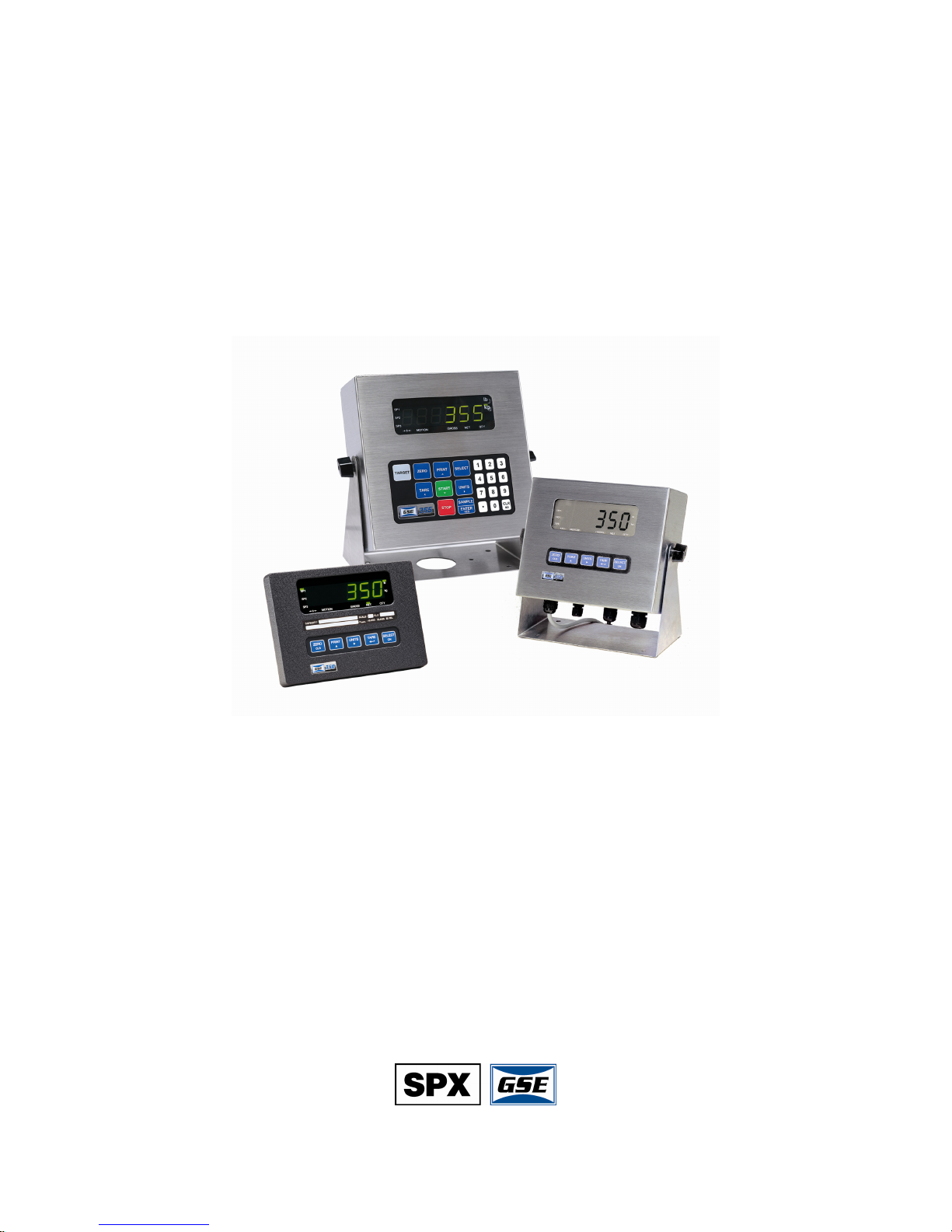
GSE Model 350/355
DIGITAL WEIGH INDICATOR
Technical Reference Manual
Flash Version
3.0
Page 2

Page 3

Model 350/355
Technical Reference Manual
Flash Version
3.0
Page 4

GSE 350/355 Digital Weigh Indicator Technical Reference Manual
Copyright © 2007 SPX GSE. All rights reserved.
Published by:
SPX GSE
1525 Fairway Circle
Allen Park, MI 48101
USA
Information in this Technical Manual is subject to change without notice due to correction or
enhancement. The information described in this manual is solely the property of GSE. No part of
this manual may be reproduced or transmitted in any form or by any means, electronic or
mechanical, including photocopying and recording and sold for any monetary figure without the
express written permission of GSE.
GSE Locations
SPX GSE
1525 Fairway Circle
Allen Park, MI 48101
U.S.A.
Phone: (800) 755-7875
www.gse-inc.com
SPX GSE Amprobe Europe GmbH
Phone: +49 (0) 2161-59906-11
Fax: +49 (0) 2161-59906-20
Page 5

Table of Contents
CHAPTER 1: INTRODUCTION................................................................................................... 1
S
TANDARD FEATURES...................................................................................................................... 1
SPECIFICATIONS ............................................................................................................................... 1
ISPLAY........................................................................................................................................... 3
D
LED Display................................................................................................................................ 3
LCD Display ............................................................................................................................... 4
Annunciators ............................................................................................................................... 4
350
KEYPAD .................................................................................................................................... 4
KEYPAD .................................................................................................................................... 6
355
Weigh Mode Functions ............................................................................................................... 7
Entering a Tare Value (Model 350)............................................................................................ 8
Entering a Tare Value (Model 355)............................................................................................ 8
CHAPTER 2: INDICATOR INSTALLATION............................................................................. 9
M
OUNTING....................................................................................................................................... 9
Desktop Mounting....................................................................................................................... 9
Panel Mounting (Die Cast Only) ................................................................................................ 9
Permanent Mounting ................................................................................................................ 10
Outline Drawings...................................................................................................................... 10
WIRING.......................................................................................................................................... 12
Stainless Steel Model 350/355 .................................................................................................. 12
Die Cast Model 350 .................................................................................................................. 12
Load Cell Connections.............................................................................................................. 12
Serial Port Connections............................................................................................................ 13
Remote Key Connection............................................................................................................ 14
Remote Display Connections .................................................................................................... 15
Power Connection..................................................................................................................... 15
CHAPTER 3: OPTION INSTALLATION .................................................................................. 17
MODEL 350/355 OPTIONS .............................................................................................................. 17
Swivel Bracket........................................................................................................................... 17
Panel Mount Kit........................................................................................................................ 18
ANALOG CARD CONNECTIONS....................................................................................................... 19
Analog Connections .................................................................................................................. 22
Analog Board Diagnostic and Test Procedures ....................................................................... 23
ETPOINT CARD CONNECTIONS ..................................................................................................... 26
S
Setpoint Connections ................................................................................................................ 28
Setpoint Board Diagnostic and Test Procedures...................................................................... 29
RS-485
NETWORKING ................................................................................................................... 30
Network Connections ................................................................................................................ 31
MA CURRENT LOOP OPTION ..................................................................................................... 33
20
Bi-directional ............................................................................................................................ 33
Baud .......................................................................................................................................... 33
i
Page 6

Active/Passive ........................................................................................................................... 33
Isolation .................................................................................................................................... 33
Max Voltage .............................................................................................................................. 34
Connections............................................................................................................................... 34
Cable ......................................................................................................................................... 34
Connected Devices.................................................................................................................... 34
BATTERY POWER SUPPLY .............................................................................................................. 35
Mounting................................................................................................................................... 35
Connection ................................................................................................................................ 36
ON/OFF Switch ........................................................................................................................ 37
Battery Charging ...................................................................................................................... 37
Temperature Sensing ................................................................................................................ 38
Low Battery Indication ............................................................................................................. 38
Dead Battery Shutdown ............................................................................................................ 38
Automatic Shutdown ................................................................................................................. 38
INTERNATIONAL TRANSFORMER - IEC........................................................................................... 39
Specifications ............................................................................................................................ 39
Transformers Available ............................................................................................................ 39
IEC line cords Available........................................................................................................... 39
FIBER-OPTIC INTERFACE................................................................................................................ 40
CHAPTER 4: CONFIGURATION............................................................................................... 43
ENTERING THE SETUP MODE (MODEL 350) ................................................................................... 43
ENTERING THE SETUP MODE (MODEL 355) ................................................................................... 44
SELECTING A PARAMETER ............................................................................................................. 44
CHANGING A PARAMETER VALUE ................................................................................................. 46
Selection Parameters ................................................................................................................ 46
Key-In Parameters .................................................................................................................... 46
SAVING PARAMETERS .................................................................................................................... 47
FACTORY DEFAULT ....................................................................................................................... 49
IST OF PARAMETERS .................................................................................................................... 50
L
Parameter Map Details............................................................................................................. 52
PRESET TRANSMIT SELECTIONS ..................................................................................................... 59
CUSTOM TRANSMIT ....................................................................................................................... 61
Elements of a Custom Transmit ................................................................................................ 61
Writing a custom transmit ASCII text file................................................................................. 61
Accessing Setup and Clearing Existing Custom Transmit........................................................ 61
Entering ASCII Text.................................................................................................................. 62
Entering ASCII Control Codes ................................................................................................. 62
Parameter Selection Numbers .................................................................................................. 64
Exiting Setup Mode and Saving Changes ................................................................................. 65
PARTS COUNTING .......................................................................................................................... 66
ANALOG OUTPUT SETUP................................................................................................................ 67
A
NALOG OUTPUT CALIBRATION .................................................................................................... 68
Entering Analog Calibration Values ........................................................................................ 68
Analog Output Example............................................................................................................ 69
ETPOINT SETUP ............................................................................................................................ 70
S
ii
Page 7

Activation Methods (General)................................................................................................... 70
Pre-acts (General) .................................................................................................................... 71
Learn Feature (General)........................................................................................................... 71
Pause Feature (General) .......................................................................................................... 71
Changing Targets from the Weigh Mode (General) ................................................................. 72
Example (General).................................................................................................................... 72
Bargraph (General) .................................................................................................................. 73
PERCENTAGE CHECK-WEIGHING ................................................................................................... 75
Setpoint Activation (ChecP)...................................................................................................... 75
Changing Targets from the Weigh Mode (Percentage Check-Weighing) ................................ 75
Example (ChecP) ...................................................................................................................... 76
FILL ............................................................................................................................................... 77
Activation Method (Fill) ........................................................................................................... 77
Pre-acts (Fill)............................................................................................................................ 77
Learn Feature (Fill).................................................................................................................. 78
Pause Feature (Fill).................................................................................................................. 78
Changing Targets from the Weigh Mode (Fill) ........................................................................ 78
Example (Fill) ........................................................................................................................... 78
BATCH ........................................................................................................................................... 79
Activation Method (Batch)........................................................................................................ 79
Pre-acts (Batch) ........................................................................................................................ 79
Learn Feature (Batch) .............................................................................................................. 79
Pause Feature (Batch) .............................................................................................................. 80
Changing Targets from the Weigh Mode (Batch)..................................................................... 80
Example (Batch)........................................................................................................................ 80
DISCHARGE.................................................................................................................................... 81
Activation Method (Discharge)................................................................................................. 81
Pre-acts (Discharge)................................................................................................................. 81
Learn Feature (Discharge) .......................................................................................................82
Pause Feature (Discharge).......................................................................................................82
Example (Discharge) ................................................................................................................ 82
OTH ............................................................................................................................................. 83
B
Activation Method (Both).......................................................................................................... 83
Pre-acts (Both).......................................................................................................................... 83
Learn Feature (Both) ................................................................................................................ 83
Pause Feature (Both)................................................................................................................ 84
Target Changes from the Weigh Mode (Both).......................................................................... 84
Example (Both) ......................................................................................................................... 84
ABSOLUTE CHECK-WEIGHING ....................................................................................................... 85
Setpoint Activation (ChecA)...................................................................................................... 85
Changing Targets from the Weigh Mode (ChecA) ................................................................... 85
Example (ChecA) ...................................................................................................................... 86
I
NDEPENDENT SETPOINT OPERATION............................................................................................. 87
Setpoint Activation (Independent)............................................................................................. 87
Changing Targets from the Weigh Mode (Independent) .......................................................... 88
Example (Independent) ............................................................................................................. 88
iii
Page 8

TARGET DEVIATION CHECK-WEIGHING ........................................................................................ 89
Setpoint Activation (ChecB)...................................................................................................... 89
Changing Targets from the Weigh Mode (ChecB) ................................................................... 89
Example (ChecB) ...................................................................................................................... 90
BATCH 2 ........................................................................................................................................ 92
Activation Method (Batch2)......................................................................................................92
Pause Feature (Batch2) ............................................................................................................ 92
Changing Targets from the Weigh Mode (Batch2)................................................................... 92
Example (Batch2)...................................................................................................................... 93
SETPOINT ERROR CODES................................................................................................................ 93
REMOTE KEY SETUP ...................................................................................................................... 94
REMOTE SERIAL OPERATION ......................................................................................................... 94
Display Capture Utility............................................................................................................. 95
IME AND DATE SETUP (MODEL 350)............................................................................................ 96
T
T
IME AND DATE SETUP (MODEL 355)............................................................................................ 97
RS-485 MULTI-DROP NETWORK SETUP AND OPERATION ............................................................. 98
Setup.......................................................................................................................................... 98
Operation .................................................................................................................................. 98
Network Protocol...................................................................................................................... 98
UPGRADE INDICATOR FIRMWARE .................................................................................................. 99
Prepare for upgrade ................................................................................................................. 99
Load Flash File......................................................................................................................... 99
REMOTE DISPLAY CONFIGURATION............................................................................................. 100
Master to Remote (Slave) Configuration ................................................................................ 100
Setup Master Indicator ........................................................................................................... 100
Setup Remote Indicator.......................................................................................................... 101
CONTROL (HAZARDOUS AREA) TO HUB (SAFE AREA) CONFIGURATION ..................................... 104
300 SERIES COMMAND CODES..................................................................................................... 105
ID NUMBER ENTRY...................................................................................................................... 107
CHAPTER 5: CALIBRATION ................................................................................................... 109
ETUP MODE CALIBRATION......................................................................................................... 109
S
FAST CALIBRATION...................................................................................................................... 109
PERFORMING CALIBRATION......................................................................................................... 110
ESTABLISHING ZERO.................................................................................................................... 110
First Zero ................................................................................................................................ 110
Last Zero ................................................................................................................................. 112
False Zero ............................................................................................................................... 114
Only Zero ................................................................................................................................ 116
Reset Calibration .................................................................................................................... 117
MULTI-POINT LINEARIZATION ..................................................................................................... 120
Examining Calibration Results ............................................................................................... 121
ESTABLISHING A SPAN ................................................................................................................. 121
E
XITING CALIBRATION ................................................................................................................ 122
CHAPTER 6: LEGAL FOR TRADE ......................................................................................... 123
NTEP REQUIREMENTS................................................................................................................. 123
iv
Page 9

NTEP PANEL MOUNT REQUIREMENTS ........................................................................................ 123
OMIL REQUIREMENTS................................................................................................................. 124
OTHER REQUIREMENTS................................................................................................................ 124
EALING AND AUDIT TRAILS ....................................................................................................... 125
S
Physical Seal........................................................................................................................... 125
Audit Trails ............................................................................................................................. 126
CHAPTER 7: TROUBLESHOOTING ...................................................................................... 129
E
RROR MESSAGES ....................................................................................................................... 129
Operational Errors ................................................................................................................. 129
Setup Mode Errors.................................................................................................................. 129
Hardware Errors .................................................................................................................... 130
Calibration Errors .................................................................................................................. 130
Communication Errors ........................................................................................................... 130
Miscellaneous Errors.............................................................................................................. 131
VIEWING SETUP ........................................................................................................................... 131
INFORMATION MODE PARAMETERS ............................................................................................. 132
A/D CALIBRATION PROCEDURE................................................................................................... 134
v
Page 10

Page 11

350/355 Technical Reference
CHAPTER 1: INTRODUCTION
Thank you for selecting the GSE Model 350/355 Indicator. The Model 350 and Model 355 continue the GSE
tradition of Excellence in Weighing and Counting Technology. A properly installed and maintained Model
350 or Model 355 will provide many years of reliable, accurate performance.
The chapters of this manual focus on various aspects of the Model 350/355:
Chapter 1: Introduction Features and Specifications
Chapter 2: Indicator Installation Mounting and wiring connections
Chapter 3: Option Installation Installing and setting up options
Chapter 4: Configuration Using the Model 350/355
Chapter 5: Calibration Calibrate the indicator to a scale
Chapter 6: Legal for Trade NTEP and OIML requirements
Chapter 7: Troubleshooting Troubleshooting help and error messages
Standard Features
The Model 350 and Model 355 include built-in functions that you can enable through the Indicator Setup.
Refer to Chapter 4: Configuration for information on the setup and operation of the following standard
functions:
• Check-weighing
• Fill, two-speed, single ingredient
• Batch, three ingredients, single-speed
• Loss-in weight, two-speed emptying
• Independent setpoints
• Parts counting
• Remote key operation
• Selectable, built-in data transmission formats
• Custom data transmissions
• Real time clock with battery backed time and date.
• Numeric keypad (Model 355 only)
• Easily update firmware via the RS-232 port
Specifications
PERFORMANCE
Full Scale (F.S.) Selectable 0 to 999,999
Resolution 20-bit A/D converter, 100,000d displayed,
A/D Conversion 60 Hz
Zero Track 0 – 100% of F.S.
Operating Temperature -10°C to +40°C
Units of Measure lb, kg, oz, g, lb oz
1,000,000d internal
1
Page 12

Chapter 1
ELECTRICAL
Power Requirement
350 Zinc Die Cast Enclosure
Input (J4): 12 – 26VAC / 12 – 36 VDC
One of four wall mount transformers supplied:
North American:
Input: 120VAC, 30W, 60 Hz
Output: 20VAC, 800mA
United Kingdom / Ireland:
Input: 230VAC, 28W, 50 Hz
Output: 20VAC, 800mA
Continental Europe:
Input: 230VAC, 28W, 50 Hz
Output: 20VAC, 800mA
IEC 320: (table top transformer with IEC 320 receptacle)
Input: 230VAC, 28W, 50 Hz
Output: 20VAC, 800mA
350/355 Stainless Steel Enclosure
Input (J10): 85 – 265VAC, 0.5A; 50/60 Hz (internal power supply version)
Input (J3): 10 – 36VDC, minimum 0.8A w/no options or 1.25A w/options installed (internal power supply
version)
Excitation Voltage 10 VDC
Excitation Current 180 mA max. / (6) 350Ω bridge
F.S. Signal Input 0.1 mV/V min – 20 mV/V max
Signal Connection 4 lead or 6 lead with sense
PROCESS CONTROL
Outputs See OPTIONS
Remote Input 1 momentary contact closure (100ms minimum)
TARE, PRINT, ZERO
COMMUNICATIONS
Serial RS232 bi-directional serial port
Data Output 16 selectable fixed-format transmissions or
2 custom formats (programmable via RS232)
Protocol Selectable
Baud Rate 150 – 115200 bps
DISPLAY
LED 6-digit weight display, 0.8” (22mm) height
11 LED annunciators for operational status
LCD 6-digit weight display, 1.0” (25.4mm) height
12 LCD annunciators for operational status
Built in LCD status bargraph
KEYPAD
350 Five key, durable elastomeric (rubber)
355 22 key, full numeric, durable elastomeric (rubber)
ENCLOSURE
Zinc Die Cast Black powder coat paint, self-standing on flat surface
Wall/Ceiling Mount Optional stainless steel swivel bracket
2
Page 13

350/355 Technical Reference
Shipping Weight 7 lb (3 kg)
Stainless Washdown stainless steel enclosure w/stainless steel swivel bracket (table,
wall or ceiling mount)
OPTIONS
Analog Output Module 0–10 VDC/5mA, 0–20mA/10V, 4–20mA/10V, electrically isolated, 16 bit
Relay Output Module Three (3) solid-state 24–280 VAC, 1A with up to 10 updates per second
Wall Mount Kit Swivel bracket/stand for zinc die cast enclosure
Panel Mount Kit Mounts zinc die cast enclosure to user panel
Cutout: 7.33” – 7.45”w x 5.25” – 5.37”h x 2.25”d
186.2 – 189.2mm x 133.4 – 136.4mm x 57.2mm
Two Option Mount Kit Mounts up to two option boards inside the stainless enclosure
Battery Power Supply Kits Two versions: one mounts inside the stainless steel enclosure, the other
Splash Shield Durable adhesive plastic that adheres to the front surface of the stainless
20 mA Current Loop Enables the communication port to be a digital 20 mA current loop port.
Fiber Optic Transceiver
resolution with up to 10 updates per second response time, mounts internal
to enclosure
response time, mounts internal to enclosure or three (3) 3– 60 VDC, 2A
mounts inside the die cast enclosure
steel enclosure model
Model 350/355 stainless steel, installs in the safe area and connects to a
Model 350/355. Allows setpoints and/or analog output options.
Communicates with hazardous area indicator via fiber-optic cable.
Display
The Model 350 and Model 355 indicators are available with either a six digit, 7-segment green LED display,
a six digit, 7-segment black LCD display or a 7-segment backlit LCD display. The Model 350 and Model 355
will display alphanumeric data, but due to the nature of 7-segment LEDs/LCD and the limitation of six digits,
some information is abbreviated.
All segments and annunciators are illuminated for a brief display test upon power up. The current gross
weight is then displayed in default units.
LED DISPLAY
The LED display is a six digit, 7-segment bright green LED screen with 12 annunciators to show
weight and status information. The SP1, SP2, and SP3 annunciators are red, green, and yellow. Also
there is an annunciator for a third unit under kg. Place the third unit label above the third annunciator
(the third unit is available on both the LED and LCD displays). See page 53 for third unit setup.
Figure 1: Model 350/355 LED Display
3
Page 14
Chapter 1
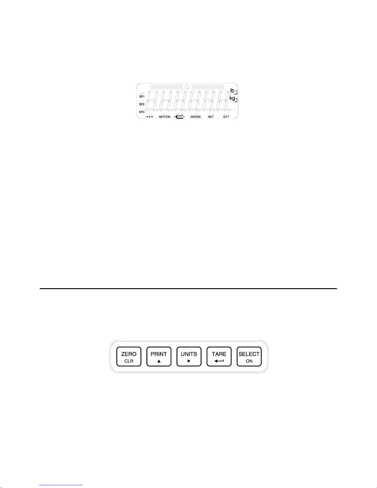
LCD DISPLAY
The LCD display is a six digit, 7-segment black LCD screen with 12 annunciators and a bargraph to show
the operational status.
Figure 2: Model 350/355 LCD Display
ANNUNCIATORS
Annunciators provide mode and status information. When illuminated, they indicate the following conditions:
SP1
SP2
SP3
¼0»
MOTION
GROSS
NET
QTY
lb
kg
Oz, lb oz, g
Lo
Setpoint #1 activated (relay 1 closed).
Setpoint #2 activated (relay 2 closed).
Setpoint #3 activated (relay 3 closed).
Displayed weight is at center-of-zero (± ¼ display graduation).
Scale is in motion. Motion inhibited transmits and motion inhibited setpoint activation will
be delayed until motion ceases.
Displayed value represents the current gross weight.
Displayed value represents the current net weight.
Displayed value represents the current piece quantity (Count)
The displayed value is represented in pounds.
The displayed value is represented in kilograms.
The displayed value is represented in either ounces, pound ounces or grams.
Illuminates when the battery reaches a low tolerance. LCD only
350 Keypad
The Model 350 offers a sealed 5-button elastomer keypad is used for operator input. Each key is assigned
two distinct functions. Various key combinations are also used. Each key has secondary functions; allowing
an operator to enter target values, perform piece samples, access setup parameters, etc.
A
Figure 3: Model 350 Keypad
4
Page 15

The Model 350 keypad performs different functions in the Weigh Mode, the Setup Mode, and the Calibration
Mode. Secondary functions for each key allow you to perform additional tasks.
Key Press Weigh Mode Count Mode Setup Mode
Performs a gross zero function
and/or clears an entry in progress.
Hold this key on power-up to
turn on the display regardless
of P420.
Performs a quantity zero
function and/or clears an entry
in progress.
Exits the Setup Mode and/or
answers “NO” to query prompts
and/or clears an entry in progress.
2
1
+
1 +
+ 1
Performs a print function and/or
‘scrolls’ through digits during
setpoint entry.
Toggles between ‘lb’ and ‘kg’
and/or advances cursor to next
entry position.
Performs an auto-tare function (if
enabled) and/or accepts an entry
in progress.
Toggles between display modes
and/or restores power to the
indicator (if auto-shutoff
enabled).
Access Setup Mode. Hold these
keys on power-up to bypass the
remote display mode.
No function. No function.
Absolute clear – clears an entry in
progress and/or clears the value of
a parameter.
Performs a print function
and/or ‘scrolls’ through digits
during setpoint entry.
Toggles through standard
sample sizes and/or begins a
new sample entry.
Performs an auto-tare function
and requests a piece sample
and/or accepts an entry in
progress.
Toggles between display modes
and/or restores power to the
indicator (if auto-shutoff
enabled).
Access Setup Mode. No function.
No function. Clears any entry in progress.
‘Scrolls’ through digits during
data entry.
Advances cursor to next entry
position and/or cycles prompts.
Accepts an entry in progress
and/or ‘scrolls’ through
parameter sub-set selections
and/or answers ‘YES’ to query
prompts.
Advances to the next setup
parameter.
Return to the previous setup
parameter.
+
+
2 + 1
+ 2
Backspace – erases the right-most
digit during data entry.
Extended gross. Extended gross. No function.
Turn off indicator by holding key
for approximately 1 second.
Reverse character scroll during
data entry.
Backspace – erases the rightmost digit during sample entry.
Turn off indicator by holding
key for approximately 1
second.
Reverse character scroll during
sample entry.
Backspace – erases right-most
digit during data entry.
Turn off indicator by holding key
for approximately 1 second.
Reverse character scroll during
data entry.
5
Page 16
Chapter 1
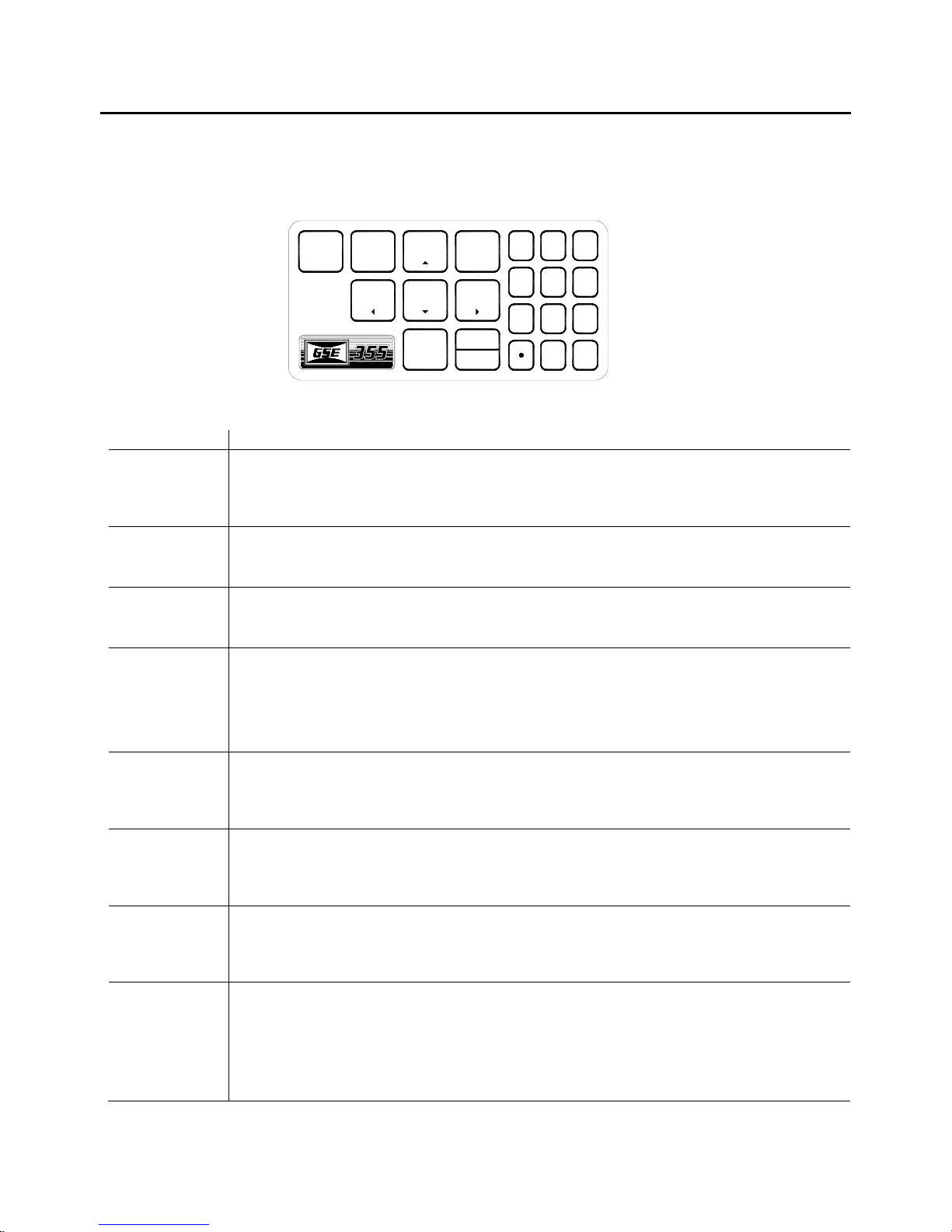
355 Keypad
The Model 355 keypad performs different functions in the Weigh Mode, the Setup Mode, and the Calibration
Mode. The number keys make entering a tare value or average piece weight easier.
TARGET
ZERO
PRINT
SELECT
TARE
START
STOP
UNITS
SAMPLE
ENTER
Figure 4: Model 355 Keypad
Key Press Weigh Mode Count Mode Setup Mode
"
Performs a gross zero function
and/or clears an entry in progress.
Performs a quantity zero function
and/or clears an entry in progress.
YES
123
4596
78
CLR
0
NO
Exits the Setup Mode and/or
answers “NO” to query prompts
and/or clears an entry in
progress.
2
#
!
(
Performs a print function and/or
‘scrolls’ through digits during
setpoint entry.
Toggles between ‘lb’ and ‘kg’
and/or advances cursor to next
entry position.
Performs an auto-tare function (if
enabled) and/or accepts an entry
in progress. If the tare weight is
known, key in the value and press
#.
Toggles between display modes
and/or restores power to the
indicator (if auto-shutoff
enabled).
Performs a sample. If a number is
keyed in before hand, it will be
used as the sample size. Accepts
an entry.
Clears an entry in progress. Hold
this key on power-up to turn on
the display regardless of P420.
Performs a print function and/or
‘scrolls’ through digits during
setpoint entry.
Toggles through standard sample
sizes and/or begins a new sample
entry.
Performs an auto-tare function
and/or accepts an entry in
progress.
Toggles between display modes
and/or restores power to the
indicator (if auto-shutoff
enabled).
Performs a sample. If a number is
keyed in before hand, it will be
used as the sample size.
Performs a quantity zero function
and/or clears an entry in progress.
‘Scrolls’ through digits during
data entry.
Advances cursor to next entry
position and/or cycles prompts.
Accepts an entry in progress
and/or ‘scrolls’ through
parameter sub-set selections
and/or answers ‘YES’ to query
prompts.
Advances to the next setup
parameter.
Accepts an entry.
Exits the Setup Mode and/or
answers “NO” to query prompts
and/or clears an entry in
progress.
If setpoints are enabled, causes a
process to start or resume. See
&
parameter 5003 on page 58 for
details on enabling the START
function.
6
If setpoints are enabled, causes a
process to start or resume. See
parameter 5003 on page 58 for
details on enabling the START
function.
No function
Page 17

Key Press Weigh Mode Count Mode Setup Mode
%
If setpoints are enabled, causes a
pause. Press % again to abort
the process. See parameter 5002
on page 58 for details on enabling
the STOP function.
If setpoints are enabled, causes a
pause. Press
the process. See parameter 5002
on page 58 for details on enabling
the STOP function.
% again to abort
No function
$
+
Wake up the indicator if in sleep
mode. Turn on the indicator if
power is off. Access the target
entry mode. See parameter 5000
on page 58 for details on enabling
the TARGET function.
Access Local Setup Mode. Hold
these keys on power-up to
bypass the remote display
mode.
Wake up the indicator if in sleep
mode. Turn on the indicator if
power is off. Access the target
entry mode. See parameter 5000
on page 58 for details on enabling
the TARGET function.
Access Local Setup Mode. No function
When the Model 355 keypad is installed with a new main board, the keypad must be initialized.
Hold down the
“EntHld”. To reestablish the keypad as a Model 350, hold down the
while power is applied by pressing the
( key while power is applied. If the keypad was enabled, the display will show
1 key of the 350 keypad
key.
WEIGH MODE FUNCTIONS
The Model 350 and Model 355 keypads have five primary Weigh Mode functions:
No function
"
2
#
!
Performs a gross zero and selects the gross mode
Initiates data transmission out the communication port
Toggles the units of measure between lb, kg, g, lb oz, oz
Tares any displayed weight and selects the net mode
Toggles the display between GROSS, NET, QUANTITY and setpoint TARGETS (if enabled)
7
Page 18

Chapter 1
ENTERING A TARE VALUE (MODEL 350)
If a tare value is known, it is possible to enter that value into the tare register. Follow the steps below. P167
must be enabled to use this feature.
1. From the gross or net mode press the
2. Use the
3. Press the
4. Repeat steps 2 and 3 until the desired number is showing on the display.
5. Press the
key to scroll in the first number.
2 key to move to the next digit.
1 key to accept the entered tare value.
key until tare is displayed.
ENTERING A TARE VALUE (MODEL 355)
If a tare value is known, it is possible to enter that value into the tare register. Follow the step below. P167
must be enabled to use this feature. Key in the known tare value and press
the net mode.
If the indicator is being installed in a legal for trade application, refer to Chapter 6 on page 123 for
details on the tare feature.
#. The display will access
8
Page 19

350/355 Technical Reference
(
)
(
)
CHAPTER 2: INDICATOR INSTALLATION
This chapter contains information necessary for proper installation of the Model 350 and Model 355. Please
review these instructions before installing the indicator.
High voltages may exist within the enclosure. To prevent the risk of electrical shock, ALWAYS unplug the
Model 350/355 when opening the enclosure. Installation and servicing of the Model 350/355 should be
performed only by authorized and qualified service personnel.
For information on installing options, see Chapter 3: Option Installation. For NTEP and OIML details, see
Chapter 6: Legal-for-Trade.
IMPORTANT! The 350 Series indicators do not include an on/off switch and therefore must be
installed near a power outlet socket that is easily accessible and in keeping with UL/CSA Safety
Standards.
INFORMATION IMPORTANT! Prendre note que les contrôleurs de serie 350 ne sont pas munis
d'interrupteurs "Marche / Arrêt". Par conséquent, il devront être installés près d'une source
d'alimentation secteur accessible pour demeurer sous les exigences des normes de sécurité
UL/CSA.
Mounting
The standard Model 350 zinc die cast enclosure is a NEMA1 (IP 20) equivalent. The Model 350/355
stainless steel enclosure meets NEMA 4X type specifications.
When choosing a mounting location for the Model 350 die cast, ensure that the unit is not installed in a
washdown area or conductive dust environment.
DESKTOP MOUNTING
The stainless steel enclosure is designed for desktop mounting. The 350 die cast may be installed as a
desktop unit with the optional mounting bracket 24350B-301C0 (refer to Figure 5 for installation details).
When set on a flat surface, the front face is angled for easy viewing. All wiring enters from the rear and can
be secured with the included screw mounted cable ties.
PANEL MOUNTING (DIE CAST ONLY)
The optional panel mount kit allows for the zinc die cast enclosure to be installed in a user panel. The panel
mount kit is only available in die cast not in stainless steel. Allow for 2.00” (57.2mm) depth behind the panel
surface. See Panel Mount Kit on page 18 for more details.
PANEL
5.25” – 5.37”
133.4 – 136.4mm
7.33” – 7.45”
186.2 – 189.2mm
CUTOUT
9
Page 20
Chapter 2
PERMANENT MOUNTING
The optional mounting bracket allows the zinc die cast enclosure to be securely fastened to another surface.
The bracket is attached to the indicator with two thumbscrews and can be swiveled to an optimal viewing
angle.
Figure 5: Model 350 Zinc Die Cast with Optional Mounting Bracket
OUTLINE DRAWINGS
Figure 6: Model 350 Zinc Die Cast Dimensions
10
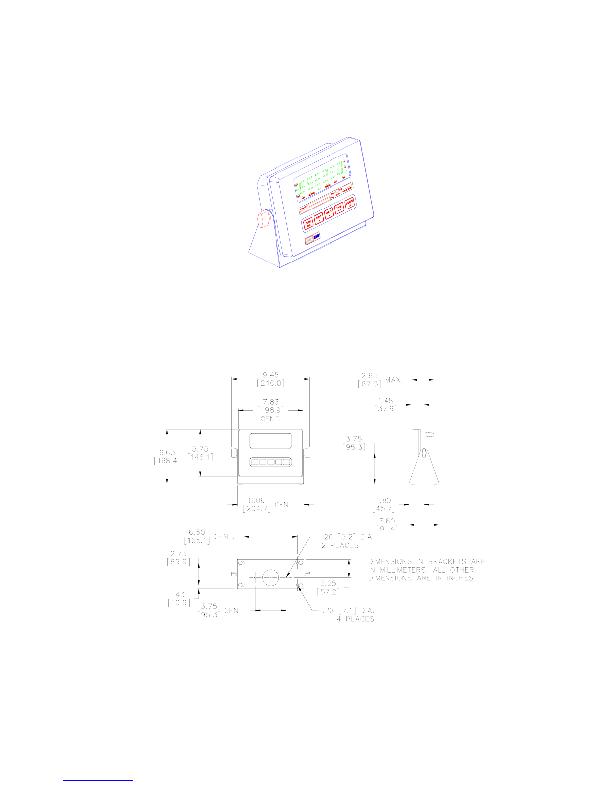
Page 21
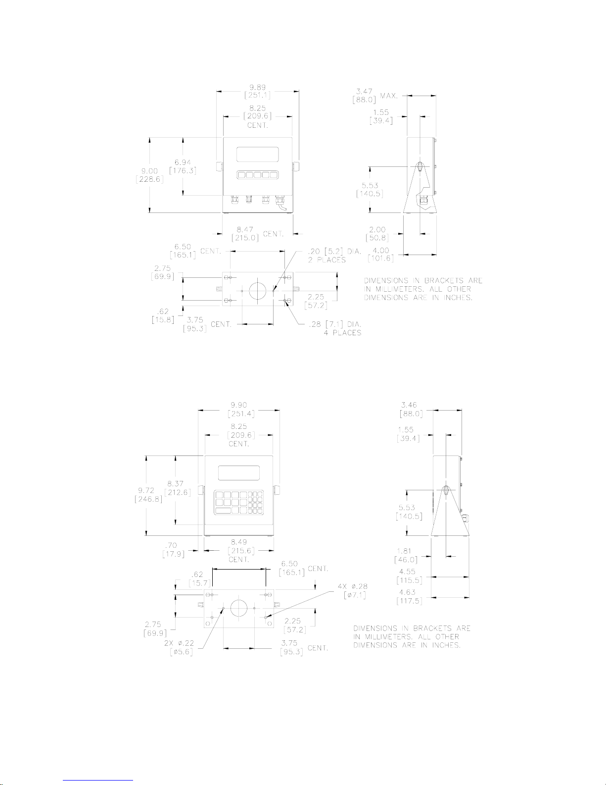
350/355 Technical Reference
Figure 7: Model 350 Stainless Steel Dimensions
Figure 8: Model 355 Stainless Steel Dimensions
11
Page 22
Chapter 2
Wiring
Wiring a load cell or communication port is simple on both the die cast and stainless steel models. Refer to
the information in this section for more details.
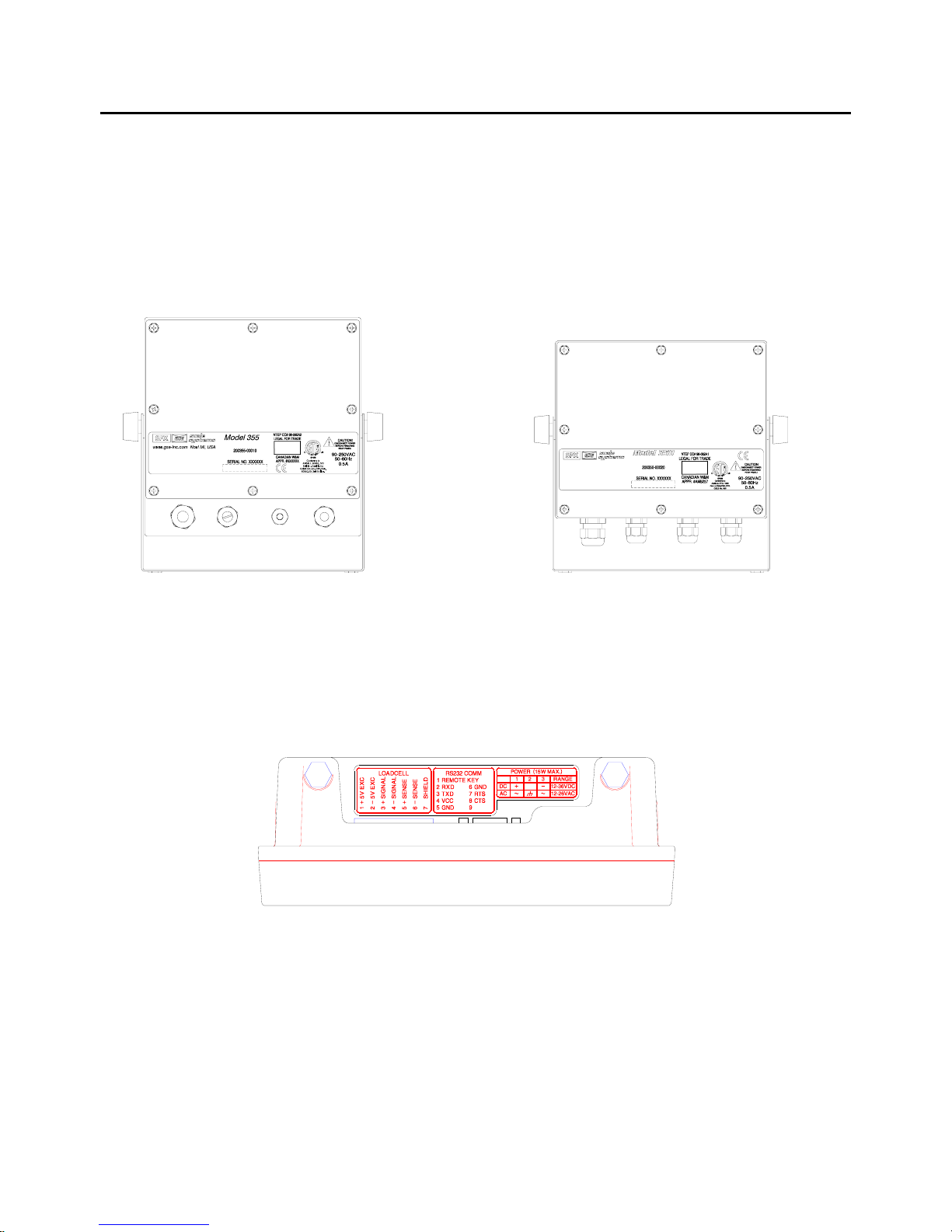
STAINLESS STEEL MODEL 350/355
The stainless steel models must be wired through the strain reliefs located on the bottom or rear of the
enclosure and connected to the main board. Refer to Figure 9 and Figure 10.
Figure 9 : Model 355 SS Rear Figure 10: Model 350 SS Rear
GSE INC. a division of SPX Corp.
www.gse-inc.com MADE IN USA
DIE CAST MODEL 350
A description of all wiring terminals is included on the bottom label of the zinc die cast enclosure as shown in
Figure 11.
Figure 11: Model 350 Zinc Die Cast Enclosure Wiring Label
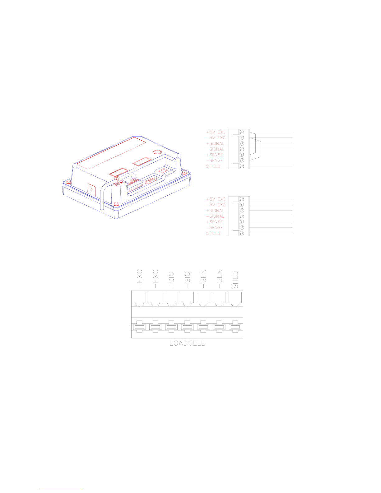
LOAD CELL CONNECTIONS
A high quality braided shield cable with 16 to 24 AWG stranded wire is recommended for load cell or
summing box connections. Secure the cable by the cable tie on the die cast model, or route it through the
strain relief supplied on the back of the internal power supply models (see Figure 12). Either four or six
conductor cables can be used.
12
Page 23
350/355 Technical Reference
Do not tin the ends of the load cell wire! A terminal connection free from the effects of vibration
and oxidation can be assured only if the load cell terminals securely grip a bare, stranded wire.
When using four conductor cables, (+ Excitation) must be connected together with (+ Sense), and (Excitation) must be connected together with (- Sense) on the Model 350 die cast. Sense jumpers are
standard on the Model 350/355 Stainless Steel (E3 and E4). Utilizing the (+) and (-) Sense leads of six
conductor cables provides compensation for variations in the excitation voltage due to resistance changes in
the cable.
Figure 12: Model 350 Cable Tie on Die Cast & Load Cell Connection (J8)
Figure 13: Model 350/355 Stainless Steel Load Cell Connector (J10)
SERIAL PORT CONNECTIONS
Before connecting to the serial port, consideration should be given to the communication protocol and to any
remote key requirements. For information on remote key operation, refer to Remote Key Operation on page
97. Use Table 1: Serial Port Connections to determine proper wiring to the communication port.
Communication connections are made through the DB9 male connector on the rear of the enclosure or a
pigtailed cable through a strain relief (internal power supply model on J6 comm connector). The cable
should be 20 to 28 AWG with a braided or foil shield for either model type. For maximum noise immunity on
the die cast model, use a mating DB9 connector with a metal hood and a braided shield cable. Ensure that
the braid makes good connection with the hood. The maximum recommended cable length is 50 feet (15
13
Page 24
Chapter 2
meters). However, much longer connections are possible if using a properly shielded, low-capacitance
cable.
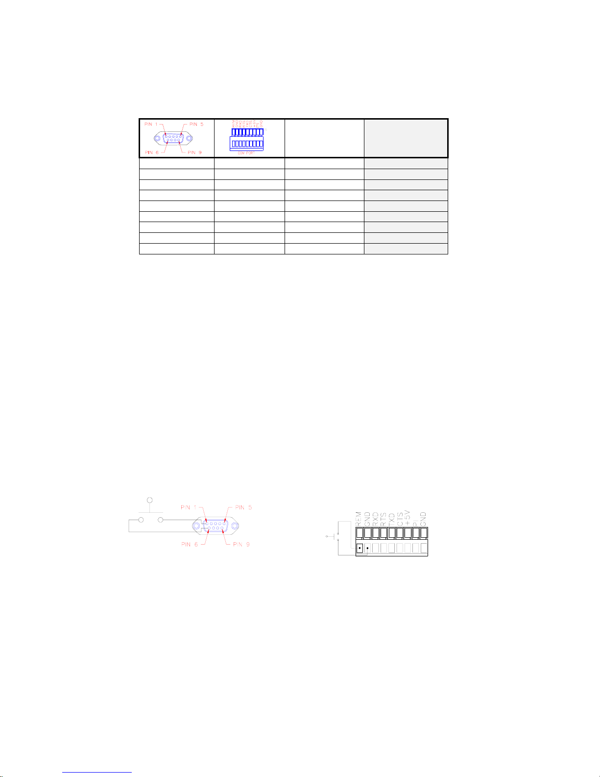
Table 1: Serial Port Connections
Description
1
2
3
4
5
6
7
8
9
REM Remote Key REMOTE KEY
RXD Receive RXD
TXD Transmit TXD
+5V +5 VDC
GND Digital Ground GND
GND Digital Ground GND
RTS Request-to-Send RTS
CTS Clear-to-Send
I/O Do Not Connect
Label
(Die cast encl. only)
VCC
CTS
REMOTE KEY CONNECTION
A remote key may be connected to the Model 350/355 communication port to provide remote activation of
print, tare, or zero functions.
The connection for the remote key input is between pin 1 and pin 6 of the DB9 communication port
connector (see Figure 15 for die cast, Figure 14 for stainless). A two-conductor shielded cable between 28
and 20 AWG is recommended. The input requires a contact closure from a push-button switch, a ‘dry’ relay
contact, a photo-eye, and a proximity sensor or other such device. A closure initiates the operation specified
at P800.
The open circuit voltage across the remote key pins is +5 VDC. A closed switch will conduct about 0.25 mA.
Therefore, a low-voltage switch with gold-plated contacts is recommended. A Mercury-wetted switch will
also work well. A minimum contact duration of 100 ms is required. Once invoked, the selected remote key
operation will not repeat until the contact is released and closed again.
Do not apply an external voltage to remote key terminals! Only a contact closure is
required to activate the remote key input.
Figure 15: Remote Key Connection
(Model 350 die cast)
14
Figure 14: Remote Key Connection
(Model 350 stainless and Model 355)
Page 25
350/355 Technical Reference
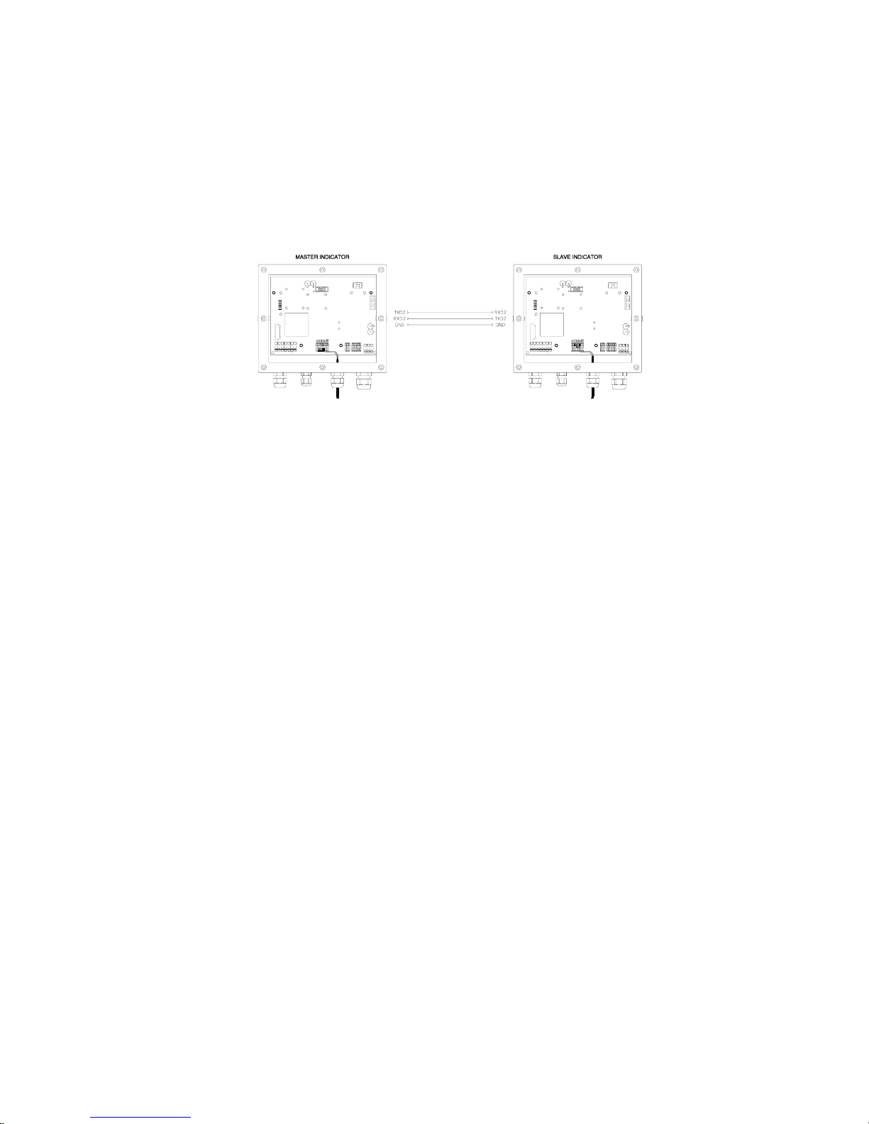
REMOTE DISPLAY CONNECTIONS
It is possible to connect one Model 350/355 indicator to another Model 350/355 and have the remote
indicator display a copy of the master indicator or customize the display of the remote (slave) indicator. The
keypad on both the master and slave indicators will operate. Refer to the drawing below to connect the
master indicator to the remote (slave) indicator. Refer to page 100 to configure the master and remote
(slave) displays. There are several different configurations for Master to remote (slave) indicator connection
and setup.
Figure 16: Master Indicator to Remote (slave) Indicator Connections
POWER CONNECTION
There are four ways to power the Model 350/355.
• 120 VAC wall mount transformer
• 12-36 VDC external source
• 12-26VAC external source
• Internal battery option
120VAC WALL MOUNT TRANSFORMER (DIE CAST 350)
An external wall mount transformer is supplied with the die cast Model 350 for connection to 120VAC, 60Hz
power and is plugged into J4 of the 350 die cast main board.
To connect the transformer:
The Model 350/355 does not include an on/off switch. In keeping with UL/CSA Safety Standards it
must be installed near an easily accessible power outlet. Note that the [ON] key does not
connect/disconnect the line voltage. It ‘awakens’ the Model 350/355 from a ‘sleep’ mode.
Do not cut the ground prong off the wall mount transformer!
1. Insert the polarized plug into the rectangular power connector (J4).
2. Press the plug firmly into the hole to ensure it is seated properly.
3. Plug the wall mount transformer into a nearby wall outlet. Use only a three-wire grounded outlet.
15
Page 26
Chapter 2
EXTERNAL AC OR DC POWER SUPPLY (DIE CAST 350)
The Model 350 die cast may be powered by an external 12-36 VDC or 12-26 VAC power source. The power
supply should have a minimum current rating of 800mA with no options installed, a minimum current rating
of 1.25A with options installed. Recommended plugs are AMP MTA .156” or MOLEX .156”.
External DC power supply cable GSE P/N 22-30-35459 plugs into the Model 350 die cast unit rear
connector with bare wires on the other end.
An internal option battery module is available, GSE part number 24350B-120B1. Refer to page 35 for
details on installation.
Pin 1 Pin 2 Pin 3 Range
DC
AC L GND N
+
N/C
12-36 VDC
-
12-26 VAC
50/60 HZ
Figure 17: Model 350 Die Cast Power Connections
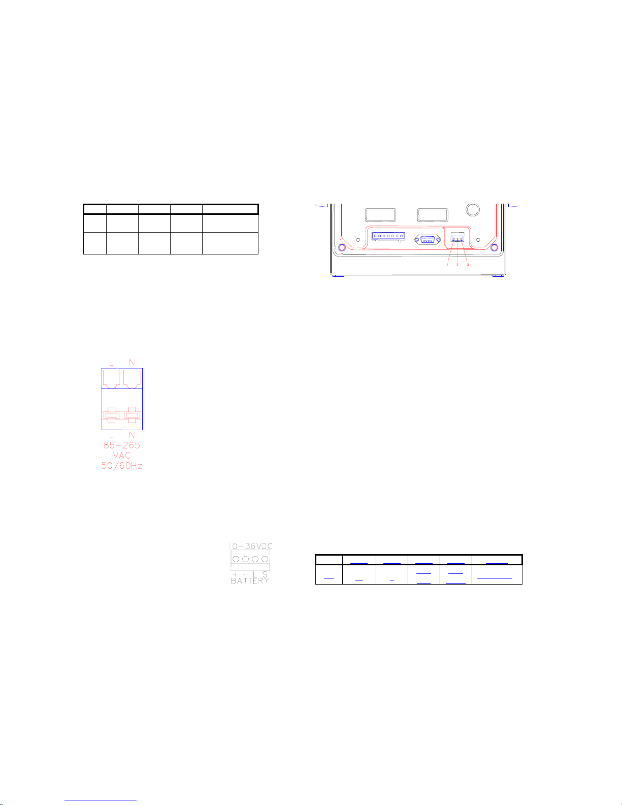
INTERNAL AC OR DC POWER SUPPLY (STAINLESS STEEL 350/355)
Figure 18: Model
350/355 Internal Power
Supply Model AC
Connections (J14)
The Model 350/355 internal power supply model may be powered by an external
VAC power source connected to (J14) on the main board. Input power can be 85
– 265VAC, 0.5A; 50/60 Hz. See the internal AC power connector as shown in
Figure 18. The ground wire is connected to a stud on the enclosure.
The Model 350/355 internal power supply model may be powered by an external
10-36 VDC power source connected to (J12) on the main board (also see Battery
Power Supply on page 35). The power supply should have a minimum current
rating of 800mA with no options installed, a minimum current rating of 1.25A with
options installed.
Do not connect pins 3 or 4. The mating connector can be purchased from a local
electronics supplier. Recommended connectors are GSE PN: 26-20-3365 (24
AWG) or GSE PN: 26-20-3366 (22 AWG) / AMP PN: 640441-3 (24 AWG) or AMP
PN: 640440-3 (22 AWG). Connector cover GSE PN: 26-20-3389 or AMP PN:
643075-3.
Pin 1 Pin 2 Pin 3 Pin 4 Range
DC
+ -
Low
Batt
Shut
Down
12-36 VDC
Figure 19: Model 350/355 Internal Power Supply Model DC Connections (J12)
16
Page 27

350/355 Technical Reference
Chapter 3: Option Installation
The capabilities of the Model 350 can be expanded with the use of one or more option kits. This chapter
provides installation procedures for these options.
Model 350/355 Options
The following options are available for the Model 350:
• Swivel Bracket Kit (die cast model) (GSE P/N 24350B-301C0)
Allows the indicator to be securely mounted to any surface.
• Panel Mount Kit (die cast model) (GSE P/N 24350B-300C0)
Allows the indicator to be easily mounted into existing cabinetry.
• 2 - Option Mounting Bracket (GSE P/N 24350B-302C0)
Provides for mounting up to two option boards (required for the stainless steel enclosure only).
• Analog Output Module (GSE P/N 24350B-203B0)
Provides an electrically isolated, 16-bit analog signal for connectivity to external devices.
• Setpoint Control Module (GSE P/N 24350B-100C1)
(GSE P/N 24350B-100C2)
Provides three discrete outputs for direct control of operation equipment.
• Battery Power Supply (die cast) (GSE P/N 24350B-120B1)
(stainless steel) (GSE P/N 24350B-121B1)
Provides portability for the Model 350/355.
• 20 mA Current Loop (GSE P/N 24660B-404A0)
Provides a digital 20 mA current loop.
• RS-485 Network (stainless steel model) (GSE P/N 24660B-401A0)
Allows the indicator to communicate with hazardous area indicator via fiber-optic cable.
SWIVEL BRACKET
The Model 350 die cast has an optional stainless steel swivel bracket for secure mounting to desks,
tabletops or walls. See the Mounting section beginning on page 9 for instructions on mounting the Model
350/355 using the swivel bracket.
17
Page 28
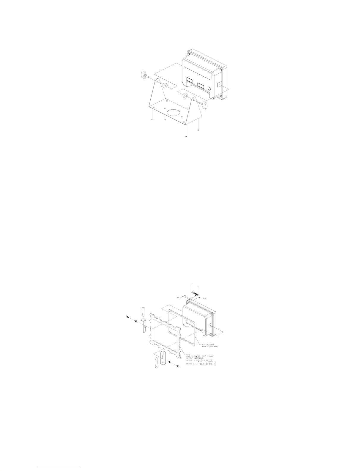
Figure 20: Swivel Bracket Installation (Die Cast Model)
To install the swivel bracket:
1. Unpack the Swivel Bracket option.
Be sure that all parts shown in Figure 20 are accounted for.
2. Remove the two plastic Heyco plugs.
The plugs are located in the threaded bracket mounting holes on either side of the indicator. Be careful not
to scratch the finish of the indicator when removing these plugs.
Chapter 3
3. Place the two spacers against the bracket and then insert the thumb screws.
The spacer and bracket holes should align with the bracket mounting holes on either side of the enclosure.
PANEL MOUNT KIT
The Panel Mount Kit provides an easy way to mount the indicator into new or existing cabinetry. See Figure
21 for detailed instructions on panel mounting the Model 350 die cast. See also NTEP Panel Mount
Requirements on page 123 for additional panel mounting NTEP requirements.
Figure 21: Model 350 Panel Mount Installation (Die Cast Model)
18
Page 29

350/355 Technical Reference
To install the Model 350 Panel Mount Kit:
1. Unpack the Panel Mount Kit.
Be sure that all parts shown in Figure 21 are accounted for.
2. Remove the two plastic Heyco plugs.
The plugs are located in the threaded bracket mounting holes on either side of the indicator. Be careful not
to scratch the finish of the indicator when removing these plugs.
3. Place the adhesive gasket around the panel cutout.
This step is optional. The gasket should be adhered onto the outside of the panel and centered around the
cutout.
4. Place the Model 350 through the panel cutout.
This step may require a second person to hold the indicator in place. The indicator should be centered
inside the cutout.
5. Using two small screws and star washers, attach the two panel mount brackets. The center holes of the
brackets should align with the threaded bracket mounting holes on either side of the indicator. The two
brackets should angle away from the indicator. Apply pressure on the mounting brackets in the directions
shown in Figure 21. This will ensure the indicator is drawn firmly against the panel.
6. Using four long screws and four lock-nuts, secure the indicator to the panel. Thread the lock-nuts onto the
screws so that they will not interfere with tightening the screws into the threaded bracket holes. Evenly
tighten the four screws until they are snug. Do not over-tighten. Now thread the lock-nuts down until they
are snug against the bracket.
7. Drill 1/16 (0.0625) diameter pilot hole on the front of the enclosure for the serial number label.
8. Add the serial number to the label.
9. Install the label by tapping the pins through the label into the front enclosure.
Analog Card Connections
The 16-bit electrically-isolated analog output module provides a highly accurate analog signal, proportional
to weight. This signal can be used for interfacing to PLCs, chart recorders, and other such devices.
See Analog Output Setup on page 67 for analog output software configuration details.
The Model 350/355 contains components which could be damaged by Electrostatic Discharge
(ESD) if serviced improperly. Use proper ESD precautions (wear a wrist strap connected to
ground, use grounded work stations, etc.) when opening the enclosure.
High voltages may exist within the enclosure! To prevent the risk of electrical shock, ALWAYS
unplug the Model 350/355 when opening the enclosure. Installation and servicing of the Model
350/355 should be performed by authorized and qualified service personnel only.
Never connect or disconnect option board cables while the indicator is powered. Doing so may
result in circuit board damage.
19
Page 30

To install the Analog Output Module (350 die cast model):
1. Open the indicator. Remove the four screws from the back of the unit. It may
help to remove the swivel bracket, if installed.
2. Place the back of the indicator, open side down, on a firm surface. Using a
hammer and screwdriver, remove the appropriate knock-out.
It helps to place the screwdriver tip on the knockout pad, rather than in the
groove. The knock-outs do not require much force to remove. If only
installing one option, the left knock-out (as viewed from the rear) should be
removed. A small file may be used to remove any burrs.
3. Flip the back cover over and place the Analog Output Module, component
side down, over the four mounting holes. Install four 10mm screws to a
minimum of 8 in/lb of torque.
Chapter 3
Be sure the cable is already attached before installing the card. Also, be sure
the cable is attached to the left-most connector (as viewed from the
component side of the option board). The second connector is for ‘daisychaining’ another option card. The screws used to mount the option card are
self-tapping and will require added torque when first installed.
4. Attach the loose end of the cable to the serial I/O connector (J7) on the main
board or the open connector of a previously installed option card.
J7 is a 10-pin polarized connector. Be sure the cable is not twisted when installed. If this is a second option
card, route the cable to the open connector of the first option card.
5. Reinstall the back cover. Tighten the four screws to a minimum of 8 in/lb torque.
Be sure to avoid ‘pinching’ the cable between the housing halves. Affix all appropriate labels to the back of
the indicator.
To install the Analog Output Module without mounting bracket (Model 350/355 Stainless):
If only one option is being installed in a fiber-optic hub indicator use the following instructions. If two
options are being installed along with a fiber-optic option an option mounting plate is required. Refer
to page 27 for installation instructions.
1. Open the indicator.
Remove the eight screws from the back of the unit.
2. Locate the option mounting holes by lining up the option card with the four holes to the left of the power
supply section on the main board.
Figure 22: Option Board
Installation (Die Cast Model 350)
This is where the first option card should be installed.
20
Page 31

350/355 Technical Reference
3. Install (4) nylon standoffs supplied with the option kit into the
thru-holes on the main board. See Figure 27.
4. Place the option card on the (4) nylon standoffs installed in step 3.
5. Fasten the option card to the standoffs with the (4) nylon nuts
supplied with the option kit.
Tighten the stand-offs gently with a 8 mm hex nut driver.
If this is the only option card being installed, attach the loose end
of the cable on the option card to the serial I/O connector (J3) on
the main board. J3 is a 10-pin polarized connector. Skip to step 6.
~ OR ~
If a second option is being installed, locate the option mounting
holes surrounding the A/D can on the main board. Follow steps 3 5 to install the second option card.
Connect the loose end of the cable of the second option card to (J3) of the main board. Connect the loose
end of the cable of the first option card to J1 of the second option card.
6. Route the cables being connected to the option cards through the available strain-relief(s). Make sure to
connect cable conductors to the proper terminals before closing the unit.
7. Reinstall the back cover. Tighten the eight screws securely to create a good seal. Be sure to avoid
‘pinching’ the cable between the housing halves.
To install the Analog Output Model with Option Mounting Bracket (Model 350/355 Stainless):
1. Open the indicator.
Remove the eight screws from the back of the unit.
2. Locate the three studs and one thru-hole on the 350 main board
that the option mounting bracket will be attached to. See Figure
24. Remove the nuts from the three studs on the main board.
It may help to position the option mounting bracket over the 350
main board to locate the three studs and one thru-hole.
3. Install the nylon stand-off supplied with the option bracket kit into
the thru-hole on the option bracket. See Figure 24.
Figure 23: Option Board Installation
Flash Version
The thru-hole is located on the option bracket, towards the center
of the board, on the irregular flanged section (a smaller hole than
the others on the bracket) that would be positioned towards the
power supply regulator (U11) with a flanged heat sink on it.
4. Install the three hex stand-offs onto the studs on the main board.
Tighten the stand-offs gently with a 6 mm hex nut driver.
5. If the option card is being installed in a Model 355, unplug the
keypad cable from the serial I/O connector (J17) on the main board
and plug the cable into the option connector of the option card (J1).
Plug the cable from J3 of the option card to J17 of the main board.
~ OR ~
If this is the first option card, attach the loose end of the cable to the serial I/O connector (J7) on the main
board. Let the card gently hang over to the outside of the enclosure until mounting. J7 is a 10-pin polarized
connector.
Figure 24: Option Board Installation
(Stainless Model 350/355)
21
Page 32

Chapter 3
This step is not necessary if this is the second card installed.
6. Position the nylon stand-off (attached to the bracket) into the hole on the main board while routing the threads
of the other hex stand-offs thru the holes on the bracket, while pressing down over the nylon stand-off until it
snaps into place.
Line-up the three other hex stand-offs into the bracket thru-holes first before securing the nylon stand-off into
the main board thru-hole.
7. Secure the bracket into position with the hex nuts supplied with the kit. Do not over tighten.
8. Place one set (four pieces) of the nylon sleeve type stand-offs onto the four studs of the option bracket. Place
the Analog Output Module, component side up, onto the nylon sleeve stand-offs. Install four hex nuts and
secure gently.
Select the four studs closest to the (J7) connector of the main board to add the four sleeve stand-offs. Be sure
the cable is already attached to (J7) on the main board before installing the card. Also be sure the cable is
attached to the right-most connector (J3) (as viewed from the component side of the option board). The second
connector (J1) is for ‘daisy-chaining’ another option card. The additional mounting hardware is supplied with
the option bracket kit. This hardware should be saved for future use if not being used.
9. Route the analog cable through the available strain-relief.
Make sure to connect cable conductors to the proper terminals before closing the unit.
10. Reinstall the back cover. Tighten the eight screws securely to create a good seal.
Be sure to avoid ‘pinching’ the cable between the housing halves.
ANALOG CONNECTIONS
Table 2: Analog Output Connections
Pin Connection Name Description
1 Earth Ground Non-isolated earth ground (future use).
2 + 5 VDC Isolated 5 volt source (future use).
3 Isolated Ground Provides an isolated ground connection.
4 Vout Used for the 0-10 VDC analog signal output.
5 Isolated Ground Provides an isolated ground connection.
6 Iout Used for 4-20 or 0-20 mA analog signal output.
350 DIE CAST
Place this label on the rear of the indicator above the analog option knockout. Wire the option connector in accordance
with the label (left to right).
22
Page 33

350/355 Technical Reference
350/355 STAINLESS STEEL
Cut off the text “ANALOG OUTPUTS” from the label and place it on the connector shown below (apply to the
area just under the field external wire terminals).
ANALOG BOARD DIAGNOSTIC AND TEST PROCEDURES
To test the 0-10v output mode:
The following test procedures affect the analog output signal levels. Be sure to disconnect all
peripheral devices attached to the analog option card.
Test equipment needed: precision DC voltmeter, 500 ohm precision resistor. The 500 ohm
resistor must meet the following specifications: .01% tolerance and 5ppm temperature
coefficient.
This test procedure requires that the initial analog option calibration procedure has been
completed
1. Enter the Setup Mode (see Setup Mode on page 43).
Chngs Poss!
P110.-- ~ F.S.= ~ 100.00
2. Attach the voltmeter + (red) lead to pin 3 (0-10VDC) and the - (black) lead to pin 2 (ISOLATED GND)
of the Analog Output connector.
3. Key in
Test ~ 0-10v
Per P176
4. Press
!.
1 or ( to set the output to 0%.
0-10v ~ 0P
0.00 VDC
5. Press
0-10v ~ 25P
2.50 VDC
6. Press
0-10v ~ 50P
5.00 VDC
7. Press
0-10v ~ 75P
7.50 VDC
8. Press
0-10v ~ 100P
1 or ( to increase the output to 25%.
1 or ( to increase the output to 50%.
1 or ( to increase the output to 75%.
1 or ( to increase the output to 100%.
1.00 VDC
23
Page 34

To test the 0-20mA output mode:
Voltmeter readings are based on the use of a 500 ohm precision resistor. Caution! Do not
exceed 500 ohms.
1. Enter the Setup Mode (see Setup Mode on page 43).
Chngs Poss!
P110.-- ~ F.S.= ~ 100.00
2. Attach the precision resistor to pin 5 and pin 6.
3. Attach the voltmeter + (red) lead to pin 6 (0-20 mA) of the analog output connector.
4. Attach the voltmeter - (black) lead to pin 5 (ISOLATED GND) of the Analog Output connector.
Chapter 3
5. Key in
Test ~ 0-20A
Per P176
6. Press
0-20A ~ 0P
0.00 V
7. Press
0-20A ~ 25P
2.5 V
8. Press
0-20A ~ 50P
5 V
9. Press1 or ( to increase the output to 75%.
0-20A ~ 75P
7.5 V
10. Press
0-20A ~ 100P
10 V
! (see Setup Mode on page 43).
1 or ( to set the output to 0%.
1 or ( to increase the output to 25%.
1 or ( to increase the output to 50%.
1 or ( to increase the output to 100%.
To test the 4-20mA output mode:
Voltmeter readings are based on the use of a 500 ohm precision resistor.
Caution! Do not exceed 500 ohms.
1. Enter the Setup Mode (see Setup Mode on page 43).
Chngs Poss!
P110.-- ~ F.S.= ~ 100.00
2. Attach the precision resistor to pin 5 and pin 6.
3. Attach the voltmeter + (red) lead to pin 6 (4-20 mA) of the analog output connector.
4. Attach the voltmeter - (black) lead to pin 5 (ISOLATED GND) of the Analog Output connector.
24
Page 35

350/355 Technical Reference
5. Key in ! (see Setup Mode on page 43).
Test ~ 4-20A
Per P176
6. Press
4-20A ~ 0P
2 V
7. Press
4-20A ~ 25P
4 V
8. Press
4-20A ~ 50P
6 V
9. Press
4-20A ~ 75P
8 V
10.
4-20A ~ 100P
10V
1 or ( to set the output to 0%.
1 or( to increase the output to 25%.
1 or ( to increase the output to 50%.
1 or( to increase the output to 75%.
Press 1 or ( to increase the output to 100%.
25
Page 36

Chapter 3
Setpoint Card Connections
Using one of the software setpoint configurations (see General Setpoint Setup on page 70) in conjunction
with the setpoint option board gives the Model 350/355 the ability to directly control external devices such as
valves, relays, actuators, etc.
There are up to three setpoint outputs available. The activation and deactivation is controlled by the setpoint
configuration. The outputs are capable of driving up to 20-280VAC & 2 Amp at 3-60VDC @ 1A. The solid
state relays are normally open (NO) contacts.
See General Setpoint Setup on page 70 for setpoint software configuration details.
The Model 350/355 contains components which could be damaged by Electrostatic Discharge
(ESD) if serviced improperly. Use proper ESD precautions (wear a wrist strap connected to
ground, use grounded work stations, etc.) when opening the enclosure.
High voltages may exist within the enclosure! To prevent the risk of electrical shock, ALWAYS
unplug the Model 350/355 when opening the enclosure. Installation and servicing of the Model
350/355 should be performed by authorized and qualified service personnel only.
Never connect or disconnect option board cables while the indicator is powered. Doing so may
result in circuit board damage.
To install the Setpoint Control Module (350 die cast):
1. Open the indicator.
Remove the four screws from the back of the unit. It may help to remove the swivel bracket, if installed.
2. Place the back of the indicator, open side down, on a firm surface. Using a hammer and screwdriver,
remove the appropriate knock-out.
It helps to place the screwdriver tip on the knockout pad, rather
than in the groove. The knock-outs do not require much force to
remove. If only installing one option, the left knock-out (as viewed
from the rear) should be removed. A small file may be used to
remove any burrs.
3. Flip the back cover over and place the Setpoint Control Module,
component side down, over the four mounting holes. Install four
10mm screws to a minimum of 8 in/lb of torque.
Be sure the cable is already attached before installing the card.
Also be sure the cable is attached to the left-most connector (as
viewed from the component side of the option board). The second
connector is for ‘daisy-chaining’ another option card. The screws
used to mount the option card are self-tapping and will require
added torque when first installed.
4. Attach the loose end of the cable to the serial I/O connector (J7) on
the main board or the open connector of a previously installed
option card.
J7 is a 10-pin polarized connector. Be sure the cable is not twisted when installed. If this is a second
option card, route the cable to the open connector of the first option card.
Figure 25: Option Board
Installation (Die Cast Model 350)
5. Reinstall the back cover. Tighten the four screws to a minimum of 8 in/lb torque.
Be sure to avoid ‘pinching’ the cable between the housing halves. Affix all appropriate labels to the back
of the indicator.
26
Page 37

350/355 Technical Reference
To install the Setpoint Control Module without mounting bracket (350/355 Stainless):
If only one option is being installed in a fiber-optic hub indicator use the following instructions. If two
options are being installed along with a fiber-optic option an option mounting plate is required. Refer
to page 27 for installation instructions.
1. Open the indicator.
Remove the eight screws from the back of the unit.
2. Locate the option mounting holes by lining up the option card with the four holes to the left of the power
supply section on the main board.
This is where the first option card should be installed.
3. Install (4) nylon standoffs supplied with the option kit into the
thru-holes on the main board. See Figure 27.
4. Place the option card on the (4) nylon standoffs installed in
step 3.
5. Fasten the option card to the standoffs with the (4) nylon nuts
supplied with the option kit.
Tighten the stand-offs gently with a 8 mm hex nut driver.
If this is the only option card being installed, attach the loose
end of the cable on the option card to the serial I/O connector
(J3) on the main board. J3 is a 10-pin polarized connector.
Skip to step 6.
~ OR ~
If a second option is being installed, locate the option
mounting holes surrounding the A/D can on the main board.
Follow steps 3 - 5 to install the second option card.
Connect the loose end of the cable of the second option card to
(J3) of the main board. Connect the loose end of the cable of
the first option card to J1 of the second option card.
6. Route the cables being connected to the option cards through the available strain-relief(s). Make sure to
connect cable conductors to the proper terminals before closing the unit.
7. Reinstall the back cover. Tighten the eight screws securely to create a good seal. Be sure to avoid
‘pinching’ the cable between the housing halves.
To install the Setpoint Control Model with mounting bracket (350/355 Stainless):
1. Open the indicator.
Remove the eight screws from the back of the unit.
2. Locate the three studs and one thru-hole on the main board that the option mounting bracket will be
attached to. See Figure 27. Remove the nuts from the three studs on the main board.
It may help to position the option mounting bracket over the 350 main board to locate the three studs and
one thru-hole.
Figure 26: Option Board Installation
Flash Version
27
Page 38

Chapter 3
3. Install the nylon stand-off supplied with the option bracket kit into
the thru-hole on the option bracket. See Figure 27.
The thru-hole is located on the option bracket, towards the center
of the board, on the irregular flanged section (a smaller hole than
the others on the bracket) that would be positioned towards the
power supply regulator (U11) with a flanged heat sink on it.
4. Install the three hex stand-offs onto the studs on the main board.
Tighten the stand-offs gently with a 6 mm hex nut driver.
5. If the option card is being installed in a Model 355, unplug the
keypad cable from the serial I/O connector (J17) on the main board
and plug the cable into the option connector of the option card (J1).
Plug the cable from J3 of the option card to J17 of the main board.
~ OR ~
If this is the first option card, attach the loose end of the cable to
the serial I/O connector (J7) on the main board. Let the card gently
hang over to the outside of the enclosure until mounting. J7 is a 10pin polarized connector.
This step is not necessary if this is the second card installed.
6. Position the nylon stand-off (attached to the bracket) into the hole
Figure 27: Option Board
Installation (Eprom Version)
on the main board while routing the threads of the other hex stand-offs through the holes on the bracket,
while pressing down over the nylon stand-off until it snaps into place.
Line-up the three other hex stand-offs into the bracket thru-holes first before securing the nylon stand-off
into the main board thru-hole.
7. Secure the bracket into position with the hex nuts supplied with the kit. Do not over tighten.
8. Place one set (four pieces) of the nylon sleeve type stand-offs onto the four studs of the option bracket.
Place the Setpoint Control Module, component side up, onto the nylon sleeve stand-offs. Install four hex
nuts and secure gently.
Select the four studs closest to the (J7) connector of the main board to add the four sleeve stand-offs. Be
sure the cable is already attached to (J7) on the main board before installing the card. Also be sure the
cable is attached to the right-most connector (J3) (as viewed from the component side of the option
board). The second connector (J1) is for ‘daisy-chaining’ another option card. The additional mounting
hardware is supplied with the option bracket kit. This hardware should be saved for future use if not
being used.
9. Route the cables being connected to the option cards through the available strain-relief(s). Make sure to
connect cable conductors to the proper terminals before closing the unit.
10. Reinstall the back cover. Tighten the eight screws securely to create a good seal. Be sure to avoid
‘pinching’ the cable between the housing halves.
SETPOINT CONNECTIONS
Table 3: Setpoint Control Connections
Pin
1 Line 1 Line voltage in for setpoint 1.
2 Load 1 Voltage out for setpoint 1.
3 Line 2 Line voltage in for setpoint 2.
4 Load 2 Voltage out for setpoint 2.
5 Line 3 Line voltage in for setpoint 3.
6 Load 3 Voltage out for setpoint 3.
Connection
Name
Description
28
Page 39

350/355 Technical Reference
350 DIE CAST
Place this label above the setpoint card knockout.
350/355 STAINLESS STEEL
Cut off the text “SETPOINT OUTPUTS” from the label and place it on the connector shown in Figure 23 (apply to the
area just under the field external wire terminals).
SETPOINT BOARD DIAGNOSTIC AND TEST PROCEDURES
This test procedure affects the setpoint output. Be sure to disconnect all peripheral devices
attached to the setpoint option card.
Test Equipment needed: Load device with power source.
To test the setpoint option card:
1. Enter the Setup Mode (see Setup Mode on page 43).
Chngs Poss!
P110.-- ~ F.S.= ~ 100.00
2. Key in
Test ~ Setpt
Load Device Inactive
3. Attach the load and power source in series with Setpoint 1 contacts.
4. Press
Test ~ Spt 1
Load Device Active
5. Attach the load and power source in series with Setpoint 2 contacts.
!.
1 or ( to activate only output #1.
6. Press
Test ~ Spt 2
Load Device Active
7. Attach the load and power source in series with Setpoint 3 contacts.
8. Press
Test ~ Spt 3
Load Device Active
1 or ( to activate only output #2.
1 or ( to activate only output #3.
29
Page 40

Chapter 3
)
)
RS-485 Networking
The Model 350/355 controller supports address recognition for multi-drop communications. This section
describes the installation of the RS-485 network option. Firmware revision 450350-01013 or later is required
for RS-485 operation. For setup and operation information, see page 98.
To install the RS-485 Network Option (350 die cast):
The Model 350/355 contains components which could be damaged by Electrostatic Discharge
(ESD) if serviced improperly. Use proper ESD precautions (wear a wrist strap connected to
ground, use grounded work stations, etc.) when opening the enclosure.
High voltages may exist within the enclosure! To prevent the risk of electrical shock, ALWAYS
unplug the Model 350/355 when opening the enclosure. Installation and servicing of the Model
350/355 should be performed by authorized and qualified service personnel only.
Never connect or disconnect option board cables while the indicator is powered. Doing so may
result in circuit board damage.
1. Open the indicator.
Remove the four screws from the back of the unit. It may help to
remove the swivel bracket, if installed.
Remove the rear cover.
2. Remove the U6 IC from its socket.
3. Remove the white wire jumper.
4. Snap the plastic spacers into the three mounting holes.
5. Gently press the option board into the socket.
6. Reinstall the back cover. Tighten the screws to at least 8 in/lb
torque.
7. Place the included sticker over the rear connector sticker RS232.
To install the RS-485 Network Options (350 Stainless and 355):
1. Open the indicator.
2. Remove the eight screws from the back of the unit and remove the cover.
3. Apply the included sticker to the J6 comm port. The label will go over
the silk screen on the board.
4. Remove the U4 IC from its socket.
5. Remove the white wire jumper.
Figure 28: RS-485 Installation (Die
Cast 350
6. Snap the plastic spacers into the three mounting holes.
7. Gently press the option board into the socket.
8. Reinstall the back cover. Tighten the eight screws securely to create a
good seal.
30
Figure 29: RS-485
Installation (Stainless
350/355
Page 41

350/355 Technical Reference
NETWORK CONNECTIONS
Apply the supplied label over the appropriate COMM PORT pin designations.
On the stainless steel enclosure, apply the label marked Model 350/355 SS to the main board above J8.
Position the label so the REM (remote) on the main board is covered with the REM (remote) of the supplied
label. The new label will redefine all of the other pin designations.
On the die cast enclosure, apply the label marked Model 350 STD to the outside of the enclosure. The
supplied label RS485 COMM should completely cover the RS232 COMM portion of the factory installed
label.
HALF DUPLEX (2-WIRE)
Installing jumpers 1, 2 and 4 on the RS-485 option board electrically connects pin RX B(+) to pin TX B(+),
and pin RX A(-) to pin TX A(-) on the option board. This effectively provides two + and two - pin connections,
enabling easy connection of network lines in parallel from device to device without having to position two
wires into the same lever socket. A B(+) line from each device on the network should be connected in
parallel to the next device on the network. This is also true for all A(-) lines.
The units inside the two end-points of the network loop will utilize both A(-) pin connections and both B(+)
pin connections. The units at the end-points of the network will utilize only one A(-) pin connection and one B
(+) pin connection.
FULL DUPLEX (4-WIRE)
Removing jumpers 1, 2 and 4 on the RS-485 option board requires that the transmit and receive lines be
wired independently of one another. The RX B(+) and RX A(-) receive lines must be wired in parallel to the
next device’s RX B(+) and RX A(-) receive lines , and the TX B(+) and TX A (-) transmit lines must be wired
in parallel to the next device’s TX B(+) and TX A(-) transmit lines.
In order to connect network lines in parallel from device to device it is necessary to position two wires into
the same lever socket. This requires that the wire used to build the network be 24 AWG or smaller to allow
both wires to fit into the same lever socket.
BOTH HALF DUPLEX AND FULL DUPLEX
The network boards on both end-points should install jumper 3 on the RS-485 option board to engage the
120 Ω termination resistor (R8). The boards between the two end-points should remove jumper 3 on the RS-
485 option board.
The isolated ground (ISO GND) should be connected in parallel from unit to unit. A shielded twisted two pair
cable is recommended throughout the network.
31
Page 42

Chapter 3
32
Page 43

350/355 Technical Reference
20 mA Current Loop Option
The 20mA option will convert the communication port of the indicator from RS-232 to 20 mA current loop.
This is a digital communication signal and should not be confused with a 4 to 20-mA (or 0-20 mA) which is
an analog output signal. The intended use is primarily printers and scoreboard displays.
This option will mount into the socket for the comm port RS-232 chip on the main board. This option will
exclude the use of the RS-485 option board. (I.e. only the RS-485 OR the 20 mA option can be installed into
an indicator). Three snap-in stand-offs are included with the board to secure it to the main board beneath it.
To Install the 20mA Current Loop Option:
1. Open the indicator in order to gain access to the main board.
2. Remove the RS232 IC from its socket. (See table for location)
3. Remove the white wire jumper. (See table for location)
4. Snap the plastic spacers into the three mounting holes.
5. Gently press the option board into the socket.
6. Apply the proper portion of the included sticker to the COMM port. The label will either go over the silk screen on
the board or on the rear cover. (See table for location)
7. Reassemble the indicator.
Location of Components to Remove
RS232 IC U6 U4
Jumper E2 E3
Label Location Rear Cover J6
350 Die cast
350/355 SS
BI-DIRECTIONAL
Both the transmit output and the receive input of the indicator are available as 20 mA signals. None of the
handshake signals are supported for the 20-mA current loop operation.
BAUD
Only baud rates of 9600 baud and less are supported.
ACTIVE/PASSIVE
The Tx output may be used as an active or passive output from the indicator. Either active or passive is
chosen depending upon which terminals are used for the connections. In active mode the indicator supplies
the current. In passive mode, the external device supplies the current. The Rx input is available in passive
mode only.
ISOLATION
The input and output are electrically isolated from the main board as well as earth ground and each other,
for both passive and active modes of operation. Isolation is a minimum of 1000v.
33
Page 44

Chapter 3
MAX VOLTAGE
Active mode Tx current loop provides a driving voltage of 12v. This will allow 20 mA current flow with up to
a 600 ohm load. Passive mode will work with an external driving voltage of up to 50v.
CONNECTIONS
The field connections to the 20 mA circuitry will be made at the main board’s comm connector, i.e. the lever
connector on the Model 350/355 Stainless Steel version and at the ‘D’ connector on the Model 350 Zinc Die
Cast unit.
LABEL
On the stainless steel enclosure, apply the label marked Model 350/355 SS to the main board above J8.
Position the label so the REM (remote) on the main board is covered with the REMOTE of the supplied
label. The new label will redefine all of the other pin designations.
On the die cast enclosure, apply the label marked Model 350 STD to the outside of the enclosure. The
supplied label should completely cover the RS232 COMM portion of the factory installed label.
CABLE
The length for the current loop is 1000 ft. maximum. This is for the entire loop, not from device to device.
Example:
1 transmitter and 1 receiver can have a maximum of 500 ft. of 2 conductor cable between them.
CONNECTED DEVICES
While 20 mA current loops can allow for more than one transmitter and/or receiver, the indicator and/or
option board do not include any address recognition or collision avoidance and/or detection to promote this
usage. If the 20-mA loop is intended to be used in this manner, proper planning for these issues is required
Table 4: Connecting to External Devices
Typical Installations
Model 350/355 External Device
Passive 20 mA Output
Passive 20 mA Input
Active 20 mA Output
TP RX+
TXO RXRXI RX+
RX RX-
TXO RX+
TA RX-
Active 20 mA Input
Active 20 mA Output
Passive 20 mA Input
.
34
Page 45

350/355 Technical Reference
Battery Power Supply
The Battery Module gives the Model 350/355 portability, providing an Model 350/355 with an LCD display
and one loadcell 20 hours minimum battery life, or an Model 350/355 with an LED display and one loadcell 8
hours minimum battery life.
This section covers the battery connections on the Model 350/355 main board, the installation of the battery
option board, and the battery
MOUNTING
The circuit board and battery fit inside the die cast and stainless steel enclosures. The circuit board acts as
the hold down for the battery in both enclosures. Please refer to Figure 30 for the Model 350/355 Stainless
Steel installation diagram or for installation diagram for the Model 350 Die Cast Enclosure.
Installing the battery option prevents installation of analog or setpoint options.
Review the connection diagrams thoroughly before installing the cable that connects the Model
350/355 main board to the option board. DAMAGE TO THE OPTION BOARD OR INDICATOR
CAN RESULT FROM IMPROPER INSTALLATION.
Figure 30: Battery Option Installation (350 Stainless Steel and 355)
35
Page 46

Chapter 3
Figure 31: Battery Option Installation (350 die cast)
CONNECTION
See Figure 32 for main board battery connections (J3).
PIN DESCRIPTION
+
-
L
S
NOTE: Earlier die cast model’s main board may have only 2 or 3 pins
36
Low battery indicator terminal (TTL output - +5V OK, 0V Lo Bat)
Positive terminal (VDC signal input)
Negative terminal (VDC signal input)
Shutdown
(no “L” or “S” pins).
Page 47

350/355 Technical Reference
Figure 32: Model 350/355 Main Board Battery Connection
ON/OFF SWITCH
The on/off switch for the Model 350 die cast is a rocker-type switch that mounts in the center rectangular
hole punch-out. The on/off switch for the Model 350/355 stainless is a toggle-type (washdown type) switch
that replaces one of the available enclosure strain reliefs. The switch is soldered to the board (die cast) or on
a cable (stainless).
The Model 350/355 will immediately switch to battery operation when AC power is interrupted if the switch is
in the ON position. Placing the switch in the OFF position prevents the battery from running down when AC
power is removed. The battery will be charged whenever there is AC power to the Model 350/355,
regardless of the switch position.
NSTALLING THE ON/OFF SWITCH ON OLDER MODEL 350/355 STAINLESS STEEL
I
INDICATORS
The 24350B-121B0 kit included a stainless steel washer and a rubber washer to allow mounting of the
ON/OFF switch in 44-25-34840 revision.
The switch was mounted in one of the holes for a PG9 size strain relief. The washers were used because
the switch barrel diameter was much smaller than the hole diameter. The revision B enclosures have a PG7
size strain relief hole which allows mounting of the switch without the washers. Current Model 350/355
production has switched to the revision B enclosures. The washers are not included in the version 2 option
kits for this reason. If you are retrofitting an older Model 350/355 Stainless Steel Indicator, please contact
your sales representative to get one each of the following GSE part numbers:
• 36-20-2450 Rubber washer, 0.49 ID x 1.06 OD x 0.093 thick
• 36-20-2455 Stainless washer, 0.5 ID x 1.125 OD x 0.062 thick
BATTERY CHARGING
If needed, the battery will always be charging when the unit is plugged in, regardless of the switch position.
Typically, it takes four hours to fast charge a fully discharged battery.
Battery voltage is monitored to provide a fast charge then a continuous trickle charge to maintain the battery
while not in use.
OVERCHARGE PROTECTION
The battery state is monitored by the charging circuit to prevent overcharge and provide proper charge
termination. Overcharging is also prevented through temperature sensing.
Battery voltage is monitored during charging to ensure a 100 percent capacity charge. The circuitry includes
a safety timer to stop battery fast charging after 264 minutes.
37
Page 48

Chapter 3
TEMPERATURE SENSING
If the ambient temperature sensor RT1 on the board is colder than 10 degrees C, the battery will trickle
charge and not enter fast charge until the temperature rises above 10°C (50°F).
If the battery temperature sensor (connected between battery – and THERMISTOR) is warmer than 60°C
(140°F), the charger will stop fast charging and revert to trickle charging. A fast charge cannot happen again
until the battery has cooled and the unit is reset by turning off the ON/OFF switch and interrupting the AC
power to the Model 350/355.
LOW BATTERY INDICATION
The Low Battery indication occurs when the battery is discharged below 11.4 VDC. Parameter 426 enables
or disables the low battery indication. Low battery will be indicated continuously if this feature is enabled
without the battery option installed.
DISPLAY INDICATION
A Model 350/355 with LED display will flash “LoBat” on the display as a warning when the battery is low. A
Model 350/355 with LCD display will turn on the square indicator between the MOTION and GROSS
indicators on the bottom of the display. LOBAT is written above the indicator on the LCD lens.
REQUIRED HARDWARE
You must have the following hardware in order to use low battery indication:
• Model 350 Die cast:
PC871B Main Board (4 positions on J3)
450350-01006 Revision 6 EPROM (or newer)
• Model 350/355 Stainless:
PC891A Main Board (J3 position 3)
PC909 Main Board (J3 position 4)
PC993B Main Board (J12 position 4)
450350-01006 Revision 6 EPROM (or newer)
DEAD BATTERY SHUTDOWN
The battery option disconnects battery power to the Model 350/355 before erratic operation can occur. The
shutdown occurs at a battery voltage of 10 VDC. The switch must be clicked from ON to OFF to ON again to
activate battery power after it has shut down. This feature is part of the circuitry on the battery option board.
The Model 350/355 Main Board type and EPROM version do not affect its use.
AUTOMATIC SHUTDOWN
The Battery Option System Version 2 has an automatic power off feature that is enabled by parameter 427.
This feature allows the Model 350/355 to shut itself off using a programmable time period of inactivity on the
scale. The choices for the time period are in minutes: 0.5, 1, 2, 3, 4, 5, 10, 15, 20, 25, 30, 35, 40, 45, and 60.
You must have the following hardware in order to use the auto power off feature:
• Model 350 Die cast:
PC871B Main Board (4 positions on J3)
450350-01006 Revision 6 EPROM (or newer)
• Model 350/355 Stainless:
PC909 Main Board (J3 position 4)
PC993B Main Board (J12 position 4)
450350-01006 Revision 6 EPROM (or newer)
38
Page 49

350/355 Technical Reference
Version 1 kits (GSE P/N: 24350B-120B0-- Zinc Die Cast Model and GSE P/N: 24350B-121B0-- Stainless
Steel Model) do not support automatic shutdown.
The original option kits included revision A of the battery option board, PC894. This board did not have the
automatic power off feature. The automatic power off feature cannot be added to this version of the option
kit. All of the other features listed above will function with this version.
International Transformer - IEC
The Model 350 zinc die cast transformer (GSE P/N 20-20-35190) allows the 350 to run on overseas current.
Mounting tabs and line cords provide installation flexibility, allowing easy mounting to walls, tables, shelves,
etc.
SPECIFICATIONS
Transformers are available for Zinc Die Cast models only.
• Operates on 230VAC input at 50 hz with an output of 20VAC @ 1 Amp max.
• Cord length from transformer to indicator is six feet (two meters) and includes the standard 3-prong
Model 350/355 input plug.
• Cord length from the transformer to the IEC (male) plug end is another six feet (two meters).
TRANSFORMERS AVAILABLE
• Model 350 Zinc Die Cast Transformer (GSE part # 20-20-35190)
IEC LINE CORDS AVAILABLE
• GSE part # 22-30-1022 – for use in Australia, Argentina, New Zealand, and China
• GSE part # 22-30-1023 – for use in Chile and Italy
NOTE: The transformers can be ordered separately or with an instrument specified below:
• Model 350 Zinc Die Cast LED Display (GSE P/N 200350-28010)
• Model 350 Zinc Die Cast LCD Display (GSE P/N 200235-28020)
39
Page 50

Chapter 3
Fiber-Optic Interface
It is possible to use setpoints and analog output in a hazardous area by interfacing a Model 350IS or 355IS
indicator a stainless steel Model 350 or 355 indicator. A fiber-optic communication kit (24350B-420B0) is
necessary for connecting the hazardous area and safe area indicator. The fiber-optic communication kit
provides all hardware necessary to link the hazardous and safe area indicators. Refer to the Model 350/355
I.S. manual for hazardous indicator installation instructions.
IBER-OPTIC BOARD INSTALLATION
F
1. Remove the rear panel screws of the stainless steel model.
2. Locate the fiber-optic board connector (J16) on the stainless steel model main board.
3. Snap the (4) ½ nylon standoffs provided with the fiber-optic board into the holes surrounding the J16
connector.
4. Place the fiber-optic board on the standoffs but do not press onto the standoffs.
5. Line up the J1 connector on the back of the fiber-optic board with J16 on the stainless steel model main
board.
6. Press the fiber-optic board onto the plastic standoffs.
7. Remove the rubber plugs from the J2 and J3 connectors.
8. Follow the instructions below for installing the fiber-optic cable to the fiber-optic board.
Figure 33: Fiber optic board installation
PLASTIC FIBER-OPTIC CABLE INSTALLATION AND TERMINATION
The plastic fiber-optic cable is an inexpensive way to connect an intrinsically safe indicator to a safe area
hub indicator. The cable allows a distance of 200 feet maximum.
1. Unscrew cap from the strain relief next to the loadcell strain relief.
2. Remove rubber grommet from inside the strain relief
3. Insert the two-hole seal which was included with fiber-optic board kit. Install the small end of the seal first.
4. Reinstall the strain relief cap on the strain relief, but do not tighten. Refer to Figure 34.
5. Peel apart conductors of plastic fiber cable approximately 1’.
6. Insert plastic fiber conductors through seal holes in the strain relief.
40
Page 51

350/355 Technical Reference
7. Terminate plastic fiber conductors by using snap-on connectors (GSE p/n 26-20-4531) and polishing kit
(GSE p/n 31-80-0225) according to termination instructions (GSE p/n 39-10-42119).
8. Plug fiber connectors into connectors on fiber-optic board. Make sure that RX goes to TX and TX goes to
RX.
9. Tighten stain relief cap.
Figure 34: Fiber-Optic Cable Installation and Termination
Figure 35: Fiber Optic Cable Installation (Plastic Cable)
Plastic
Cable
41
Page 52

Chapter 3
HCS (HARD CLAD SILICA) FIBER-OPTIC CABLE INSTALLATION
The HCS cable is glass fiber in a round jacket. The cable allows a distance of 1000 feet maximum. Since
HCS fiber-optic cable is not easily fabricated on site and tooling is too expensive for on time use.
Prefabricated cables in 100 feet increments can be purchased from GSE. The cable comes ready to install
with connecting ends and a strain relief for the enclosure.
1. Remove the strain relief to the right of the load cell strain relief.
2. Insert the strain relief of the HCS cable through the strain relief hole of the enclosure.
3. Slide the strain relief nut over the HCS cable and screw it to the strain relief. Tighten nut with a 7/8”
socket or wrench.
4. Plug fiber connectors into connectors on fiber-optic board.
5. Tighten stain relief cap.
Figure 36: Fiber-Optic Cable Installation (HCS Cable)
42
Page 53

350/355 Technical Reference
Chapter 4: Configuration
Entering the Setup Mode (Model 350)
To prevent accidental changes to the Indicator Setup, a sequence of keystrokes is used to gain access to
the Setup Mode:
+
, , , 2, 1
These keystrokes must be made within five seconds, or the indicator will return to the Weigh Mode.
To access the Setup Mode:
1. From the Weigh Mode, press
DISPLAY READS X Setup ~ Enter Code
2. Press
DISPLAY READS X .
3. Press
DISPLAY READS X ..
4. Press
DISPLAY READS X …
5. Press
DISPLAY READS X ….
6. Press
DISPLAY READS X Chgs ~ Poss!
To access Setup in a view-only mode:
1. From the Weigh Mode, press
DISPLAY READS X Setup ~ Enter Code
2
1
P110.— — ~ F.S.= ~ 100
+
+
2. Press
DISPLAY READS X No ~ Chgs
When exiting the Setup Mode, the Model 350/355 prompts whether to enter the Calibration
Mode. The display will then prompt to save any changes.
1
P110.— — ~ F.S.= ~ 100
43
Page 54

Chapter 4
Entering the Setup Mode (Model 355)
To prevent accidental changes to the Indicator Setup, a sequence of keystrokes is used to gain access to
the Setup Mode:
!
(
These keystrokes must be made within five seconds, or the indicator will return to the Weigh Mode.
To access the Setup Mode:
1. From the Weigh Mode, key in
DISPLAY READS X Setup ~ Enter Code
2. Key in
DISPLAY READS X Chgs ~ Poss!
To access Setup in a view-only mode:
3. From the Weigh Mode, key in
DISPLAY READS X Setup ~ Enter Code
4. Press
DISPLAY READS X No ~ Chgs
(
P110.— — ~ F.S.= ~ 100
(
P110.— — ~ F.S.= ~ 100
!
!
Selecting a Parameter
To advance to the next parameter:
1. Press
DISPLAY READS X P111.09 ~ 1Grad ~ 0.01
!
2. Press
DISPLAY READS X P112.05 ~ Ztrac ~ 0.5 d
3. Continue pressing
To access the previous parameter (Model 350):
1. Press
DISPLAY READS X.
2. Press
DISPLAY READS X P111.09 ~ 1Grad ~ 0.01
44
!
! to advance through all setup parameters.
Page 55

350/355 Technical Reference
3. Repeat to back up one parameter.
To access the previous parameter (Model 355):
1. Press
DISPLAY READS X.
2. Press
DISPLAY READS X P111.09 ~ 1Grad ~ 0.01
3. Repeat
To access a specific parameter (for example P200) (Model 350):
When accessing a parameter, the parameter number appears briefly. The display then
toggles between the parameter name and selection. Pressing
the parameter number.
1. Press
DISPLAY READS X 2
2. Press
DISPLAY READS X 2.
to back up one parameter.
four times to select the first digit.
2 to advance to the next digit.
2 will again briefly display
3. Press
DISPLAY READS X 20
4. Press
DISPLAY READS X 20.
5. Press
DISPLAY READS X 200
6. Press
DISPLAY READS X P200.00 ~ Baud ~ 9600
To access a specific parameter (for example P200) (Model 355):
1. Key in
DISPLAY READS X P200.00 ~ Baud ~ 9600
once to select the next digit.
2 to advance to the next digit.
once to select the next digit.
to advance to the parameter.
!
45
Page 56

Chapter 4
Changing a Parameter Value
SELECTION PARAMETERS
Selection parameters have a pre-defined list of choices to pick from. Each choice is numbered and
corresponds to a certain value. The choice number is shown to the right of the decimal point within the
parameter number. Repeatedly pressing
parameter cycles through the available choices, or you can key in the choice number.
1 (Model 350) or ( (Model 355) while viewing a selection
P 200.00
Indicates Parameter Parameter Number Choice Number
For example, parameter 200 is a selection parameter that holds the baud rate for the serial. This is a
selection parameter because a choice number between 00 and 06 must be used. Each choice number
corresponds to a different baud rate. To change the baud rate from the default value of 9600 to 4800,
perform the following steps from the Setup Mode.
To change the baud rate from the default value of 9600 to 4800:
1. Key in
DISPLAY READS X P200.00 ~ Baud ~ 9600
2. Press
DISPLAY READS X P200.01 ~ Baud ~ 4800
!.
1 (Model 350) or ( (Model 355) once.
KEY-IN PARAMETERS
Key-In Parameters are not limited to a list of choices, although there may be upper and lower value limits. A
Key-In Parameter requires that a numeric value be entered using the front panel keys. Key-In Parameters
are shown with two hyphens after a decimal point within the parameter number.
P 110.--
Indicates Parameter Parameter Number Denotes “Key In”
To enter a Key-In Parameter (350):
1. Press
2. Press
3. Press
4. Repeat steps 1 and 2 until your desired entry value is shown.
5. Press
. A decimal point is used to represent the entry position.
until the desired character appears.
2. Another decimal point indicates the next entry position.
1 to enter your numerical value.
46
Page 57

350/355 Technical Reference
To enter a Key-In Parameter (355):
1. Key in the number by using the numeric keys.
2. Press
To setup a full scale value of 250 lbs (350):
1. Access the setup mode.
DISPLAY READS X P110.— — ~ F.S.= ~ 100
2. Press
DISPLAY READS X 2
3. Press
DISPLAY READS X 2.
4. Press
DISPLAY READS X 25
5. Press
DISPLAY READS X 25.
6. Press
DISPLAY READS X 250
7. Press
DISPLAY READS X P110.— — ~ F.S.= ~ 250
! to accept the entry.
four times to select the first digit.
2 to advance to the next digit.
six times to select the next digit.
2 to advance to the next digit.
once to select the next digit.
1 to enter the value.
To setup a full scale value of 250 lbs (355):
1. Access the setup mode.
DISPLAY READS X P110.— — ~ F.S.= ~ 100
2. Key in
DISPLAY READS X P110.— — ~ F.S.= ~ 250
! to accept the entry.
Saving Parameters
To exit the Setup Mode and save changes (350):
1. Press
DISPLAY READS X Enter ~ =CAL!
2. Press
DISPLAY READS X Enter ~ =Stor
3. Press
DISPLAY READS X Enter ~ =End
to begin exiting Setup Mode.
to bypass Calibration Mode.
1 to save setup changes.
47
Page 58

4. Press 1 to complete exit.
DISPLAY READS X 0.00
To exit the Setup Mode and save changes (355):
Chapter 4
1. Press
DISPLAY READS X Enter ~ =CAL!
2. Press
DISPLAY READS X Enter ~ =Stor
3. Press
DISPLAY READS X Enter ~ =End
4. Press
DISPLAY READS X 0.00
" to begin exiting Setup Mode.
to bypass Calibration Mode.
( to save setup changes.
( to complete exit.
To exit the Setup Mode from the view-only mode (350):
1. Press
DISPLAY READS X Enter ~ =End
2. Press
DISPLAY READS X 0.00
to begin exiting Setup Mode.
1 to complete exit.
To exit the Setup Mode without saving changes (350):
1. Press
DISPLAY READS X Enter ~ =CAL!
2. Press
DISPLAY READS X Enter ~ =Stor
3. Press
DISPLAY READS X Enter ~ =Undo
4. Press
DISPLAY READS X Enter ~ =End
5. Press
DISPLAY READS X 0.00
to begin exiting Setup Mode.
to bypass Calibration Mode.
to exit without saving changes.
1 to undo changes.
1 to complete exit.
48
Page 59

350/355 Technical Reference
To exit the Setup Mode without saving changes (355):
1. Press
DISPLAY READS X Enter ~ =CAL!
2. Press
DISPLAY READS X Enter ~ =Stor
3. Press
DISPLAY READS X Enter ~ =Undo
4. Press
DISPLAY READS X Enter ~ =End
5. Press
DISPLAY READS X 0.00
" to begin exiting Setup Mode.
to bypass Calibration Mode.
to exit without saving changes.
( to undo changes.
( to complete exit.
Factory Default
Parameter 65001 and 65002 are available to return the Model 350/355 to factory settings. Parameter 65001
will reset parameters including the calibration, while parameter 65002 resets all parameters except the
calibration.
Return to factory default (350):
1. Key in
DISPLAY READS X P65002~default-Cal
2. Press
DISPLAY READS X Are U sure?~default=Enter
3. Press
DISPLAY READS X Setup done~P65002~default-Cal
4. Press
Return to factory default (355):
1. Key in
DISPLAY READS X P65002~default-Cal
2. Press
DISPLAY READS X Are U sure?~default=Enter
3. Press
DISPLAY READS X Setup done~P65002~default-Cal
4. Press
or
1 once.
1 once.
1 1
or !
( once.
1 once.
" ( (
49
Page 60

Chapter 4
List of Parameters
The Model 350 and Model 355 have several parameters that can be configured to your specific application. Below is a
table of the available parameters. Also refer to page 52 for explanations of each parameter. The parameters shaded in
gray have been added to the flash version main board.
Table 5: Parameter Map
Parameter
Number
P110.--
P111.09
P112.05
P114.10
P115.10
P116.04
P117.01
P118.12
P119.00
P150.00
P151.01
P152.00
P161.00
P166.01
P167.01
P169.00
P171.00
P178.00
P179.00
P200.00
P201.01
P202.00
P203.00
P204.02
P210.01
Display
Name
F.S.= 100.00
1Grad .01
Ztrac 0.5d
Stabl 1.0d
StDly 1 Sec
Filtr 1 Sec
Rate= 0.05 Sec
Zrang 100%
LinrZ Disable
Units lb
Unbut Enable
Unit3 None
TarSa Disable
AutoT Enable
TarIn
AtClr Disable
AnAlg Disable
Apsel
Count Disable
Baud 9600
Data 8 Bits
Par’y None
Stop 1 Bit
HndSh Soft
Send Press
Default
Value
Disable (350)
Enable (355)
APS
Valid Range/ Choices Parameter
Description
.01 – 999,999
(Keyed In)
.00001 – 500
(24 Selections)
Off - 20.0d
(200 Selections)
Off – 20.0d
(200 Selections)
0.05 – 10.0 Sec
(101 Selections)
.065 – 8.00 Sec
(8 Selections)
0.05 – 20.0 Sec
(201 Selections)
.01 – 100%
(13 Selections)
Enable / Disable
(Toggle)
lb / kg
(Toggle)
Enable / Disable
(Toggle)
None / ounce / gram / lb oz
(4 Selections)
Enable / Disable
(Toggle)
Enable / Disable
(Toggle)
Enable / Disable
(Toggle)
Enable / Disable
(Toggle)
Enable / Disable
(Toggle)
None, APS, APSE3, Both
(4 Selections)
Enable / Disable
(Toggle)
150 – 115k
(13 Selections)
7 – 8 Bits
(2 Selections)
None – Odd
(3 Selections)
1 – 2 Bits
(2 Selections)
None – Both
(4 Selections)
Off – ID
(5 Selections)
Default (Calibration) Units 53
Average Piece Weight View 54
Full Scale 52
Count By 52
Zero Track Aperture 52
Stability Window 52
Stability (Motion) Delay 52
Filter Setting 53
Display Update 53
Zero Button Range 53
Linearization 53
Units Button 53
Additional Unit 53
Tare Save 53
Auto Tare 53
Keyboard Tare 54
Auto Tare Clear 54
Analog Output Option 54
Counting Functions 54
Comm 1 Baud Rate 54
Comm 1 Data Bits 54
Comm 1 Parity 54
Comm 1 Stop Bits 54
Comm 1 Handshake 54
Comm 1 Transmit 54
Page
50
Page 61

350/355 Technical Reference
Parameter
Number
P212.01
P213.01
P220.00
P221.01
P222.00
P223.00
P224.02
P230.01
P232.01
P233.01
P250.00
P251.00
P260.00
P290.00
P291.02
P292.03
P296.00
P410.--
P412.--
P420.01
P423.00
P426.00
P427.00
P440.00
P500-P501--
P502.01
P503.01
P504.00
P505.01
P800.00
Display
Name
Stabl Delay
TrTyp --1--
Baud2 9600
Data2 8 Bits
Par 2 None
Stop2 1 Bit
HndS2 Soft
Send2 Press
Stbl2 Delay
Ttyp2 --1--
RS485 Disable
Addr Disable
Type 350 or 355
Echo None
Start <STX>
End <ETX>
Style 300
Euro Disable
PrSEt Disable
Dsply On
Backlight Off
Batt Disable
Apo Off
rStrc Disable
Tine 12.00.00 (Keyed In) Time/Date Function 57
Date 01.01.70 (Keyed In) Time/Date Function 57
disbl
t-dAt
12 hours 12 hour 12 hour/24 hour Time/Date Function 57
Style U.S.A U.S.A or International Time/Date Function 57
TdSEL disbl Disable
rBu1t None
Default
Value
Disable
Valid Range/ Choices Parameter
Description
Off – Delay
(Toggle)
0 – 16
(Selection)
150 – 115K
(13 Selections)
7 – 8 Bits
(2 Selections)
None – Odd
(3 Selections)
1 – 2 Bits
(2 Selections)
None – Soft
(2 Selections)
Off – ID
(5 Selections)
Off – Delay
(Toggle)
1 – 16, Custom
(Selection)
Enable / Disable
(Toggle)
Disabled and 4 – 254 (Key
In)
350 (or 355) – Cntrl
(4 Selection)
None – Port 2
(3 Selections)
0 – 255
(256 Selections)
0 – 255
(256 Selections)
300 or 60
(2 Selections)
Enable / Disable
9991/9990 (Key In)
Enable / Disable
(Toggle)
Off – Auto
(3 Selections)
ON/OFF
(Toggle)
Enable / Disable
(Toggle)
Off – 60 minutes
(16 Selections)
Enable / Disable
(Toggle)
Enable / Disable
(Toggle)
Enable / Disable
(Toggle)
None – Print/Tare
(5 Selections)
Master Display Ending Character 56
Comm 1 Motion 55
Print Transmission 55
Comm 2 Baud Rate 55
Comm 2 Data Bits 55
Comm 2 Parity 55
Comm 2 Stop Bits 55
Comm 2 Handshake 55
Comm 2 Transmit 55
Comm 2 Motion 55
Print Transmission 55
Network Option
Network Address 56
Remote Display Type 56
Remote Display – Master Echo 56
Master Display Start Character 56
Remote Display Style (Echo
Format)
OIML Enforce 56
OIML Enforce 56
Display Function 56
Backlight 57
Battery Option annunciator 57
Auto Power for Battery Option 57
NTEP Enforce 57
Time/Date Function 57
Time/Date Function 57
Remote Button Function 57
Page
55
56
51
Page 62

Chapter 4
Parameter
Number
P1000.-P2000.--
P5000.00
P5002.00
P5003.00
P5004.00
P5010.00
P5011.00
P5012.00
P5100.00
Display
Name
Cust tran1 -- -- Custom Transmit 1 57
Cust. tran2 -- -- Custom Transmit 2 57
tArGt
StoP
StArt
Chec
SPAnn Enable
SPBar Disable
BarPc 50%
SetPt None
Default
Value
Disable
Disable
Disable
Auto
PARAMETER MAP DETAILS
P110 Full Scale Value (Key in)
Denotes the full scale capacity. This value should not exceed the rated capacity of the weighing
device.
Valid Range/ Choices Parameter
Description
Enable / Disable
(Toggle)
Enable / Disable
(Toggle)
Enable / Disable
(Toggle)
Auto / Start
(Toggle)
Enable / Disable
(Toggle)
Enable / Disable
(Toggle)
0 – 100
(Key In)
None – ChEcb
(10 Selections)
Target Key 58
Stop Key 58
Start Key 58
355 Restart Mode 58
Setpoint Annunciators 58
Bargraph Display 58
Bargraph Scaling 58
Setpoint Operation 58
Page
P111 Division Size (Selection)
Indicates the count-by and decimal point. Pressing
automatically select the choice closest to 10,000 divisions without exceeding 10,000 divisions.
P112 Zero Track Aperture (Selection)
Set in terms of number of divisions. Zero tracking eliminates small weight deviations at or near zero.
Weight deviations within the selected window that have been stable for more than one second are
tracked off, maintaining a gross or net zero condition.
The sum of weight values zeroed with auto zero tracking and
range (P118).
Truck scales commonly use zero tracking to compensate for snow fall. To determine the proper
setting in a counting application, divide the weight of the smallest product counted by the division
size (P111). Zero Track should be set to 0 (off) for most setpoint filling operations. This prevents
tracking off any product trickle at the start of a fill process.
P114 Stability (Selection)
Stability is defined as weight fluctuations within an aperture that can be regarded as being a stable
weight. Deviations outside this aperture are considered motion, and the motion annunciator on the
front panel will light accordingly. Once the scale settles within the stability aperture, the indicator will
wait for a period of time specified by the motion delay (P115) before the indicator is considered
stable.
Print operations configured as motion delayed (P114) will not send the specified data until the
weight reflects a stable reading as designated by this setting. Certain setpoint operations are also
considered motion delayed and will not change states until a no-motion condition exists.
+ 1 (Model 350) or (Model 355) will
" cannot exceed the allowable zero
52
Page 63

350/355 Technical Reference
P115 Stability Delay (Selection)
Selects the stability (motion) time delay to a resolution of 0.1 seconds. For example, an entry of 25
will be accepted as 2.5 seconds.
P116 Filter (Selection)
Sets the indicator response time in terms of seconds. Filtering determines how quickly the indicator
will respond to changing input signals. A low filter setting speeds the response, a higher filter setting
will ‘dampen’ the response.
Filtering is used to filter out weight fluctuations caused by outside sources, such as vibrations or air
currents.
P117 Rate (Selection)
Specifies how often the display is updated with new data and the rate of continuous transmits (if
P210 or P230 are enabled). For example, if 0.05 is selected, the controller will write data to the
display and send continuous transmits 20 times a second. Selections from 0.05 to 20.0 seconds are
available. The actual rate may be less than (P117). The actual rate depends on the indicator
speed (P60090), the size and number of transmits (P1000, P2000, P210, and P230), and COM
ports’ speed (if echo, P290, is enabled or continuous transmits are enabled).
P118 Zero Range (Selection)
Specifies how many divisions can be zeroed in terms of a percentage of full scale (P110). The sum
of weight values zeroed through the
A zero range of 5% is commonly used with large tank scales to avoid accidental zeroing of a full or
partially full tank.
P119 Linearization (Toggle)
Enable the five-point linearization feature used during load cell calibartion.
P150 Units (Toggle)
Set default units to ‘lb’ or ‘kg’. The indicator must use the default units during calibration procedures
(see Chapter 4). The default units are the displayed units upon indicator power-up.
P151 Units Button (Toggle)
When enabled, this parameter will allow
When disabled, the indicator will show only the calibration units as determined by P150.
P152 Third Unit (Selection)
This parameter will allow the choice of three additional units (ounces, grams or lb oz) that may be
accessed with the
selected if P151 is enabled. The third unit will be identified by an annunciator on the display. This
unit selection is not legal for trade.
P161 Tare Save (Toggle)
Enabling Tare Save allows the indicator to retain the tare value in the event of power loss. The
correct tare and net weights are restored upon power-up
2 key. Only one unit will be available at a time. The third unit can only be
" key and auto zero tracking cannot exceed this range.
2 to toggle the units between ‘lb’ and ‘kg’ (1000g).
.
P166 Auto Tare (Toggle)
When enabled, pressing
zero reading. Disabling will prevent keypad tare operations.
# will wait for a no-motion condition and then bring the scale to a net
53
Page 64

Chapter 4
P167 Keyboard Tare (Toggle)
P169 Auto Tare Clear (Toggle)
P171 Analog (Toggle)
P178 Average Piece Weight (APS) View
Note that if a setpoint activation method is set to 1, disabling Auto Tare will also disable the
activation of that setpoint.
If P167 is disabled, then the user cannot view tare using the select key. Also, it will block numeric
tare (manually entering tare) and show a msg "Funct" "disbl". Only way you can tare is using the
automatic tare (press
using the select key (tare will follow Net). The unit will accept numeric tare. On the Model 355, users
can use the numeric keypad. On the Model 350, users can use
Enabling this feature will cause the current tare value to be cleared to zero every time the indicator
stabilizes within ±5 graduations of gross zero.
Enable or disable the optional analog output module. See Analog Output Setup on page 67 for all
parameters associated with the Analog Output Module.
Select how the average piece weight (APW) will be displayed with the [SELECT] key. Be sure to
enable P179 (Count) to use this parameter. Chose one of the following:
1 to tare the weight on the scale). When P167 is on, the user can view tare
Choice
Number
P178.00
P178.01
P178.02
P178.03
Selection
Name
None
APS
APSE3
both
Description
Average piece weight (APS) will not be displayed with the [SELECT] key.
Display the average piece weight (APS) after the QTY parameter.
Display the average piece weight (APS) * 1000 after the QTY parameter.
Display both the Average piece weight (APS) and APS * 1000 through the
[SELECT] key.
and 2 to scroll in an entry.
P179 Count (Toggle)
When enabled, the quantity mode becomes accessible via the
identified by the illumination of the QTY annunciator.
P200 Baud (Comm 1) (Selection)
Set the desired baud rate for the communication port. 150 – 115K bps
P201 Data Bits (Comm 1) (Toggle)
Select 7 or 8 data bits for the transmission.
P202 Parity (Comm 1) (Selection)
Select Odd, Even or None for the transmission parity.
P203 Stop Bits (Comm 1) (Toggle)
Select 1 or 2 stop bits for communication port transmissions.
P204 Comm Handshake (Comm 1) (Selection)
Select from None, Software (Xon/Xoff), Hardware (CTS/RTS), or Both.
P210 Send (Comm 1) (Selection)
Transmission Send options:
! key. The quantity mode is
54
Page 65

350/355 Technical Reference
Choice Number Selection Name Description
P210.00
P210.01
P210.02
P210.03
P210.04
Off
Press
Cont.
Cycle
ID
P212 Send Stability (Comm 1) (Toggle)
Enabling Send Stability will delay any transmissions until a no-motion condition exists.
P213 Transmit Selection (Comm 1) (Selection)
Select desired print output (0 – 16). The transmission will be initiated by the selected print operation
(P210) and / or the Remote Key selection (P800). See page 59 for more details on the available
preset transmits or page 61 for details on custom transmit.
P220 Baud (Comm 2) (Selection)
Set the desired baud rate for the communication port. 150 – 115K bps
P221 Data Bits (Comm 2) (Toggle)
Select 7 or 8 data bits for the transmission.
All transmissions disabled.
Sends transmission with
Sends transmissions continuously.
Send single transmission after weight is reached and motion ceases.
Must return display value below 0.1% of F.S. to reset for next
transmission.
Sends transmission with the stored ID.
key.
P222 Parity (Comm 2) (Selection)
Select Odd, Even or None for the transmission parity.
P223 Stop Bits (Comm 2) (Toggle)
Select 1 or 2 stop bits for communication port transmissions.
P224 Comm Handshake (Comm 2) (Selection)
Select from None or Software (Xon/Xoff).
P230 Send (Comm 2) (Selection)
Transmission Send options:
Choice Number Selection Name Description
P230.00
P230.01
P230.02
P230.03
P230.04
Off
Press
Cont.
Cycle
ID
All transmissions disabled.
Sends transmission with
Sends transmissions continuously.
Send single transmission after weight is reached and motion ceases. Must
return display value below 0.1% of F.S. to reset for next transmission.
Sends transmission with the stored ID.
P232 Send Stability (Comm 2) (Toggle)
Enabling Send Stability will delay any transmissions until a no-motion condition exists.
P233 Transmit Selection (Comm 2) (Selection)
Select desired print output (0 – 14). The transmission will be initiated by the selected print operation
(P210) and / or the Remote Key selection (P800). See page 59 for more details on the available
preset transmits or page 61 for details on custom transmit.
key.
P250 RS-485 Multi-Drop Network (Toggle)
Enable / disable the RS-485 multi-drop network option. Requires that an RS-485 option board be
installed. This option allows up to 250 RS-485 devices to be networked together in either a half
duplex or full duplex wiring scheme. See the RS-485 Multi-Drop Network Setup and Operation
section beginning on page 98 for complete details on RS-485 setup and operation.
55
Page 66

Chapter 4
P251 Address (Key in)
Specifies the address of the controller for RS-485 multi-drop communications. Allowed choices are 0
(disabled) and 4 – 254.
P260 Master, Remote Display or Safe Area Hub (Selection)
Select the mode of operation.
Choice Number Selection Name Description
P260.00
P260.01
P260.02
P260.03
350 / 355
R-dsp
Hub
Cntrl
Sets indicator as the master device.
Sets the indicator as a slave device. P261 – P283 will be available.
Sets the indicator to a safe area hub.
Sets the indicator to the master controller for fiber-optic interface to the safe
area hub.
P290 Echo Display (Toggle)
Determines which comm. port will be echoed to another device. Selections are None, port 1, port 2.
P291 Start Character (Key-in)
Set the start character for the master indicator. Choices are 0 – 255. Default value is 2 (STX). The
choice must match the start character at P274 of the remote display (slave). A value of 0 means that
a byte with the value 0 will be sent for the character. Avoid using values of 17 or 19 when using
software flow control. The values of 17 and 19 are Xon and Xoff codes and could cause conflict.
P292 End Character (Key-in)
Set the end character for the master indicator. Choices are 0 – 255. Default value is 3 (ETX). The
choice must match the end character at P275 of the remote display (slave). A value of 0 means that
a byte with the value 0 will be sent for the character. Avoid using values of 17 or 19 when using
software flow control. The values of 17 and 19 are Xon and Xoff codes and could cause conflict.
P296 Echo Style (Toggle)
Set the style of indicator the display will be echoed to. Choose from 300 or 60. The 300 choice is for
350, 355, 350 I.S., 355 I.S., 351, ABS 4100. The 60 choice is for 460 series, 560 series and 660
series indicators.
P410 Euro (Toggle)
Enable OIML legal-for-trade restrictions (see Chapter 6).
P412 Preset Character (Toggle)
If P412 is enabled, it will add a ‘P’ to the beginning of the tare parameter on the display and
transmits if the last tare value was entered manually by the user (numeric entry). P167 needs to be
enabled in order to key in a tare value. A ‘P’ will not be added if the last tare was performed by
pressing the tare key or if the tare value is zero (even if the zero value was manually entered by the
user). The ‘P’ prefix stands for “Preset”. When P412 is disabled, the unit will never show 'P' before
tare no matter how tare is entered.
P420 Display Control (Selection)
Select display control option. Choose from On, Off or Auto. The auto setting (auto shut off) helps
conserve power for extended battery life. When the indicator display is off, the load cell(s) are still
powered.
If P420 is set to Off or selection 0, you can turn on the display by holding down the [ZERO] key
upon power up. This does not set P420 to On; it only temporarily turns on the large VFD display in
order to allow you to see what you are entering.
Parameter Setting Choice Description
P420.00
P420.01
P420.02
Off
On
Auto
Shuts off the display.
Normal display operation.
Shuts off the display when weight has stabilized within 6 divisions for 5 minutes.
Pressing [ON] or changing weight more than 6 divisions will re-enable the display.
NOTE: The display will turn back on if data is received via the RS-232 Port.
56
Page 67

350/355 Technical Reference
P423 Back Light (on/off)
Toggle the backlight on a 350/355 LCD
P426 Low Battery Indication (Toggle)
Press
# to enable or disable this option. Low battery will be indicated continuously if this feature is
enabled without the battery option installed. Otherwise, an annnunciator will be lit when the battery voltage is
low.
P427 Battery Option Automatic Shutdown (Selection)
Select duration of time for auto shutdown. Choose from selections with the
1, 2, 3, 4, 5, 10, 15, 20, 25, 30, 35, 40, 45, and 60. Choices are in set in minutes.
P440 Legal For Trade Restrictions (Toggle)
Enable NTEP legal-for-trade restrictions. See Chapter 6.
P500 Time Setting (key in)
Enter the time in the form HH.MM.SS. Time is always shown in military format within this parameter.
P503 will determine how the time is displayed in the weigh mode.
P501 Date Setting (key in)
Enter the date in the form MM.DD.YY. P504 will determine the how the date is displayed in the
weigh mode.
P502 Time/Date (toggle)
Enables or disables the time and date feature. If enabled the time and date will be
accessible from the weigh mode with the
change the time and/or date.
P503 Hours (toggle)
Determines the TIME format style, 12 hour or 24 hour. If in 12 hour mode the right most
decimal point on the display will become the PM indicator. Note: The time must be entered
as military time. If the mode is set for 12 hour, the time will be converted to a 12 hour clock.
P504 Style (toggle)
Determines the DATE format style, U.S.A. or Int’l. If set for U.S.A, the date will resemble
01/26/01. If set for international, the date will resemble 26/01/01.
# key. Selections are off, 0.5,
! key. See page 96 for instructions on how to
P505 Time/Date Select (toggle)
Enables or disables the editing of time and date the weigh mode.
P800 Remote Key Operation (Selection)
Select function for Remote Key closure. Choose from None, Print, Tare, Zero or Print/Tare. If a
setpoint is configured to use the remote key as an activation method, then the P800 setting is overridden. The Remote Key Operation section on page 93 details the remote key operation. See
Remote Key Connection on page 14 for remote key electrical connections.
P1000 Custom Transmit
A custom transmit is a user-defined string of data that can be sent via the serial port from a
computer. Parameter P1000 is the beginning of the custom transmit table and must be enabled for
transmit by selecting cust at P213. Parameters use three bytes of memory; ASCII characters and
control codes use one byte. See P60001 for available memory. The custom transmit cannot be
viewed or altered from the indicator. A custom transmit must be entered via the serial port. See
Custom Transmit Setup on page 60 for details on designing and loading a custom transmit.
57
Page 68

P2000 Custom Transmit 2
A custom transmit is a user-defined string of data that can be sent to the serial port. Parameter
P2000 is the beginning of the custom transmit table for transmit 2 and must be enabled for transmit
by selecting cust at P230. Parameters use three bytes of memory; ASCII characters and control
codes use one byte. See P60001 for available memory. The custom transmit cannot be viewed or
altered from the indicator. A custom transmit must be entered via the serial port. See Custom
Transmit Setup on page60 for details on designing and loading a custom transmit.
P5000 355 Target Key (Toggle)
Allows a target value to be entered or viewed. Sending a %<CTRL-A> using a serial device such as
a computer is equivalent to pressing the Target key.
P5002 355 Stop Key (Toggle)
Enable or disable the use of the stop key from the 355 keypad. Pressing the stop key in the gross,
net, tare, APW or quantity modes with setpoint(s) enabled will cause all setpoints to deactivate and
pause. Sending a % <CTRL-F> using a serial device such as a computer is equivalent to pressing
the Stop key.
P5003 355 Start Key (Toggle)
Enable or disable the use of the start key from the 355 keypad. Pressing the Start key in the weigh
mode with setpoints enabled causes a paused setpoint operation to be resumed. Sending a %
<CTRL-E> using a serial device such as a computer is equivalent to pressing the Start key.
Chapter 4
P5004 355 Restart Checkweighing Mode (Toggle)
Determines the method in which the checkweighing mode will be restarted. Auto will restart after
return to zero or Manual will restart by pressing the
function is disabled and parameter 5004 will not appear.
P5010 Setpoint Annunciators (Toggle)
Enables or disables the setpoint annunciators to the left of the main 7-segment display. Disabling
the setpoint annunciators may be desired when the bargraph is enabled while using an LCD display.
See Bargraph (General) on page 73.
P5011 Setpoint Bargraph (Toggle)
Enables or disables the bargraph display on the LCD version of the Model 350/355 display. This
setup parameter only appears if an LCD display is installed. See Bargraph (General) on page 73.
P5012 Setpoint Bargraph Low-Limit Percentage (Key in)
Controls the "bargraph low-limit percentage" value for determining the weighting of each segment of
the bar graph. This only appears if an LCD display is installed. See Bargraph (General) on page 73.
P5100 Setpoint Operation (Selection)
Sets the desired Setpoint operation. Choose between None, ChecP, Fill, Batch, Discharge, Both,
ChecA, Independent, ChecB or Batch2. See General Setpoint Setup on page 70 for complete
details on setpoint setup and operation.
& key. If Stop (P5002) is disabled, this
58
Page 69

350/355 Technical Reference
Preset Transmit Selections
The Model 350 and Model 355 provide 16 preset formats for printing tickets or sending data to a computer.
Only one format or custom transmit may be enabled at a time.
Choice 0 Custom Transmit:
User-defined serial data string (see Custom Transmit Setup on page 60).
Choice 1 GSE Standard Transmit:
Choice 2 Count:
HH:MM:SS am MM/DD/YY <CR><LF>
Choice 3 (Condec Clone):
Choice 4:
Choice 5:
Choice 6:
Choice 7:
Choice 8:
Choice 9:
Choice 10:
HH:MM:SS am MM/DD/YY <CR><LF> (only if P502 is enabled)
XXX.XX kg Gross<CR><LF>
XXX.XX kg Tare <CR><LF>
XXX.XX kg Net <CR><LF>
XXX QTY <CR/LF>
XX.X kg APW <CR><LF>
XXX.XX kg Gross<CR><LF>
XXX.XX kg Tare <CR><LF>
XXX.XX kg Net <CR><LF>
(NOTE: The time and date will only be printed in choice 1 and 2 if P502 is enabled).
<STX> <POL> <DATA> <L/K> <G/N> <STAT> <CR> <LF>
Where:
<STX> is a single control code, decimal value of 2.
<DATA> is 8 characters, 1st character is either minus sign or a space, padded with leading spaces, with an embedded
decimal point.
<L/K> is a single 'L' or 'K' character to indicate lb or kg units.
<G/N> is a single 'G' or 'N' character to indicate gross or net data.
<STAT> is an 'O' (overload/underload), 'M' (motion), or space otherwise.
<CR> is a single control code (carriage return), decimal value of 13.
<LF> is a single control code (line feed), decimal value of 10.
<STX><SignedDATA><sp><lb/kg><sp><Gross/Net/Qty><STAT><CR>
<STX><Signed DATA><sp><lb/kg><STAT><CR>
<STX><Signed DATA><sp><lb/kg><CR>
<STX><Unsigned DATA><sp><CR>
<STX><Signed DATA><sp><lb/kg><sp><Gros/Net/Qty><STAT><SPS><CR>
<STX><Signed DATA><sp><lb/kg><STAT><SPS><CR>
<STX><Signed Displayed Weight><sp><lb/kg><SPS><CR>
59
Page 70

Chapter 4
Choice 11:
<STX><Unsigned Displayed Weight><SPS><CR>
Choice 12:
<STX><Unsigned DATA><sp><lb/kg><sp><Gross/Net/Qty><STAT><CR>
Use choice 12 to send to a 450/455/550 remote display that is set to text mode and a <CR> terminator.
Choice 13:
<STX><Unsigned DATA><sp><lb/kg><sp><Gross/Net/Qty><STAT> <CR><LF>
Choice 14 (Simulates NCI 3835):
<LF>Signed DATA<CR><LF><STAT><CR><ETX>
Data Block Name Description
<STX>
<ETX>
<POL>
<Signed DATA>
<Unsigned DATA>
<lb/kg>
<Gross/Net/QTY>
<STAT>
<SPS>
<CR>
<LF>
<sp>
A single control code, decimal value of 2.
A single control code, decimal value of 3.
A <space> for positive data or a - for negative data.
8 characters right justified, space padded, including a decimal point and polarity sign.
Polarity is a ‘+’ or ‘–‘ to the immediate left of the most significant digit.
8 characters right justified, space padded, including a decimal point.
Two characters indicating pounds or kilograms.
Single word for gross weight, net weight or quantity.
An 'O' (overload/underload), 'M' (motion), or <space> otherwise
See <SPS> Setpoint Status below.
A single control code, decimal value of 13.
A single control code, decimal value of 10.
ASCII Space, decimal value of 32.
<SPS> Setpoint Status
Transmitting the setpoint status will reflect the current state of all the setpoints, regardless of which setpoint
operation is configured. The status can be read as a single ASCII numeric character (0-7), a Hex value (30h37h) or a binary bit comparison. Status is preceded by a <space> and an “S”
. The preceding data stream
format is for fixed transmissions of <SPS> as specified above. This is not associated with the custom
transmission of parameter P96.
SP 1 SP 2 SP3 ASCII Hex Bit Comparison
Off Off Off 0 30h 0011 0000
On Off Off 1 31h 0011 0001
Off On Off 2 32h 0011 0010
On On Off 3 33h 0011 0011
Off Off On 4 34h 0011 0100
On Off On 5 35h 0011 0101
Off On On 6 36h 0011 0110
On On On 7 37h 0011 0111
Choice 15 (RSD 3000):
<STX><G>< Signed DATA ><lb/kg><CR><LF>
<STX><SPS><CR><LF>
Choice 16 (RSD 3000):
<STX><N>< Signed DATA ><lb/kg><CR><LF>
<STX><SPS><CR><LF>
60
Page 71

350/355 Technical Reference
Custom Transmit
The serial output of the Model 350/355 can be configured for a custom application such as a remote display
format, a customized computer program format, or a customized ticket format. The custom transmit must be
designed in a computer-transmittable ASCII text file and is loaded into the indicator’s serial port via a
computer. P213 or P233 must be set to 0 to select the custom transmit format for transmission.
ELEMENTS OF A CUSTOM TRANSMIT
Parameters, ASCII text, and control codes are the elements of a custom transmit.
Parameters
Certain parameters related to weight, quantity, setpoints and status can be sent out of the comm port. Gross
Weight, Target 1 and Quantity are examples of printable parameters.
ASCII Text
ASCII text can be entered into a custom transmit to provide further detail of a transaction. “P”, “@” and “+”
are examples of ASCII text.
Control Codes
You can custom transmit ASCII control codes to control a printing device. <CR> (carriage return) and <FF>
(form feed) are examples of control codes. When entering a control code in a custom transmit table, use
three digits preceded by a decimal point. Example: Start of Text <STX> = 2. Key in
.
WRITING A CUSTOM TRANSMIT ASCII TEXT FILE
Any text editor may be used to construct a custom transmit (Notepad, Wordpad, etc.), but you must save the
custom transmit as a text (.txt) file. Instructions can also be sent keystroke by keystroke from a
communications program. To do so, ignore the Model 350/355 display and enter the characters in the
correct order. Figure 37 shows a custom transmit written in Wordpad.
ACCESSING SETUP AND CLEARING EXISTING CUSTOM TRANSMIT
Every custom transmit file must start with:
1999%s%s%z%p%u%e
%c%e
This accesses the Setup Mode at the end of the existing transmit and then clears the transmit so that a new
one may be entered.
61
Page 72

Chapter 4
Access Setup and Clear Old Custom
Gross, Tare and Net Parameters
Exit Setup and Save Changes
Transmit
ASCII Text
ASCII Control Codes
Figure 37: Custom Transmit File
ENTERING ASCII TEXT
ASCII text is defined as printable characters, including alpha-numerics as well as punctuation and symbols.
See Table 8 for a complete listing of ASCII characters. ASCII text can be entered directly into a custom
transmit with a %e
(enter command). For example, Joe’s Fertilizer Plant%e.
ENTERING ASCII CONTROL CODES
Some ASCII characters are known as control codes, non-printable characters that instruct a printing device
to perform certain functions. For example, a carriage return <CR> forces a printer to move the print head to
the left-most position of the current line. A line feed <LF> forces the print head to move down one line. Enter
control codes with a decimal point, a 3-digit ASCII code, and a %e
. For example, .013%e.
62
Page 73

350/355 Technical Reference
Table 6: ASCII / HEXADECIMAL CONVERSION CHART
NUL
00
01 SOH 001 1B ESC 027 35 5 053 4F O 079 69 i 105
02 STX 002 1C FS 028 36 6 054 50 P 080 6A j 106
03 ETX 003 1D GS 029 37 7 055 51 Q 081 6B k 107
04 EOT 004 1E RS 030 38 8 056 52 R 082 6C l 108
05 ENQ 005 1F US 031 39 9 057 53 S 083 6D m 109
06 ACK 006 20 SP 032 3A : 058 54 T 084 6E n 110
07 BEL 007 21 ! 033 3B ; 059 55 U 085 6F o 111
08 BS 008 22 “ 034 3C < 060 56 V 086 70 p 112
09 HT 009 23 # 035 3D = 061 57 W 087 71 q 113
0A LF 010 24 $ 036 3E > 062 58 X 088 72 r 114
0B VT 011 25 % 037 3F ? 063 59 Y 089 73 s 115
0C FF 012 26 & 038 40 @ 064 5A Z 090 74 t 116
0D CR 013 27 ‘ 039 41 A 065 5B [ 091 75 u 117
0E SO 014 28 ( 040 42 B 066 5C \ 092 76 v 118
0F SI 015 29 ) 041 43 C 067 5D ] 093 77 w 119
10 DLE 016 2A * 042 44 D 068 5E ^ 094 78 x 120
11 DC1 017 2B + 043 45 E 069 5F _ 095 79 y 121
12 DC2 018 2C ‘ 044 46 F 070 60 ` 096 7A z 122
13 DC3 019 2D - 045 47 G 071 61 a 097 7B { 123
14 DC4 020 2E . 046 48 H 072 62 b 098 7C | 124
15 NAK 021 2F / 047 49 I 073 63 c 099 7D } 125
16 SYN 022 30 0 048 4A J 074 64 d 100 7E ~ 126
17 ETB 023 31 1 049 4B K 075 65 e 101 7F DEL 127
18 CAN 024 32 2 050 4C L 076 66 f 102
19
EM
1A
000
025 33
SUB
3
026 34
051 4D
4
M
052
077 67
HEX
N
078 68
103
g
CHAR
h
DEC
104
Most printers require a carriage return (.013) and/or a line feed (.010) to print preceding data and
avoid leaving data in the printer buffer. See Table 6 for a list of ASCII codes.
63
Page 74

Chapter 4
PARAMETER SELECTION NUMBERS
The following sequence enters parameters into a custom transmit: %e , the parameter number, %e%e , a
format code, and then %e%e
with no intervening spaces.
%e 0 %e%e 0 %e%e
Initiates
Parameter
Entry
The default format code for all parameters is 0. This prints all numeric data with 8 characters, right justified,
left spaces filled., the units (if applicable) and the parameter name. The format choices for all parameters
(except Stability Status and Setpoint Status) are shown in Table 8.
Parameter
Number
(Table 3-5)
Enters Parameter
and Initiates
Format Entry
Format
Choice
(Table 3-6)
Enters
Format and
Ends Entry
Table 7: Custom Transmit Parameter Selection Numbers
Parameter Name Parameter
Number
Gross Weight 0 27.49 lb Gross
Net Weight 1 14.53 lb Net
Tare Weight 2 12.96 lb Tare
Time / Date 11 10:01:01 am 01/26/01
ID 21 ID: 12MN53
Quantity 30 58 Qty
APW 34 0.25 lb APW
APW * K 35 250 lb APW * K
Targ1 60 400 lb Targ1
Targ2 64 500 lb Targ2
Targ3 66 1000 lb Targ3
Act 1 (note: Indp. SP1) 70 600 lb Act 1
Rst 1 (note: Indp. SP1) 71 10 lb Rst 1
Act 2 (note: Indp. SP2) 72 300 lb Act 2
Rst 2 (note: Indp. SP2) 73 10 lb Rst 2
Act 3 (note: Indp. SP3) 74 100 lb Act 3
Rst 3 (note: Indp. SP3) 75 5 lb Rst 3
Setpoint Status 96 Setpt 0
Stability Status 97 Stat M
Displayed Value 98 16.34 lb Gross
Sample Print Output
Table 8: Custom Transmit Format Codes
Choice Sample Print Result Description
Weight Parameter Format Codes
0
“ 27.49 lb Gross”
1
“000027.49 lb Gross”
2
“27.49 lb Gross”
3
“27.49 lb Gross”
8
“400. lb Net”
16
32
64
128
“+400 lb Net”
“336.52 Net”
“336.52 lb Net”
“336.52 lb”
64
Fixed width (8 characters), right justified, left spaces filled.
Fixed width (8 characters), right justified, left zeroes filled.
Fixed width, left justified, right spaces filled.
Minimum possible width.
Print decimal point, even if data has no fractional portion.
Print “+” for positive numbers.
Do NOT print parameter units
(lb or kg).
Print value in “default” units (as opposed to current viewed units).
Do NOT print parameter name.
Only Format Code that applies to ID
Page 75

350/355 Technical Reference
Time/Date Format Codes
1
“10:07:40 am 01/26/01
2
“10:08 01/26/01”
4
“10:11 am Jan 26, 2001”
8
“10:12 am Fri 01/26/01”
16
32
64
128
“10:12 am 26/01/01”
“980503984 Tm/Dt”
“01/26/01”
“10:14 am”
If a combination of format choices is required, add the choice numbers together and enter their sum as the
format code. For example, to print the net weight without the name (Net) or units (lb) and to print it minimum
width:
NOTE: Only one of the choices 0-3 may be used at one time.
Choice Sample Print Result Description
3
32
128
163
“336.52 lb Net”
“336.52 Net”
“336.52 lb”
Use the sum of the desired choice selections:
“336.52”
Includes seconds with time.
24 hour time format.
Print date spelled out.
Print day of the week.
International date format.
# of seconds since 12:00 AM Jan 1, 1970.
Do NOT print time.
Do NOT print date.
Minimum possible width.
Do NOT print parameter units.
Do NOT print parameter name.
3 + 32 + 128 = 163
Minimum possible width.
Do NOT print parameter units.
Do NOT print parameter name.
EXITING SETUP MODE AND SAVING CHANGES
Each custom transmit file must end with:
%z%c%e%e
This exits the Setup Mode, bypasses the calibration procedure and saves the indicator configuration file.
65
Page 76

Chapter 4
Parts Counting
The counting parameter must be enabled at parameter 179 (P179) before the quantity mode is available. Refer to page
54 for details on the counting parameter and page 43 to enter the setup mode, make changes and save the change.
To sample using selectable fixed counts (350):
1. From the Weigh Mode, Press
DISPLAY READS X 1.05
2. Press
DISPLAY READS X 0
3. Press
DISPLAY READS X Add ~ 10
4. Press
DISPLAY READS X Add ~ 20
5. Add the pieces to be sampled and press
DISPLAY READS X 20
To sample using selectable fixed counts (355):
1. Press
2. Press
3. Add the pieces to be sampled and press
DISPLAY READS X 20
To sample using variable counts (350):
! until the QTY annunciator is lit. The display may show do APS if there is no APW.
# to perform an auto-tare. The scale prompts to add 10 pieces.
2 to toggle sample amounts between 5, 10, 20, 50 and 100.
( to perform an auto-tare. The scale prompts to add 10 pieces.
DISPLAY READS X Add ~ 10
2 to toggle sample amounts between 5, 10, 20, 50 and 100.
DISPLAY READS X Add ~ 20
! to view the current net weight.
# to sample and display the current quantity.
( to sample and display the current quantity.
1. From the Weigh Mode, Press
DISPLAY READS X 1.05
2. Press
DISPLAY READS X 0
3. Press
DISPLAY READS X Add ~ 10
4. Add pieces, key in 36, then press
DISPLAY READS X 36
To sample using variable counts (355):
1. Press
2. Add pieces, key in 36, then press
66
! to view the current quantity/count.
# to perform an auto-tare. The scale prompts to add 10 pieces.
# to perform an auto-tare. The scale prompts to add 10 pieces.
DISPLAY READS X Add ~ 10
DISPLAY READS X Add ~ 36
! to view the current net weight.
! to sample as 36 pieces and display the current quantity.
( to sample as 36 pieces and display the current quantity.
Page 77

350/355 Technical Reference
Analog Output Setup
Table 9: Analog Output Parameters
Parameter Setting
P171.00
P172.00
P173.--
P174.--
P175.10
P176.01
P177.00
The actual output signal is calculated as follows:
Displayed
Name
AnAlg
AnPar
AnlFS
AnOff
AnRng
AnRst
AType
Enable analog option. Disbl*, Enabl
Parameter that analog signal corresponds to.
Displayed corresponds to gross while viewing the
gross weight and net otherwise.
Full scale value at which P172 selection yields an
output of 10 volts. If set to 0, uses P110 setting.
Offset value which yields a 0 volt output.
Range Value (1-10) which specifies the max value of
analog output – entered in terms of voltage. NOTE:
This does not change the analog span. A 0-10,000 lb.
output set to 8 will stop increasing its analog signal at
8,000 lbs.
Reset state – Specifies analog signal level when
Model 350 and Model 355 enters Setup Mode.
Specifies output type: voltage or current.
Description Type/choices (*=Default)
Gross*, Net, Displayed
Numeric Entry:
0* to ±1,000,000
Numeric Entry:
0* to ±1,000,000
Numeric entry:
0 to 10*
10 V (Max Output)
0 V (Min Output)
No Change*
0 –10 volts*,
0 -20mA,
4 -20mA
If the result is greater than the Max Range Value (P175), then the analog signal is limited to the Max Range
Value.
V
=
out
(P172: Parm Value) - (P174: Zero Offset)
(P173: Full Scale Value) – (P174: Zero Offset)
* 10
67
Page 78

Analog Output Calibration
Chapter 4
This section requires firmware rev 010 or later.
Table 10: Analog Output Calibration Parameters
PARAMETER
SETTING
P61200
P61201
P61202
P61203
P61204
P61205
P61206
DISPLAYED
NAME
10oFF
10Gn
0oFF
0Gn
4oFF
4Gn
Srln
DESCRIPTION TYPE/CHOICES (*=DEFAULT)
Value required to precisely output 0V in 0 – 10V
output mode (i.e. offset).
Value required to precisely output 10V in 0 –
10V output mode (i.e. gain).
Value required to precisely output 0 mA in 0 –
20 mA output mode (i.e. offset).
Value required to precisely output 20 mA in 0 –
20mA output mode (i.e. gain).
Value required to precisely output 0 mA in 4 –
20 mA output mode (i.e. offset).
Value required to precisely output 20 mA in 4 –
20mA output mode (i.e. gain).
Analog option board serial number.
Numeric Entry:
0 to 15,000
2,923*
Numeric Entry:
50,000 to 65,535
61,027*
Not adjustable:
0*
Numeric Entry:
50,000 to 65,535
54,555*
Numeric Entry:
0 to 15,000
10,910*
Numeric Entry:
50,000 to 65,535
54,555*
Numeric Entry:
0* - 4,294,967,295
The analog output calibration procedure establishes explicit zero and full scale values for each of the three
analog output modes: 0 – 10V, 0 – 20 mA and 4- 20 mA. There are five adjustment values for the analog
option, located at the information parameters P61200 through P61205, that allow the zero and full scale
output of each mode to be adjusted to exact values. This allows the analog option to be configured to match
the needs of the system being connected to its outputs.
The calibration values for each of these modes has been determined at the factory. These values are
provided on paper with each board to make calibrating the analog option a simple process. Each analog
option board can be identified by its serial number, which is entered in the unit during the calibration
process.
ENTERING ANALOG CALIBRATION VALUES
An example of the printout included with each analog option kit follows below:
100%s23640%i%e Access Setup Modes, Allowing Changes
60100%s%e P60100. c1998-GSE60101%s%e P60101. 0350p01009
60102%s%e P60102. 06-30-2000
60200%s%e P60200. BrdSn573192
60201%s%e P60201. AuditTrail Euro 00001
60202%s%e P60202. InsSn329074
60203%s%e P60203. AuditTrail Cal. 00025
60204%s%e P60204. AuditTrail Setup 00050
68
Page 79

350/355 Technical Reference
61200%s2923%e P61200. 10off 2923
61201%s61027%e P61201. 10 Gn 61027
61202%s0%c P61202. 0 off 0
61203%s54555%e P61203. 0 Gn 54555
61204%s10910%e P61204. 4 off 10910
61205%s54555%e P61205. 4 Gn 54555
61206%s123456%e P61206. Srl n 123456
%z Exit Setup Mode
Analog calibration values can be entered into the Model 350/355 by keying in the data in the left-hand
column, beginning at the line starting with “61200…”, replacing the “%s” character pairs with the
and “%e” with the
( key. The line with the “%c” is not adjustable and thus not enterable.
! key
You can adjust the included factory recommended offset and gain values to precisely configure the system
being connected to these outputs. Once the initial factory values have been entered, pressing the
will cause the count value to increase one count, and pressing the
+ 2 or ! keys will
( key
decrement the count value by one count. All changes made are updated “live” to aid in calibrating a specific
device to the analog option board output. Holding down the key(s) will repeat the increment/decrement
action.
ANALOG OUTPUT EXAMPLE
Analog
Parameter
Setting
P172.01 Net Weight 3.00 lb Current net weight.
P173.-- Analog Full Scale 20 Net weight value that would give maximum analog output.
P174.-- Zero Offset -40 Net weight value that would give minimum analog output.
P175.-- Max Range Value 8 Maximum analog output allowed (entered in terms of voltage).
3 - (-40)
V
=
out
20 - (-40)
Parameter
Description
* 10 =
Example
Value
43
60
Comments
* 10 = 7.166
Since 7.166 v is less than 8 v (per P175), the output signal is not restricted and would be 7.166 v.
If a current output is selected, the output is a milli-amp current where 0 volts corresponds to either 0 mA or 4
mA (as per P177) and 10 volts would translate to 20 mA. Values in between would be scaled
proportionately:
I
(20 mA - 4mA) * 7.166 v
=
out
10 v
Analog signal resolution: the output is the result of a 16 bit conversion resulting in a resolution of 1 part in
65535 or 10 / 65535 = 0.00015 v.
16 * 7.166
10
+ 4 = 15.465 mA+ 4 mA =
69
Page 80

Chapter 4
Setpoint Setup
The Model 350/355 has several pre-programmed scale setpoint applications available at P5100. Various
related setpoint parameters may appear according to which of the standard programs is chosen. Table 11
describes the available setpoint operations.
Table 11: Setpoint Operations
Parameter
Selection
P5100.00
P5100.01
P5100.02
P5100.03
P5100.04
P5100.05
P5100.06
Function Description
None
ChecP
Fill
Batch
Dschg
Both
ChecA
Setpoints disabled.
Percentage check-weighing. Over/Under tolerances are based on a percentage
of the target weight.
Single Ingredient Fill (Single or Dual-Speed). Allows the use of pre-acts for
dribble feed and compensation for free-fall material. Includes a selectable
‘learn’ mode.
Batch up to three ingredients. Allows for the use of pre-acts to compensate for
free-fall material. Includes selectable ‘learn’ modes.
Single Ingredient Discharge (Single or Dual-Speed). Allows the use of pre-acts
for dribble feed and compensation for free-fall material. Includes a selectable
‘learn’ mode.
Single Ingredient Fill and Discharge. Fill large holding vessels and discharge
material in pre-determined amounts. Allows for the use of pre-acts to
compensate for free-fall material. Includes a selectable ‘learn’ mode.
Absolute check-weighing. Over/Under tolerances are based on discrete values. 85
Page
Ref
75
75
79
81
83
P5100.07
P5100.08
P5100.09
Indep
Checb
Btch2
Independent Setpoints. Activation based on specific target values. Includes
selectable reset conditions.
Target Deviation check-weighing. Over/Under tolerances are deviated from the
target weight.
Batch up to 3 ingredients without preact values. 92
87
89
Each program utilizes the three annunciators located to the left of the main display to give a visual status of
the setpoint. A setpoint option board may be installed to allow control of an external device (see Setpoint
Card Connections on page 26).
ACTIVATION METHODS (GENERAL)
Setpoint activation for Fill, Batch, Discharge, Both, and Batch2 can be initiated in one of three ways: Tare,
Remote or Auto. Check-weigh operations have no start function. Independent setpoint operations are limited
to Above or Below activation. The Model 350 and Model 355 setpoint option board may be connected inseries with a larger automated control system or a manually activated switching device. A foot switch, a twohand safety station, or other permissive-start devices may be used for safety or system compatibility.
Activation
Method
Tare
Operation
Remote
Key
Auto-Start
Description
# activates the setpoint. It waits for a no-motion condition, then tares scale to net zero. The appropriate
setpoint is then activated.
The [REMOTE KEY] closure activates the setpoint. The remote key function (assigned at P800) is over-ridden.
Automatically activates the setpoint. It waits for a no-motion condition, then adds the target to the current
displayed weight to achieve a relative cutoff value.
70
Page 81

350/355 Technical Reference
PRE-ACTS (GENERAL)
Pre-Acts are control actions prior to reaching a desired target value. Necessary to prevent over-filling due to
product flow rate, relay and valve response time and product suspension, Pre-Acts and other system
variables affect how much more product reaches the weighing device after the indicator has deactivated a
setpoint.
Pre-act 1
Used in dual-speed applications, pre-act 1 specifies when the 350/355 should switch from fast-fill to slow-fill,
allowing the system to perform the bulk of a filling operation as quickly as possible before switching to a
more manageable dribble mode for final cutoff. When using a single-speed device, set pre-act 1 to 0.
Pre-act 2
Specifies the weight where the final cutoff should occur, enabling the 350/355 to compensate for a
dispensing control’s closure time and account for free-fall material. Free-fall is the amount of product that
has passed the point of the dispensing control yet not yet reached the weighing device.
Pre-act values are entered in terms of the amount of product that would over-fill or ‘how early’ to close the
control device. For instance, after repeated tests, a system consistently over-fills by .5 lbs. This is the value
that should be entered as the pre-act. The 350/355 would then deactivate the setpoint .5 lbs. less than the
desired final target value.
Example:
Parameter Setting Actual Cutoff
Value
Target = 400 lbs. Desired final weight.
Pre-Act 1 = 28 400 – 28 = 372 Switch to slow feed at 372 lbs.
Pre-Act 2 = .5 400 – 0.5 = 399.5 Final fill valve closes at 399.5 lbs.
Comments
LEARN FEATURE (GENERAL)
The 350/355 can ‘learn’ optimal pre-act values. When enabled, the learn feature will automatically adjust the
final cutoff value based on an analysis of the five previous fills, helping achieve a final target by
compensating for product viscosity, changes in plant air pressures, sticky valves, etc. For each cycle, the
prior five final weights are analyzed and a new pre-act value is calculated.
PAUSE FEATURE (GENERAL)
The 350/355 can pause setpoint operations. This is useful as a safety device, for mid-cycle operator breaks,
mechanical adjustments, etc.
When invoked, Pause deactivates all setpoints. The display will show: Tare= ~ Abort. Pressing
abort the current cycle; any other keypress will resume the cycle. The Pause feature has four settings:
Pause
Setting
Disabled Pause feature disabled.
Keypad 350/355 Key Press
Remote Key Remote Key Contact Closure
Both
350/355 Key Press OR Remote
Action Result
Current cycle paused – all
setpoints deactivated.
Current cycle paused – all
setpoints deactivated.
Current cycle paused – all
Key Contact Closure
setpoints deactivated.
# will
71
Page 82

Chapter 4
CHANGING TARGETS FROM THE WEIGH MODE (GENERAL)
When a setpoint operation is configured from the Setup Mode, certain parameters are made available in the
Weigh Mode. Pressing
When viewing a setpoint-related parameter from the Weigh Mode,
keyed in prior to
advance to the first subset for the current setpoint parameter. Pre-acts and tolerances are subsets of their
respective target values.
A negative target value many be entered for the independent setpoints only. To enter the negative sign
then + 2 (Model 350) or # (Model 355). A negative sign will be displayed. Press #
press
to continue with the entry
Programs that involve a discharge cycle are loss-in-weight type applications. Any target or pre-act values for
these programs should be entered as positive numbers. The 350/355 will automatically interpret these
values as negative.
! cycles through available modes (Gross, Net, Quantity, Targ 1, etc.).
# takes on a special function. Data
# will be displayed as the new setpoint parameter value. Pressing # alone will
EXAMPLE (GENERAL)
The target for the fill setpoint operation is Targ 1. This is a setpoint-related parameter and automatically
becomes an available mode when Fill is configured in the setpoint setup. Pre-act 1 and pre-act 2 are
subsets of Targ 1. The following procedure illustrates how to change a target from 250 lbs to 400 lbs., keep
pre-act 1 at 28 lbs. and change pre-act 2 from 1.5 lbs to .5 lbs.
To change targets from the Weigh Mode (350):
1. Press
DISPLAY READS X0.00
2. Press
DISPLAY READS XTarg1 ~ 250
3. Press
DISPLAY READS XTarg1 ~ 400
4. Press
DISPLAY READS XPA 1 ~ 28
5. Press
DISPLAY READS XPA 2 ~ 1.5
6. Press
DISPLAY READS XPA 2 ~ .5
7. Press
DISPLAY READS X15.12
.
to view the current fill target.
1 to set a new fill target of 400 lbs.
1 to select the Pre-Act 1 (subset) value of 28 lbs.
1 to select the Pre-Act 2 (subset) value of 1.5 lbs.
1 to select a new Pre-Act 2 value of .5 lbs.
to display the current Gross Weight.
72
Page 83

350/355 Technical Reference
To change targets from the Weigh Mode (355):
1. Press
DISPLAY READS X0.00
2. Press
DISPLAY READS XTarg1 ~ 250
$.
! to view the current fill target.
BARGRAPH (GENERAL)
A bargraph display is available for the ChecP, Fill, Batch, Dschg, Both and ChecA setpoint modes of
operation. To enable the bargraph, refer to parameter P5011 (SPbar) in the Parameter Map section
beginning on page 50. To weight each segment of the bargraph refer to parameter P5012 (bArPc) in the
Parameter Map section beginning on page 50.
SCALING FOR “BARS” (BARGRAPH ARROWS)
If the first bar turns off at the specified percentage (set at P5012) of the low limit, and the last bar turns off at
the low limit, then the difference will be divided by 8 to determine the number of lbs per bar. At less than 5
grads, the entire graph is off.
Example#1: “ChecP” (refer to Figure 38) - Lower Limit is set at 50lbs.
- P5012 is set for 80%
- (Bar weight = 50 – 40 = 10 )
(10/8 = 1.25 lbs)
NOTE: Right-side bars will have the same scaling (lb per bar) as the left-side bars. They are represented
as a mirror image of each other.
Bars ON
1 48.75 to 50.00
Example#2: : “ChecP” (refer to Figure 39)
- Lower Limit is set at 50lbs.
- P5012 is set for 20%
- (Bar weight = 50 – 10 = 40 )
NOTE: Right-side bars will have the same scaling (lb per bar) as the left-side bars. They are represented
as a mirror image of each other.
Weight Range (Lower Tolerance Limit)
9 < 40
8 40.00 to 41.25
7 41.25 to 42.50
6 42.50 to 43.75
5 43.75 to 45.00
4 45.00 to 46.25
3 46.25 to 47.50
2 47.50 to 48.75
Figure 38: Example #1 Bargraph Segments (Weighted Value)
(40/8 = 5 lbs)
73
Page 84

Chapter 4
Bars ON Weight Range (Lower Tolerance Limit)
9 < 10
8 10.00 to 15.00
7 15.00 to 20.00
6 20.00 to 25.00
5 25.00 to 30.00
4 30.00 to 35.00
3 35.00 to 40.00
2 40.00 to 45.00
1 45.00 to 50.00
Figure 39: Example #2 Bargraph Segments (Weighted Value)
Figure 40: Examples of the Bargraph "Below, Within and Above Tolerance"
NOTE: bargraph for filling and emptying modes
For modes other than check-weighing, the bars will be on only while the setpoints are on and during the
"Done" at the end of a fill.
The bar weights will be calculated similar to the check-weigh modes of operation stated above for filling,
batching, etc., except that the percentage will be based on the actual target, rather than the low-limit value
(see the equation below). The operation for emptying (and the emptying portion of 'both') will be the same
except that the weight will be going negative while the left side bars are turning off.
Target – [ (% set at P5012) • Target ]
Bargraph segment weight = 100
8.5
74
Page 85

350/355 Technical Reference
Percentage Check-Weighing
This feature is commonly used in check-weigh applications. After a target weight is entered, upper and lower
tolerances are entered as a percentage of the target. Over and under tolerance values are automatically
calculated according to the percentages entered. The desired target may be based on gross weight, net
weight or quantity (if counting is enabled).
Table 12: Setpoint Setup (Percentage Check-Weighing)
See Key-In Parameters on page 46 for instructions on using the front panel keys for entering data.
Although the setpoint annunciators are not motion-inhibited, the setpoint relay outputs will not
activate until a no-motion condition exists.
Parameter
Selection
P5100.1 ChecP Check-weigh by percentage.
P5101.-- Targ1 Absolute target value.
P5102.-- PctLo Low acceptance percentage.
P5103.-- PctHi High acceptance percentage.
P5104.0 Based
Function Description
Select from Net, Gross or Quantity. Stp 4 error will appear when
choosing Quantity without having P179 enabled.
SETPOINT ACTIVATION (CHECP)
In order for the annunciators to activate, the displayed value must be at least five graduations above zero.
Check-Weigh
Status
OVER
GOOD
UNDER
The Pre-Acts, Learn Mode, and Pause Feature options are not applicable to check-weigh
operation.
Annunciator
Status
SP 1
Illuminated
SP 2
Illuminated
SP 3
Illuminated
Annunciator
Color (LED)
Red
Green
Yellow
CHANGING TARGETS FROM THE WEIGH MODE (PERCENTAGE CHECKW
EIGHING)
When Check-Weigh by Percentage is configured in the setpoint setup, the Targ 1 value automatically
becomes an available mode for the
is entered as an absolute value. Pressing
subsets for Targ 1. PctLo and PctHi are entered as percentage values.
! key. Keying in a value before pressing # changes Targ 1. Targ 1
# alone gives access to the subsets. PctLo and PctHi are the
75
Page 86

Example of how to change targets from the Weigh Mode:
Chapter 4
1. Press
DISPLAY READS X0.00
2. Press
DISPLAY READS XTarg1 ~ 250
3. Press
DISPLAY READS XTarg1 ~ 400
4. Press
DISPLAY READS XPA 1 ~ 28
5. Press
DISPLAY READS XPA 2 ~ 1.5
6. Press
DISPLAY READS XPA 2 ~ .5
7. Press
DISPLAY READS X15.12
! to view the current net weight.
! to view the current fill target.
1 or ( to set a new fill target of 400 lbs.
1 or ( to select the Pre-Act 1 (subset) value of 28 lbs.
1 or ( to select the Pre-Act 2 (subset) value of 1.5 lbs.
1 or ( to select a new Pre-Act 2 value of .5 lbs.
! to display the current Gross Weight.
EXAMPLE (CHECP)
With a system set up to check-weigh ice cream containers, the following settings might be used to
guarantee container weights from 1.98 to 2.04 lbs.:
Parameter Setting
Target = 2.00 Desired container weight.
Percent Lo Value = 1 2.00 * .01 = 0.02
Percent Hi Value = 2 2.00 * .02 = 0.04
Acceptable Check-
weigh Values
Comments
Low acceptable range =
1.98 to 2.00.
High acceptable range =
2.00 to 2.04.
76
Page 87

350/355 Technical Reference
Fill
The fill program is used for single-speed or dual-speed filling operations. The dual-speed fill operation allows
for both a fast and a slow fill mode. During a fast-fill, setpoints 1 and 2 are activated. During a slow-fill or
single-speed fill, only setpoint 1 is activated.
Table 13: Setpoint Setup (Fill)
Parameter Selection Function Description
P5100.2 Fill Select Fill Setpoint Operation
P5101.-- Targ1 Final Fill Target Value
P5104.0 Based
P5105.-- PA 1 Pre-Act 1 Value (Fast-to-Slow Value; 0 for Single-Speed)
P5107.0 Start 1 Setpoint Activation Method
P5109.-- PA 2 Pre-Act 2 Value (Final Cutoff)
P5110.1 Learn 2 Learn Feature for Pre-Act 2
P5114.1 PrAc 1 Pre-Act 1 Available as Subset in Weigh Mode
P5115.1 PrAc 2 Pre-Act 2 Available as Subset in Weigh Mode
P5116.1 Pause Keypad Press invokes Pause
See Key-In Parameters on page 46 for instructions on using front panel keys for entering data.
Select between Net or Quantity. Stp 4 error will appear when choosing
Quantity without having P179 enabled.
ACTIVATION METHOD (FILL)
The fill begins with the selected activation method. The deactivation of the setpoints is automatic. The
desired target may be based on net or quantity (if counting is enabled). See Activation Methods (General)
on page 70 for activation details.
Fill Status Annunciator Status Setpoint Status (Requires Setpoint Option Board)
Fast Fill SP 1 & SP 2 Illuminated Relay 1 and Relay 2 Contacts Closed
Dribble Fill (or Single-
Speed Fill)
Fill Done or Pause SP 1 & SP 2 Off Relay 1 and Relay 2 Contacts Open
SP 1 Illuminated Relay 1 Contacts Closed
PRE-ACTS (FILL)
Pre-act 1 is used for dual-speed filling. Pre-act 1 specifies when the M350 should switch from fast-fill to
slow-fill. When using a single-speed device, pre-act 1 should be set to 0 from the Setup Mode. P5114
should also be disabled to prevent pre-act 1 from appearing as a subset of target in the Weigh Mode.
Pre-act 2 specifies the target where the final cutoff should occur, regardless of a single-speed or dual-speed
operation.
See Pre-acts (General) on page 71 for details on the operational functions of pre-acts.
Pre-act 1 controls setpoint 2. Pre-act 2 controls setpoint 1.
77
Page 88

Chapter 4
LEARN FEATURE (FILL)
Pre-act 2 has a learn feature available which allows the indicator to adjust the final cutoff based on changing
environmental conditions. See Learn Feature (General) on page 71 for ‘learn’ feature details.
PAUSE FEATURE (FILL)
The standard pause feature (keypress, remote key closure or both) is available for the fill operation. See
Pause Feature (General) on page 71 for ‘pause’ function details.
CHANGING TARGETS FROM THE WEIGH MODE (FILL)
When fill is configured in the setpoint setup, Targ 1 automatically becomes an available mode for the !
key. An entry followed by
subsets. PA 1 and PA 2 are the subsets for Targ 1. The pre-acts can be deleted as subsets by choosing
‘disabled’ at P5114 and P5115. See Changing Targets from the Weigh Mode (General) on page 72 for
instructions on changing target values from the Weigh Mode.
1 or ( changes Targ 1. Pressing 1 or ( alone allows access to the
EXAMPLE (FILL)
With a system set up to fill 55-gallon drums with motor oil, the following settings might be used to achieve an
accurate final fill weight of 400 lbs.:
Parameter Setting Actual Cutoff Value Comments
Targ 1 = 400 Desired final weight.
Pre-act 1 = 28 400 – 28 = 372.0 Switch to dribble feed at 372.
Pre-act 2 = .5 400 – 0.5 = 399.5 Final fill valve closes at 399.5.
78
Page 89

350/355 Technical Reference
Batch
The standard batch program is used for batching up to three separate items. Ingredients 1 through 3 use
setpoints and pre-acts 1 through 3 respectively. Ingredients are batched one at a time.
Table 14: Setpoint Setup (Batch)
Parameter Selection Function Description
P5100.3 Batch 2 or 3 ingredient batching.
P5101.-- Targ1 Ingredient 1 target value.
P5104.0 Based
P5105.-- PA 1 Pre-act 1 value (final cutoff for ingredient 1).
P5106.1 Learn 1 Learn feature for pre-act 1 enabled.
P5107.0 Start 1 Setpoint 1 activation method.
P5108.-- Targ 2 Ingredient 2 target value.
P5109.-- PA 2 Pre-act 2 value (final cutoff for ingredient 2).
P5110.1 Learn 2 Learn feature for pre-act 2 enabled.
P5111.0 Start 2 Setpoint 2 activation method.
P5116.1 Pause Keypad press invokes pause mode.
P5117.-- Targ 3 Ingredient 3 target value.
P5118.-- PrAc 3 Pre-act 3 value (final cutoff for ingredient 3).
P5119.1 Learn 3 Learn feature for pre-act 3 enabled.
P5120.0 Start 3 Setpoint 3 activation method.
See Key-In Parameters on page 46 for instructions on using front panel keys for entering data.
Select from net or count (quantity). Stp 4 error will appear when choosing
Quantity without having P179 enabled.
ACTIVATION METHOD (BATCH)
The filling of each ingredient begins when one of three selectable start functions occur. Each ingredient may
have its own start function. The deactivation of the setpoint is automatic. The desired targets may be based
on net weight or quantity (if counting is enabled). All ingredients must be based on the same parameter. See
Activation Methods (General) on page 70 for details on activation methods.
Batch Status Annunciator Status Setpoint Status (Requires Setpoint Option Board)
Fill 1 SP 1 Illuminated
Fill 2 SP 2 Illuminated
Fill 3 SP 3 Illuminated
Relay 1 Contacts Closed,
Relay 2 and 3 Contacts Open
Relay 2 Contacts Closed,
Relay 1 and3 Contacts Open
Relay 3 Contacts Closed,
Relay 1 and 2 Contacts Open
PRE-ACTS (BATCH)
Pre-acts 1, 2 and 3 specify the final cutoff for each respective ingredient. See Per-acts (General) on page 71
for pre-act details.
LEARN FEATURE (BATCH)
Each batch pre-act has the learn feature available which allows the indicator to automatically adjust the final
cutoff based on changing environmental conditions. See Learn Feature (General) on page 71 for ‘learn’
feature details.
79
Page 90

Chapter 4
PAUSE FEATURE (BATCH)
The standard pause feature (keypress, remote key closure or both) is available for the batch operation. See
Pause Feature (General) on page 71 for ‘pause’ details.
CHANGING TARGETS FROM THE WEIGH MODE (BATCH)
When Batch is configured in the setpoint setup, Targ 1 automatically becomes an available mode for the
! key. An entry followed by 1 or ( changes Targ 1. Pressing 1 or ( alone allows access to
the subsets. PA 1 and PA 2 are the subsets for Targ 1. The pre-acts can be deleted as subsets by choosing
‘disabled’ at P5114 and P5115. See Changing Targets from the Weigh Mode (General) on page 72 for
instructions on changing target values from the Weigh Mode.
Pre-acts 1 and 2 are always available as subsets of their respective targets from the Weigh
Mode.
EXAMPLE (BATCH)
With a system set up a system to make a 50,000 lb batch with water (30,000 lbs.), corn syrup (15,000 lbs.)
and caramel color (5,000 lbs.), ingredient 1 should start with
start.
Parameter Setting Actual Cutoff Value Comments
Target 1 = 30,000 Desired water weight.
Based = Net Targets are compared to net weight.
Pre-Act 1 = 100 30,000 – 100 = 29,900 Water valve closes at 29,900 lbs. Free-fall will bring weight to 30,000.
Learn 1 = Enabled Analyze previous five fills and auto-adjust pre-act 1.
Start 1 = Tare
Target 2 = 15,000 Desired corn syrup weight.
Pre-Act 2 = 236 15,000 – 236 = 14,764
Learn 2 = Enabled Analyze previous five fills and auto-adjust pre-act 2.
Calculated cutoff value for
Start 2 = Auto
Target 3 = 5,000 Desired caramel coloring weight.
Pre-Act 3 = 142 5,000 – 142 = 4,858
Learn 3 = Enabled Analyze previous five fills and auto-adjust pre-act 3.
Start 3 = Auto
corn syrup is added to
current displayed weight
Calculated cutoff value for
carmel coloring is added to
current displayed weight
Start water with #.
Corn syrup valve closes at 14,764 lbs. Free-fall will bring weight to
15,000.
Start corn syrup when water is done and motion has stopped.
Carmel coloring valve closes at 4,858. Free-fall will bring weight to
5,000.
Start caramel coloring when corn syrup is done and motion has ceased.
1 and subsequent ingredients should auto-
Pause = Keypad Keypress will pause batch operation.
80
Page 91

350/355 Technical Reference
Discharge
The discharge program is designed for single-speed or dual-speed dispensing of product from a larger
weigh vessel. Discharge is a loss-in-weight application similar in operation to the fill program. When a
discharge is initiated, the scale automatically tares and comes to a net zero weight. The appropriate
setpoints are activated and material is discharged until the decreasing net weight reaches the desired target
value.
Table 15: Setpoint Setup (Discharge)
Parameter
Selection
P5100.1 Discharge Select discharge setpoint operation.
P5101.-- Targ1 Final dispensed target value.
P5104.0 Based
P5105.-- PA 1 Pre-act 1 value (fast-to-slow value; 0 for single-speed).
P5107.0 Start 1 Setpoint activation method.
P5109.-- PA 2 Pre-act 2 value (final cutoff).
P5110.1 Learn 2 Learn feature for pre-act 2.
P5114.1 PrAc 1 Pre-act 1 available as subset in Weigh Mode.
P5115.1 PrAc 2 Pre-act 2 available as subset in Weigh Mode.
P5116.1 Pause Keypress invokes pause.
See Key-In Parameters on page 46 for instructions on using front panel keys for entering data.
Function Description
Select between net or count (quantity). Stp 4 error will appear when choosing Quantity
without having P179 enabled.
ACTIVATION METHOD (DISCHARGE)
The dispensing activation is limited to # or a remote key input. The deactivation of the setpoints is
automatic. The desired target may be based on net or quantity (if counting is enabled). See Activation
Methods (General) on page 70 for activation details.
Discharge Status Annunciator Status Setpoint Status (Requires Setpoint Option Board)
Fast Discharge
Slow (or SingleSpeed) Discharge
Fill Done or Pause SP 1 & 2 Off Relay 1 and 2 Contacts Open
SP 1 & SP 2
Illuminated
SP 1 Illuminated Relay 1 Contacts Closed
Relay 1 and 2 Contacts Closed
PRE-ACTS (DISCHARGE)
Pre-act 1 is used for dual-speed dispensing. Pre-act 1 specifies when the system should switch from fastdischarge to slow-discharge. When using a single-speed device, pre-act 1 should be set to 0 from the Setup
Mode. P5114 should also be disabled to prevent pre-act 1 from appearing as a subset of the target in the
Weigh Mode. Pre-act 2 specifies the point where the final cutoff should occur, regardless of a single-speed
or dual-speed operation. See Pre-acts (General) on page 71 for details on the operational functions of preacts.
Pre-act 1 controls setpoint 2. Pre-act 2 controls setpoint 1.
81
Page 92

Chapter 4
LEARN FEATURE (DISCHARGE)
Pre-act 2 has the learn feature available which allows the indicator to automatically adjust the final cutoff
based on changing environmental conditions. See Learn Feature (General) on page 71 for learn feature
details.
PAUSE FEATURE (DISCHARGE)
The standard pause feature (keypress, remote key closure or both) is available for the discharge operation.
See Pause Feature (General) on page 71 for pause function details.
When Discharge is configured in the setpoint setup, Targ 1 automatically becomes an available mode for the
! key. An entry followed by 1 or ( changes Targ 1. Pressing 1 or ( alone allows access to
the subsets. PA 1 and PA 2 are the subsets for Targ 1. The pre-acts can be deleted as subsets by choosing
‘disabled’ at P5114 and P5115. See Changing Targets from the Weigh Mode (General) on page 72 for
instructions on changing target values from the Weigh Mode.
If the total amount of product in the weigh vessel is less than the entered target, the indicator will prompt
Target and pre-act values are entered as positive values.
Tare ~ =Cont. Pressing
the discharge cycle to allow for refilling the vessel.
1 will dispense whatever is left in the vessel. Pressing any other key will abort
EXAMPLE (DISCHARGE)
With a system set up to dispense ball bearings from a 50,000 lb weigh-bin and the fast-feed requiring an
early cutoff to slow-feed, the following settings might be used to achieve accurate dispensing of 1000
bearings:
Parameter Setting Actual Cutoff Value Comments
Targ 1 = 1000
Based = Qty Targets are compared to quantity (P170 Enabled).
PA 1 = 200
Start = #
PA 2 = 15
Learn 2 = Enabled Analyze five previous operations and auto-adjust Pre-Act 2.
PrAc 1 = Enabled Pre-act 1 available as subset of Targ 1 in Weigh Mode.
PrAc 2 = Disabled
Pause – Remote Remote key closure invokes Pause.
0 – 1000 =
(-1000)
1000 – 200 = 800
0 – 800 = (-800)
1000 – 15 = 985
0 – 985 = (-985)
Desired quantity (decreasing value from a net zero: enter as a positive
value).
Switch to slow feed at –800 bearings (decreasing value from a net
zero: enter as a positive value).
Start discharge with #.
Final gate begins closing at 985 bearings. Delayed closure brings final
quantity to 1000 (decreasing value from a net zero: enter as a positive
value).
Pre-act 2 NOT available as subset of Targ 1 in Weigh Mode (autoadjust only).
82
Page 93

350/355 Technical Reference
Both
The ‘Both’ program combines a fill operation with a discharge operation. This automates a single-speed
vessel filling operation with a single-speed multiple dispensing function. Setpoint 1 is used for filling the
vessel and Setpoint 2 is used for product discharge. The ‘both’ program uses values for two targets and two
pre-acts. Both targets must be based alike (net or quantity, quantity if count is selected).
Table 16: Setpoint Setup (Both)
Parameter
Selection
P5100.5 Both Select both setpoint operation.
P5101.-- Targ1 Vessel fill target value.
P5104.0 Based
P5105.-- PA 1 Pre-act 1 value for vessel fill.
P5106.1 Learn 1 Learn feature for pre-act 1.
P5107.0 Start 1 Setpoint 1 activation method.
P5108.-- Targ 2 Vessel discharge target value.
P5109.-- PA 2 Pre-act 2 value for vessel discharge.
P5110.1 Learn 2 Learn feature for pre-act 2.
P5111.0 Start 2 Setpoint 2 activation method.
P5116.1 Pause Keypad press invokes pause.
See Key-In Parameters on page 46 for instructions on using front panel keys for entering data.
Function Description
Select from Net or Count (Quantity). Stp 4 error will appear when choosing
Quantity without having P179 enabled.
ACTIVATION METHOD (BOTH)
The fill and discharge functions begin with their selected activation methods. The deactivation of the
setpoints is automatic. The desired target may be based on net or quantity (if counting is enabled). See
Activation Methods (General) on page 70 for activation details.
Both Status
Vessel Fill SP 1 Illuminated Relay 1 Contacts Closed
Vessel Discharge SP 2 Illuminated Relay 2 Contacts Closed
Fill Done or Pause SP 1 & SP 2 Off Relay 1 and Relay 2 Contacts Open
Annunciator
Status
Setpoint Status (Requires Setpoint
Option Board)
PRE-ACTS (BOTH)
Pre-act 1 is used for vessel filling. Pre-act 1 specifies the point where the final cutoff for the fill should occur.
Pre-act 2 specifies the point where the final cutoff for the material discharge should occur. See Pre-acts
(General) on page 71 for details on the operational functions of pre-acts.
Pre-act 1 controls setpoint 1. Pre-act 2 controls setpoint 2.
LEARN FEATURE (BOTH)
Both pre-act 1 and 2 have the learn feature available which allows the indicator to automatically adjust the
final cutoff based on changing environmental conditions. See Learn Feature (General) on page 71 for ‘learn’
feature details.
83
Page 94

Chapter 4
PAUSE FEATURE (BOTH)
The standard pause feature (keypress, remote key closure or both) is available for the Both operation. See
Pause Feature (General) on page 71 for ‘pause’ functions details.
TARGET CHANGES FROM THE WEIGH MODE (BOTH)
When Both is configured in the setpoint setup, Targ 1 and Targ 2 automatically become available modes for
the
! key. An entry followed by 1 or ( changes the currently viewed target. Pressing 1 or (
alone allows access to the subsets. PA 1 is the subset for Targ 1 and PA 2 is the subset for Targ 2.
Since the discharge portion of the Both cycle is a loss-in-weight operation, target 2 and pre-act 2 entries are
entered as positive values and interpreted by the indicator as negative. See Changing Targets from the
Weigh Mode (General) on page 72 for detailed instructions on changing target values from the Weigh Mode.
Pre-acts 1 and 2 are always available as subsets of their respective targets from the Weigh
Mode.
EXAMPLE (BOTH)
With a system set up to fill a weigh vessel with 2000 lbs. of paint and to meter out the paint in 45 lb buckets,
the following settings might be used:
Parameter Setting Actual Cutoff Value Comments
Targ 1 = 2000 Desired vessel fill target.
Based = Net Targets are compared to net weight.
PA 1 = 5 2000 – 5 = 1995 Fill valve closes at 1995 lbs.
Learn 1 = Enabled Analyze five previous fills and auto-adjust pre-act 1.
Start 1 = R-but
Targ 2 = 45 0 – 45 = (-45)
PA 2 = 5
Learn 2 = Enabled Analyze five previous discharges and auto-adjust pre-act 2.
Start 2 = #
Pause = None Disable pause function.
Start fill with remote key closure.
Desired discharge target (decreasing weight from a net zero: enter as
a positive value).
45 – 5 = 40
0 – 40 = (-40)
Discharge valve closes at
(-40) lbs. (decreasing weight from a net zero: enter as a positive
value).
Start discharge with #.
84
Page 95

350/355 Technical Reference
Absolute Check-Weighing
This program is commonly used for check-weigh applications where the accepted tolerance will be an
absolute value between and upper and lower limit.
After a target weight is entered, upper and lower tolerances are entered as absolute values. The desired
target may be based on gross weight, net weight, or quantity (if counting is enabled). Only the annunciators
will light to indicator the setpoint status. Be sure to enter both the upper and limits. Failure to enter one of
these values will cause a setpoint error (refer to Chapter 7 on page 129 for more details on error codes).
Table 17: Setpoint Setup (Absolute Check-Weighing)
Parameter
Selection
P5100.6 ChecA Check-weigh by absolute value.
P5101.-- Targ1 Absolute target value.
P5102.-- Lo Low acceptance value.
P5103.-- Hi High acceptance value.
P5104.0 Based
See Key-In Parameters on page 46 for instructions on using front panel keys for entering data.
Function Description
Select from Net, Gross or Count (Quantity). Stp 4 error will appear
when choosing Quantity without having P179 enabled.
SETPOINT ACTIVATION (CHECA)
In order for the annunciators or setpoints to activate, the displayed value must be at least five graduations
above zero. A setpoint option board may be installed to allow the Model 350 to directly control lights,
buzzers, drop-gates, or reject devices.
Check-Weigh
Status
OVER
GOOD
UNDER
Annunciator
Status
SP 1
Illuminated
SP 2
Illuminated
SP 3
Illuminated
Annunciator
Color (LED)
Red
Green
Yellow
The Pre-Acts, Learn Mode, and Pause Feature options are not applicable to check-weigh
operation.
CHANGING TARGETS FROM THE WEIGH MODE (CHECA)
When Check-Weigh by Absolute is configured in the setpoint setup, the Targ 1 value automatically becomes
an available mode for the
entered as an absolute value. Pressing
for Targ 1. Lo and Hi are also entered as absolute values.
! key. Keying in a value before pressing 1 changes Targ 1. Targ 1 is
1 alone gives access to the subsets. Lo and Hi are the subsets
To change targets from the Weigh Mode:
1. Press
! until targ1 is displayed.
85
Page 96

Chapter 4
2. Key in the desired target weight with no weight applied or add desired target weight to scale and press
1 or ( to set a new target weight.
3. Press
4. Press
5. Key in desired low target value and press
6. Key in desired high target value and press
7. Press
1 or ( to accept the target value.
1 or ( to select the Lo target value.
1 or (.
1 or (.
! to display the current Gross Weight.
EXAMPLE (CHECA)
With a system set up to check-weigh 50 lb. cement bags, the following settings might be used check-weigh
bag from 49.5 to 51.5 lbs.:
Parameter Setting
Target = 50.00 Desired bag weight.
Low Value = 49.50 0 - 49.50 lbs. Low acceptable range = 0 to 49.50 lbs.
Target Window 49.50 – 51.50 lbs Good light within this range
High Value = 51.50 51.50 lbs. and above
Acceptable Check-Weigh
Values
Comments
High acceptable range = 51.50 lbs. and
above
86
Page 97

350/355 Technical Reference
Independent Setpoint Operation
Independent Setpoints allow controlling setpoints when the gross, net or quantity (if counting is enabled) is
above or below a target value. The reset (deactivation) choice of each setpoint is selectable from Tare,
Remote Key, Auto, Non-latching or Absolute. See Key-In Parameters on page 46 for instructions on using
front panel keys for data entry.
Table 18: Setpoint Setup (Independent)
Parameter Selection Function Description
P5100.7 Indep Independent Setpoints.
P5121.1 Base 1
P5122.0 Act 1 Activate setpoint 1 when weight is above or below.
P5123.-- Targ 1 Setpoint 1 target for weight to either rise above or fall below.
P5124.0 Stbl 1 Setpoint 1 activation stability setting.
P5125.0 Rset 1 Reset selection for setpoint 1.
P5126.-- Rtrg 1 Value for reset. *Only available if “Value” is selected for Reset 1.
P5127.1 Rstb 1 Reset 1 stability setting.
P5131.1 Base 2
P5132.0 Act 2 Activate setpoint 2 when weight is above or below.
P5133.-- Targ 2 Setpoint 2 target for weight to either rise above or fall below.
P5134.0 Stbl 2 Setpoint 2 stability setting.
P5135.0 Rset 2 Reset selection for setpoint 2.
P5136.-- Rtrg 2 Value for reset. *Only available if “Value” is selected for Reset 2.
P5137.1 Rstb 2 Reset 2 stability setting.
P5141.1 Base 3
P5142.0 Act 3 Activate setpoint 3 when weight is above or below.
P5143.-- Targ 3 Setpoint 3 target for weight to either rise above or fall below.
P5144.0 Stbl 3 Setpoint 3 stability setting.
P5145.0 Rset 3 Reset selection for setpoint 3.
P5146.-- Rtrg 3 Value for reset. *Only available if “Value” is selected for Reset 3.
P5147.1 Rstb 3 Reset 3 stability setting.
Select from Net, Gross or Count (Quantity) for setpoint 1. Stp 4 error will appear
when choosing Quantity without having P179 enabled.
Select from Net, Gross or Count (Quantity) for Setpoint 2. Stp 4 error will appear
when choosing Quantity without having P179 enabled.
Select from Net, Gross or Count (Quantity) for Setpoint 3. Stp 4 error will appear
when choosing Quantity without having P179 enabled.
SETPOINT ACTIVATION (INDEPENDENT)
Independent Setpoints can be activated when either the gross weight, net weight or quantity (if counting is
enabled) is above or below a target value. When an independent setpoint is set to Activate Above, the
setpoint will activate when the selected mode (gross, net or quantity) is equal to or above the target. When
set to Activate Below, the selected mode must actually be below the target.
A setpoint option board may be installed to allow the M350 to directly control lights, buzzers,
valves or relays (see Setpoint Card Connections on page 26). Also, the setpoints can be
configured to ignore or heed the stability setting (P114).
Independent Status Annunciator Status Setpoint Status (Requires Setpoint Option Board)
Setpoint 1 Active SP 1 Illuminated Relay 1 Closed
Setpoint 2 Active SP 2 Illuminated Relay 2 Closed
Setpoint 3 Active SP 3 Illuminated Relay 3 Closed
87
Page 98

Chapter 4
Independent Setpoint Reset (deactivation) choices:
Parameter Setting Reset Choice Description
P51x5.0 Tare
P51x5.1 Remote Key Setpoint deactivates with Remote Key closure.
P51x5.2 Auto
P51x5.3 Non-Latched
P51x5.4 Reset Value Setpoint deactivates when weigh reaches a second value and stabilizes.
Setpoint deactivates with
Setpoint deactivates when weight returns to +/- 5 graduations of zero and
stabilizes.
Setpoint deactivates when weight value is in a range opposite of the
activation setting.
#.
The Pre-Acts, Learn Mode, and Pause Feature options are not applicable to Independent
Setpoint operation.
CHANGING TARGETS FROM THE WEIGH MODE (INDEPENDENT)
When Independent Setpoints are configured in the setpoint setup, Targ 1, 2 and 3 automatically become
available modes for the
the reset for a setpoint is set to ‘value’, then pressing
! key. An entry followed by 1 or ( changes the currently viewed target. If
1 or ( alone will allow access to the subset of
the target. Rtrg 1, 2 and 3 are the respective subsets for Targ 1, 2 and 3. See Changing Targets from the
Weigh Mode (General) on page 72 for detailed instructions on changing target values from the Weigh Mode.
EXAMPLE (INDEPENDENT)
Setup a continuous-cycle static weighing system that fills a weigh hopper from a storage bin. The weigh
hopper should stop the fill at a predetermined target, dump the product into a bag, and then restart the fill. A
warning light should come on to give an operator advance notice to change the bag. The following setup
might be used to achieve 1000 lb dumps:
Parameter Setting Description
P5121.1 ~ Base 1 ~ Net
P5122.0 ~ Act 1 ~ HI
P5123.-- ~ Targ 1 ~ 1000
P5124.1 ~ Stbl 1 ~ Inhib
P5125.2 ~ Rset 1 ~ Auto
P5127.1 ~ Rstb1 ~ Inhib
P5131.1 ~ Base2 ~ Net
P5132.1 ~ Act 2 ~ Under
P5133.-- ~ Targ 2 ~ =100
P5134.1 ~ Stbl2 ~ =Inhib
P5135.4 ~ Rset 2 ~ =Targ
P5136.-- ~ Rtrg2 ~ 1000
P5137.0 ~ Rstb2 ~ Ignore
P5141.1 ~ Base 3 ~ Net
P5142.0 ~ Act 3 ~ Above
P5143.-- ~ Targ 3 ~ =900
P5144.0 ~ Stbl3 ~ Ignore
P5145.3 ~ Rset 3 ~ Non-L
P5147.0 ~ Rset3 ~ Ignore
Weigh hopper dump valve based on net weight.
Hopper dump valve opens when net weight rises above target 1.
Target 1 value = 1000 kg.
Hopper dump valve delayed until scale is stable.
Dump valve auto-closes when net is within +/- 5 grads of zero and stable.
Dump valve closure delayed until scale is stable.
Weigh hopper fill valve based on net weight.
Fill valve opens when net weight falls below target 2.
Target 2 value = 100 kg.
Fill valve opening delayed until scale is stable.
Fill valve closes when net weight reaches reset target 2.
Reset target 2 = 1000 kg.
Fill valve closes regardless of stability.
Alarm light relay based on net weight.
Alarm relay activates when net weight rises above target 3.
Target 3 = 900 kg.
Alarm relay activates regardless of scale stability.
Alarm relay closes when net weight falls below target 3.
Alarm relay closes regardless of scale stability.
88
Page 99

350/355 Technical Reference
Target Deviation Check-Weighing
The target deviation method uses a target value in which the upper and lower tolerances are deviated from
the target. The upper and lower tolerances are fixed values. The accept window is varied by adding the high
tolerance to the target and subtracting the low tolerance from the target. This feature is commonly used in
check-weigh applications. The desired target may be based on gross weight, net weight or quantity (if
counting is enabled). The annunciators will light on the indicator display or physical setpoints can be added.
Table 19: Setpoint Setup (Target Deviation Check-Weighing)
Parameter
Selection
P5100.8 Checb Target Deviation Mode.
P5101.-- Targ1 Target value.
P5102.-- Lo Low acceptance deviation.
P5103.-- Hi High acceptance deviation.
P5104.0 Based
See Key-In Parameters on page 46 for instructions on using the front panel keys for entering data.
Function Description
Select from Net, Gross or Quantity. Stp 4 error will appear when choosing Quantity
without having P179 enabled.
SETPOINT ACTIVATION (CHECB)
In order for the annunciators to activate, the displayed value must be at least five graduations above zero.
Check-Weigh Status Annunciator Status Annunciator Color (LED)
OVER SP 1 Illuminated
GOOD SP 2 Illuminated
UNDER SP 3 Illuminated
The Pre-Acts, Learn Mode, and Pause Feature options are not applicable to check-weigh
operation.
Red
Green
Yellow
CHANGING TARGETS FROM THE WEIGH MODE (CHECB)
When Check-Weigh by Deviation is configured in the setpoint setup, the Targ 1 value automatically
becomes an available mode for the [SELECT]
Instead of keying in the target value from Targ 1, press [TARE] (350) or [ENTER] (355). Press [TARE]
(350) or [ENTER] (355) again to accept the target. Lo and Hi are the subsets for Targ 1. Lo and Hi are
entered as actual values.
To change target to 10 from the Weigh Mode (350):
1. From the weigh mode press
DISPLAY READS XTarg1 ~15.00
until targ1 is shown on the display.
key. It is possible to accept the applied weight as the target.
2. Press 10
low tolerance parameter.
DISPLAY READS XTarg1 ~ 10.00
1 to set a new target. Either press to go to the weigh mode or go to step 3 to access the
89
Page 100

Chapter 4
3. Press 1 to access the low tolerance parameter. This parameter does not have to be changed. Go to step
4 to change the low tolerance or press
tolerance, go to step 6.
DISPLAY READS XLo ~ 2
4. Set the low tolerance to a specific value. For example press 1
DISPLAY READS XLo ~ 1
5. Press
DISPLAY READS XHi ~ 3
6. Set the high tolerance to a specific value. Press 2
DISPLAY READS XHi ~ 2
7. Press
DISPLAY READS X15.12
To change target to 10 from the Weigh Mode (355):
1. Press
DISPLAY READS XTarg1 ~ 15.00
2. Key in the new target value and press
1 to access the high tolerance setting.
to display the current Gross Weight.
$ to view the current target.
to go to the weigh mode or press 1 to view the high
(. Example (
1 to set a new low tolerance.
1 to set a new high tolerance.
DISPLAY READS XTarg1 ~ 10.00
3. Press
DISPLAY READS XLo ~ 2
4. Set the low tolerance to a specific value. For example press 1
DISPLAY READS XLo ~ 1
5. Press
DISPLAY READS XHi ~ 3
6. Set the high tolerance to a specific value. Press 2
DISPLAY READS XHi ~ 2
7. Press
DISPLAY READS X15.12
( to access the low tolerance parameter. This parameter does not have to be changed. Go to step
4 to change the low tolerance or press
tolerance, go to step 6.
to go to the weigh mode or press ( to view the high
( to set a new low tolerance.
( to access the high tolerance setting.
( to set a new high tolerance.
to display the current Gross Weight.
EXAMPLE (CHECB)
With a system set up to check-weigh ice cream containers, the following settings might be used to
guarantee container weights from 1.98 to 2.04 lbs.:
90
 Loading...