

Page 1
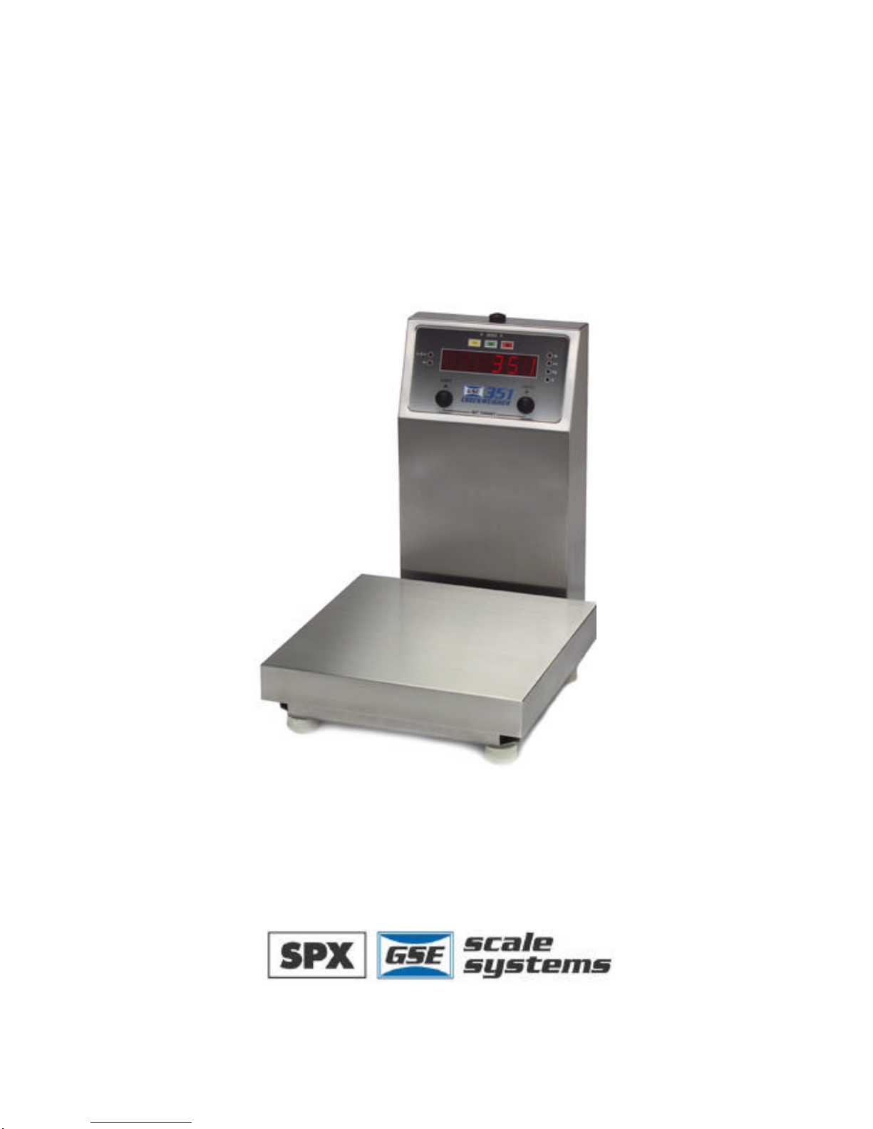
GSE 351
Checkweigher
Reference Manual 1.0
Page 2

ii
GSE 351
Reference Manual 1.0
Page 3

GSE 351 Checkweigher Reference Manual
Copyright © 2000 GSE Scale Systems. All rights reserved.
Published by:
GSE Scale Systems
42860 Nine Mile Road
Novi, MI 48375
USA
Information in this Reference Manual is subject to change without
notice due to correction or enhancement. The information
described in this manual is solely the property of GSE. No part of
this manual may be reproduced or transmitted in any form or by
any means, electronic or mechanical, including photocopying and
recording and sold for any monetary figure without the express
written permission of GSE.
GSE Locations
GSE Scale Systems
42860 9 Mile Road
Novi, MI 48375
U.S.A.
Phone: (800) 755-7875
www.gse-inc.com
GSE Canada, Inc.
617 East Lake Road
Airdrie, Alberta Canada T4B 2B8
Phone:(403) 948-9921
Fax: (403) 948-1449
Page 4

Page 5

i
Contents
CHAPTER 1: Introduction........................................................................................................1
CONVENTIONS AND SYMBOLS.............................................................................................1
DISPLAY..................................................................................................................................2
LED Display....................................................................................................................2
Annunciators...................................................................................................................2
KEYPAD ..................................................................................................................................3
WEIGH MODE FUNCTIONS...................................................................................................3
SECONDARY FUNCTIONS.......................................................................................................4
SPECIFICATIONS.....................................................................................................................5
Performance ..................................................................................................................5
Electrical.......................................................................................................................5
Operation.......................................................................................................................5
Communication.............................................................................................................5
display...........................................................................................................................5
Enclosure.......................................................................................................................5
Options..........................................................................................................................5
Platform.........................................................................................................................5
CHAPTER 2: Installation ..........................................................................................................7
BENCHTOP MOUNTING.........................................................................................................7
WIRING...................................................................................................................................9
Power Connection..........................................................................................................9
DC Power Connection..................................................................................................9
Serial Port Connection..................................................................................................9
Remote Key Connection..............................................................................................11
Load cell connection....................................................................................................12
CHAPTER 3: Getting Started.................................................................................................13
DEFAULT SETUP ..................................................................................................................13
OPERATION...........................................................................................................................13
Entering a Target Value..............................................................................................14
Entering Tolerances.....................................................................................................17
Status Indication...........................................................................................................18
Counting........................................................................................................................18
Printing out a Ticket....................................................................................................19
CHAPTER 4: Configuration....................................................................................................21
SETUP MODE........................................................................................................................21
Selection Parameters...................................................................................................23
Key-In Parameters........................................................................................................24
PARAMETER MAP ................................................................................................................25
PARAMETER MAP DETAILS................................................................................................27
CUSTOM TRANSMIT SETUP ................................................................................................37
Elements Of A Custom Transmit................................................................................37
Parameters...................................................................................................................38
Page 6

ii
ACSII Text ..................................................................................................................38
Control Codes .............................................................................................................38
Writing A Custom Transmit ASCII Text File...........................................................38
Accessing Setup and Clearing Existing Custom Transmit....................................39
Entering ASCII Text.....................................................................................................39
Entering ASCII Control Codes..................................................................................39
Parameter Selection Numbers....................................................................................41
Exiting Setup Mode And Saving Changes................................................................43
TIME/DATE OPERATION.....................................................................................................43
REMOTE KEY O PERATION..................................................................................................45
REMOTE SERIAL O PERATION.............................................................................................46
Display Capture Utility...............................................................................................46
Example #1.................................................................................................................47
Example #2.................................................................................................................47
TARGET AND TOLERANCE SETUP .....................................................................................47
RS-485 MULTI-DROP NETWORK SETUP AND OPERATION..........................................48
Setup ...............................................................................................................................48
Operation.......................................................................................................................49
Network Protocol .........................................................................................................49
CHAPTER 5: Calibration........................................................................................................51
SETUP MODE CALIBRATION ..............................................................................................51
FAST CALIBRATION.............................................................................................................51
PERFORMING CALIBRATION..............................................................................................52
Select and Calibration Method and Establish Zero ...............................................52
First Zero?...................................................................................................................52
Last Zero .....................................................................................................................53
False Zero....................................................................................................................54
Only Zero ....................................................................................................................55
Reset Calibration.........................................................................................................56
Establishing A Span.....................................................................................................58
Exiting Calibration......................................................................................................58
CHAPTER 6: Legal For Trade................................................................................................61
NTEP REQUIREMENTS.......................................................................................................61
OIML REQUIREMENTS.......................................................................................................62
OTHER REQUIREMENTS......................................................................................................62
SEALING AND AUDIT TRAILS............................................................................................62
Physical Seal.................................................................................................................63
Audit Trails....................................................................................................................64
OIML Audit Trail..........................................................................................................64
Calibration Audit Trail................................................................................................65
Setup Audit Trail.........................................................................................................65
Viewing Audit Trail Parameters .................................................................................65
CHAPTER 7: Model 351 Options...........................................................................................67
RS- 485 NETWORKING.......................................................................................................67
Network Connections...................................................................................................68
Page 7

iii
Half-Duplex (2-wire)..................................................................................................69
Full Duplex (4-wire)...................................................................................................69
Both Half Duplex and Full Duplex.............................................................................69
20 MA CURRENT LOOP O PERATION.................................................................................72
Installation....................................................................................................................72
Bi-Directional...............................................................................................................72
Baud................................................................................................................................72
Active/Passive...............................................................................................................72
Isolation .........................................................................................................................73
Max Voltage..................................................................................................................73
Connections...................................................................................................................73
Cable..............................................................................................................................73
Connected Devices.......................................................................................................74
CHAPTER 8: Troubleshooting................................................................................................75
ERROR MESSAGES...............................................................................................................75
Operational Errors.......................................................................................................75
Setup Mode Errors.......................................................................................................76
Hardware Errors..........................................................................................................77
Calibration Errors........................................................................................................77
Communication Errors................................................................................................78
Miscellaneous Errors...................................................................................................78
V IEWING SETUP ...................................................................................................................78
INFORMATION MODE PARAMETERS.................................................................................79
A/D CALIBRATION PROCEDURE .......................................................................................81
Page 8

Page 9

1
CHAPTER 1: INTRODUCTION
Thank you for selecting the GSE Model 351 Checkweigher. The Model 351
continues the GSE tradition of Excellence in Weighing Technology. A
properly installed and maintained Model 351 will provide many years of
reliable, accurate performance.
The chapters of this manual focus on various aspects of the indicator:
Chapter 1: Introduction Basic operating information.
Chapter 2: Installation Installation instructions.
Chapter 3: Getting Started Enter a target and tolerance limits.
Chapter 4: Configuration Access the Setup Mode and configure the
indicator to a specific application.
Chapter 5: Calibration Access the Calibration Mode and match the
load sensing device to the indicator.
Chapter 6: Legal-for-Trade Legal-for-trade information.
Chapter 7: Options Available options.
Chapter 8: Troubleshooting Troubleshooting help and error messages.
CONVENTIONS AND S YMBOLS
[ZERO] A keypress appears in bold with brackets.
[PRINT]+[UNITS] ‘+’ indicates keys pressed simultaneously.
Setup Display prompts are bold italic.
Setup ~ Enter ~ =Cal! ‘~’ indicates multi-part display prompts.
Fast ~ Cal! Display prompts can appear in sequence.
First ~ 0? ~ 0.00
! Indicates important considerations.
i Provides additional information.
Page 10
Model 351 Checkweigher
2
DISPLAY
The M351 displays alpha-numeric data, but due to the nature of 7-segment
LEDs and the limitation of six digits, some information is abbreviated.
All segments and annunciators are illuminated for a brief display test upon
power up. The current gross weight is then displayed in default units.
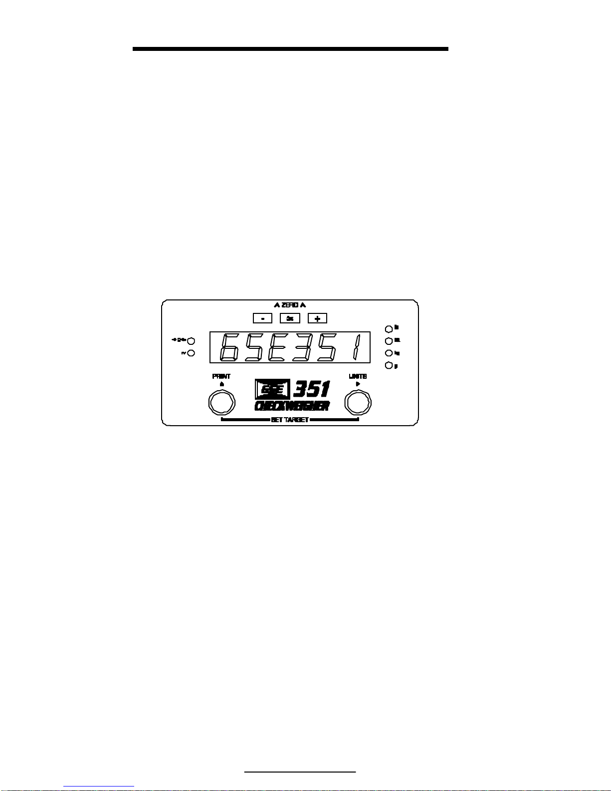
LED DISPLAY
The LED display is a six digit, 7-segment bright red LED screen with
9 annunciators to show weight and status information. The – (Low
Limit) = Yellow, + (High Limit) = Red and OK (Within tolerance) =
Green. Also there are annunciators for 5 units of measure.
Figure 1: Model 351 LED Display
ANNUNCIATORS
Annunciators provide mode and status information. When illuminated, they
indicate the following conditions:
- (Yellow) Current weight is under the low limit tolerance.
OK (Green) Current weight is within tolerance.
+ (Red) Current weight is over the high limit tolerance.
ÚÚ 0ÙÙ Displayed weight is at center-of-zero (± ¼ display
graduation).
~ Scale is in motion. Motion inhibited transmits will be delayed
until motion ceases.
lb The displayed value is represented in pounds.
oz The displayed value is represented in ounces
Page 11
3
kg The displayed value is represented in kilograms
g The displayed value is represented in grams
lb oz When both the lb and oz annunicators are lit the displayed
value is represented in lb oz.
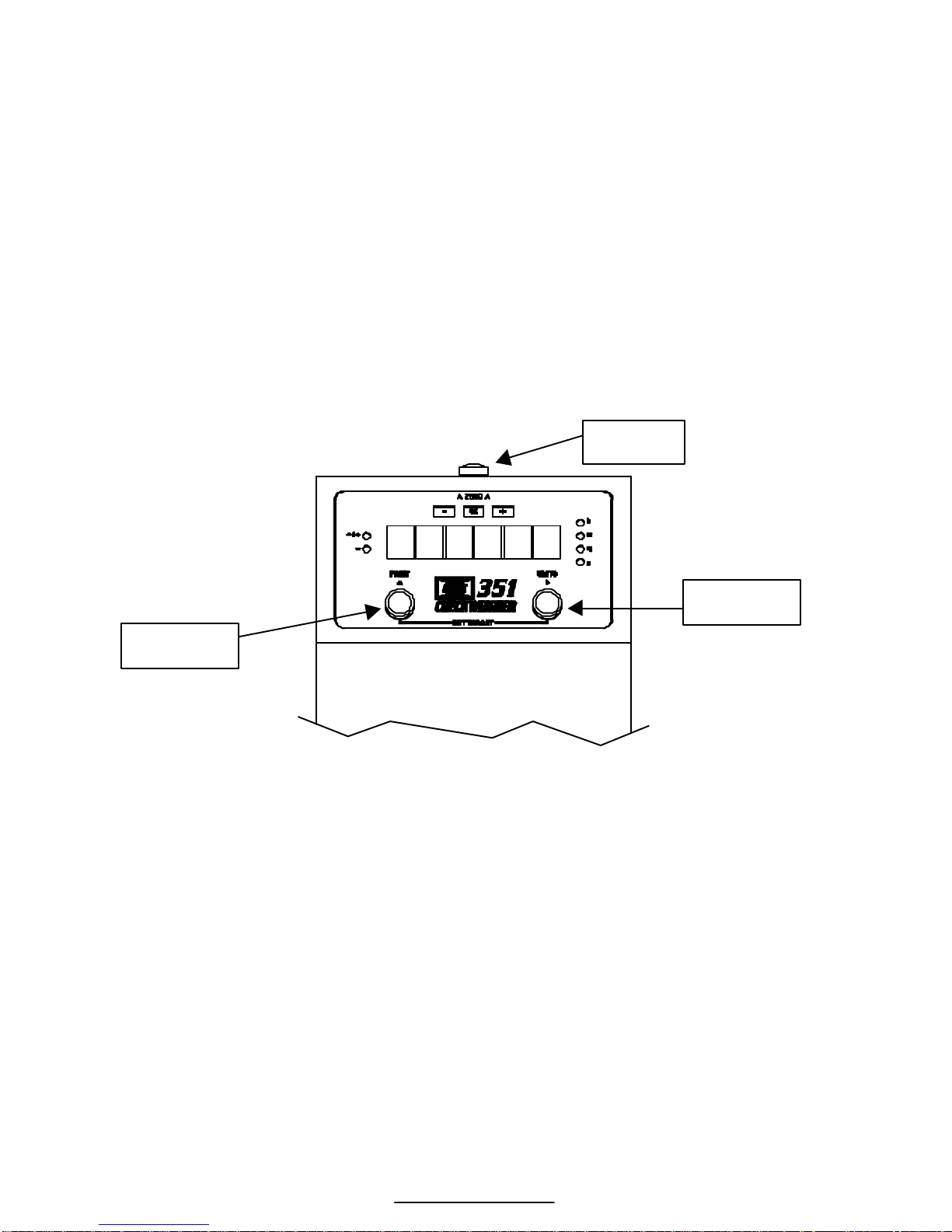
KEYPAD
Three rigid IP67 sealed buttons are used for operator input. Each key is
assigned two distinct functions. Various key combinations are also used.
Each key has secondary functions, allowing an operator to enter target
values, perform piece samples, access setup parameters, etc.
Figure 2: 351 Function Keys
WEIGH MODE FUNCTIONS
The Model 351 Checkweigher has 3 primary Weigh Mode functions:
[ZERO] Performs a gross zero and selects the gross mode.
[PRINT] Initiates data transmission out the communication port.
[UNITS] Toggles the units of measure between ‘lb’, ‘kg’, ‘oz’, ‘lb’
‘oz’ and ‘grams’.
ZERO
UNITS
PRINT
Page 12

Model 351 Checkweigher
4
SECONDARY FUNCTIONS
The Model 351 keys perform different functions in the weigh mode, the
setup mode and the calibration mode. Secondary functions for each key
will allow additional tasks to be performed.
Table 1: Key Functions
Key Press Weigh Mode Count Mode Setup Mode
[ZERO]
Performs a gross
zero function
and/or clears an
entry in progress.
Hold this key on
power-up to turn
on the display
regardless of P420.
Performs a
quantity zero
function and/or
clears an entry in
progress. From
the sample mode,
returns to the
gross weigh mode.
Exits the Setup Mode
and/or answers “NO”
to query prompts
and/or clears an entry
in progress. Also acts
as a [SELECT] key.
[PRINT / p ]
Performs a print
function and/or
‘scrolls’ through
digits during
target or limit
entry.
Performs a print
function and/or
‘scrolls’ through
digits during
target or limit
entry.
‘Scrolls’ through
digits during data
entry.
[UNITS / u ]
Toggles between
‘lb’, ‘kg’, grams,
ounces and lb oz
and/or advances
cursor to next
entry position.
Toggles through
standard sample
sizes and/or begins
a new sample
entry.
Advances cursor to
next entry position
and/or cycles
prompts.
[PRINT]+
[UNITS]
Access target
entry mode.
Access target
entry mode.
Acts as an [ENTER]
keypress.
[ZERO]+
[PRINT]
Decrements the
right-most digit
during data
entry.
Decrements the
right-most digit
during sample
entry.
Decrements the rightmost digit during
sample entry.
[ZERO] +
[UNITS}
Backspace –
erases right-most
digit during data
entry.
Backspace – erases
right-most digit
during data entry.
Backspace – erases
right-most digit
during data entry.
[ZERO]+[PRINT]
+[UNITS]
Access the setup
mode.
Access the setup
mode.
Exit the setup mode.
Page 13

5
SPECIFICATIONS
PERFORMANCE
Full Scale (F.S.) Selectable 0 to 999,990
Resolution 20-bit A/D converter, 100,000d displayed,
+/- 500,000d internal
A/D Conversion 60 Hz
Zero Track Off – 10d
Zero Range 0-100% of F.S. span
Operating Temperature -10 C to +40 C
Warranty 2 year
Units of Measure kg, lb, grams, lb oz, oz
ELECTRICAL
Power Requirement 90-250 VAC / 12-36 VDC
Excitation Voltage 10 VDC
Signal Input Sensitivity 0.1 – 20 mV/V
OPERATION
Modes Selectable modes such as target, count and HI/LO limits.
Remote Input 1 momentary contact closure (100ms minimum)
Keys 3 buttons for easy of setup and operation
COMMUNICATION
Port 1 RS232 bi-directional serial port. RS485 or 20 mA optional
Data Output String Twenty one (21) selectable fixed-format transmissions available,
1 custom format (programmable via RS232)
Protocol Selectable
Baud Rate 150-9600 bps
DISPLAY
LED Bright RED 6-digit weight display, 0.8” (22mm) height with
9 LED annunciators for operational status: Zero indication,
Motion, High, low, accept and units of operation
ENCLOSURE
With Column Both the enclosure and column are NEMA 4X (IP 66) stainless
steel. Durable enough for washdown environments and cleaning
agents
OPTIONS
RS485 Module Isolated multi-drop with 251 devices max, half or full duplex up to
4000 feet, 9600K bps max
20mA Current Loop Isolated TX-Active or Passive, RX-Passive, 9600 bps max,
12VDC, 1000 feet
Stainless Steel Load Cell includes a stainless steel load cell shield
PLATFORM
10 x10 and 12 x 12 Equipped with Shock – Stopper overload and under-load protection.
Open platform design for ease of cleaning
Page 14

Page 15
7
CHAPTER 2: INSTALLATION
This chapter contains information necessary for proper installation of the
Model 351 Checkweigher. Please review these instructions before installing
your scale.
High voltages may exist within the enclosure. To prevent the risk of
electrical shock, ALWAYS unplug the Model 351 when opening the
enclosure. Installation and servicing of the Model 351 should be performed
only by authorized and qualified service personnel.
For information on installing options, see Chapter 7: Model 351 Options. For
NTEP and OIML details, see Chapter 6: Legal For Trade
!!
IMPORTANT! The Model 351 does not include an on/off switch and
therefore must be installed near a power outlet socket that is easily
accessible and in keeping with UL/CSA Safety Standards.
INFORMATION IMPORTANT! Prendre note que les contrôleurs de
serie 351 ne sont pas munis d'interrupteurs "Marche / Arrêt". Par
conséquent, il devront être installés près d'une source d'alimentation secteur
accessible pour demeurer sous les exigences des normes de sécurité
UL/CSA.
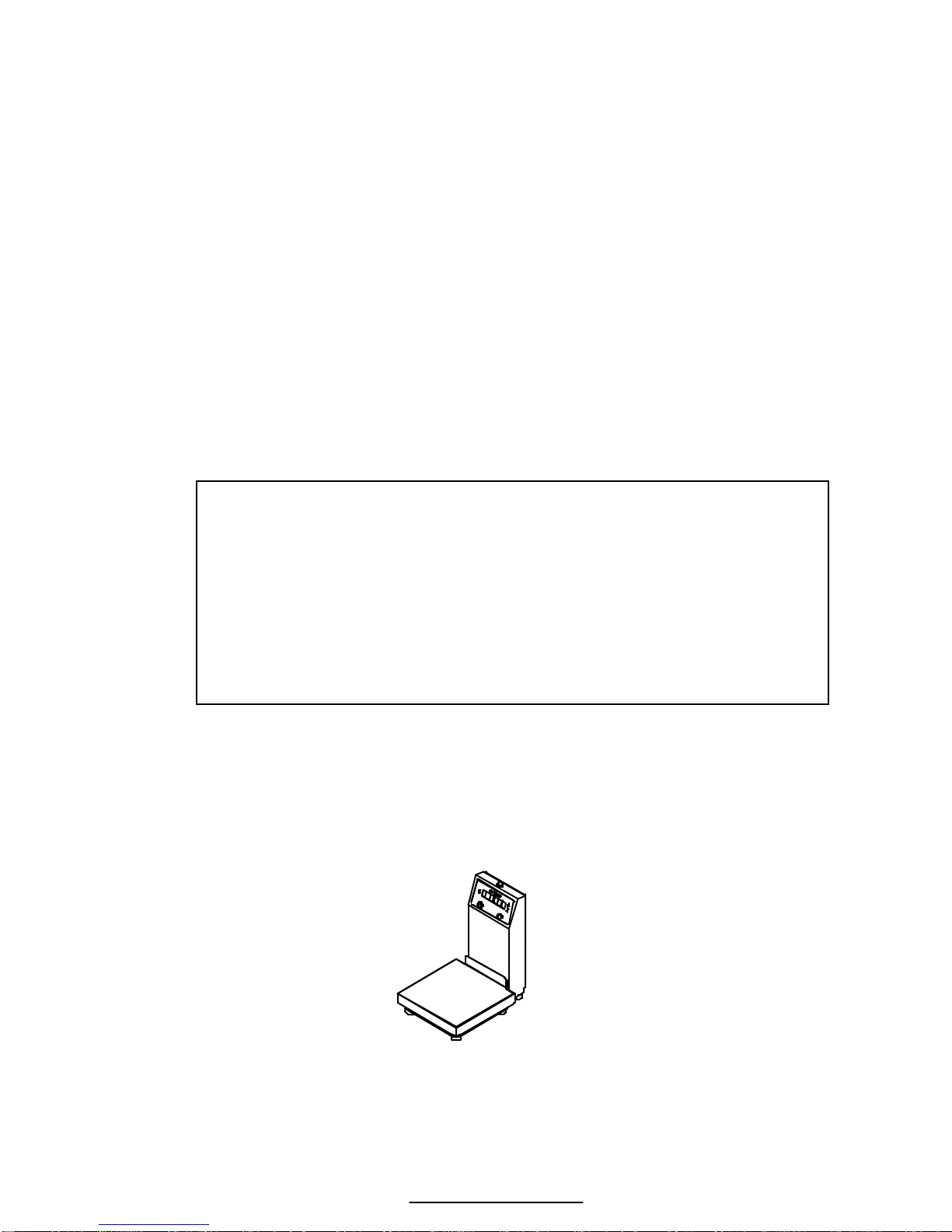
BENCHTOP MOUNTING
The Model 351 enclosure and column meet NEMA 4X type specifications.
When choosing a mounting location, make sure the unit is level (a level
bubble is located under the platform shroud) and free from obstructions.
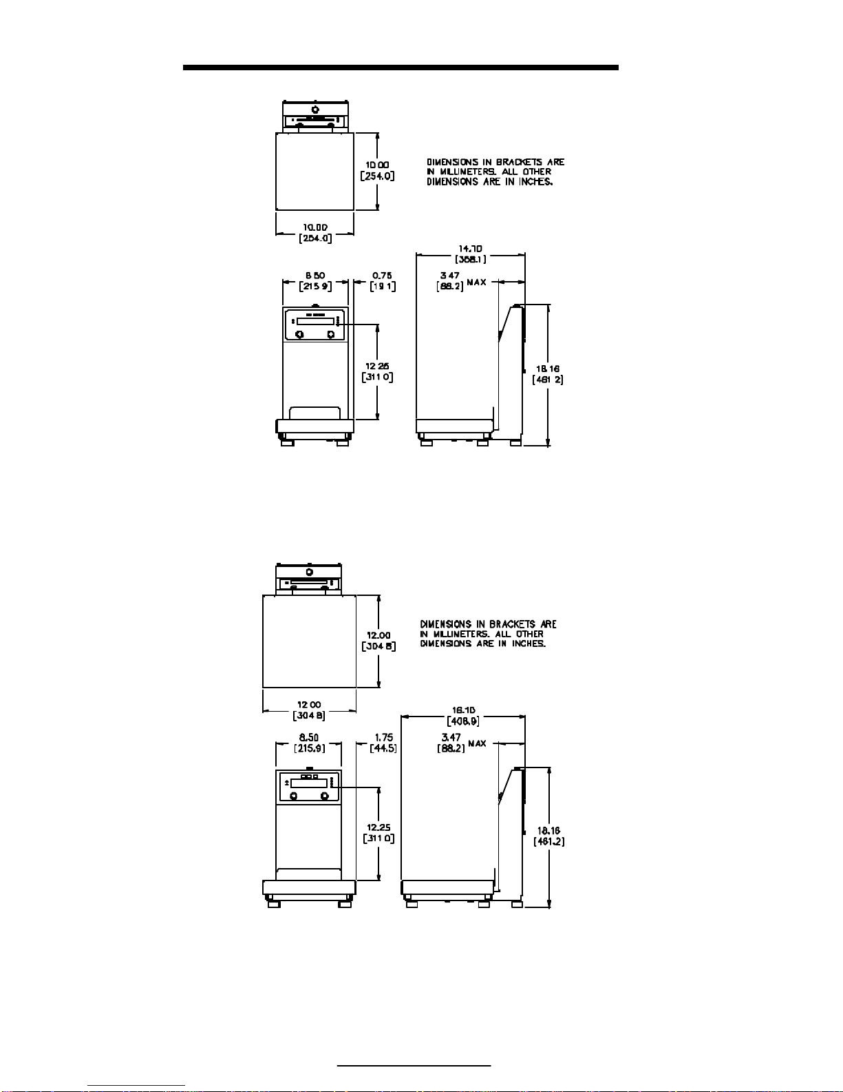
Figure 3: Model 351 with 10x10 platform
Page 16
Model 351 Checkweigher
8
Figure 4: Model 351 with 10x10 Platform Dimensions
Figure 5: Model 351 with 12x12 Platform Dimensions
Page 17
Chapter 2: Installation
9
WIRING
POWER CONNECTION
There are two ways to power the Model 351, with a 90-250 Volt line cord
(U.S. Style standard) or with a 12-36 VDC external source.
i
The Model 351 does not include an on/off switch. In keeping with
UL/CSA Safety Standards it must be installed near an easily accessible
power outlet.
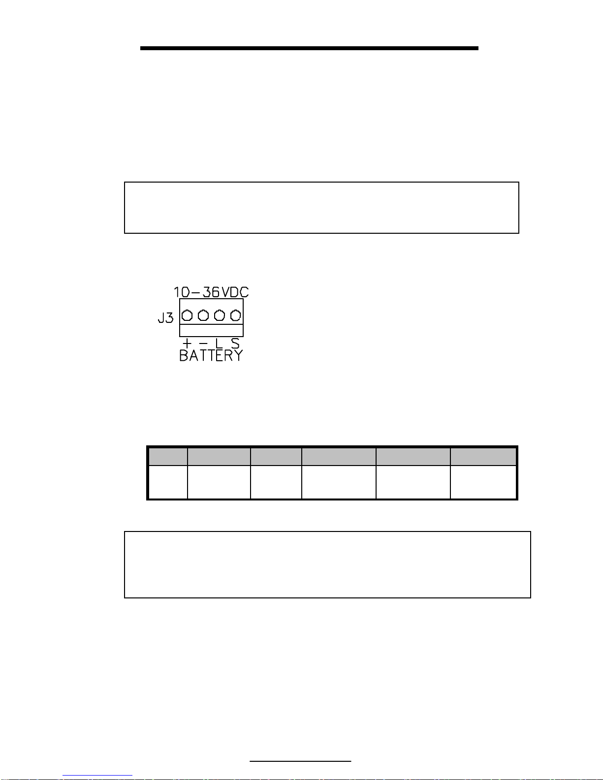
DC POWER CONNECTION
Wire the DC supply to the J3 connector
on the Model 351 main board. Do not
connect pins 3 or 4. The mating
connector can be purchased from a local
electronics supplier. Recommended
connectors are GSE PN: 26-20-3365 (24
AWG) or GSE PN: 26-20-3366 (22
AWG) / AMP PN: 640441-3 (24 AWG)
or AMP PN: 640440-3 (22 AWG).
Connector cover GSE PN: 26-20-3389
or AMP PN: 643075-3.
!!
CAUTION: Do not apply AC power through the line cord when a DC
source is attached. When AC is supplied, the voltage at J3 is 24 VDC.
This voltage can damage batteries attached to J3 unless a protection
diode is used to prevent backfeeding.
SERIAL PORT CONNECTION
Before connecting to the serial port, consideration should be given to the
communication protocol and to any remote key requirements. For
information on remote key operation, refer to Remote Key Operation on page
11. Use Table 2 to determine proper wiring to the communication port.
Figure 6: DC Power
Connector
Pin 1 Pin 2 Pin 3 Pin 4 Range
DC + - Do not use Do not use 12 - 36 VDC
Page 18
Model 351 Checkweigher
10
Communication connections are made with a pigtailed cable through a strain
relief. The cable should be 20 to 28 AWG with a braided or foil shield for
either model type. The maximum recommended cable length is 50 feet (15
meters). However, much longer connections are possible if using a properly
shielded, low-capacitance cable.
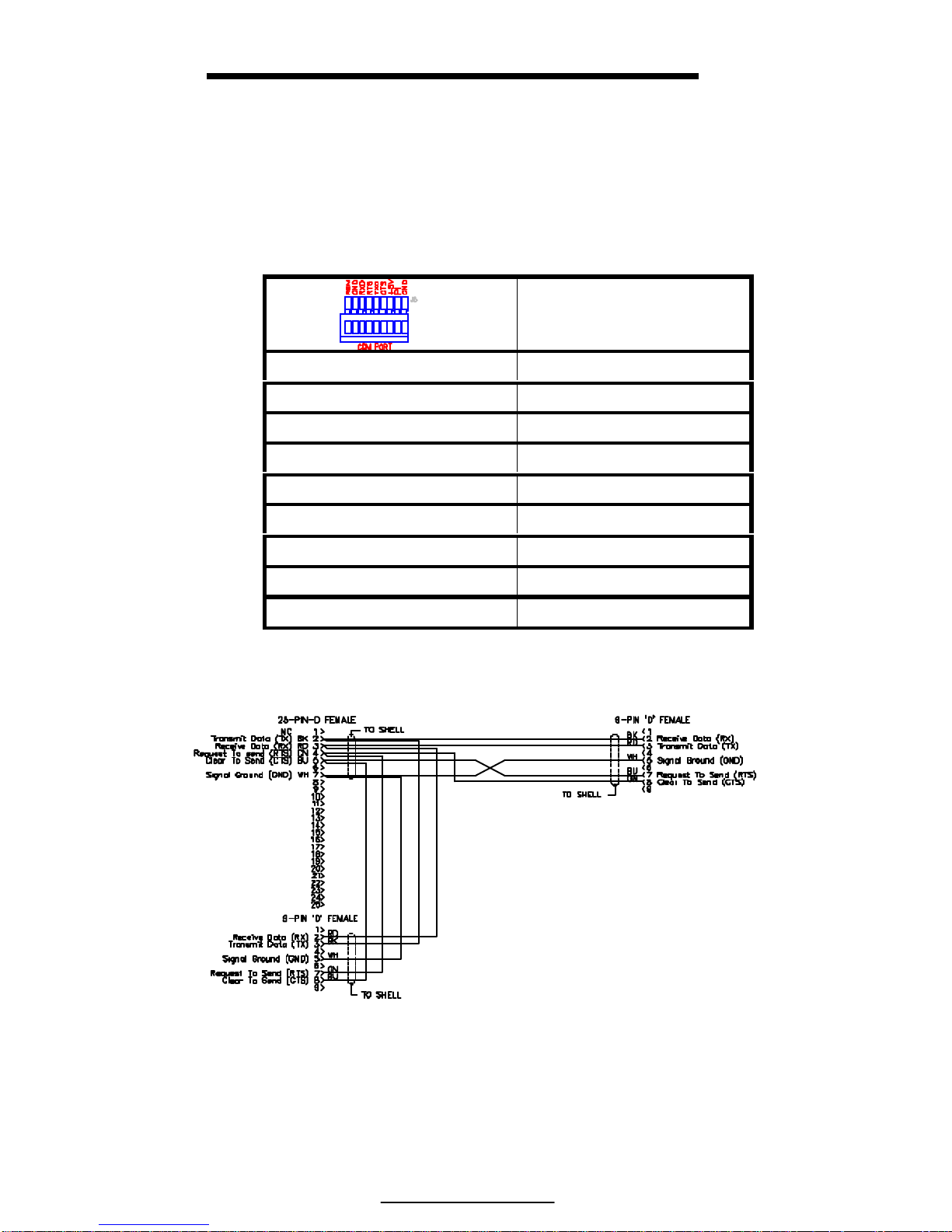
Table 2: Serial Port Connections
Description
REM Remote Key
GND Digital Ground
RXD Receive
RTS Request-to-Send
TXD Transmit
CTS Clear-to-Send
+5V +5 VDC
PI Do Not Connect
GND Digital Ground
Figure 7: : GSE Serial Cable, Part Number 22-30-29752
Page 19

Chapter 2: Installation
11
A communication cable (P/N: 22-30-29752) may be purchased from
GSE
REMOTE KEY CONNECTION
A remote key may be connected to the Model 351 communication port to
provide remote activation of print or zero functions.
The connection for the remote key input is between pin 1 and pin 2. A twoconductor shielded cable between 28 and 20 AWG is recommended. The
input requires a contact closure from a push-button switch, a ‘dry’ relay
contact, a photo-eye, and a proximity sensor or other such device. A closure
initiates the operation specified at P800.
!!
Do not apply an external voltage to remote key terminals! Only a
contact closure is required to activate the remote key input.
The open circuit voltage across the remote key pins is +5 VDC. A closed
switch will conduct about 0.25 mA. Therefore, a low-voltage switch with
gold-plated contacts is recommended. A Mercury-wetted switch will also
work well. A minimum contact duration of 100 ms is required. Once
invoked, the selected remote key operation will not repeat until the contact is
released and closed again.
Figure 8: Remote Key Connection
Page 20
Model 351 Checkweigher
12
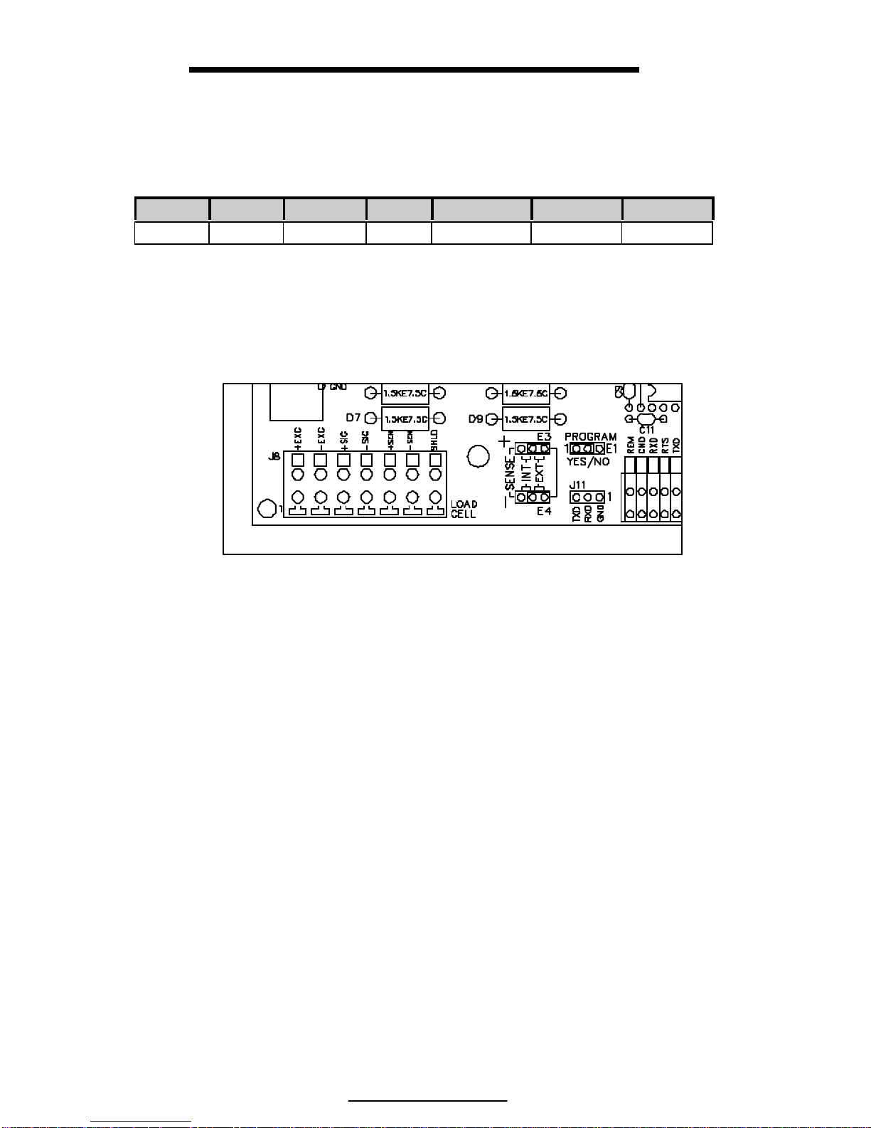
LOAD CELL CONNECTION
The Model 351 will come equipped with either an aluminum or stainless
steel load cell. The load cells used have 7 wires.
+ EX - EX + SIG - SIG + SENSE - SENSE SHIELD
Green Black White Red Orange Blue Wire
When replacing a load cell or main board, be sure to use the proper
connections. The load cell is connected to J8 on the main board. Make sure
the sense jumpers E3 and E4 are set to external (EXT).
Figure 9: Model 351 Load Cell Connector and Sense Jumpers
Page 21
13
CHAPTER 3: GETTING STARTED
DEFAULT S ETUP
If a factory default is performed at parameter 65001, the target values and
tolerances will have default values. Below is the default values and
checkeweighing method. These are also set when the unit is delivered from
the factory.
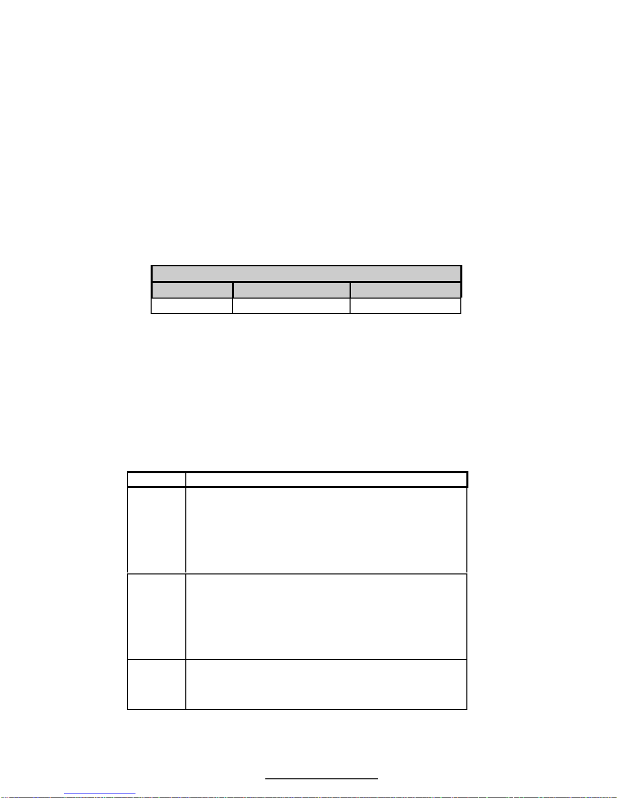
Checkweighing Method - Checb
TARGET LO TOLERANCE HI TOLERANCE
5.00 1.00 1.00
OPERATION
The Model 351 Checkweigher offers easy of operation. Entering target and
tolerance values is simply done by pressing [PRINT] + [UNITS]. Below is a
table with the different checkweighing methods available. The operation of
the Model 351 depends on the method chosen. Refer to Table 3 for
examples of the available methods.
Table 3: Checkweighing Methods
Choice Description
Checb
The target is varied by the Hi/Lo limits
Example: Target = 20, Hi limit = .8, Lo
Limit= .5
20 + .8 = 20.8 and 20 - .5 = 19.5
Accept Window = 19.5 to 20.8
ChecP
Hi/lo limits are used as a percentage deviation.
Example: Target = 20, Hi Limit = 5, Lo
Limit = 5
20 + 5% = 21 and 20 – 5% = 19
Accept Window = 19 to 21
ChecA
The values are absolute, Target is not used.
Example: TargH = 21.3, TargL = 19.8
Accept Window = 19.8 to 21.3
Page 22

Model 351 Checkweigher
14
ENTERING A TARGET VALUE
Entering a target depends on the checkweighing method chosen and the
access setting. Refer to Table 4 for a comparison of the available methods
and access settings.
Table 4: Entering Targets and Tolerances
Checkweighing
Method (P5100)
Access Setting
(P5020)
Weigh Mode
Disbl – This choice
assures the target and
tolerances cannot be
changed from the
weigh mode.
When the [PRINT] + [UNITS] keys
are pressed the Target, lo Limit and
Hi Limit values are shown for one
second each but not changeable
Targ – This choice
allows only the target
value to be changed
in the weigh mode.
When the [PRINT] + [UNITS] keys
are pressed only the Target can be
changed. HI/LO limits can be viewed
by pressing the [UNITS] key during
target entry mode.
Checkb
All – This choice
allows the target and
tolerance limits to be
changed from the
weigh mode.
Press [PRINT] + [UNITS] to view
the Target first. Either accept the
weight on the scale or scroll in a
target. Press [PRINT] + [UNITS]
again for the LO limit and [PRINT]
+ [UNITS] for the HI limit.
Disbl – This choice
assures the target and
tolerances cannot be
changed from the
weigh mode.
When the [PRINT] + [UNITS] keys
are pressed the Target, lo Limit and
Hi Limit values are shown for one
second each but not changeable
Targ – This choice
allows only the target
value to be changed
in the weigh mode.
When the [PRINT] + [UNITS] keys
are pressed only the Target can be
changed. HI/LO limits can be viewed
by pressing the [UNITS] key during
target entry mode.
Checkp
All – This choice
allows the target and
tolerance limits to be
changed from the
weigh mode
Press [PRINT] + [UNITS] to view
the Target first. Either accept the
weight on the scale or scroll in a
target. Press [PRINT] + [UNITS]
again for the LO limit and [PRINT]
+ [UNITS] for the HI limit.
Page 23

Chapter 3: Getting Started
15
Checkweighing
Method (P5100)
Access Setting
(P5020)
Weigh Mode
Disbl – This choice
assures the absolute
values cannot be
changed from the
weigh mode.
When the [PRINT] + [UNITS] keys
are pressed the TargeL and targH
values are shown for one second each
but not changeable
Targ – This choice
allows the absolute
low target value and
the absolute high
target to be changed
in the weigh mode.
When the [PRINT] + [UNITS] keys
are pressed targL will be displayed.
Press [PRINT] + [UNITS] again and
targH will be displayed.
CheckA
All – This choice
allows the absolute
low target value and
the absolute high
target to be changed
in the weigh mode.
When the [PRINT] + [UNITS] keys
are pressed targL will be displayed.
Press [PRINT] + [UNITS] again and
targH will be displayed.
EXAMPLE 1: the checkweighing method is set to checp (percentage) and
the access setting is set to targ (Target).
To set a target of 6.5 from the weigh mode:
1. Press [PRINT] + [UNITS]
Targ1 ~ 5.00
2. Press the [PRINT] key until 6 is displayed
6
3. Press the [UNITS] key to move over a character
6 .
4. Press the [UNITS] key again to accept the .
6.
5. Press the [PRINT] key until 5 is displayed
6.5
6. Press the [PRINT] + [UNITS] to accept the entry
Targ1 ~ 6.50
7. Press the [PRINT] + [UNITS] to exit to the weigh mode
0.00
Page 24

Model 351 Checkweigher
16
EXAMPLE 2: enter a target with an acceptable weight on the scale. The
access setting is set to targ (Target).
To set a target of 2.10 lbs with a known weight:
1. Press [PRINT] + [UNITS] with the weight on the scale
Targ1 ~ 5.00
2. Press [PRINT] + [UNITS]. NOTE: The [ZERO] key may be pressed to
exit out of the entry process.
Accept ~ 2.10
3. Press the [PRINT] + [UNITS] to accept the target
2.10
EXAMPLE 3: the checkweighing method is set to checA (absolute) and the
access setting is set to All (Hi/Lo limits).
To set the low target to 4.5 and the high target to 5.8 from the weigh
mode:
1. Press [PRINT] + [UNITS]
TargL ~ 0.50
2. Press the [PRINT] key until 4 is displayed
4
3. Press the [UNITS] key to move over a character
4 .
4. Press the [UNITS] key again to accept the .
4.
5. Press the [PRINT] key until 5 is displayed
4.5
6. Press [PRINT] + [UNITS] to accept the entry
TargL ~ 4.50
7. Press [PRINT] + [UNITS] to show the high target
TargH ~ 1.50
8. Press the [PRINT] key until 5 is displayed
5
9. Press the [UNITS] key to move over a character
5 .
10. Press the [UNITS] key again to accept the .
5.
11. Press the [PRINT] key until 8 is displayed
5.8
Page 25

Chapter 3: Getting Started
17
12. Press the [PRINT] + [UNITS] to accept the high target value
0.00
ENTERING TOLERANCES
Tolerances are the bases for the acceptance window (OK). Checkb
(deviation) and Checkp (percentage) use tolerances and the target to
determine the accepted target. Refer to Table 3 for more details. Check A
operates differently by using two values and anything in between those
values is acceptable.
For Example, the checkweighing method is set to checb (deviation) and the
access setting is set to ALL (Target and Tolerances).
To set a target of 6.0, low limit of .5 and high limit of .6 from the weigh
mode (Acceptance Window 5.5 – 6.6):
Press [PRINT] + [UNITS]
Targ1 ~ 5.00
1. Press the [PRINT] key until 6 is displayed
6
2. Press [PRINT] + [UNITS] to accept the target
Targ1 ~ 6.00
3. Press [PRINT] + [UNITS] to display the Lo tolerance
1.00
4. Press the [PRINT] key once to display the .
.
5. Press [UNITS] to move the cursor. Press [UNITS] until 5 is displayed
.5
6. Press [PRINT] + [UNITS] to accept the Lo tolerance entry
Lo ~ 0.50
7. Press [PRINT] + [UNITS] to display the Hi tolerance
1.00
8. Press the [PRINT] key once to display the .
.
9. Press [UNITS] to move the cursor. Press [UNITS] until 6 is displayed
.6
10. Print [PRINT] + [UNITS] to accept the Hi tolerance entry
Hi ~ 0.60
11. Press [PRINT] + [UNITS] to accept the values and exit to the weigh
mode
0.00
Page 26
Model 351 Checkweigher
18
STATUS INDICATION
The status annunciators are located above the weight display. This allows
ease in checkweighing by simply looking at a status light. Only one light will
illuminate at a time. The status annunicators can be turned off (refer to page
37).
Below Target
-
Within Tolerance
OK
Above Target
+
COUNTING
It is possible to checkweigh in the counting mode. Parameter 179 must be
set for enabled (refer to page 29 for details). Operation is similar to the other
checkweigh methods. Target and tolerances may be entered or locked out.
EAMPLE 1: Doing A Sample
1. From the count mode press [UNITS]
Add 10
2. Add the sample pieces to the scale then press [PRINT] + [UNITS].
The OK status indicator should also be lit.
10
3. From the count mode press [UNITS]
EXAMPLE 2: To sample using selectable fixed counts:
1. From the Quantity Mode, press [UNITS]. The scale prompts to add 10
pieces.
Add ~ 10
2. Press [UNITS] to toggle sample amounts between 5, 10, 20, 50 and 100.
Add ~ 20
3. Add sample pieces to scale
Add ~ 20
4. Press [PRINT] + [UNITS] to sample and display the current quantity.
20.
Page 27
Chapter 3: Getting Started
19
EXAMPLE 3: To sample using variable counts (36 pieces):
1. From the Quantity Mode, press [UNITS]. The scale prompts to add 10
pieces.
Add ~ 10
2. Key in 36, then press [PRINT] + [UNITS] to sample as 36 pieces and
display the current quantity.
Add ~ 36
3. Add 36 pieces and press [PRINT] + [UNITS] to accept the quantity.
36.
PRINTING OUT A TICKET
Depending on the Comm Port configuration, printing a ticket is as simple as
pressing the [PRINT] key (refer to page 29).
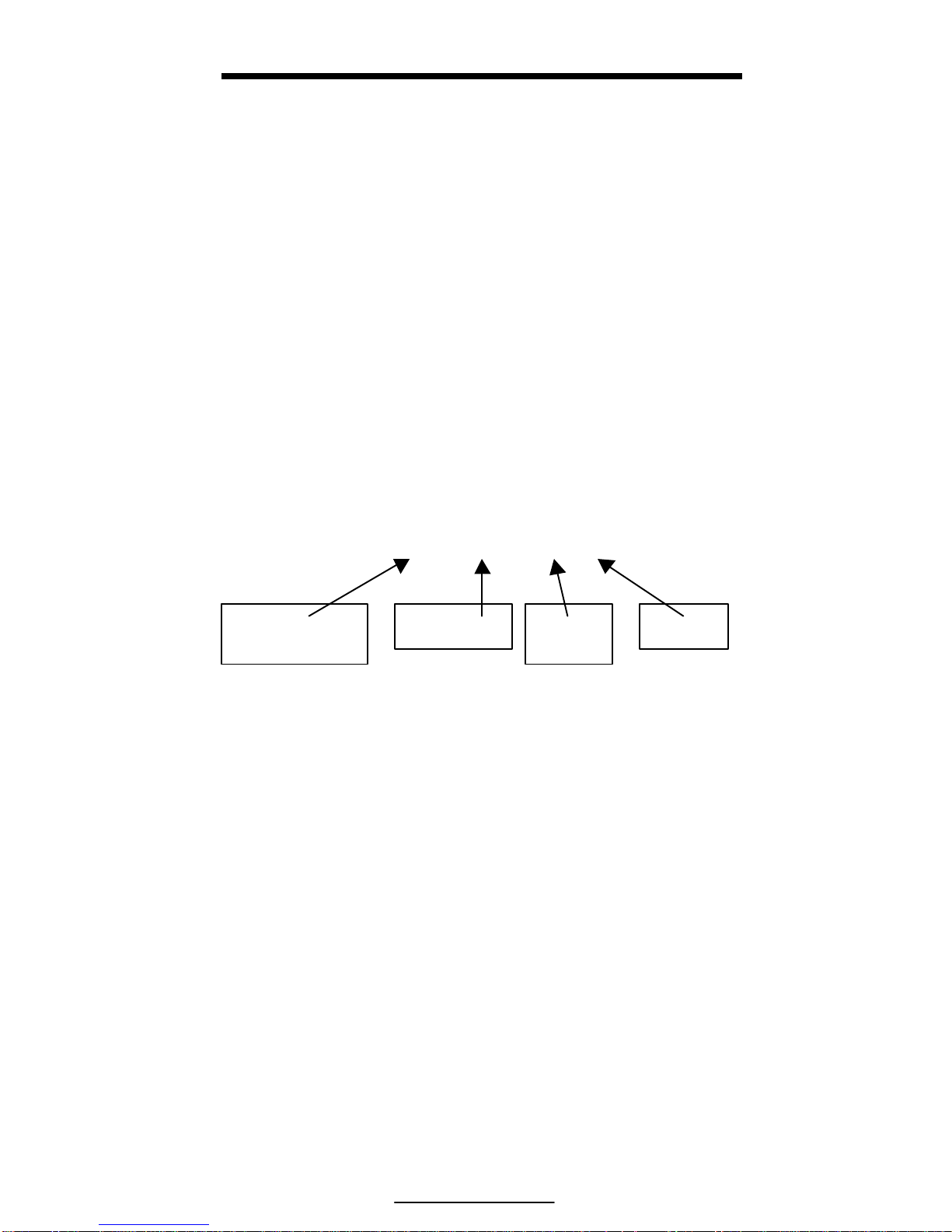
U -0.68 0.32 lb
Figure 10: Sample Print Out
Check Status
(Under)
Deviation
Gross
Weight
Unit
Page 28

Page 29

21
CHAPTER 4: CONFIGURATION
SETUP MODE
To prevent accidental changes to the indicator setup, a sequence of
keystrokes is used to gain access to the setup mode.
To access the setup mode:
1. From the weigh mode press [ZERO] + [PRINT] + [UNITS]
Setup ~ Enter Code
The following keystrokes must be made within five seconds or the indicator
will return to the weigh mode.
2. Press [PRINT]
P
3. Press [PRINT]
PP
4. Press [UNITS]
PPu
5. Press [UNITS]
PPuu
6. Press [PRINT] + [UNITS]
Chgs ~ Poss!
P110.— — ~ F.S.= ~ 50.00
To access setup in a view-only mode:
1. From the weigh mode press [ZERO] + [PRINT] + [UNITS]
Setup ~ Enter Code
2. Press [PRINT] + [UNITS]
No ~ Chgs
P110.— — ~ F.S.= ~ 50.00
Page 30

Model 351 Checkweigher
22
To advance to the next parameter:
4. Press [ZERO]
P111.09 ~ 1Grad ~ 0.01
5. Press [ZERO]
P112.05 ~ Ztrac ~ 0.5 d
6. Continue pressing [ZERO] to advance through all setup parameters.
To access the previous parameter:
1. Press [PRINT]
.
2. Press [ZERO]
P111.09 ~ 1Grad ~ 0.01
3. Repeat [PRINT] [ZERO] to back up one parameter
i
When accessing a parameter, the parameter number appears briefly. The
display then toggles between the parameter name and selection. Pressing
[UNITS] will again briefly display the parameter number.
To access a specific parameter from the setup mode (for example P150):
1. Press [PRINT] three times to select the first digit.
1
2. Press [UNITS] to advance to the next digit.
1.
3. Press [PRINT] six times to select the next digit.
15
4. Press [UNITS] to advance to the next digit.
15.
5. Press [PRINT] once to select the next digit.
150
6. Press [ZERO] to advance to the parameter.
P111.0 ~ Units ~ Lb
i
For information on accessing information parameters (P60000 – P65002),
see Information Mode Parameters on page 79.
Page 31

Chapter 4: Configuration
23
To exit the setup mode and save changes:
1. Press [ZERO] + [PRINT] + [UNITS] to begin exiting the setup mode.
Enter ~ =CAL!
2. Press [ZERO] to bypass the calibration mode.
Enter ~ =Stor
3. Press [PRINT] + [UNITS] to save setup changes.
Enter ~ =End
4. Press [PRINT] + [UNITS] to complete exit.
0.00
To exit the setup mode from the view-only mode:
1. Press [ZERO] + [PRINT] + [UNITS] to begin exiting the setup mode.
Enter ~ =End
2. Press [PRINT] + [UNITS] to complete exit.
0.00
To exit the setup mode without saving changes:
1. Press [ZERO] + [PRINT] + [UNITS] to begin exiting the setup mode.
Enter ~ =CAL!
2. Press [ZERO] to bypass the calibration mode.
Enter ~ =Stor
3. Press [ZERO] to exit without saving changes
Enter ~ =Undo
4. Press [PRINT] + [UNITS] to undo changes.
Enter ~ =End
5. Press [PRINT] + [UNITS] to complete exit.
0.00
SELECTION PARAMETERS
Selection parameters have a pre-defined list of choices to pick from. Each
choice is numbered and corresponds to a certain value. The choice number is
shown to the right of the decimal point within the parameter number.
Repeatedly pressing [PRINT] + [UNITS] while viewing a selection
parameter cycles through the available choices, or you can key in the choice
number.
Page 32

Model 351 Checkweigher
24
P 200.00
Indicates Parameter Parameter Number Choice Number
For example, parameter 200 is a selection parameter that holds the baud rate
for the serial. This is a selection parameter because a choice number between
00 and 06 must be used. Each choice number corresponds to a different baud
rate. To change the baud rate from the default value of 9600 to 4800,
perform the following steps from the Setup Mode.
To change the baud rate from the default value of 9600 to 4800:
1. Press 200 [ZERO].
P200.00 ~ Baud ~ 9600
2. Press [PRINT] + [UNITS] once.
P200.01 ~ Baud ~ 4800
KEY-IN PARAMETERS
Key-In Parameters are not limited to a list of choices, although there may be
upper and lower value limits. A Key-In Parameter requires that a numeric
value be entered using the front panel keys. Key-In Parameters are shown
with two hyphens after a decimal point within the parameter number.
P 110.--
Indicates Parameter Parameter Number Denotes “Key In”
To enter a Key-In Parameter:
1. Press [PRINT]. A decimal point is used to represent the entry position.
2. Press [PRINT] until the desired character appears.
3. Press [UNITS]. Another decimal point indicates the next entry position.
4. Repeat steps 1 and 2 until your desired entry value is shown.
5. Press [PRINT] + [UNITS] to enter your numerical value.
To setup a full target value of 10 lbs:
Page 33

Chapter 4: Configuration
25
1. Press 5101 [ZERO].
P5101.— — ~ TARG= ~ 5.00
2. Press [PRINT] three times to select the first digit.
1
3. Press [UNITS] to advance to the next digit.
1.
4. Press [PRINT] one time to select the next digit.
10
5. Press [PRINT] + [UNITS] to accept and enter the value.
P5101.— — ~ TARG= ~ 10.00
PARAMETER MAP
Table 5: Parameter Map
Parameter
Number
Display
Name
Default
Value
Valid Range/
Choices
Parameter
Description
Page
P110.-- F.S.= 10.00 .01 – 999,999
(Keyed In)
Full Scale 27
P111.09 1Grad .01 .00001 – 500
(24 Selections)
Count By 27
P112.05 Ztrac 0.5d Off - 20.0d
(200 Selections)
Zero Track
Aperture
27
P114.10 Stabl 1.0d Off – 20.0d
(200 Selections)
Stability
Window
27
P116.04 Filtr 1 Sec .065 – 8.00 Sec
(8 Selections)
Filter Setting 28
P117.01 Rate= 0.1 Sec 0.05 – 20.0 Sec
(201 Selections)
Display
Update
28
P118.12 Zrang 100% .01 – 100%
(13 Selections)
Zero Button
Range
28
P150.00 Units lb lb / kg
(Toggle)
Default
(Calibration)
Units
28
Page 34

Model 351 Checkweigher
26
Parameter
Number
Display
Name
Default
Value
Valid Range/
Choices
Parameter
Description
Page
P151.01 Unbut Enable Enable / Disable
(Toggle)
Units Button 28
P152.00 Lb Enable Enable / Disable
(Toggle)
Pounds
indication
28
P154.00 OZ Enable Enable / Disable
(Toggle)
Ounces
indication
29
P155.00 G Enable Enable / Disable
(Toggle)
Grams
indication
29
P156.00 Lb_OZ Enable Enable / Disable
(Toggle)
Pounds -
Ounces
indication
29
P179.00 Count Disable Enable / Disable
(Toggle)
Counting
Functions
29
P200.00 Baud 9600 150 – 9600
(7 Selections)
Comm Baud
Rate
29
P201.01 Data 8 Bits 7 – 8 Bits
(2 Selections)
Comm Data
Bits
29
P202.00 Par’y None None – Odd
(3 Selections)
Comm Parity 29
P203.00 Stop 1 Bit 1 – 2 Bits
(2 Selections)
Comm Stop
Bits
29
P204.02 HndSh Soft None – Both
(4 Selections)
Comm
Handshake
29
P210.01 Send Press Off – Cycle
(4 Selections)
Comm
Transmit
29
P212.01 Stabl Delay Off – Delay
(Toggle)
Comm Motion 30
P213.01 TrTyp --1-- 0 – 13
(Selection)
Print
Transmission
30
P250.00 RS485 Disable Enable / Disable
(Toggle)
Network
Option
34
P251.00 Addr Disable Disabled and 4 –
254 (Key In)
Network
Address
35
P410.-- Euro Disable Enable / Disable
9991/9990 (Key In)
OIML
Enforce
35
P420.01 Dsply On Off – Auto
(3 Selections)
Display
Function
35
P440.00 rStrc Disable Enable / Disable
(Toggle)
NTEP
Enforce
36
Page 35

Chapter 4: Configuration
27
Parameter
Number
Display
Name
Default
Value
Valid Range/
Choices
Parameter
Description
Page
P502.01 disbl
t-dAt
Disable Enable / Disable
(Toggle)
Time/Date
Function
36
P504.00 Style U.S.A U.S.A or
International
Time/Date
Function
36
P800.00 R-But None None – Zero
(3 Selections)
Remote
Button
Function
36
P1000.-- Cust.
Trans
-- -- Custom
Transmit
36
P5010.00 SPAnn Enable Enable / Disable
(Toggle)
Acceptance
Annunciators
37
P5020.00 Hi-Lo Disable Targ, Hi/LO, All
(Selectable)
Tolerance
Display
37
P5100.00 SetPt Check b None – Check A
(3 Selections)
Checkweigh
Operation
37
P5101.00 Target 5.00 .01 – 50.00
(Keyed In)
Target Entry 37
P5102.00 Lot 1.00 .01 – 50.00
(Keyed In)
Lo Tolerance
Entry
37
P5103.00 Hit 1.00 .01 – 50.00
(Keyed In)
Hi Tolerance
Entry
37
PARAMETER MAP DETAILS
P110 Full Scale Value (Key in)
Denotes the full scale capacity. This value should not exceed the rated
capacity of the weighing device.
P111 Division Size (Selection)
Indicates the count-by and decimal point.
P112 Zero Track Aperture (Selection)
Set in terms of number of divisions. Zero tracking eliminates small weight
deviations at or near zero. Weight deviations within the selected window that
have been stable for more than one second are tracked off, maintaining a
gross or net zero condition.
The sum of weight values zeroed with auto zero tracking and [ZERO] cannot
exceed the allowable zero range (P118).
P114 Stability (Selection)
Stability is defined as weight fluctuations within an aperture that can be
regarded as being a stable weight. Deviations outside this aperture are
considered motion, and the motion annunciator on the front panel will light
Page 36

Model 351 Checkweigher
28
accordingly. Once the scale settles within the stability aperture, the indicator
will wait one second before the indicator is considered stable.
Print operations configured as motion delayed (P114) will not send the
specified data until the weight reflects a stable reading as designated by this
setting.
P116 Filter (Selection)
Sets the indicator response time in terms of seconds. Filtering determines
how quickly the indicator will respond to changing input signals. A low filter
setting speeds the response, a higher filter setting will ‘dampen’ the
response.
Filtering is used to filter out weight fluctuations caused by outside sources,
such as vibrations or air currents.
P117 Rate (Selection)
Specifies how often the display is updated with new data. For example, if
0.05 is selected, the controller will write data to the display every time an
analog/digital conversion is made. Since the A/D converter updates every
0.05 sec, selections from 0.05 to 20.0 seconds are available. This parameter
also affects the transmission rate for continuous transmit. Actual
transmission intervals are dependent upon system setup.
P118 Zero Range (Selection)
Specifies how many divisions can be zeroed in terms of a percentage of full
scale (P110). The sum of weight values zeroed through the [ZERO] key and
auto zero tracking cannot exceed this range.
P150 Units (Toggle)
Set default units to ‘lb’, ‘kg’, ‘lb oz’, ‘grams’ or ‘oz’. The indicator must use
the default units during calibration procedures (see ). The default units are
the displayed units upon indicator power-up.
P151 Units Button (Toggle)
When enabled, this parameter will allow [UNITS] to toggle the units. When
disabled, the indicator will show only the calibration units as determined by
P150.
P152 Pounds (Toggle)
This parameter will allow the ‘lb’ units to be disabled individually. It is still
possible to have ‘lb’ as default calibration units.
P153 Kilograms (Toggle)
This parameter will allow the ‘kg’ (1000 g) units to be disabled individually.
It is still possible to have ‘kg’ as default calibration units.
Page 37

Chapter 4: Configuration
29
P154 Ounces (Toggle)
This parameter will allow the ‘oz’ units to be disabled individually. It is still
possible to have ‘oz’ as default calibration units.
P155 Grams (Toggle)
This parameter will allow the ‘g’ units to be disabled individually. It is still
possible to have ‘g’ as default calibration units.
P156 Lb oz (Toggle)
This parameter will allow the ‘lb oz’ units to be disabled individually. It is
still possible to have ‘lb oz’ as default calibration units.
P179 Count (Toggle)
When enabled, the counting mode becomes accessible. See page 18 for
details on counting.
P200 Baud (Selection)
Set the desired baud rate for the communication port.
P201 Data Bits (Toggle)
Select 7 or 8 data bits for the transmission.
P202 Parity (Selection)
Select Odd, Even or None for the transmission parity.
P203 Stop Bits (Toggle)
Select 1 or 2 stop bits for communication port transmissions.
P204 Comm Handshake (Selection)
Select from None, Software (Xon/Xoff), Hardware (CTS/RTS), or Both.
P210 Send (Selection)
Transmission Send options:
Choice Number
Selection
Name
Description
P210.00 Off All transmissions disabled.
P210.01 Press Sends transmission with [PRINT] key.
P210.02 Cont. Sends transmissions continuously.
P210.03 Cycle
Send single transmission after weight is
reached and motion ceases. Must return
display value below 0.1% of F.S. to reset for
next transmission.
Page 38

Model 351 Checkweigher
30
P212 Send Stability (Toggle)
Enabling Send Stability will delay any transmissions until a no-motion
condition exists.
P213 Transmit Selection (Selection)
Select desired print output (0 – 21). The transmission will be initiated by the
selected print operation (P210) and / or the Remote Key selection (P800).
Fixed Transmit # 1
Fixed Transmit # 2
Fixed Transmit # 3 – Condec Clone NOTE: + is shown with a space
Fixed Transmit # 4 Fixed Transmit # 5
Fixed Transmit # 6
Fixed Transmit # 6
GROSS WEIGHT
LEADING SPACES
S
P
A
C
E
UNIT
lb, kg
oz, g
S
P
A
C
E
G r o s s
CR LF
1 2 3 4 5 6 7 8 9 10 11 12 13 14 15 16 17 18 19
±
GROSS WEIGHT
Leading Zeros
S
P
A
C
E
UNIT
lb, kg
oz, g
S
P
A
C
E
G r o s s
CR LF
1 2 3 4 5 6 7 8 9 10 11 12 13 14 15 16 17 18 19
Example: +0000.48 lb Gross
S
T
X
-
GROSS WEIGHT
Leading Spaces
L
or
K
G
CR LF
1 2 3 4 5 6 7 8 9 10 11 12 13
Example: +0000.48 LG
S
T
X
±
GROSS WEIGHT
Leading Zeros
CR LF
1 2 3 4 5 6 7 8 9 10 11
Example: +0000.48
S
T
X
±
DEVIATION
Leading Zeros
CR LF
1 2 3 4 5 6 7 8 9 10 11
Example: -0000.52
C
H
E
C
K
±
DEVIATION
Leading Zeros
±
GROSS WEIGHT
Leading Zeros
S
P
A
C
E
UNIT
lb, kg
oz, g
CR LF
1 2 3 4 5 6 7 8 9 10 11 12 13 14 15 16 17 18 19 20 21 22
Example: U-0000.52+0000.48 lb
Page 39

Chapter 4: Configuration
31
Fixed Transmit #7
Fixed Transmit # 8
Fixed Transmit # 9
Fixed Transmit # 10
F
i
C
H
E
C
K
DEVIATION
Leading Spaces with
‘+’ for positive data
GROSS WEIGHT
Leading Spaces
S
P
A
C
E
UNIT
lb, kg
oz, g
CR LF
1 2 3 4 5 6 7 8 9 10 11 12 13 14 15 16 17 18 19 20 21 22
Example: U -0.52 0.48 lb
S
T
X
±
GROSS WEIGHT
Leading Zeros
±
DEVIATION
Leading Zeros
S
P
A
C
E
UNIT
lb, kg
oz, g
S
P
A
C
E
C
H
E
C
K
S
T
A
T
U
S
CR LF
1 2 3 4 5 6 7 9 10 11 12 13 14 15 16 17 18 19 20 21 22 23 24 25 26
Example: +0000.48-0000.52 lb U
S
T
A
T
U
S
,
C
H
E
C
K
,
GROSS WEIGHT
Leading Zeros
S
P
A
C
E
UNIT
lb, kg
oz, g
,
DEVIATION
Leading Zeros
S
P
A
C
E
1 2 3 4 5 6 7 8 9 10 11 12 13 14 15 16 17 18 19 20 21 22 23 24 25
UNIT
lb, kg
oz, g
,
TIME
*
HH:MM am/pm
,
DATE
*
MM/DD/YY
CR LF
26 27 28 29 30 31 32 33 34 35 36 37 38 39 40 41 42 43 44 45 46 47
Example: ,U,00000.41 lb,-0000.59 lb,10:52 pm,01/01/70
HIGH LIMIT
Leading Zeros
,
LOW LIMIT
Leading Zeros
,
TARGET WEIGHT
Leading Zeros
S
P
A
C
E
UNI
T
lb, kg
oz, g
CR LF
1 2 3 4 5 6 7 8 9 10 11 12 13 14 15 16 17 18 19 20 21 22 23 24 25 26 27 28 29 30 31
Example: 00000.20,00000.50,00001.00 lb
Page 40

Model 351 Checkweigher
32
Fixed Transmit # 11
Fixed Transmit # 12
Fixed Transmit # 13
GROSS WEIGHT
LEADING SPACES
S
P
A
C
E
UNIT
lb, kg
oz, g
SPACE
G r o s s
CR LF
TARGET WEIGHT
LEADING SPACES
S
P
A
C
E
UNIT
lb, kg
oz, g
SPACE
T a r g 1
CR LF
DEVIATION
LEADING SPACES WITH ‘+’
FOR POSITIVE DATA
S
P
A
C
E
UNIT
lb, kg
oz, g
SPACE
D e v
CR LF
1 2 3 4 5 6 7 8 9 10 11
1
2
13 14 15 16 17 18 19
Example:0.41 lb Gross
1.00 lb Targ1
-0.59 lb Dev
TIME
*
HH:MM am/pm
S
P
A
C
E
DATE
*
MM/DD/YY
CR LF
GROSS WEIGHT
LEADING SPACES
S
P
A
C
E
UNIT
lb, kg
oz, g
G r o s s
CR LF
TARGET WEIGHT
LEADING SPACES
S
P
A
C
E
UNIT
lb, kg
oz, g
T a r g 1
CR LF
DEVIATION
LEADING SPACES WITH ‘+’
FOR POSITIVE DATA
S
P
A
C
E
UNIT
lb, kg
oz, g
D e v
CR LF
1 2 3 4 5 6 7 8 9 10 11 13 14 15 16 17 18 19
Example:11:58 pm 01/01/70
0.41 lb Gross
1.00 lb Targ1
-0.59 lb Dev
TIME
*
HH:MM am/pm
S
P
A
C
E
DATE
*
MM/DD/YY
CR LF
GROSS WEIGHT
LEADING SPACES
S
P
A
C
UNIT
lb, kg
oz, g
S
P
A
C
G r o s s
CR LF
1 2 3 4 5 6 7 8 9 10 11 12 13 14 15 16 17 18 19
Example: 11:40 pm 01/01/70
0.41 lb Gross
Page 41

Chapter 4: Configuration
33
Fixed Transmit # 14
Fixed Transmit # 15
Fixed Transmit # 16 Fixed Transmit # 17
Fixed Transmit # 18
TIME
*
HH:MM am/pm
S
P
A
C
E
DATE
*
MM/DD/YY
CR LF
GROSS WEIGHT
LEADING SPACES
S
P
A
C
E
UNIT
lb, kg
oz, g
S
P
A
C
E
G r o s s
CR LF
DEVIATION
LEADING SPACES WITH
‘+’ FOR POSITIVE DATA
S
P
A
C
E
UNIT
lb, kg
oz, g
S
P
A
C
E
D e v
S
P
A
C
E
C
H
E
C
K
CR LF
1 2 3 4 5 6 789 10 11 12 13 14 15 16 17 18 19 20 21
Example:12:04 am 01/02/70
0.41 lb Gross
-0.59 lb Dev U
QUANTITY
LEADING SPACES
S
P
A
C
E
C o u n t
CR LF
1 2 3 4 5 6 7 8 9 10 11 12 13 14 15 16
Example:10 Count
±
QUANTITY
Leading Zeros
S
P
A
C
E
C o u n t
CR LF
1 2 3 4 5 6 7 8 9 10 11 12 13 14 15 16
Example:+0000010 Count
S
T
X
-
QUANTITY
Leading Zeros
CR LF
1 2 3 4 5 6 7 8 9 10 11
Example:+0000010
S
T
A
T
U
S
,
C
H
E
C
K
,
QUANTITY
Leading Zeros
, ±
DEVIATION
Leading Zeros
,
1 2 3 4 5 6 7 8 9 10 11 12 13 14 15 16 17 18 19 20 21 22
TIME
*
HH:MM am/pm
,
DATE
*
MM/DD/YY
CR LF
23 24 25 26 27 28 29 30 31 32 33 34 35 36 37 38 39 40 41
Example: ,O,00000010,-0004.59,01:00 am,01/02/70
Page 42

Model 351 Checkweigher
34
Fixed Transmit # 19
Fixed Transmit # 20
Fixed Transmit # 21
HIGH LIMIT
Leading Zeros
,
LOW LIMIT
Leading Zeros
,
1 2 3 4 5 6 7 8 9 10 11 12 13 14 15 16 17 18
TARGET QUANTITY
Leading Zeros
,
APW
Leading Zeros
S
P
A
C
E
UNIT
lb, kg
oz, g
CR LF
19 20 21 22 23 24 25 26 27 28 29 30 31 32 33 34 35 36 37 38 39 40
Example: 0.20, 0.50,00005.00,+0.041059 lb
TIME
*
HH:MM am/pm
S
P
A
C
E
DATE
*
MM/DD/YY
CR LF
QUANTITY
LEADING SPACES
S
P
A
C
E
C o u n t
CR LF
1 2 3 4 5 6 7 8 9 10 11 12 13 14 15 16 17 18 19
Example: 01:16 am 01/02/70
10 Count
TIME
*
HH:MM am/pm
S
P
A
C
E
DATE
*
MM/DD/YY
CR LF
QUANTITY
LEADING SPACES
S
P
A
C
E
C o u n t
CR LF
DEVIATION
LEADING SPACES WITH ‘+’
FOR POSITIVE DATA
S
P
A
C
E
D e v
S
P
A
C
E
C
H
E
C
K
CR LF
1 2 3 4 5 6 7 8 9 10 11 12 13 14 15 16 17 18 19
Example: 01:18 am 01/02/70
10 Count
-4.59 Dev O
Page 43

Chapter 4: Configuration
35
When printing with ‘pounds & ounces’ as the current units, the gross weight
is transmitted in two parts, pounds followed by ounces. Each weight
followed by a space and two units characters. Polarity will apply to both the
pounds field and ounces field in the same manner as it applies to the other
single units of measure. Below is an example of fixed transmit #1 with the
current units of lb oz .
EXAMPLE: 1 lb 6.6 oz Gross
Time fields will follow the format set by the selection at P503 (Hours). If
P503 is set for 12-hour format, the time will be transmitted as HH:MM
followed by a space, followed by either ‘am’ or ‘pm’. If P503 is set for 24hour format, the time will only be transmitted as HH:MM.
Date fields will follow the format set by the selection a P504 (Style). If P504
is set for USA style, the date will appear as MM/DD/YY. If P504 is set for
international style, the date will appear as DD/MM/YY.
Polarity (±) indicates positive data will be transmitted with a fixed position
plus sign (+); negative date will be transmitted with a fixed position minus
sign (-).
P250 RS-485 Multi-Drop Network (Toggle)
Enable / disable the RS-485 multi-drop network option. Requires that an RS485 option board be installed. This option allows up to 250 RS-485 devices
to be networked together in either a half duplex or full duplex wiring
scheme. See the RS-485 Multi-Drop Network Setup and Operation section
beginning on page 48 for complete details on RS-485 setup and operation.
P251 Address (Key in)
Specifies the address of the controller for RS-485 multi-drop
communications. Allowed choices are 0 (disabled) and 4 – 254.
P410 Euro (Toggle)
Enable OIML legal-for-trade restrictions (see Chapter 6: Legal For Trade).
P420 Display (Selection)
Select display control option. Choose from On, Off or Auto. The auto setting
helps conserve power for extended battery life. When the indicator display is
off, the load cell(s) are still powered.
If P420 is set to Off or selection 0, you can turn on the display by holding
down the [ZERO] key upon power up. This does not set P420 to On; it only
temporarily turns on the display.
Page 44

Model 351 Checkweigher
36
Parameter
Setting
Choice Description
P420.00 Off Shuts off the display.
P420.01 On Normal display operation.
P420.02 Auto
Shuts off the display when weight has stabilized
within 6 divisions for 5 minutes. Pressing [ON] or
changing weight more than 6 divisions will re-enable
the display. NOTE: The display will turn back on if
data is received via the RS-232 Port.
P440 Legal For Trade Restrictions (Toggle)
Enable NTEP legal-for-trade restrictions. See Chapter 6: Legal For Trade.
P502 Time/Date (toggle)
Enables or disables the time and date feature. If enabled the
indicator will prompt the user to enter the correct date and time
upon power up. Note: if disabled P503-P505 will not be accessible,
however, their current settings will be retained for future use.
P503 Hours (toggle)
Determines the TIME format style, 12 hour or 24 hour. If in 12 hour
mode the right most decimal point on the LED display will become
the PM indicator. Note: The time must be entered as military time.
If the mode is set for 12 hour, the time will be converted to a 12
hour clock.
P504 Style (toggle)
Determines the DATE format style, U.S.A. or Int’l. If set for
U.S.A, the date will resemble 01/26/01. If set for international, the
date will resemble 26/01/01.
P800 Remote Key Operation (Selection)
Select function for Remote Key closure. Choose from None, Print or Zero.
The Remote Key Operation section on page 45 details the remote key
operation. See Remote Key Connection on page for remote key electrical
connections.
P1000 Custom Transmit
A custom transmit is a user-defined string of data that can be sent to the
serial port. Parameter P1000 is the beginning of the custom transmit table
and must be enabled for transmit by selecting choice 0 at P213. Parameters
use three bytes of memory; ASCII characters and control codes use one byte.
See P60001 for available memory. The custom transmit cannot be viewed or
altered from the indicator. A custom transmit must be entered via the serial
Page 45

Chapter 4: Configuration
37
port. See Custom Transmit Setup on page 37 for details on designing and
loading a custom transmit.
P5010 Setpoint Annunciators (Toggle)
Enables or disables the checkweigh status annunciators above the main 7segment display.
P5020 Target/Hi/Lo limit (Selection)
Allows the ability to determine whether the Target/Hi/lo tolerance settings
are changeable from the weigh mode. See P5100 for
P5100 Checkweighing method (Selection)
Choose the method in which checkweighing will be performed.
P5101 Target Entry (Key-in)
Ability to enter a target value from the setup mode. Particularly helpful for a
supervisor that does not want operators changing the value from the weigh
mode. See Parameter 5020 for details on locking out target and tolerance
changes from the weigh mode.
P5102 Low Tolerance Entry (Key-in)
Ability to enter a low tolerance value from the setup mode. Particularly
helpful for a supervisor that does not want operators changing the value from
the weigh mode. See Parameter 5020 for details on locking out tolerances.
P5103 High Tolerance Entry (Key-in)
Ability to enter a high tolerance value from the setup mode. Particularly
helpful for a supervisor that does not want operators changing the value from
the weigh mode. See Parameter 5020 for details on locking out tolerances.
CUSTOM TRANSMIT SETUP
The serial output of the Model 351 can be configured for a custom
application such as a remote display format, a customized computer program
format, or a customized ticket format. The custom transmit must be designed
in a computer-transmittable ASCII text file. The custom transmit can only be
loaded into the indicator through the serial port. P213 must be set to 0 to
select the custom transmit format for transmission.
ELEMENTS OF A CUSTOM TRANSMIT
Parameters, ASCII text, and control codes are the elements of a custom
transmit.
Page 46

Model 351 Checkweigher
38
PARAMETERS
Certain parameters related to weight, quantity, setpoints and status can be
sent out of the comm port. Gross Weight, Target 1 and Quantity are
examples of printable parameters.
ACSII TEXT
ASCII text can be entered into a custom transmit to provide further detail of
a transaction. “P”, “@” and “+” are examples of ASCII text.
CONTROL C ODES
You can custom transmit ASCII control codes to control a printing device.
<CR> (carriage return) and <FF> (form feed) are examples of control codes.
WRITING A CUSTOM TRANSMIT ASCII TEXT FILE
Any text editor may be used to construct a custom transmit (Notepad,
Wordpad, etc.), but you must save the custom transmit as a text (.txt) file.
Instructions can also be sent keystroke by keystroke from a communications
program. To do so, ignore the 351 display and enter the characters in the
correct order. Figure 11 shows a custom transmit written in Wordpad.
Figure 11: Custom Transmit File
Access Setup and clear old custom
transmit
ASCII Text
ASCII Control Codes
Gross and Time/Date Parameters
Extended ASCII (<ALT>0 246). Start
exit and %c%e%e will complete the
exit from the weigh mode.
Page 47

Chapter 4: Configuration
39
ACCESSING SETUP AND CLEARING EXISTING CUSTOM TRANSMIT
Every custom transmit file must start with:
1999%s%s%z%p%u%e
%c%e
This accesses the Setup Mode at the end of the existing transmit and then
clears the transmit so that a new one may be entered.
ENTERING ASCII TEXT
ASCII text is defined as printable characters, including alpha-numerics as
well as punctuation and symbols. See Table 6: ASCII/HEXADECIMAL
CONVERSION CHART for a complete listing of ASCII characters. ASCII
text can be entered directly into a custom transmit with a %e (enter
command). For example, Johnsons’s Meat Packing%e.
ENTERING ASCII CONTROL CODES
Some ASCII characters are known as control codes, non-printable characters
that instruct a printing device to perform certain functions. For example, a
carriage return <CR> forces a printer to move the print head to the left-most
position of the current line. A line feed <LF> forces the print head to move
down one line. Enter control codes with a decimal point, a 3-digit ASCII
code, and a %e. For example, .013%e.
ii
Most printers require a carriage return (.013) and/or a line feed (.010) to
print preceding data and avoid leaving data in the printer buffer. See Table
6 for a list of ASCII codes.
Page 48

Model 351 Checkweigher
40
Table 6: ASCII/HEXADECIMAL CONVERSION CHART
HEX
CHAR
DEC
00 NUL 000
1A
SUB
026 34
4
052
N
078 68
h
104
01
SOH
001 1B
ESC
027 35
5
053 4F
O
079 69
i
105
02
STX
002 1C
FS
028 36
6
054 50
P
080 6A
j
106
03
ETX
003 1D
GS
029 37
7
055 51
Q
081 6B
k
107
04
EOT
004 1E
RS
030 38
8
056 52
R
082 6C
l
108
05
ENQ
005 1F
US
031 39
9
057 53
S
083 6D
m
109
06
ACK
006 20
SP
032 3A
:
058 54
T
084 6E
n
110
07
BEL
007 21
!
033 3B
;
059 55
U
085 6F
o
111
08
BS
008 22
“
034 3C
<
060 56
V
086 70
p
112
09
HT
009 23
#
035 3D
=
061 57
W
087 71
q
113
0A
LF
010 24
$
036 3E
>
062 58
X
088 72
r
114
0B
VT
011 25
%
037 3F
?
063 59
Y
089 73
s
115
0C
FF
012 26
&
038 40
@
064 5A
Z
090 74
t
116
0D
CR
013 27
‘
039 41
A
065 5B
[
091 75
u
117
0E
SO
014 28
(
040 42
B
066 5C
\
092 76
v
118
0F
SI
015 29
)
041 43
C
067 5D
]
093 77
w
119
10
DLE
016 2A
*
042 44
D
068 5E
^
094 78
x
120
11
DC1
017 2B
+
043 45
E
069 5F
_
095 79
y
121
12
DC2
018 2C
‘
044 46
F
070 60
`
096 7A
z
122
13
DC3
019 2D
-
045 47
G
071 61
a
097 7B
{
123
14
DC4
020 2E
.
046 48
H
072 62
b
098 7C
|
124
15
NAK
021 2F
/
047 49
I
073 63
c
099 7D
}
125
16
SYN
022 30
0
048 4A
J
074 64
d
100 7E
~
126
17
ETB
023 31
1
049 4B
K
075 65
e
101 7F
DEL
127
18
CAN
024 32
2
050 4C
L
076 66
f
102
19
EM
025 33
3
051 4D
M
077 67
g
103
Page 49

Chapter 4: Configuration
41
PARAMETER SELECTION NUMBERS
The following sequence enters parameters into a custom transmit: %e , the
parameter number, %e%e , a format code, and then %e%e with no
intervening spaces.
%e 0 %e%e 0 %e%e
Initiates
Parameter
Entry
Parameter
Number
(Table 7)
Enters Parameter
and Initiates
Format Entry
Format
Choice
(Table 8)
Enters Format
and Ends Entry
Table 7: Custom Transmit Parameter Selection Numbers
Parameter Name Parameter Number Sample Print Output
Gross Weight 0 27.49 lb Gross
Time / Date 11 10:01:01 am 01/26/01
Quantity 30 58 Qty
APW 34 0.25 lb APW
APW * K 35 250 lb APW * K
Targ1 60 50 lb Targ1
LO
64
.5 lb LO
HI 66 .5 lb Hi
Check
96
A,U,O
Stability Status 97 Stat M
Displayed Value
98
16.34 lb Gross
The default format code for all parameters is 0. This prints all numeric data
with 8 characters, right justified, left spaces filled., the units (if applicable)
and the parameter name. The format choices for all parameters are shown in
Table 8.
Page 50

Model 351 Checkweigher
42
Table 8: Format Codes
Choice Sample Print Result Description
Weight Parameter Format Codes
0 “ 27.49 lb Gross”
Fixed width (8 characters), right
justified, left spaces filled.
1 “000027.49 lb Gross”
Fixed width (8 characters), right
justified, left zeroes filled.
2 “27.49 lb Gross”
Fixed width, left justified, right spaces
filled.
3 “27.49 lb Gross” Minimum possible width.
8 “400. lb Gross”
Print decimal point, even if data has no
fractional portion.
16 “+400 lb Gross” Print “+” for positive numbers.
32 “336.52 Gross”
Do NOT print parameter units
(lb or kg).
64 “336.52 lb Gross”
Print value in “default” units (as opposed
to current viewed units).
128 “336.52 lb” Do NOT print parameter name.
Time/Date Format Codes
1 “10:07:40 am 01/26/01 Includes seconds with time.
2 “10:08 01/26/01” 24 hour time format.
4
“10:11 am Jan 26,
2001”
Print date spelled out.
8
“10:12 am Fri
01/26/01”
Print day of the week.
16 “10:12 am 26/01/01” International date format.
32 “980503984 Tm/Dt” # of seconds since 12:00 AM Jan 1, 1970.
64 “01/26/01” Do NOT print time.
128 “10:14 am” Do NOT print date.
If a combination of format choices is required, add the choice numbers
together and enter their sum as the format code. For example, to print the
gross weight without the name (Gross) or units (lb) and to print it minimum
width:
Choice Sample Print Result Description
3 “336.52 lb Gross” Minimum possible width.
32 “336.52 Gross” Do NOT print parameter units.
128 “336.52 lb” Do NOT print parameter name.
Use the sum of the desired choice selections:
3 + 32 + 128 = 163
163 “336.52”
Minimum possible width.
Do NOT print parameter units.
Do NOT print parameter name.
NOTE: Only one of the choices 0-3 may be used at one time.
Page 51

Chapter 4: Configuration
43
EXITING SETUP MODE AND SAVING CHANGES
Each custom transmit file must end with:
ö%c%e%e where ö = <ALT> + 0246 (on numeric keypad)
This exits the Setup Mode, bypasses the calibration procedure and saves the
indicator configuration file.
TIME/DATE OPERATION
The time and date feature is stored as volatile (time/date setting will
be lost when the unit power is reset). The time/date parameter is
available in some of the fixed transmits (See Transmit Selection on )
and can be included in a custom transmit (See Custom Transmit Setup
on page 37).
Upon power up and with P502 set to Enabled, the display will toggle
Enter ~ Date~01.01.70. If the date is acceptable, press the [ENTER].
To enter the date from the Enter~date~01.01.70 prompt. Example:
7/25/02
1. Press [PRINT] to toggle through the numbers to enter the month.
7
2. Press [UNITS] twice to move the decimal point over to separate
the month from the day. It is not necessary to enter a 0 before a
single digit month. If it is a double-digit entry, press [UNITS]
once to move the cursor and then [PRINT] to scroll through the
digits.
7.
3. Press [PRINT] to toggle through the numbers to enter the day.
7.2
4. Press [UNITS] once to move the cusror over a digit.
7.2.
5. Press [PRINT] to toggle through the numbers to enter the day.
7.25
6. Press [UNITS] twice to move the decimal point over to separate
the day from the year.
Page 52

Model 351 Checkweigher
44
7.25.
7. Press [PRINT] to scroll through the numbers and enter the year.
7.25.0
8. Press [UNITS] to move the cursor over one space.
7.25.0.
9. Press [PRINT] until 2 is showing.
7.25.02
10. Press [PRINT] + [UNITS] twice to accept the entry. If at
anything the entry is not acceptable simply press [PRINT] +
[UNITS] to start over.
To enter the time from the Enter~tine~00.00.00 prompt. Example:
16.32.41 (24 hour format)
1. Press [PRINT] to toggle through the numbers to enter the hour.
Hours must be entered as military time.
1
2. Press [UNITS] once to move the cursor. Press [PRINT] to select
the next digit.
16
3. Press [UNITS] twice to move the decimal point over to separate
the hour from the minutes. It is not necessary to enter a 0 before a
single digit hour.
16.
4. Press [PRINT] to toggle through the numbers to enter the
minutes.
16.3
5. Press [UNITS] once to move the cursor. Press [PRINT] to select
the next digit.
16.32
6. Press [UNITS] twice to move the decimal point over to separate
the minutes from the seconds.
16.32.
Page 53

Chapter 4: Configuration
45
7. Press [PRINT] to toggle through the numbers to enter the
seconds. The seconds do not have to be entered. Press [PRINT]
+ [UNITS] to bypass entering the seconds.
16.32.4
8. Press [UNITS] once to move the cursor. Press [PRINT] to select
the next digit.
16.32.41
9. Press [PRINT] + [UNITS] twice to accept the time entry. The
date and time are now saved until power to the indicator is lost.
The display will be returned to the weigh mode.
0.00
REMOTE KEY OPERATION
The Model 351 has two selectable remote key operations to choose from;
Print and Zero. Only one of these operations may be assigned to the remote
key input. Table 9 describes the available remote key operations. See Remote
Key Connection on page 11 for information on connecting a remote key
input device.
Table 9: Remote Key Operations
Remote Key
Selection
Function Description
P800.00 None Remote key disabled.
P800.01 Print
Initiates print function. Print restrictions (P200
– P212) will be adhered to.
P800.03 Zero
Initiates zero function. Zero restrictions (P118)
will be adhered to.
ii
Zero and Print functions will be delayed according to the stability setting
(P114).
Page 54

Model 351 Checkweigher
46
REMOTE S ERIAL OPERATION
Table 10: Remote Serial Operations
Command
ASCII
HEX Description
Print
%p
F0h
Initiates print function. Print
restrictions (P200 – P212) will be
adhered to.
Select %s F3h
Performs a parameter or mode select
operation.
Units %u F5h
Toggles between displayed units of
measure.
Zero %z FAh
Initiates zero function. Zero restrictions
(P118) will be adhered to.
Enter
%e
E5h
Enters preceding data into selected
register. Also toggles through selections
in Setup Mode.
Command ASCII HEX Description
Piece Wt.
Entry
%9 B9h
Allows a piece weight to be entered
serially. For example, 0.10%9 will enter
a piece weight of 0.10.
Print W<CR>
or
P<CR>
57h, 0Dh
Initiates print function. Print restrictions
(P200-P212) will be adhered to.
Requires both hex values, 57h followed
by 0Dh.
Zero Z<CR> 5Ah, 0Dh
Initiates zero function. Zero restrictions
(118) will be adhered to. Requires both
hex values, 5Ah followed by 0Dh.
<CR> is a carriage return, decimal value 013, hex value 0Dh.
DISPLAY CAPTURE UTILITY
The Display Capture Utility sends the current display information out of the
comm port when the extended ASCII character represented by decimal 149
(hex: 95h) is received through the comm port. Entering a decimal 149 from a
computer keyboard can be accomplished by turning on the Num Lock and
holding down the ALT key while typing the desired decimal number on the
keyboard keypad (for example, <Alt>149).
Page 55

Chapter 4: Configuration
47
ii
The Display Capture Utility must have NTEP disabled (P440) in order to
function.
Example #1
The scale is in the weigh mode with the gross weight displayed (for example,
15.00).
Input: The extended ASCII character represented by decimal 149 (hex: 95h)
is received through the comm port.
Output: “15.00 lb Gross ” is sent out the com port.
Example #2
The scale is in setup at P110 Full Scale.
Input: The extended ASCII character represented by decimal 149 (hex: 95h)
is received through the comm port.
Output: “P110 F.S. 100.00 ” is sent out the comm port.
TARGET AND TOLERANCE SETUP
These values can be entered either from the weigh mode or the setup mode.
The High and Low tolerances may also be locked out from the weigh mode
to prevent an operator from accidentally changing the values. This also adds
a convenience when just the target needs to be changed and not the
tolerances. Refer to Table 11 for related parameters.
Table 11: Checkweighing Specific Parameters
Parameter Selection Description
P5010 Enable/Disable
Enable or disable the status
annunciators.
P5020 Disable/Target/All
The ability to enter tolerances
from the weigh mode.
P5100
Check percentage/ Check
Absolute/ Check Deviation
Determine the method in
which checkweighing will be
performed.
P5101 Target Entry
Enter the target value only in
checp or checb
Page 56

Model 351 Checkweigher
48
Parameter Selection Description
P5102 Lo Tolerance Entry
Enter the Lo tolerance value
TargL in checA
P5103 Hi Tolerance Entry
Enter the Hi tolerance value
TargH in checA
RS-485 MULTI-DROP NETWORK S ETUP AND
OPERATION
Table 12: RS-485 Network Parameters
PARAMETER
SETTING
DISPLAYED
NAME
DESCRIPTION
TYPE/CHOICES
(*=DEFAULT)
P250.00 rS485
Enable or disable RS485 network option.
Disbl*, Enabl
P251.00 Addr
Specifies the address of
the controller for RS485 Multi-Drop
communications.
Numeric Entry:
Disabled (0*) and
4 – 254
The RS-485 multi-drop network option supports both half duplex (2- wire)
and full duplex (4-wire) modes of operation. The mode of operation is
determined by setting jumpers 1–4 on the RS-485 option board.
Table 13: RS-485 Mode of Operation
JUMPER HALF DUPLEX FULL DUPLEX DESCRIPTION
1 Installed Open
2 Installed Open
Selects half or full duplex
3 Installed on
the endpoints
of the network
Installed on
the endpoints
of the network
Termination resistor
(R8 – 121ΩΩ )
4 Installed Open Receiver disabled when
transmitting (if installed)
SETUP
The Model 351 supports address recognition, which allows a single master
device to communicate with up to 250 distinct slave controllers. P250 must
be enabled in order to gain access to P251. Enabling P250 by itself only
Page 57

Chapter 4: Configuration
49
causes the RTS line to become a driver enable for the RS-485 network
option. Changing the P251 address to a value of 4 – 254 enables the network
address recognition receive feature (i.e. networking).
OPERATION
When P251 is enabled by choosing a valid address, the Model 351 will
ignore all data it receives until an <STX> character is followed immediately
by a character that matches the address defined by setup parameter P251. If
these two conditions are met then the Model 351 will process all subsequent
data until the end of block character, <ETX>, is received, signaling the end
of the transmission. The receive routine of the Model 351 then resets to look
for the <STX> character again.
The data packet format recognized by the Model 351 is defined as follows:
<STX><ADDRESS><DATA><DATA><DATA><DATA>…<ETX>
Refer to Table 6 on page 40 for <STX > and <ETX> ASCII codes. The
address is a single byte decimal value (4 – 254). The <DATA> can be any
information recognized by the Model 351, including direct commands – such
as a %p (Print). This would direct the addressed unit to send its print
transmission defined at P213 over the network.
ii
If the received address character does not match P251 then all of the
subsequent data is ignored until the next start of packet character,<STX>, is
received.
ii
An address of 0 at P251 will cause the Model 351 to process all received
data.
NETWORK PROTOCOL
The protocol settings for the RS-485 network option board are the same as
the protocol settings for RS-232. These settings are found starting at
parameter P200.
ii
All devices connected to the network must have matching
protocol settings.
Page 58

Page 59

51
CHAPTER 5: CALIBRATION
Calibration uses the load cell(s) output signal to establish zero (no load) and
span (test load) reference points. Calibration information is retained in nonvolatile memory in the event of power-loss. There are two methods of
accessing the Calibration Mode, exiting the Setup Mode, and entering Fast
Calibration. Both approaches are discussed below. Refer to Establishing
Zero on page 52 for complete examples of Fast Calibration methods.
SETUP MODE CALIBRATION
You can enter the Calibration Mode after accessing the Setup Mode to view
and/or change parameter settings (see Setup Mode on page 21).
To access the Calibration Mode when viewing any setup parameter:
1. From the Setup Mode, press [PRINT] + [UNITS] +[ZERO].
Enter ~ =Cal!
2. Press [PRINT] + [UNITS]
First ~ Zero? ~ -0.26
FAST CALIBRATION
Fast Calibration allows calibration of the Model 351 scale system without
accessing the Setup Mode.
To access Fast Calibration from the Weigh Mode:
1. From the Weigh Mode, press [ZERO] + [PRINT] + [UNITS].
Setup
Enter ~ Code!
2. Press [UNITS] [UNITS] [PRINT] [PRINT].
Fast ~ Cal!
First ~ Zero? ~ -0.26
Page 60

Model 351 Checkweigher
52
PERFORMING CALIBRATION
Calibration always begins by establishing a zero (no-load) reference. A
complete calibration also requires establishing a span (test load) reference.
This section details various methods for obtaining zero and span references.
i
Press [ZERO] during calibration to back up one step in the procedure.
SELECT AND CALIBRATION METHOD AND ESTABLISH ZERO
The Model 351 provides five methods for obtaining a zero (no load)
calibration reference, First Zero, Last Zero, False Zero, Only Zero, and Cal
Reset. Press [UNITS] to scroll through the five selections. Press [PRINT] +
[UNITS] to select the displayed calibration method and establish zero.
FIRST ZERO?
The most common zeroing procedure, First Zero is used to establish a new
zero (no load) calibration reference before proceeding to span the Model
351. Use this method for first-time calibration and complete recalibration.
First Zero Calibration Method Example:
1. From the Weigh Mode, press [ZERO] + [PRINT] + [UNITS].
Setup
2. Press [UNITS] [UNITS] [PRINT] [PRINT].
Fast ~ Cal
First ~ Zero? ~ -0.26
3. Remove any load on the scale.
First ~ Zero? ~ -0.42
4. Press [PRINT] + [UNITS] to establish zero.
0.00
5. Pause for motion delay.
Enter ~ Load ~ 0.00
6. Place a 20lb test weight on scale.
Enter ~ Load ~ 19.66
Page 61

Chapter 5: Calibration
53
7. Enter 20.
20
8. Press [PRINT] + [UNITS] to establish span.
20.00
9. Pause for motion delay.
Cal ~ Good? ~ 20.00
10. Press [PRINT] + [UNITS] to accept calibration.
Enter ~ =Stor
11. Press [PRINT] + [UNITS] to save calibration.
Enter ~ =End
12. Press [PRINT] + [UNITS] to exit calibration.
20.00
13. Remove the calibration weight.
0.00
LAST ZERO
The Last Zero procedure allows recalibration of the weighing device using
an existing test load. The last zero established by pressing [ZERO] from the
weigh mode will be used as the zero reference. Typically used for high
capacity scales.
!!
Establish gross zero before entering setup or calibration!
Last Zero Calibration with Weight Already Applied Example:
1. Remove any load on the scale.
10.
2. Press [ZERO] to zero the scale.
00.
3. Apply a 50 lb test weight to verify calibration.
49.70.
4. From the weigh mode press [ZERO] + [PRINT] + [UNITS].
Setup
Page 62

Model 351 Checkweigher
54
5. Press [UNITS] [UNITS] [PRINT] [PRINT].
Fast ~ Cal
First ~ Zero? ~ 49.30.
6. Press [UNITS].
Last ~ Zero? ~49.30.
7. Press [PRINT] + [UNITS] to use last zero.
Enter ~ Load? ~ 49.70
8. Enter 50.
50
9. Press [PRINT] + [UNITS] to establish span.
50.
10. Pause for motion delay.
Cal ~ Good? ~ 50.
11. Press [PRINT] + [UNITS] to accept calibration.
Enter ~ =Stor
12. Press [PRINT] + [UNITS] to save calibration.
Enter ~ =End
13. Press [PRINT] + [UNITS] to exit calibration.
50.
14. Remove the calibration weight.
00.
FALSE ZERO
False Zero calibrates the Model 351 without removing the current gross
weight. Typically used in tank weighing applications where it may be both
time consuming and costly to completely empty the tank. This operation is
achieved by establishing a false (temporary zero) zero reference. Test
weights may then be added to verify calibration. The zero reference
determined during the last calibration is not affected.
False Zero Calibration Without Removing Existing Load Example:
1. Press [ZERO] + [PRINT] + [UNITS].
Setup
2. Press [UNITS] [UNITS] [PRINT] [PRINT].
Page 63

Chapter 5: Calibration
55
Fast ~ Cal
First ~ Zero? ~ 50.75
3. Press [UNITS] [UNITS].
False ~ Zero? ~50.75
4. Press [PRINT] + [UNITS] to establish false (temporary) zero.
Units ~ =lb
5. Pause to display calibration units.
Enter ~ Load? ~ 00.
6. Place a 2500lb test weight on scale.
Enter ~ Load? ~ 25
7. Enter 25.
2500
8. Press [ 88 ] to establish span.
25
9. Pause for motion delay.
Cal ~ Good? ~ 25
10. Press [PRINT] + [UNITS] to accept calibration.
Enter ~ =Stor
11. Press [PRINT] + [UNITS] to save calibration.
Enter ~ =End
12. Press [PRINT] + [UNITS] to exit calibration.
50.55
15. Remove the calibration weight.
00.
ONLY ZERO
Only Zero is used to establish a new calibration zero without affecting the
span. This is useful for correcting changes to the scale’s dead load.
Only Zero Calibration Example:
1. From the Weigh Mode, press [ZERO] + [PRINT] + [UNITS].
Setup
2. Press [UNITS] [UNITS] [PRINT] [PRINT].
Page 64

Model 351 Checkweigher
56
Fast ~ Cal
First ~ Zero? ~26.40
3. Press [UNITS] [UNITS] [UNITS].
Only ~ Zero? ~ 26.40
4. Remove any load on the scale.
Only ~ Zero? ~ 26.20
5. Press [PRINT] + [UNITS] to establish zero.
00.
6. Pause for motion delay.
Cal ~ Good? ~ 00.
7. Press [PRINT] + [UNITS] to accept calibration.
Enter ~ =Stor
8. Press [PRINT] + [UNITS] to save calibration.
Enter ~ =End
9. Press [PRINT] + [UNITS] to exit calibration.
00.
RESET CALIBRATION
Cal Reset may be necessary when an over-load or under-load condition
exists, preventing the completion of the calibration process. Calibration
Reset adjusts the zero and gain factors of the A/D amplifier to factory default
values for maximum sensitivity.
After performing a calibration reset, a complete recalibration is required. The
effects of a calibration reset do not take effect until the Model 351 is
recalibrated and calibration information has been saved.
i
If Code 02 (under-load) or Code 03 (over-load) is displayed during
calibration, press [CLR] to perform a calibration reset.
Reset Calibration Gain Factors Example:
1. Press [ZERO] + [PRINT] +[UNITS].
Setup
2. Press [UNITS] [UNITS] [PRINT] [PRINT].
Fast ~ Cal
First ~ Zero? ~ xx.xx
Page 65

Chapter 5: Calibration
57
3. Remove any load on the scale.
First ~ Zero? ~ xx.xx
4. Press [PRINT] + [UNITS] to establish zero.
Enter ~ Load? ~ 0.00
5. Place a 50lb test weight on scale.
Code03
6. Press [ZERO].
First ~ Zero? ~ -0.26
7. Remove any load on the scale.
First ~ Zero? ~ -0.42
8. Press [PRINT] + [UNITS] to establish zero.
0.00
9. Pause for motion delay.
Enter ~ Load ~ 0.00
10. Place a 50lb test weight on scale.
Enter ~ Load ~ xx.xx
11. Enter 50.
50
12. Press [PRINT] + [UNITS] to establish span.
50.00
13. Pause for motion delay.
Cal ~ Good? ~ 50.00
14. Press [PRINT] + [UNITS] to accept calibration.
Enter ~ =Stor
15. Press [PRINT] + [UNITS] to save calibration.
Enter ~ =End
16. Press [PRINT] + [UNITS] to exit calibration.
50.00
17. Remove the calibration weight.
0.00
Page 66

Model 351 Checkweigher
58
ESTABLISHING A SPAN
Once a zero reference has been established, the Model 351 displays Enter ~
Load and awaits the entry of a span (test load) value. This value may be
entered before or after the test load has been applied.
If the calibration weight value was entered before applying the test weight,
Add ~ Load is displayed indicating that the test weight should now be
applied. Apply the test weight, press [PRINT] + [UNITS] and proceed to
Exiting Calibration on page 58.
If it is necessary to repeat the calibration process, press [ZERO] at the Cal ~
Good? prompt and repeat the calibration process.
Establishing span with a 50 lb test weight:
1. Place a 50lb test weight on scale.
Enter ~ Load ~ xx.xx
2. Enter 50.
50
3. Press [PRINT] + [UNITS] to establish span.
50.00
4. Pause for motion delay.
Cal ~ Good? ~ 50.00
When making a significant change to the previous calibration, or when the
calibration weight is less than 5% of full scale capacity, ReCal ~ ??? will be
displayed instead of Cal ~ Good? In this event it is recommended that the
calibration be performed a second time. Press [PRINT] + [UNITS] to
recalibrate, or press [ZERO] to skip recalibration.
EXITING CALIBRATION
Once zero and span have been established, the newly acquired calibration
information must be saved to non-volatile memory before it will be realized
in the Weigh Mode.
To exit and save calibration information:
1. Press [PRINT] + [UNITS] to accept calibration.
Enter ~ =Stor
2. Press[PRINT] + [UNITS] to save calibration.
Enter ~ =End
Page 67

Chapter 5: Calibration
59
3. Press[PRINT] + [UNITS] to exit calibration.
50.00
To exit without saving calibration information:
1. Press [PRINT] + [UNITS] [ 88 ] to accept calibration.
Enter ~ =Stor
2. Press [ZERO].
Enter ~ =Undo
3. Press[PRINT] + [UNITS].
Enter ~ =End
4. Press [PRINT] + [UNITS] to exit calibration.
99.66
i
When saving calibration, parameters changed in the Setup Mode are also
saved with their new selections.
Page 68

Page 69

61
CHAPTER 6: LEGAL FOR TRADE
The Model 351 default parameter setup does not ensure compliance with
legal-for-trade installations as mandated by local weights and measures
authorities. This chapter contains information on NTEP and OIML
regulations, sealing and audit trails, and other requirements.
Since legal-for-trade requirements may vary, you must ensure that the Model
351 is installed in accordance with all local regulations.
NTEP REQUIREMENTS
The National Type Evaluation Program (NTEP) is a widely accepted weights
and measures standard in the United States, with most states abiding by
some or all of the NTEP requirements. A complete list of these regulations is
available in the “Handbook 44” publication distributed by the National
Institute of Standards and Technology (NIST). For more information, call
(301) 975-3058, or visit http://www.nist.gov.
i
The Model 351 NTEP Certificate of Conformance is Pending.
In order to configure the Model 351 to comply with NTEP requirements,
parameter P440-rstrc (restrict) must be enabled. This ensures the following:
• Serial data will not be received while in the Setup Mode.
• Received alpha characters will not be displayed.
Where applicable, enabling the restrict parameter will over-ride the current
setting of other parameters.
i
If the counting feature is enabled, NTEP requires a label on the front of the
indicator stating “The counting feature is not legal for trade”. See Other
Requirements on page 62 for other application specific considerations.
Page 70

Model 351 Checkweigher
62
OIML REQUIREMENTS
The International Organization of Legal Metrology is an inter-governmental
body which harmonizes the national metrology regulations of its world wide
members. A list of regulation publications may be obtained from the Bureau
International de Métrologie Légale (BIML) in Paris, France.
In order to configure the Model 351 to comply with OIML requirements,
parameter P410-Euro must be enabled. Doing so will ensure the following:
• An over-load condition will result when the gross weight exceeds nine
graduations over the full scale capacity.
• Full scale capacity is always referenced from the last zero calibration
reference, not the last zero acquired by pressing [ZERO].
Most NTEP requirements will also apply. See the Other Requirements
section below for additional considerations.
OTHER REQUIREMENTS
Several parameters must be considered on an individual basis as their
configuration may vary with different applications. These parameters
include, but are not limited to:
Parameter Description Comment
P110 Full Scale Capacity Verify proper scale capacity.
P111 Division Size
Verify that the maximum allowable
number of scale divisions are not
exceeded.
P112 Zero Track Verify required selection.
P114 Stability Verify required selection.
P118 Zero Range Verify required selection.
P212 Print Stability Verify required selection.
SEALING AND AUDIT TRAILS
Most legal-for-trade installations will require the Model 351 to be sealed. A
sealed indicator cannot be accessed for setup or calibration changes without
breaking a physical seal or incrementing an event counter, thus providing
evidence of tampering.
Page 71

Chapter 6: Legal For Trade
63
The Model 351 has two types of sealing provisions, a physical seal and a
three event audit trail counter. Check with your local weights and measures
authority to determine your requirements.
PHYSICAL SEAL
The most common sealing method is a lead-wire seal. The Model 351
provides an easy means of applying this type of seal as shown in Figure 13.
Before applying a wire seal, move the program jumper to the ‘NO’ position
as shown in Figure 12. This will prevent access to the Setup and Calibration
Modes.
Figure 12: Program Jumper
Page 72

Model 351 Checkweigher
64
Figure 13: Physical Seal
AUDIT TRAILS
Three separate incrementing, non-resetable audit trail parameters are used by
the Model 351 to indicate changes to various parameters, P60201 – OIML,
P60203 – Calibration , and P60204 – Setup. An audit trail counter will
increment only once upon exiting the Setup Mode and saving changes
regardless of how many settings were changed.
OIML AUDIT TRAIL
Changes to any of the following parameters will increment the OIML (Euro)
audit trail at P60201:
• P110 – P118 (scale setup)
• P150 (default units)
• P151 (units enable)
• P410 (Euro enable)
• P440 (rStrc enable)
• Existing Calibration
Page 73

Chapter 6: Legal For Trade
65
CALIBRATION A UDIT TRAIL
Any changes to the existing calibration will increment the Calibration (CAL)
audit trail at P60203.
SETUP A UDIT TRAIL
Changes to any of the Setup Mode parameters will increment the setup audit
trail at P60203.
VIEWING A UDIT TRAIL PARAMETERS
Audit trail parameters may be viewed at any time.
To view audit trail parameters:
1. Press [ZERO] + [PRINT] + [UNITS].
Setup
Enter ~ Code!
2. Press [PRINT] + [UNITS].
-No- ~ Chgs!
P112 ~ FS ~ xx.xx
3. Enter 60203.
60203
4. Press [ZERO] to view the selected audit trail.
Audit ~ Trail
CAL. ~ 00001
5. Press [ZERO] + [PRINT] + [UNITS], then [PRINT] + [UNITS] to
return to the Weigh Mode.
0.00
Page 74

Page 75

67
CHAPTER 7: MODEL 351 OPTIONS
The capabilities of the Model 351 can be expanded with the use of one or
more option kits. This chapter provides installation procedures for these
options.
RS- 485 NETWORKING
The Model 351 supports address recognition for multi-drop communications.
This section describes the installation of the RS-485 network option. For
setup and operation information, see page 48.
!!
The Model 351 contains components which could be damaged by
Electrostatic Discharge (ESD) if serviced improperly. Use proper ESD
precautions (wear a wrist strap connected to ground, use grounded work
stations, etc.) when opening the enclosure.
High voltages may exist within the enclosure! To prevent the risk of
electrical shock, ALWAYS unplug the Model 351 when opening the
enclosure. Installation and servicing of the Model 351 should be performed
by authorized and qualified service personnel only.
Never connect or disconnect option board cables while the indicator is
powered. Doing so may result in circuit board damage.
To install the RS-485 Network Option:
1. Open the indicator.
Remove the eight screws from the back of the unit and remove the
cover.
2. Apply the included sticker to the J6 com port. The label will go over the
silk screen on the board.
3. Remove the U6 IC from its socket.
4. Remove the white wire jumper.
5. Snap the plastic spacers into the three mounting holes.
6. Gently press the option board into the socket.
Page 76

Model 351 Checkweigher
68
7. Reinstall the back cover. Tighten the eight screws securely to create a
good seal.
Figure 14: RS-485 Installation
NETWORK CONNECTIONS
Apply the supplied label over the appropriate COM PORT pin designations.
Apply the label marked M350 SS to the main board (J6). Position the label so
the REM (remote) on the main board is covered with the REM (remote) of
the supplied label. The new label will redefine all of the other pin
designations.
Place this label over the COMM Port Pin Designations
Page 77

Chapter 7: Model 351 Options
69
HALF-DUPLEX (2-WIRE)
Installing jumpers 1, 2 and 4 on the RS-485 option board electrically
connects pin RX B(+) to pin TX B(+), and pin RX A(-) to pin TX A(-) on
the option board. This effectively provides two + and two - pin connections,
enabling easy connection of network lines in parallel from device to device
without having to position two wires into the same lever socket. A B(+) line
from each device on the network should be connected in parallel to the next
device on the network. This is also true for all A(-) lines.
The units inside the two end-points of the network loop will utilize both A(-)
pin connections and both B(+) pin connections. The units at the end-points
of the network will utilize only one A(-) pin connection and one B (+) pin
connection.
FULL DUPLEX (4-WIRE)
Removing jumpers 1, 2 and 4 on the RS-485 option board requires that the
transmit and receive lines be wired independently of one another. The RX
B(+) and RX A(-) receive lines must be wired in parallel to the next device’s
RX B(+) and RX A(-) receive lines , and the TX B(+) and TX A (-) transmit
lines must be wired in parallel to the next device’s TX B(+) and TX A(-)
transmit lines.
In order to connect network lines in parallel from device to device it is
necessary to position two wires into the same lever socket. This requires that
the wire used to build the network be 24 AWG or smaller to allow both
wires to fit into the same lever socket.
BOTH HALF DUPLEX AND FULL DUPLEX
The network boards on both end-points should install jumper 3 on the RS-
485 option board to engage the 120 Ω termination resistor (R8). The boards
between the two end-points should remove jumper 3 on the RS-485 option
board.
The isolated ground (ISO GND) should be connected in parallel from unit to
unit. A shielded twisted two pair cable is recommended throughout the
network.
Page 78

Model 351 Checkweigher
70
Figure 15: RS-485 Half Duplex
Page 79

Chapter 7: Model 351 Options
71
Figure 16: RS - 485 Full Duplex
Page 80

Model 351 Checkweigher
72
20 MA CURRENT LOOP OPERATION
Description: This option will convert the comm port of the indicator to an
20 mA current loop instead of an RS-232. This is a digital communication
signal and should not be confused with a 4 to 20-mA (or 0-20 mA) which are
analog output signals. The intended use is primarily printers and scoreboard
displays.
Mounting/Installation: This option will mount into the socket for the comm
port RS-232 IC chip on the main board. This option will exclude the use of
the RS-485 option board. (I.e. only the RS-485 OR the 20 mA option can be
installed into an indicator). Three snap-in stand-offs are included with the
board to secure it to the main board beneath it.
INSTALLATION
1. Open the indicator and gain access to the main board.
2. Remove the RS232 IC from its socket.
3. Remove the white wire jumper.
4. Snap the plastic spacers into the three mounting holes.
5. Gently press the option board into the socket.
6. Apply the proper portion of the included sticker to the COM port. The
will label go over the silk screen on the main board.
7. Reassemble the indicator.
BI-DIRECTIONAL
Both the transmit output and the receive input of the indicator are available
as 20 mA signals. None of the handshake signals are supported for the 20mA current loop operation.
BAUD
Only baud rates of 9600 baud and less are supported.
ACTIVE/PASSIVE
The Tx output may be used as an active or passive output from the indicator.
Either active or passive is chosen depending upon which terminals are used
for the connections. In active mode the indicator supplies the current. In
passive mode, the external device supplies the current. The Rx input is
available in passive mode only.
Page 81

Chapter 7: Model 351 Options
73
ISOLATION
The input and output are electrically isolated from the main board as well as
earth ground and each other, for both passive and active modes of operation.
Isolation is a minimum of 1000v.
MAX VOLTAGE
Active mode Tx current loop provides a driving voltage of 12v. This will
allow 20 mA current flow with up to a 600 ohm load. Passive mode will
work with an external driving voltage of up to 50v.
CONNECTIONS
The field connections to the 20 mA circuitry will be made at the main
board’s comm connector. A 3-part label is supplied with the option to relabel the connections on the main circuit board. The appropriate part of this
label should be applied over the existing Comm port markings on that
indicator. Below is a copy of the label drawing.
CABLE
The length for the current loop is 1000 ft. maximum. This is for the entire
loop, not from device to device. Example: 1 transmitter and 1 receiver can
have a maximum of 500 ft. of 2 conductor cable between them.
Place this label over the COMM Port Pin Designations
Page 82

Model 351 Checkweigher
74
Table 14: Label Terminology
TRANSMITTER CONNECTIONS
Transmitter
Output
Transmit current
input, Active
Transmit current input,
Passive
TX OUT TX ACTIV TX PASS
RECEIVER CONNECTIONS
Receiver current output Receiver current input
RX PASS RX IN
CONNECTED DEVICES
While 20 mA current loops can allow for more than one transmitter and/or
receiver, the indicator and/or option board do not include any address
recognition or collision avoidance and/or detection to promote this usage. If
the 20-mA loop is intended to be used in this manner, proper planning for
these issues is required.
Table 15: Connecting to External Devices
Typical Installations
Model 351 External Device
TP RX+Passive 20 mA
Output
TXO RX-
Active 20 mA Input
RXI RX+Passive 20 mA Input
RX RX-
Active 20 mA Output
TXO RX+Active 20 mA
Output
TA RX-
Passive 20 mA Input
Page 83

75
CHAPTER 8: TROUBLESHOOTING
This chapter contains error messages and information parameters, as well as
information on setup parameter selections and A/D Calibration.
ERROR MESSAGES
The M351 utilizes the following types of error messages: Operational
Errors, Setup Mode Errors, Hardware Errors, Calibration Errors,
Communication Errors, and Miscellaneous Errors.
OPERATIONAL ERRORS
Code02 Under Load. Input signal is less than negative full
scale. Check load cell wiring. Verify correct capacity
selection at P110.
Code03 Over Load. Input signal is greater than positive full
scale. Use same checks as “under load” above.
Funct ~ Disbl Attempted to perform a function disabled in the Setup
Mode.
Code 04 The digits on the display have exceed the six digit
display capacity.
Code 05 Zero attempted beyond that allowed by P118.
Code 08 Input signal greatly exceeds the valid range. Check
the load cell connection.
Delay Indicates that a motion delay is in effect (zero).
Delay ~ Abort Acknowledges that a motion delayed function was
aborted.
Print ~ Abort Acknowledges that a motion delayed print request was
aborted.
Add ~ Load! If displayed after performing a count sample, this
message indicates that a larger sample size is required.
Page 84

Model 351 Checkweigher
76
Out of ~ Range Attempted to enter a value beyond the allowable
range.
Targ3 ~ Error A conflict occurred with a Target value entry
(example: target entry is less than Hi or Lo limit).
Need APS A setpoint start is initiated and the setpoint is based on
quantity and no piece weight has been established
(start will not occur).
SETUP MODE ERRORS
Bad ~ Code! An incorrect access code was entered.
Unit ~ Seald Access to the Setup or Calibration Mode was denied.
Check the internal “YES/NO” program jumper.
Unit3-Ntep Code 49. Parameter 440 (NTEP) is enabled and
parameter 152 (third unit) is set to an additional unit.
The third unit is not NTEP approved.
Entry ~ Error An invalid entry was made.
Need ~ Entry A numeric value was required before pressing [ 88 ].
Out of ~Range The entered value exceeded the allowable range.
Can’t ~ Set! Attempt to change a parameter that does not allow an
entry.
ResGT ~ 260E3 Code 35. The number of divisions exceeds 260000
(see P110, P111).
ResGT ~ 25E3 The number of divisions exceeds 25000 (see P110,
P111).
ResLT ~ 100! The number of divisions is less than 100 (see P110,
P111).
ResLT ~ 1 !! Number of divisions is less than one (see P110, P111).
Page 85

Chapter 8: Troubleshooting
77
HARDWARE ERRORS
Code00
An EPROM problem detected during power-up (U2).
A-D ~ Bad!
Or Code17
Problem with A/D chip detected. Disconnect any
options installed and re-power the unit. Options are
connected to the same serial lines as the A/D so they
may prevent it from working properly.
Deflt ~ A-D
Bad A/D calibration values. Recalibrate A/D (see
A/D Calibration Procedure on page 81).
Re- ~ Boot!
EEPROM data could not be read. Attempting
power-up reset.
Chec ~ E2
EEPROM data error (U4).
Deflt ~ Setup
An error occurred when reading setup data from the
EEPROM during power-up. All parameters are set
to factory default.
Ch.XXXX
A checksum error occurred during power-up. All
anunciators are lit. The EPROM integrity test failed
or is improperly seated.
E2 ~ Full!
The EEPROM setup exceeds the memory capacity.
NoSpc ~ Free!
The current setup exceeds the setup RAM capacity.
CALIBRATION ERRORS
F.S. ~ TooHi The entered calibration weight will result in an over-
capacity condition at full scale. Verify that the full
scale (P110) and calibration weight value are correct.
F.S. ~ TooLo The entered calibration weight will result in a full
scale input signal less than the minimum allowed.
Verify that the full scale (P110) and entered weight
value are correct.
Add ~ Load! The calibration weight is less than 0.1% of capacity.
More weight is required.
ReCal ~ ??? Repeat the cal. procedure for accuracy. This prompt
appears when the calibration weight is less than 5% of
capacity, or when the A/D coarse gain is adjusted.
Page 86

Model 351 Checkweigher
78
Entry ~ Error An invalid entry was made.
Bit-Er The stop bit of a received character did not occur
when expected. Verify that protocol (P200 – P204)
matches that of the connected device.
TrHold Data transmission is inhibited due to a deasserted
handshake. Press [CLR] to abort transmission.
Check P204.
COMMUNICATION ERRORS
Par-Er The selected parity (P202) does not match that of the
connected device.
Buf-Er The receive buffers capacity was exceeded. This indicates a
handshaking problem. Check P204 and verify proper communication port
connections
MISCELLANEOUS ERRORS
T.X.YYYY If catastrophic errors occur in the software, a trap error
may occur and freeze the display with address
information. (X = bank number and YYYY = the
address of the trap error. Press any key five seconds
after viewing message to reboot the unit).
VIEWING S ETUP
While troubleshooting it may be helpful to view the setup parameter
selections. This can be done using the procedure below (even with the
internal program jumper in the “NO” position). Note that accessing the
Setup Mode in this manner will not permit parameter changes.
To view the setup parameter selections:
1. From the Weigh Mode, press [ZERO] + [PRINT] + [UNITS].
Setup
Enter ~ Code!
2. Press . [PRINT] + [UNITS]
-No- ~ Chgs!
P110.-- ~ F.S.= ~ 100.0
Page 87

Chapter 8: Troubleshooting
79
3. Navigate the Setup Mode as described in Setup Mode on page 21.
To exit the Setup Mode:
1. Press [ZERO] + [PRINT] + [UNITS].
2. Press + [PRINT] + [UNITS]
INFORMATION MODE PARAMETERS
A series of informational parameters are available beginning at P60000.
These parameters may be accessed from the Setup Mode, or from the Weigh
Mode as described below (Table 16) gives an explanation of each
information parameter.
To access the informational parameters:
1. Press [ZERO] + [PRINT] + [UNITS].
Setup
Enter ~ Code!
2. Press [ZERO] [UNITS] [TARE].
P60000 ~ E2Ins ~ 512
3. Navigate the Setup Mode as described in Setup Mode on page 21.
As each information parameter is accessed, the parameter number is briefly
displayed, followed by the parameter name, and finally the parameter value.
To repeat the parameter number and name sequence, press [ZERO]. To exit
the information mode, press [PRINT] + [UNITS].
Table 16: Information Parameters
PARAMETER NAME DESCRIPTION
60000 E2Ins Total amount of EEPROM storage.
60001 E2Fre Amount of available EEPROM storage.
60100 -GSE- ~ c1998 Copyright statement.
60101 0351P ~ 01002 Firmware revision code.
60102 02- 10 ~ 1998 Firmware date code.
60200 b sn ~ 10001 Main circuit board serial number.
60201
Audit ~ Trail
Euro ~ 00000
OIML (European) audit trail number (see
OIML Audit Trail on page 64).
60202 i sn ~ 00000 Model 351 serial number.
60203
Audit ~ Trail
CAL. ~ 00000
Calibration audit trail number (see
Calibration Audit Trail on page 65).
Page 88

Model 351 Checkweigher
80
60204
Audit ~ Trail
Setup ~ 00000
Setup audit trail number (see Setup Audit
Trail on page 65).
61100
Load ~ Cell
0.00000
Current mV/V output of the load cell.
61101
Cal ~ Factr
1.00000
Calibration factor for the load cell.
61102
Rezro ~ Load
0.00000
Amount of weight (in default units) zeroed
through use of the [ZERO] key.
61103
Zrtrc ~ Load
0.00000
Amount of weight (in default units) zeroed
by the zero track feature since [ZERO]
was last pressed.
61104 CZero ~ 0P Coarse zero calculated during calibration.
61105
Fine ~ Zero
1738
Fine zero calculated during calibration.
61106 CGain ~ 50 Coarse gain calculated during calibration.
61107
Fine ~ Gain
1.00000
Fine gain calculated during calibration.
61110
66
61112
Zero ~ Adj25
73741
6
Zero ~ Ad100
-21813
A/D compensation for coarse zero.
61117
66
61120
AiN1 ~ NrOff
-11035
6
AiN8 ~ NrOff
-14800
A/D non-ratio-metric offset compensation.
61121
Vre f~ NrOff
-12739
A/D reference voltage compensation.
62000
Dsply ~ Test
8.8.8.8.8.8.
Display test. Press [ 8 ] to illuminate all
segments. Continue pressing [ 8 ] to cycle
through various patterns.
62001 Spt 1 ~ Disbl
62002 Spt 2 ~ Disbl
62003
Spt 3 ~ Disbl
Allows setpoint status to be changed by
pressing [ 8 ] while viewing this
parameter. Requires that setup was
entered using the access code.
64000 Send ~ Setup
Transmits all setup information out the
communication port.
64100 LnCnt ~ 0 Received setup line count.
64101 ErCnt ~ 0 Received setup error count.
64102 1stEr ~ None! Parameter of the first setup receive error.
65001 Deflt ~ All
Default All. Sets all parameters to factory
default settings. Press [ 8 ] to initiate
default.
65002 Deflt ~ -CAL
Same as above, except calibration is
retained.
Page 89

Chapter 8: Troubleshooting
81
A/D CALIBRATION PROCEDURE
The Model 351 Analog-to-Digital Converter (A/D) is calibrated at the
factory to ensure a stable, linear response to the load cell signal. This
calibration procedure calculates critical values that are permanently stored in
parameters P61110 – P61121. The A/D calibration should not be confused
with the standard weight calibration. It should never be necessary to
recalibrate the A/D. However, if the values stored at parameters P61110 –
P61121 appear to be reset to 0.00000 and/or 1.00000, then A/D recalibration
is necessary. Contact GSE Scale Systems or your local authorized GSE
distributor for more information on this procedure
Page 90

Page 91

Your GSE Distributor is:
39-10-39102
 Loading...