

Page 1
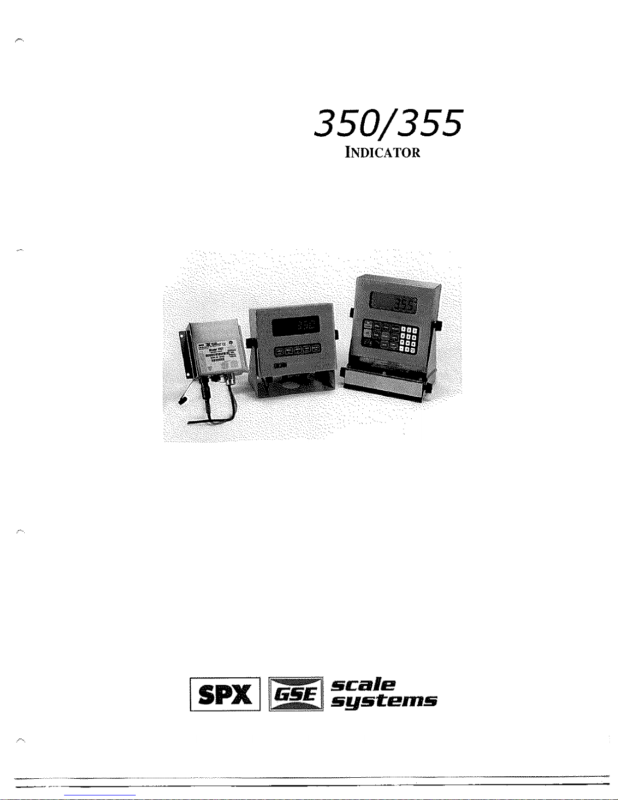
GSE
Model
IS
I
N
TRI
N
SIC
A
LLY
S
A
F
E
Technical
Reference
Manual
Version
1.0
Page 2

,
--
Model
IS
Technical Reference
Manual
Version
1.0
Page 3
GSE
Intrinsically
Safe
Technical
Reference
Manual
Copyright
GSE
Scale
Systems.
All
rights
reserved.
Published
by:
GSE
Systems
Nine
Mile
Road
MI
48375
USA
Information
in
this
Operation
Manual
is
subject
to
change
without
notice
due
to
or
enhancement.
The
information
in
this
manual
is
solely
the
property
of GSE.
No
part
of
this
manual
may
be
or
in
any
form
or
by
any
means,
electronic
or
mechanical,
including
photocopying
and
recording
and
sold
for
any
monetary
figure
without
the
express
written
permission
of
GSE.
GSE
GSE
Scale
Systems
42860
Nine
Mile
Road
Novi,
MI
48375
U.S.A.
Phone:
755-7875
www
GSE
Canada,
Inc.
East
Lake
Road
Alberta
Canada
T4B
2B8
948-992
I
(403)
1449
Page 4
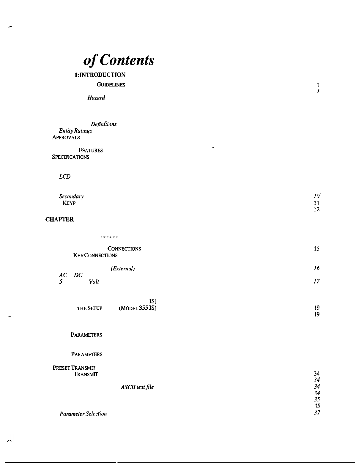
Table
CHAPTER
...................................................................................................................................
1
H
A
ZAR
DO
U
S
A
R
E
A
....................................................................................................................................
Hazard
Grouping
.....................................................................................................................................................
Duration
of
..................................................................................................................................................
2
Temperature
Codes
..................................................................................................................................................
2
Definitions
................................................................................................................................................................
4
Entity
Evaluation
Concept
.......................................................................................................................................
4
Entity
Rating
..........................................................................................................................................
5
...........................................................................................................................................................
5
...................................................................................................................................................................
6
S
TANDAR
D
F
U
NCT
ION
S
.................................................................................................................................................
7
S
T
AN
DARD
...................................................................................................................................................
7
............................................................................................................................................................
7
DISPLAY
........................................................................................................................................................................
8
LED
Display
.............................................................................................................................................................
8
Display
............................................................................................................................................................
9
Annunciators
............................................................................................................................................................
9
350
IS
KEY
PAD
...........................................................................................................................................................
9
Functions
..............................................................................................................................................
355
WEIGH
M
O
D
E
FUNCTIONS
...........................................................................................................................................
2:
INSTALLATION
..................................................................................................................................
13
S
YSTEM
D
I
A
G
R
AM
S
.....................................................................................................................................................
13
O
UTLIN
E
D
RAW
I
N
G
S
.......................................................................................................................................
13
L
O
AD
C
ELL
C
O
N
N
EC
T
I
O
N
S
..........................................................................................................................................
14
C
O
MM
U
N
I
C
A
T
I
O
N
P
O
R
T
.......................................................................................................................
REMOTE
.......................................................................................................................................
15
H
A
ZAR
DO
U
S
A
R
E
A
O
PTI
O
N
S
.......................................................................................................................................
16
Battery
Power
Supply
...........................................................................................................................
Volt
and
8
Excitation
...................................................................................................................................
CHAPTER
3:
CONFIGURATION
..............................................................................................................................
18
to
Power
Supply
(External)
.......................................................................................................................
16
E
NTER
IN
G
THE
SETUP
M
O
D
E
(M
O
DEL
350
............................................................................................................
18
S
E
LECT
IN
G
A
P
ARAM
ETE
R
...........................................................................................................................................
C
H
A
NGIN
G
A
P
A
RAMETE
R
V
ALU
E
...............................................................................................................................
21
Selection
Parameters
.............................................................................................................................................
21
K
E
Y
-
I
N
..................................................................................................................................................
21
S
AVI
N
G
P
A
R
AMETE
R
S
.................................................................................................................................................
22
F
A
CTOR
Y DE
F
A
U
L
T
.....................................................................................................................................................
24
L
IST
O
F
..................................................................................................................................................
25
E
NTE
R
IN
G
M
O
D
E
............................................................................................................
Parameter
Map
Details
..........................................................................................................................................
27
Elements
of
a
Custom
Transmit
.............................................................................................................................
Writing
a
custom
transmit
..............................................................................................................
Entering
ASCII
Text
...............................................................................................................................................
Entering
ASCII
Control
Codes
...............................................................................................................................
SELECTIONS
..................................................................................................................................
32
CUSTOM
..................................................................................................................................................... 34
Accessing
Setup
and
Clearing
Existing
Custom
Transmit
.....................................................................................
Numbers
................................................................................................................................
I
Page 5
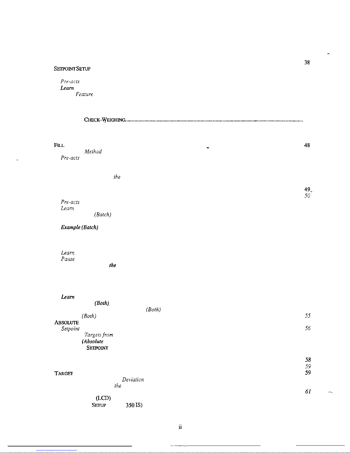
Exiting
Setup
Mode
and
Saving Changes
..............................................................................................................
38
PARTS
COUNTING
........................................................................................................................................................
..........................................................................................................................................................
40
Activation Methods (General)
................................................................................................................................
40
(General)
.................................................................................................................................................
41
Feature
(General)
........................................................................................................................................
41
Pause Fearure
{General)
.......................................................................................................................................
41
Changing
Targets
from the
Weigh
Mode (General)
..............................................................................................
42
Bargraph
(General)
...............................................................................................................................................
43
P
E
RCENT
AGE
46
Setpoint
Activation {Percentage
Check
-
Weighing)
................................................................................................
46
Changing
Targets
from
the
Weigh
Mode
(Percentage
Check- Weighing)
..............................................................
46
Example
(Percentage Check- Weighing)
................................................................................................................
47
.............................................................................................................................................................................
Activation
(Fill)
.........................................................................................................................................
48
(Fill)
.........................................................................................................................................................
48
Learn
Feature
(Fill)
...............................................................................................................................................
49
Pause
Feature
(Fill)
...............................................................................................................................................
49
Changing Targets
from
Weigh
Mode
(Fill)
......................................................................................................
49
Example
(Fill)
........................................................................................................................................................
49
B
A
TC
H
Activation Method (Batch)
.....................................................................................................................................
(Batch)
.....................................................................................................................................................
50
Feature
(Batch)
...........................................................................................................................................
50
Pause
Feature
...........................................................................................................................................
50
.....................................................................................................................................................
51
D
IS
C
H
ARGE
.................................................................................................................................................................
51
Activation
Method
(Discharge)
..............................................................................................................................
52
Pre-acts
(Discharge)
..............................................................................................................................................
52
Feature
(Discharge)
....................................................................................................................................
52
Feature (Discharge)
....................................................................................................................................
53
Example
(Discharge)
.............................................................................................................................................
53
B
O
T
H
...........................................................................................................................................................................
53
Activation
Method
(Both)
.......................................................................................................................................
54
Pre-acts (Both)
.......................................................................................................................................................
54
Change
Target
Weight
Example
(General)
............................................................................................................
43
.........................................................................................................................................................................
Changing
Targets
from the
Weigh
Mode
(Batch)
..................................................................................................
50
...
Target Changesfrom
Weigh
Mode
(Discharge)
..............................................................................................
53
Feature
(Both)
.............................................................................................................................................
54
Pause
Feature
.............................................................................................................................................
55
Target
Changesfrom
the
Weigh Mode
.......................................................................................................
55
Activation
(Absolute
Check
-
Weighing)
....................................................................................................
Changing
the
Weigh
Mode
(Absolute
Check
-
Weighing)
.................................................................. 56
Setpoint Activation {Independent)
..........................................................................................................................
58
Changing Targets
from
the
Weigh
Mode
(Independent)
........................................................................................
Example
(Independent)
..........................................................................................................................................
DEVIATION
CHECK-WEIGHING
......................................................................................................................
Setpoint
Activation
(Target Deviaiion
Check
-
Weighing}
.......................................................................................
60
Changing
Targets
from
Weigh
Mode
(Target Deviation Check- Weighing)
.....................................................
60
Example
(Target Deviation
Check
-
Weighing)
.......................................................................................................
BARGRAPH
SETUP
............................................................................................................................................
61
T
IM
E
AND
D
A
TE
(MODEL
.....................................................................................................................
63
Example
......................................................................................................................................................
C
HECK
-
W
E
IGH
IN
G
.....................................................................................................................................
55
Example
Check-Weighing)
.....................................................................................................................
57
I
NDEPENDENT
O
P
E
RAT
I
O
N
..........................................................................................................................
57
.....
..
Page 6

AND
D
A
T
E
.....................................................................................................................
66
R
E
M
O
TE
O
PERAT
I
O
N
R
E
MOT
E
S
E
RIAL OPER
A
TION
.......................................................................................................................................
66
Display
Capture
..........................................................................................................................................
67
U
P
G
RAD
E
I
N
D
I
C
A
TOR
F
IR
M
W
A
R
E
................................................................................................................................
67
Prepare
for
upgrade
...............................................................................................................................................
68
Load
Flash
File
......................................................................................................................................................
68
...........................................................................................................................................
CHAPTER
4:
CALIBRATION.
...................................................................................................................................
69
M
O
D
E
........................................................................................................................................
69
F
A
S
T
C
A
LIBRAT
I
O
N
P
E
RFOR
M
IN
G
C
A
LIB
R
A
T
I
O
N
........................................................................................................................................
69
First
Zero
...............................................................................................................................................................
Last
Zero
................................................................................................................................................................
72
...................................................................................................................................................
70
False
Zero
..............................................................................................................................................................
74
Only
Zero
............................................................................................................................................................... 76
E
S
T
A
BLISH
IN
G
A
................................................................................................................................................
79
Reset
Calibration
...................................................................................................................................................
77
E
X
IT
IN
G
C
A
LIBRAT
I
O
N
................................................................................................................................................
80
CHAPTER
5:
LEGAL
FOR
TRADE
.......................................................................................................................... 82
.
R
E
Q
U
IREM
ENT
S
................................................................................................................................................
R
E
Q
U
IR
EM
ENT
S
................................................................................................................................................
82
O
THER
...............................................................................................................................................
83
S
EALIN
G
A
N
D
A
U
D
IT
......................................................................................................................................
83
Physical
Seal
..........................................................................................................................................................
84
Audit
Trails
............................................................................................................................................................
84
CHAPTER
7:
TROUBLESHOOTING
.......................................................................................................................
E
RROR
.......................................................................................................................................................
86
Operation
a
86
Setup
Mode Errors
.................................................................................................................................................
87
Calibration
Errors
.................................................................................................................................................
88
Communication
Errors
..........................................................................................................................................
88
Miscellaneous
Errors
.............................................................................................................................................
88
VIEWING
...........................................................................................................................................................
89
M
O
D
E
.............................................................................................................................
89
C
A
LIBRAT
I
O
N
P
ROCE
DUR
E
..................................................................................................................................
91
Hardware
Errors
................................................................................................................................................... 87
Page 7

Page 8
CHAPTER
4
Thank
you
for
selecting
the
GSE
Model
3501355
Intrinsically
Safe
Indicator.
The
Model
350
and
Model
355
continue
the
GSE
tradition
of
Excellence
in
Weighing. A properly
installed
and
maintained
Model
350
or
Model
355
IS
will
provide
many
years
of
reliable, accurate
performance.
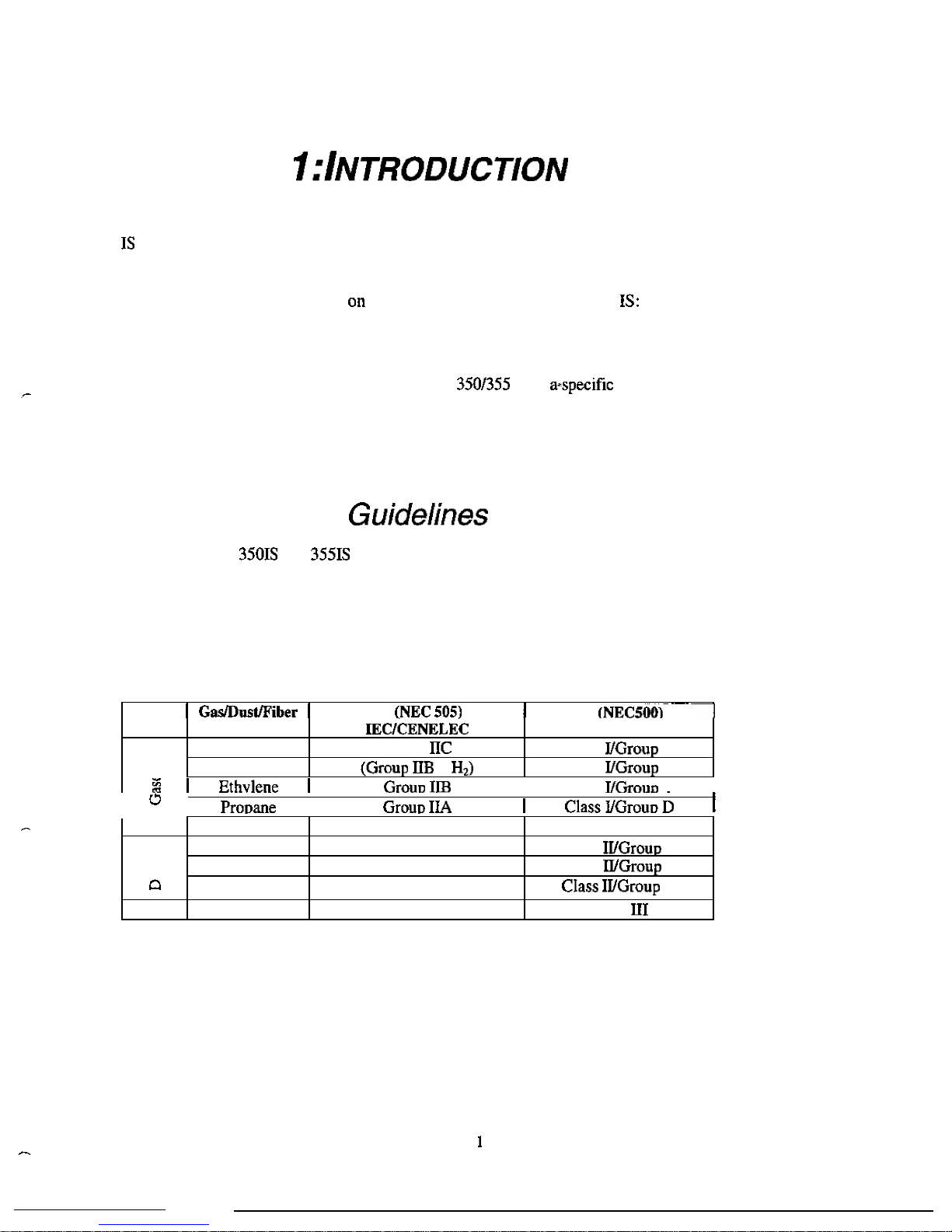
Acetylene Group
Class
A
Hydrogen
+
Class
B
The
chapters
of
this
manual
focus
various
aspects
of
the
Model
3501355
Methane
Metal
Dust
Coal Dust
Grain
Dust
Fibers
4
Chapter
1:
Introduction
Chapter
2:
Installation
Chapter
3:
Configuration
Chapter
4:
Operation
Chapter
5:
Calibration
Chapter
6:
Troubleshooting
Group
I
*
Mining
*
None
Class
E
None
Class
F
None
G
None
Class
Hazardous
Area
Hazardous
Area
Guidelines,
Features
and
Specifications.
Installation
of
Indicator
and
Options.
Setup the
IS
to
application.
Using
the
Model
3501355
IS.
Calibrate
the
indicator
to
a
scale.
Troubleshooting
help
and
error
messages.
The
GSE
Models
and
instruments
are
approved
by
FM
Approvals
as
intrinsically
safe
for
use
in
hazardous
areas.
An intrinsically
safe
device
has
been
proven
through
calculation
and
testing that
it
cannot
produce
enough electric
or
thermal
energy
under
normal
or
fault
conditions
to
cause ignition
of
flammable
material
present
in
the
atmosphere.
The
hazardous
area
is
defined
in
terms
of
how
long
the
hazard
is
present,
how
easily
it
is
ignited,
and
what
maximum temperature
can
be
present.
H
AZAR
D
G
R
O
U
PIN
G
I I
US
US
t
Class
c
I
I
I
I
I
I
Page 9
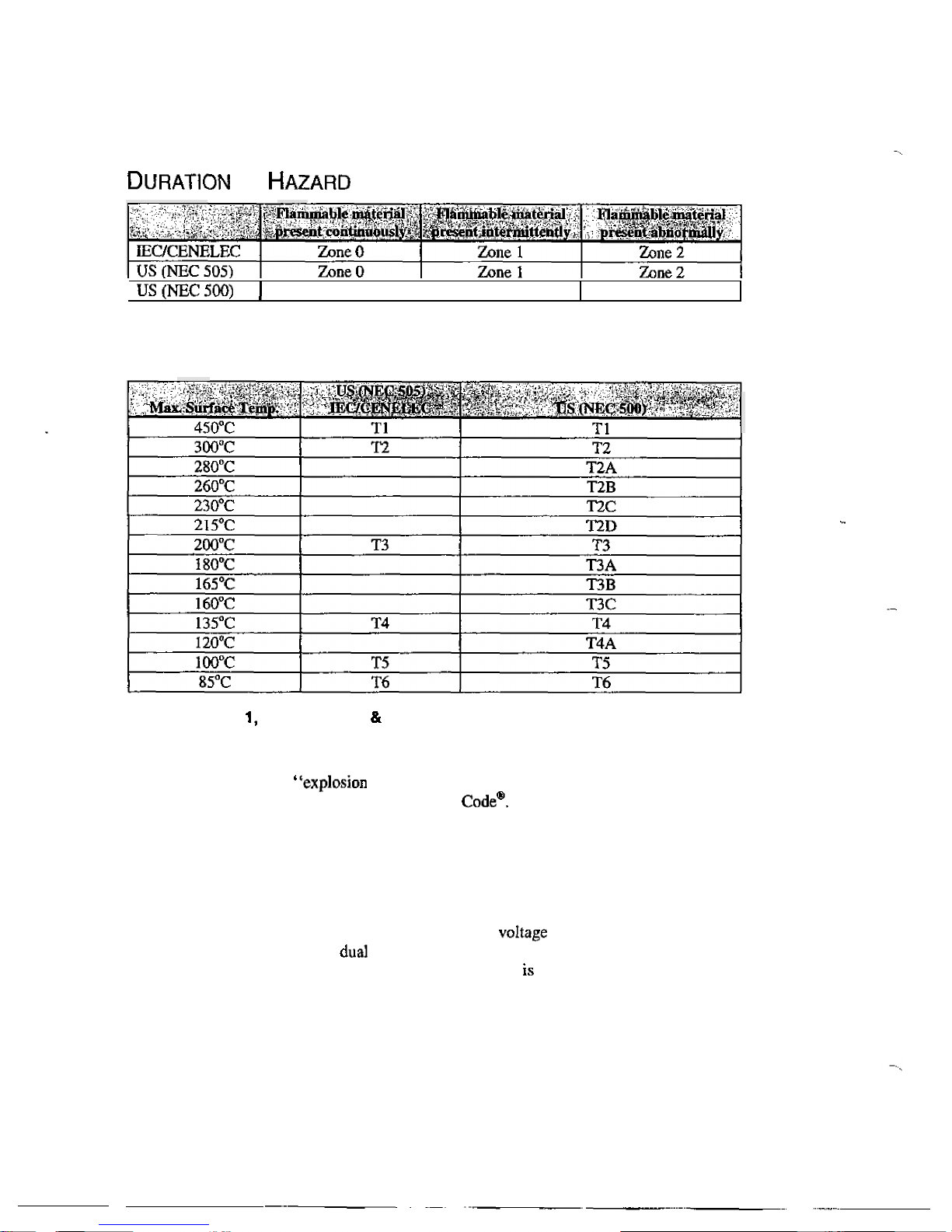
OF
Division
1
Division
2
T
EMP
ERA
T
U
R
E
C
O
D
E
S
Class
I,
Division
Groups
A,
B, C D
Class
I,
Division
1
locations
are
those
in
which
hazardous
concentrations
of
flammable
gases
or
vapors
exist
continuously, intermittently
or
periodically
under
normal
operating
conditions.
Electrical equipment
for
use
in
such
locations
may
be
proof,”
“intrinsically
safe,”
“purged”
or
otherwise
protected
to
meet
the intent
of
Articles
500
of
the
National
Electrical
Explosion
proof
protection consists
of
equipment
designed
to
be
capable
of
containing
an
internal
explosion
of
a
specified
flammable
vapor-air
mixture.
In
addition,
the
equipment must operate at
a
safe
temperature
with
respect
to
the
surrounding
atmosphere.
Intrinsically
safe
electrical
equipment
and
associated
wiring
are
incapable
of
releasing sufficient
electrical
or
thermal
energy
to
cause
ignition
of
a
specific
hazardous
material
under
“normal”
or
“fault”
operating
conditions.
Normal
operation
assumes
maximum
supply
and
rated
environmental
extremes;
fault
conditions
assume
any
single
or
independent
electrical
faults
plus
field
wiring
open,
shorts
or
connections
to
ground. Equipment
rated
as
intrinsically
safe
recognized
by
Article
500
as
safe
for
use
in
hazardous
locations
without
special
enclosures
or
physical
protection that
would
otherwise
be
required.
Purged
systems
have
fresh
air
or
an
inert
gas
under positive
pressure
to
exclude
ignitable
quantities
of
flammables
from
the
electrical
equipment
enclosure.
Equipment
Approved
for
Division
1
locations
shall
be
permitted
in Division
2
locations
of
the
same
class,
group
and
temperature
class.
2
Page 10

Class
I,
Division
2,
Groups
A,
8,
C
&
D
Class
I,
Division
2
locations
are
those in which hazardous concentrations
of
flammables exist only
under
unlikely
conditions
of operation.
As
such,
equipment
and
associated
wiring
which
are
incapable
of
sufficient electrical
and
thermal
energy
to
ignite
flammable
gases
or
vapors
under
“normal”
operation
and
environmental conditions
are
safe
to
use
in
Class
Division
2
locations.
Class
I,
Zone
0,
Groups
A
Class
I,
Zone
0
location
is
a
location
in which ignitible concentrations
of
flammable
gases
or
vapors
are
present continuously;
or
(2)
in which ignitible concentrations
of
flammable gases
or
vapors
are
present
for
long
periods
of
time. Electrical apparatus for
use
in
such
locations
may
be
type
of
protection “ia”
Intrinsic Safety.
Class
I,
Zone
1,
Groups IIC,
A
Class
I,
Zone
1
location is a location
(I)
in
which
ignitible concentrations
of
flammable
gases
or
vapors
are
likely
to
exist
under
normal
operating conditions;
or
in
which
ignitible concentrations
of
flammable
gases
or
vapors
may
exist
frequently
because
of
repair
or maintenance operations
or
because
of
leakage;
or
(3)
in
which
equipment
is
operated
or
processes
are
carried
on,
of
such
a
nature
that
equipment
breakdown
or
faulty operations could
result
in
the
release
of
ignitible concentrations of flammable
gases
or
vapors
and
also
cause
simultaneous
failure
of
electrical
equipment
in
a
mode
to
cause
the electrical equipment
to
become a source
of
ignition;
or
(4)
that
is
adjacent to
a
Class
I,
Zone
0
location
from
which
ignitible
concentrations
of
vapors
could
be
communicated, unless communication
is
prevented
by
adequate
positive
-
pressure
ventilation
from a source
of
clean air
and
effective
safeguards
against ventilation failure
are
provided. Electrical apparatus
for
use
in
such
locations
may
be
type
of
protection
“d”
Flameproof,
“e”
Safety,
Safety,
Encapsulation,
Oil Immersion,
Pressurized
or
Pow
led.
Note:
Electrical
apparatus
Approved
for
use
in
Class
I,
Zone
locutions
shall
be
permitted
in
Class
I,
Zone
locations
of
the
group
and
temperature
class.
Class
I,
Zone
2,
Groups
&
A
Class
I,
Zone
2
location
is
a
in
which
ignitible concentrations
of
flammable
gases
or
vapors
are
not
likely
to
occur
in
normal
operation
and
if
they
do
occur
will
exist
only
for
a
short
period;
or
(2)
in
which volatile
flammable
liquids, flammable
gases
or flammable
vapors
are
handled,
processed
or
used,
but
in which
the
liquids,
gases
or
vapors
normally
are
confined within
closed
containers
or
closed
systems
from
which
they
can
escape
only
as
a
result
of
accidental
rupture
or
breakdown
of
the
containers
or
system
or
as
the
result
of
the
abnormal
operation
of
the
equipment
with
which
the liquids
or
gases
are
handled,
processed
or
used;
or
(3)
in
which
ignitible concentrations
of
flammable
gases
or
vapors normally
are
prevented
by
positive
mechanical
ventilation,
but
which
may
become
hazardous
as
the
result
of
failure
or
abnormal
operation
of
the ventilation equipment;
or
(4)
that is adjacent
to
a
Class
I,
Zone
location,
from
which
ignitible
concentrations
of
flammable
gases
or
vapors
could
be
communicated. unless
such
communication
is prevented
by
adequate positive-pressure ventilation
from
a
source
of
clean
air
and
effective
safeguards
against
ventilation
failure
are
provided.
Electrical
apparatus
for
use
in such locations
may
be
type
of
protection
Restricted Breathing
or
Pressurized.
Note:
Electrical
apparatus
Approved
for
use
in
Class
I,
Zone
or
Zone
I
locations
shall
be
permitted
in
Class
I,
Zone
2
locations
of
gas
and
temperature
class.
Class
Divisions
1 & 2,
Groups
E,
F
G
Electrical equipment suitable
for
use
in
Class
11
locations,
as
defined
by
the
National
Electrical
is
constructed to
exclude
ignitable
amounts
of
dust
from
the equipment enclosure.
Approved
equipment
of
this
type
has
also
been
evaluated
to
assure
that
hazardous
temperatures
do
not
exist.
Equipment
listed
as
3
Page 11
suitable
for
Class
locations
is
“dust-ignitionproof”
or
otherwise designed
to
meet
the
intent
of
Articles
500
and
502
of
the National
Electrical
Class
111,
Divisions
1
2
are
those
which
are
hazardous
because
of
the
presence
of
ignitable
fibers
or
flyings.
Equipment listed for installation in
Class
locations is
designed
to
exclude
the
fibers
and
flyings
from
the
equipment enclosure
and
to
function without developing excessive
surface
temperatures.
D
EFINITION
S
Apparatus - Apparatus, including
Category
ia
and
ib apparatus,
in
which
the
circuits
are
not
necessarily
intrinsically
safe
themselves, but
which
affect
the
energy
in the intrinsically
safe
circuits
and
are
relied
upon
to maintain intrinsic
safety.
Associated
electrical
apparatus
may
be
either:
a)
Electrical
apparatus
has
an
of
protection
for
use
in
the appropriate potentialiy
flammable
atmosphere.;
or
b) Electrical
apparatus
not
so
protected
and thus not suitable
for
use
in
a
potentially flammable
atmosphere.
Drawing
A
drawing
or
other
document
provided
by
the
manufacturer
of
the
intrinsically
safe
or
associated
apparatus
that details
the
allowed
interconnections
to
other
circuits
or
apparatus.
If
the
intrinsi
-
cally
safe
ox
associated apparatus
is
investigated
under
the
entity
concept.
the
control
drawing
will
the applicable electrical
parameters
to
selection
of
apparatus
for
interconnection.
Concept
-
A
method used
to
determine acceptable combinations
of
intrinsically
safe
apparatus
and
connected
associated
apparatus
that
have
not
been
investigated
in
such
combination.
A
location
in
which
fire
or
explosion
hazards
may
exist
due
to
an
explosive atmosphere
of
flammable
gases
or
vapors,
flammable
liquids. combustible
dust.
or
easily
ignitable
fibers
or
flyings.
Intrinsically
Safe
Circuit
-
A
circuit in
which
any
spark
or
thermal
effect,
produced
either normally
or
in
specified fault conditions,
is
incapable,
under
the
test conditions
prescribed
in
this
standard,
of
causing
ignition
of
a
mixture
of
flammable
or
combustible
material
in
air
in
the
mixture’s
most
easily
ignited
concentration.
Nonincendive
Circuit
-
A
circuit,
other
than
field
wiring,
in which
any
arc
or
thermal
effect
produced
under
intended operating conditions
of
the
equipment
is
not
capable, under specified test conditions,
of
igniting
the
flammable
gas-air,
vapor-air,
or
dust-air mixture.
E
NTITY
E
VALUATION
C
ONCEPT
The
Model
35015
and
indicators
have
been
approved
under
the
entity
evaluation
concept,
which
allows
the
interconnection
of
intrinsically
safe
devices
in
hazardous
areas
even though these devices
were
not specifically
approved
in
this combination. This
means
that not only
can
the instrument
be
used with
GSE
FM
Approved Ioadcells
and
peripherals, but
they
can
also
be used with
any
manufacturer’s
FM
Approved
loadcells and
peripherals
provided
that they
have
matching
entity ratings
and
are
approved
for
the
appropriate
hazardous
area.
The
criteria
for
interconnection
is
that
the maximum input
voltage
and
current, which intrinsically
safe
apparatus
can
receive
and
remain intrinsically
safe,
considering faults, must
be
equal
to
or
greater than the
maximum
output
voltage
and
current
levels
which
can
be
apparatus,
considering
faults
and
applicable factors.
In
addition,
the
maximum
internal
capacitance
and
inductance
of
the
intrinsically
safe
apparatus, including ihterconnecting wiring,
must
be
less
than
or
to
the
maximum
allowed capacitance
and
inductance which
can
be
safely
connected
to
the
associated
apparatus.
If
these
4
Page 12
criteria
are
met,
then
the
combination
may
be
connected
and
remain intrinsically
safe.
If
the
specific
capacitance
and
inductance
ratings
of
the
wiring
are
unknown,
use
a
capacitance
of
and
an
inductance
of
When
connecting
a
Model
or
to
another
intrinsically
safe
device,
the
entity
ratings
must
be
compared
and satisfy
the
conditions
shown
in
the
following
table.
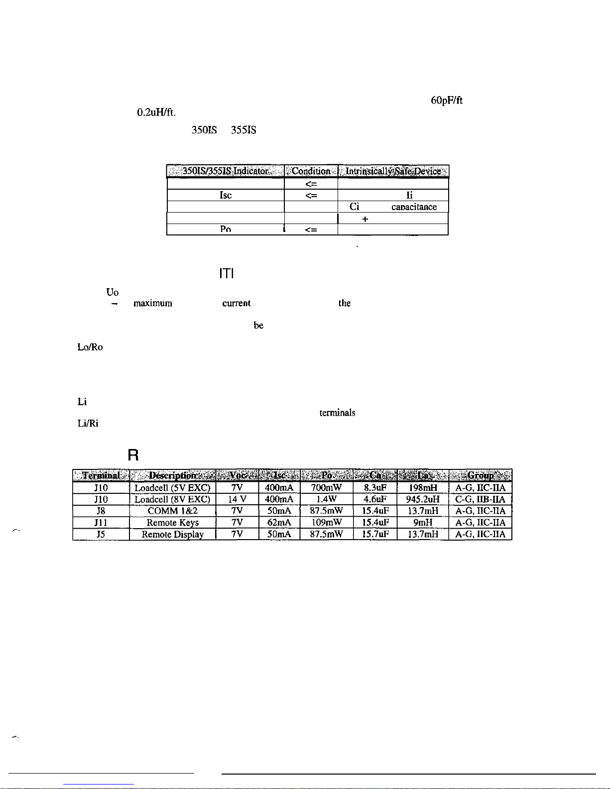
voc
Ca
Vmax
or
Ui
Imax
or
>=
+
cable
La
>=
Li
cable
inductance
E
NTITY
R
A
T
I
N
G
D
E
FI N
O
N
s
Voc
or
-
the
maximum
open
circuit
voltage
that
may
be
present
at
the
specified terminals
Isc
or
Io
the mimum
short
circuit
that
may
be
present
at
specified
terminals
Ca
or
Co
-
the
maximum
capacitance
that
may
be
connected
to
the
specified
terminals
La
or
Lo
-
the
maximum
inductance
that
may
connected
to
the
specified
terminals
Po
-
the
maximum output
power
from
the
specified
terminals
-
inductance to resistance
ratio
that
indicates the maximum
inductance
per
ohm
of
resistance
that
can be
connected
to
the
specified
terminals
Vmax
or
Ui
-
the
maximum
voltage
that
may
be
connected
to
the
specified
terminals
Imax
or
Ii
-
the
maximum
current
that
may
be
connected
to
the
specified
terminals
Ci
-
the
capacitance
present
at
the
specified
terminals
-
the
inductance
present
at
the
specified
terminals
Pi
-
the
maximum
power
that
may
be
supplied
to
the
specified terminals
-
the
maximum
internal
inductance
to
resistance
ratio
at
the
specified
terminals
Pi
E
NTITY
A
T
I
N
G
s
5
Page 13
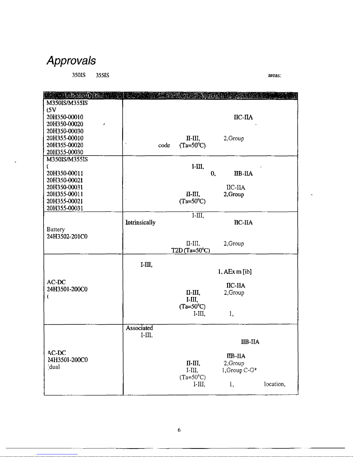
The
Model
and
indicators
and
options
have
been
approved
for
the
following
hazardous
Excitation)
8V
Excitation)
Power
Supply
Option
Power
Supply
Option
:single output
used)
Power
Supply
Option
outputs
used)
Intrinsically
Safe
for Class
I-BI,
Division
1 , Group
A-G
Intrinsically
Safe
for
Class
I,
Zone
0,
Group
Nonincendive
for
Class
I,
Division
2,
Group
A-D
Nonincendive
for
Class
I,
Zone
2,
Group
IIC-IIA
Suitable
for
use
in
Class
Division
F-G
Temperature
T4
Intrinsically
Safe
for
Class
Division
1,
Group
C-G
Intrinsically
Safe
for
Class
I,
Zone
Group
Nonincendive
for
Class
I,
Division
2,
Group
A-D
Nonincendive
for
Class
I,
Zone
2,
Group
Suitable
for
use
in
Class
Division
F-G
Temperature
code
T4
Intrinsically
Safe
for
Class
Division
1,
Group
A-G
Safe
for
Class
I,
Zone
0,
Group
Nonincendive
for
Class
I,
Division
2,
Group
A-D
Nonincendive
for
Class
I,
Zone
2,
Group
IIC-IIA
Suitable
for
use
in
Class
Division
F-G
Temperature
code
Associated
Apparatus
with
Intrinsically
Safe
Connections
for
Class
Division
1,
Group A-
G
Encapsulated
for
use
in
Class
I,
Zone
Group
IIC-IIA
Nonincendive
for
Class
I,
Division
2,
Group A-
D
Nonincendive
for
Class
I,
Zone
2,
Group
Suitable
for
use
in
Class
Division
F-G
Suitable
for
use
in
Class
Division
I
,Group
A-G*
Temperature
code
T4
*
When
installed
in
a
Class
Division
Group
A-G
location,
conduit must
be
used
on
the
AC
supply cable.
Apparatus
with
Intrinsically
Safe
Connections
for
Class
Division 1,
Group
C-G
*
Encapsulated
for
use
in
Class
I.
Zone
0,
Group
*
Nonincendive
for
Class
I,
Division
2,
Group
C-D
Nonincendive
for
Class
I,
Zone
2,
Group
Suitable
for
use
in
Class
Division
F-G
Suitable
for
use
in
Class
Division
Temperature
code
T4
*
When
installed
in
a
Class
Division
Group
C-G
conduit must
be
used
on
the
AC
supply
cable.
Page 14
r
-
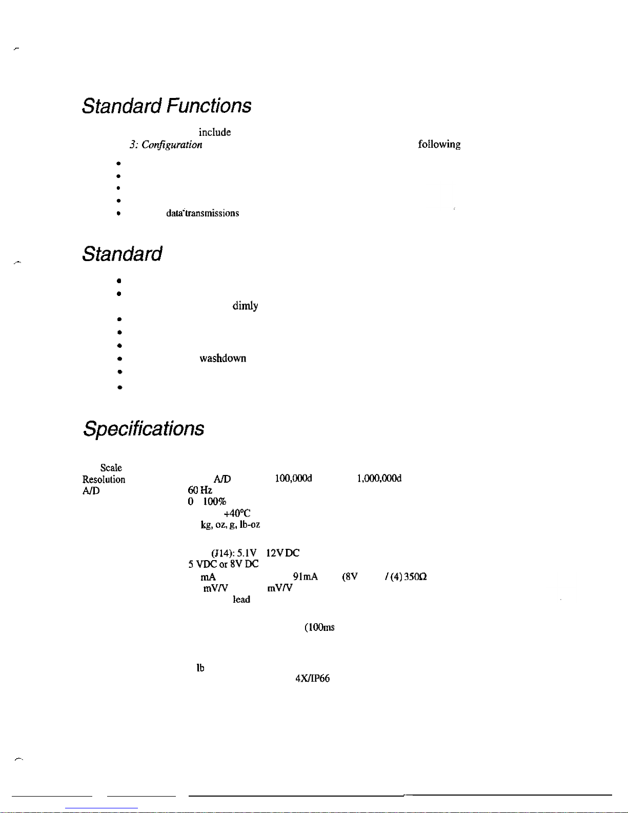
The
Model
350
and
355
IS
built-in
functions
that
you
can
enable
through
the
Indicator
Setup.
Refer
to
Chapter
for
information
on
the
setup
and
operation
of
the
standard
functions:
Check-weighing
Parts
counting
Remote
key
operation
Custom
Selectable,
built-in
data
transmission
formats
Features
Three
display
choices
(LCD,
LCD
backlit
and
LED).
LED
model
uses
low
current
high
efficiency
display
digits
and
annunciators
to
save
battery
life
and
adds
brightness
to
lit
areas.
Real
time clock
with
battery
backed
time
and
date.
Two
RS-232
communication
ports.
Model
355
has
a
numeric
keypad
Stainless
Steel
enclosure
Up
to
(4)
350
ohm
loadcells
Easily
update
firmware
via
the
RS-232
port
PERFORMANCE
Full
(F.S.)
Conversion
Zero
Track
Operating
Temperature
Units
of
Measure
ELECTRICAL
Power
Requirement
Excitation
Voltage
Excitation
Current
F.S.
Signal
Input
Signal
Connection
Selectable
0
to
999,999
20-bit
converter,
displayed,
internal
-
of
Full
Scale
-
10°C
to
Ib,
Input
-
57
max.
(5V
EXC)
or
max.
EXC)
bridge
0.1
min
-
10
4
lead
or
6
with
sense
PROCESS
CONTROL
Remote
Input
EN
CLOSURE
Shipping
Weight
Material
Mounting
2
momentary
contact
closure
minimum)
TARE,
PRINT,
ZERO
7
(3
kg)
304
Stainles
Steel,
NEMA
Design
2
swivel
brackets
are
available
for
battery
or
AC
operation
7
Page 15
DISPLAY
LED
LCD
COMMUNICATION
KEYPAD
350
355
IS
RS-232
6-digit
weight
display,
0.8'
12
LED
annunciators
for
operational
status
weight
display,
1.0'
height
12
LCD
operational
status.
Built
in
LCD
status
bargraph.
Also
available
with
backlight
(2)
communication
ports,
1
with
hardware
handshaking
key,
durable
elastomeric
(rubber)
22
full
numeric,
durable elastomeric
(rubber)
SAFE
AREA
OPTIONS
Battery
Charger
HAZARDOUS
AREA
OPTIONS
Battery
Charges
completely discharged
battery
option
in
3.5
hours
Universal
AC
input
Stainless
steel
enclosure,
mounts
to
indicator
swivel
bracket.
200
hours
continuous
use
with
display
1
loadcell,
and
hours
continuous
use
with
LED
display + 1
loadcell.
Charge
time
3.5
hours
with
battery
charger
option.
AC
to
Power
Supply
Stainless
steel
enclosure.
Powers
up
to
2
indicators
(2
indicators
can
only
be
powered
in
Groups C-
G
hazardous
area).
Wall
mount.
AC
input
Power
Extension
Cable
Allows
the
AC-DC
power
supply
to
be
mounted
away
the
indicator.
25
and
50
feet
lengths
available.
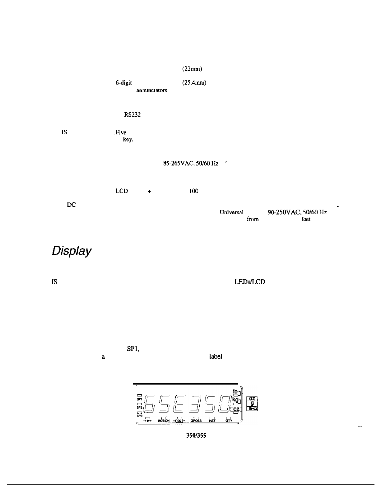
The
Model
350
and
355
intrinsically
safe
indicators
are
available
with
a
six
digit,
7-segment
red
LED
display,
six
digit,
7-segment
black
LCD
display
or
7-segment
backlit
LCD
display.
The
Model
350
and
355
will
display
alphanumeric
data,
but
due
to
the
nature
of
7-segment
and
the
limitation
of
six
digits,
some
information
is
abbreviated.
All
segments
and
annunciators
are
illuminated
for
a
brief
display
test
upon
power
up.
The
current
gross
weight
is
then
displayed
in
default
units.
LED
D
ISPLA
Y
The
LED
display
is
a
six
digit, 7-
segment
bright
red
LED
screen
with
12
annunciators
to
show
weight
and
status
information.
The
SP2,
and
SP3
annunciators
are
red,
green,
and
yellow.
Also
there
is
an
annunciator
for
third unit under
kg.
Place
the
third
unit
the
third annunciator
(the
third
unit
is
available
on
both
the
LED
and
LCD
displays).
See
page
28
for
third
unit
setup.
Figure
1:
Model
IS
LED
Display
a
Page 16
LCD
D
ISPLA
Y
The
LCD
display
is
a
six digit,7-segment
black
LCD
screen
with
12
annunciators
and
a
bargraph
to
show
the
operational
status.
Figure
2:
Model
IS
LCD
Display
A
N
NUNCI
A
T
ORS
Annunciators
provide
mode
and
status
information. When ilIuminated,
they
indicate
the
conditions:
MOTION
LO
GROSS
NET
lb
g
350
IS
KEYPAD
Setpoint
activated
(relay
1
closed).
Setpoint
activated (relay 2 closed).
Setpoint
activated (relay 3 closed).
Displayed
weight
is
at
display
graduation).
Scale
is
in
motion. Motion inhibited
transmits
and motion inhibited setpoint
activation will
be
delayed
until
motion
ceases.
Lights when
the
battery
reaches a low
tolerance.
Displayed
value
represents
the
current
gross
weight.
Displayed value
represents
the
current net weight.
Displayed
value
represents
the
current
piece
quantity (Count).
The
displayed
value
is
represented
in pounds.
The
displayed value
is
represented in
kilograms.
The
displayed
value
is
represented
in
either
ounces,
pound
ounces
or
grams.
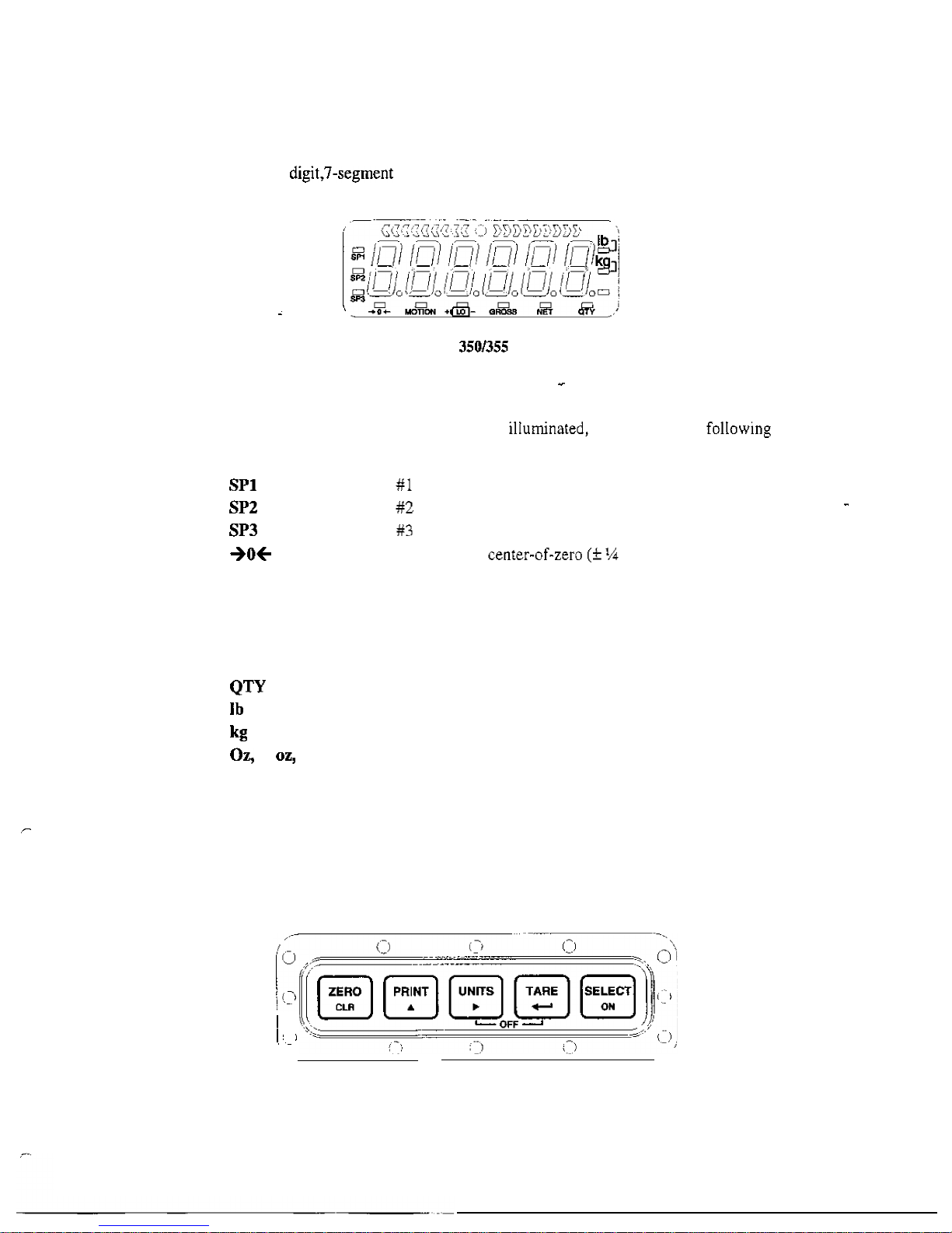
The
Model
350
IS
offers
a
sealed
5-button
elastomer
keypad
is
used
for
operator
input.
Each
key
is
assigned
two distinct functions.
Various
key
combinations
are
also
used.
Each
key
has
secondary functions; allowing
an
operator
to
enter
target
values,
perform
piece
samples,
access
setup
parameters,
etc.
Figure
3:
Model
350
IS
Keypad
9
Page 17
S
E
C
O
NDA
R
Y
F
U
NCT
I
ONS
.
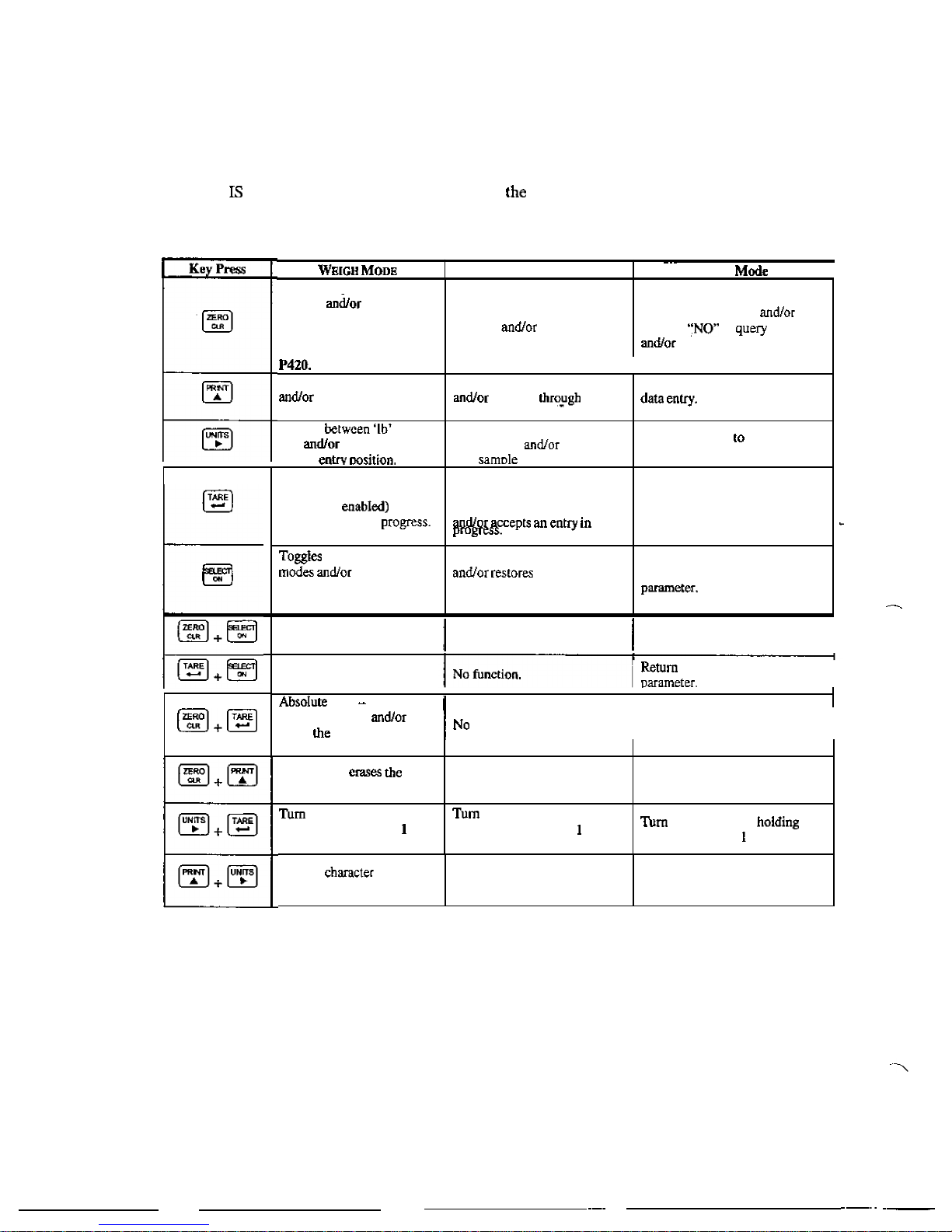
The
Model
350
keypad
performs
different functions
in
Weigh
Mode,
the
Setup
Mode,
and
the
Calibration
Mode.
Secondary
functions
for
each
key
allow
you
to
perform
additional
tasks.
Count
Mode
Setup
function
clears
an
entry
in
progress.
Hold
this
key
on
power-up
to
turn
on
the
display
regardless
of
a
quantity
zero
function
clears
an
entry
in
progress.
Exits
the
Setup
Mode
answers
to
prompts
clears
an
entry in
progress.
Performs
a
print
function
'scrolls'
through
digits
during
setpoint entry.
Toggles
and
'kg'
advances
cursor
to
next
Performs
a
print
function
'scrolls'
digits
during
setpoint
entry.
Toggles
through
standard
sample
sizes
begins
a
new
entrv.
'Scrolls'
through
digits
during
Advances
cursor
next
entry
position
andor
cycles
prompts.
No
function.
Access
Setup
Mode.
Access
Setup
Mode.
I
Perform
an
auto-tare
function
(if
andlor
accepts
an
entry
in
No
function.
Accepts
an
entry
in
progress
andlor
'scrolls'
through
parameter
sub-sct selections
andlor
answers
'YES'
to
query
prompts.
Performs
an
auto-tare
function
and
requests a piece
sample
to
the
previous
setup
I
between display
restores
power
to
the
indicator (if
auto
-
shutoff
enabled).
I
I'
clear
clears
an
Toggles
between
display
modes
power
to
the
enabled).
Advances
to
the
next
setup
indicator
(if
auto-shutoff
function.
entry
in
progress
clears
value
of
a
parameter.
Backspace
-
right
-
most
digit
during
data
entry.
Clears
any
entry
in
progress.
I
Backspace
-
erases
the
right
-
most digit during sample
entry.
Backspace
-
erases
right-most
digit during data entry.
off
indicator
by
holding
key
for
approximately
second.
off
indicator
by
holding
key
for
approximately
second.
off
indicator
by
key
for
approximately
second.
Reverse
scroll
during data
entry.
10
.
Reverse
character
scroll
during
sample
entry.
data
entry.
Reverse
character
scroll
during
Page 18

355
Keypad
The
Model
355
IS
keypad
performs
different
functions
in
Weigh
Mode,
the Setup
Mode,
and
the
Calibration
Mode.
The
number
keys
make
entering
a
tare
value
or
average
piece
weight
easier.
Key
-
-
W
E
IGH
M
O
D
E
Performs
a
gross
zero
function
clears
an
entry
in
progress.
Performs
a
print
function
‘scrolls’
through
digits
during
setpoint entry.
Toggles
between
’Ib’
and
‘kg’
advances
cursor
to
next
entry
position.
Performs
an
auto-tare
function
(if
enabled)
andor
accepts
an
entry
in
progress.
If
the
tare
weight
is
known,
key
in
the
value
and
press
Toggles
between
display
modes
restores
power
to
the
indicator
(if
auto-shutoff
enabled).
Performs
a
sample.
If
a
number
is
keyed
in
hand,
it
will
be
used
as
the
sample
size.
Accepts
an
entry.
Clears
an
entry in
progress.
this
key
on
power-up
to
turn
on
the
display
of
setpoints
are
enabled, causes
a
process
to
start
or
resume.
See
parameter
5003
on
page
3
for
details
on
enabling
the
function.
Count
Mode
Performs
a
quantity
function
andlor
clears
an
entry in
progress.
a
print function
andlor
‘scrolls’
through
digits
during
setpoint entry.
Toggles
through
standard
sample
sizes
and/or
begins
a
new
sample
entry.
Performs
an
auto-tare
function
andlor
accepts
an
entry
in
progress.
Toggles
between
display
modes
andor
restores
power
to
the
indicator (if
auto-shutoff
enabled).
Performs
a sample.
IC
a
number
is
in
before
hand,
it
will
be
used
as
the
sample
size.
Performs
a
quantity
zero
function
andlor
clears
an
entry
in
progress.
If
setpoints
are
causes
process
to
start or
resume.
See
parameter
5003
on
page 31
for
details
on
enabling
the
function.
Setup
Mode
Exits
the
Setup
Mode
to
query
prompts
clears
an
entry
in
progress.
‘Scrolls’ through
digits
during
data entry.
Advances
cursor
to
next
entry
position
cycles
prompts.
Accepts
an
entry
in
progress andlor
through
parameter
selections
answers
‘YES’
to
query
prompts.
Advances
to
the
next
setup
parameter.
Accepts
entry.
Exits
the
Setup
Mode
answers
“NO
to
query
prompts
andlor
clears
an
entry
in
progress.
No
function
Page 19
Key
Press
W
E
I
G
H
Count
Setup
Mode
If
setpoints
are
enabled,
causes
a
pause.
Press
again
to
abort
the
parameter
on
page
3
1
for
details
on
enabling
the
stop
function.
Wake
up
the
indicator
if
in
mode.
Turn
on
the
indicator
if
power
is
Access
the
target
entry
mode.
See
parameter,
on
page
3
I
for
details
on
enabling
target
function.
If
setpoints
are
causes
a
pause.
Press
again
to
abort
the
process.
parameter
5002
on
page
31
for
details
on
enabling
the
stop
function.
Wake
up
the
indicator
if
in
sleep
mode.
on
the
indicator
if
power
is
off.
Access
target
entry
mode.
See
parameter
on
page
3
1
for
details
on
enabling
the
target
function.
No
function
down
the
key
while
power
is
applied.
If
the
keypad
was
enabled,
the
display
will
show
To
reestablish
the
keypad
as
a
350
IS,
hold
down
the
key
of
the
350
IS
keypad
while
is
applied
by
pressing
the
key.
urn
for
second.
ott
no
for
Weigh
Mode
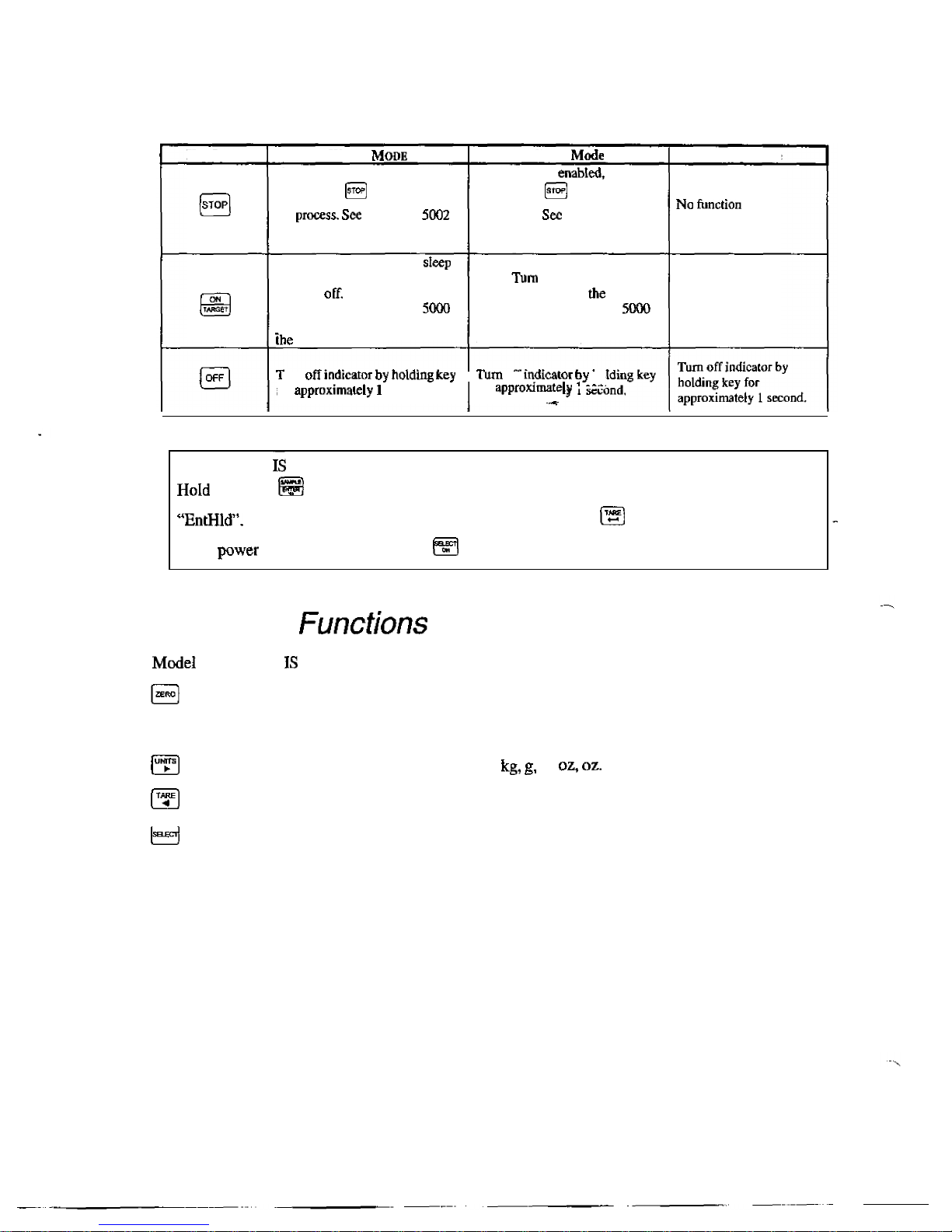
The
350
and
355
keypads
have
five
primary
Weigh
Mode
functions:
Performs
a
gross
zero
and
selects
the
gross
mode.
Initiates
data
transmission
out
the
communication
port.
Toggles
the
units
of
measure
between
lb,
lb
Tares
any
displayed
weight
and
selects
the net
mode.
Toggles
the
display
between
GROSS,
NET,
QUANTITY
and
setpoint
TARGETS
(if
enabled).
12
Page 20
,
-
A
CHAPTER
INSTALLATION
Diagrams
The
control
drawing
details
the allowed
interconnections
between
the
indicators,
their
options,
and
other
possible
devices.
The
drawing
also
shows
the
entity
ratings
of
the
indicators
to
allow
easy
selection
of
other
devices
approved
under
the entity
concept.
See
the
system
diagrams
included
with
the
350
or
355
IS
indicator.
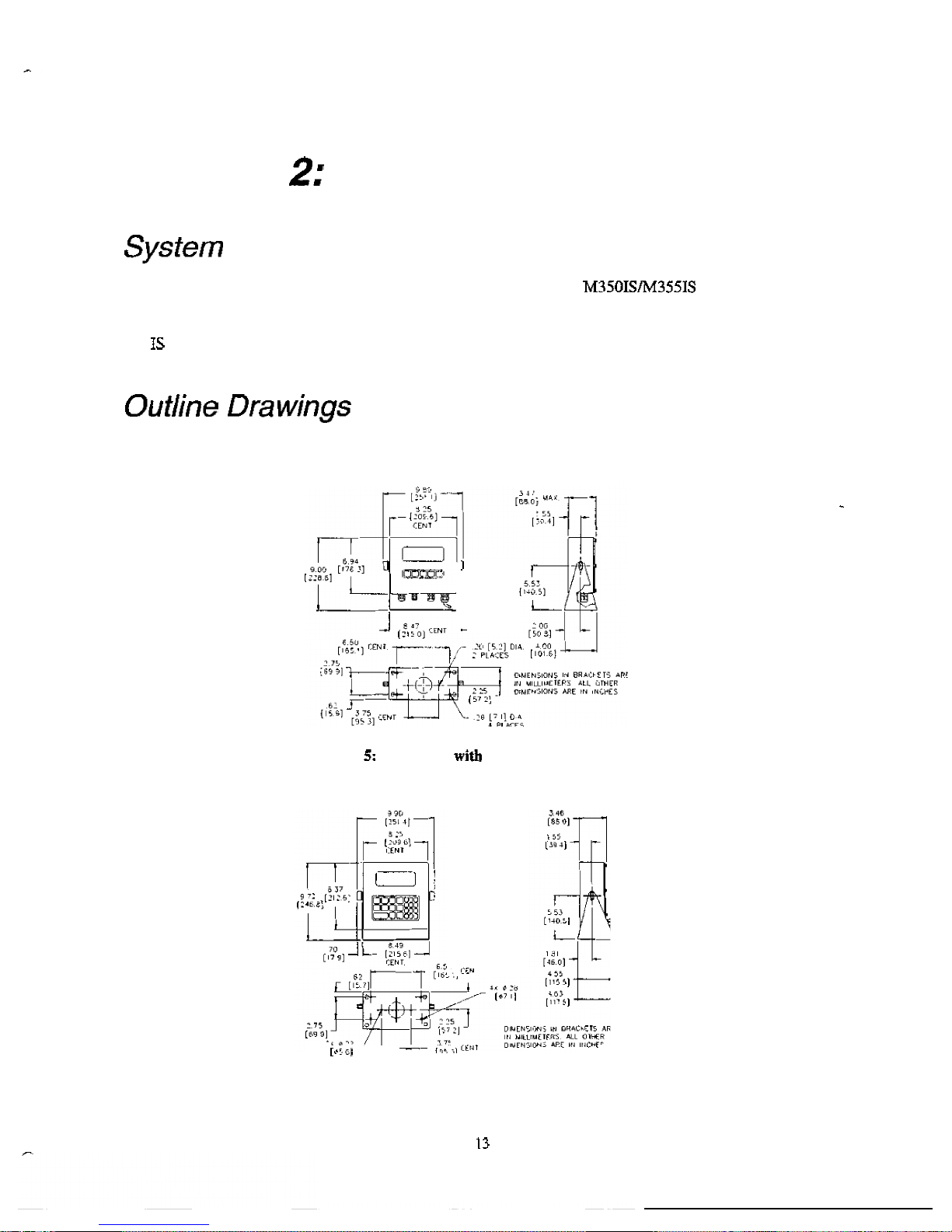
The
outline drawings
provide
measurements
needed for
indicator
installation.
I
Figure
Model
350
Standard
Swivel
Bracket
,
r
,
-
-
Figure
6:
Model
355
IS
with
Standard
Swivel
Bracket
Page 21
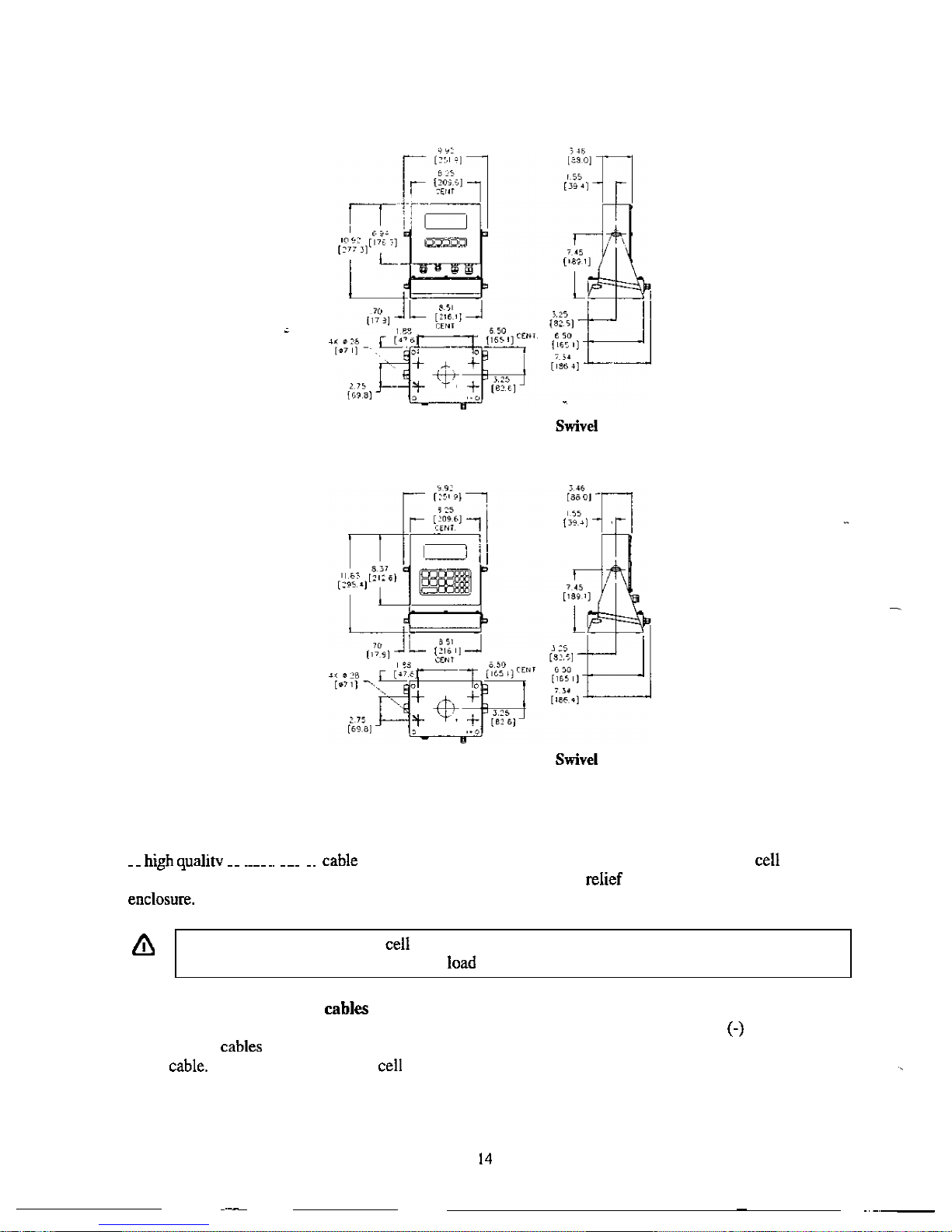
Figure
7:
Model
350
IS
with
Battery
Bracket
Figure
8:
Model
355
IS
with
Battery
Bracket
Load
Cell
Connections
A
braided
shield
with
16
to
24
AWG stranded
wire
is
recommended
for
load
or
.
.
,
. .-
. .
summing
box
connections.
Rout
the
load
cell
cable
through
the
strain
supplied
on
the
bottom
of
the
Either
four
or
six
conductor
cables
can
be
used.
Do
not
tin
the
ends
of
the
load
wire!
A
terminal
connection
free
from
the
effects
of
vibration
and
oxidation
can
be
assured
only
if
the
cell
terminals securely
grip
a
bare,
stranded
wire.
When
using
four
conductor
move
the
sense
jumpers
to
the
internal
position.
When
using
six
conductor
cables
move
the
sense
jumpers
to
the
external
position.
Utilizing
the
(+)
and
Sense
leads
of
six
conductor
provides
compensation
for
variations
in
the
excitation
voltage
due
to
resistance
changes
in
the
See
Figure
9
for
the
load
connector.
.
Page 22
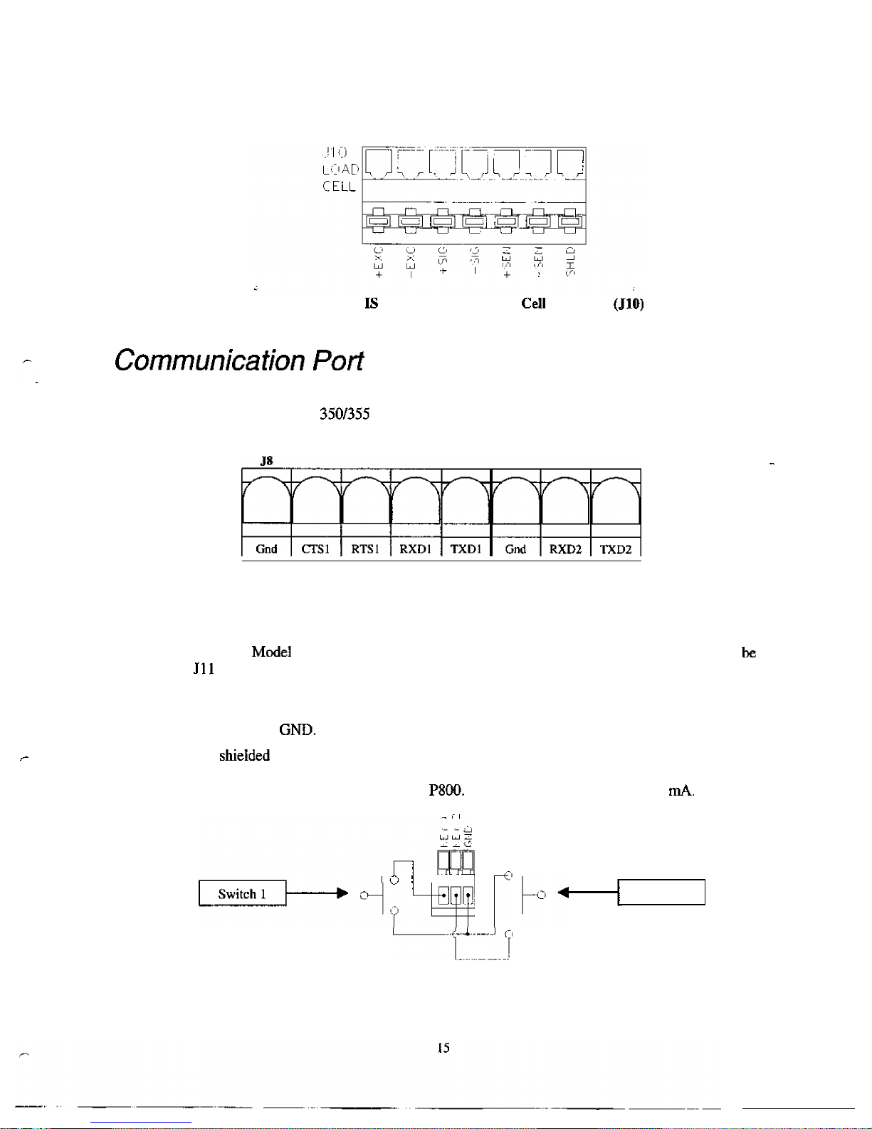
Figure
9:
Model
350
and
Model
355
IS
Load
Connections
The
350
IS
and
355
IS
come
standard
with
two
RS-232
communication
ports.
Every
device
connected
to
a
communication
port
of
the
Model
IS
must
be
approved
for
the
appropriate
hazardous
area
and
entity
parameters.
Refer
to the
diagram
below
for
connections
to
each
communication
port.
Remote
Key
Connections
The
Model
350
IS
and
355
IS
accommodate
two
remote
keys
connections. A remote switch may
connected
to
on
the
main
board
to
provide
remote
activation
of
print,
tare,
or
zero
functions.
The
remote
switch
being
connected
must
be
approved
for
the
appropriate
hazardous
area
and
entity
parameters.
The
connection
for
the
remote switch
input
for
remote
key
lis
between
key
1
and
GND.
Connect
a
second
remote
switch
to
key
2
and
A
two-conductor shieided
cable
between
28
and
20
AWG is
recommended.
The
input
requires a contact
closure
from
a
push-button
switch,
a
'dry'
relay
contact, a photo-eye,
and
a
proximity
sensor or
other
such
device. A closure
initiates the
operation
specified
at
A
closed
switch
will
conduct
2.2
I
I
Switch
2
Figure
10:
Remote
Key
Connection
Page 23
Do
not
apply
an
external
to
remote
key
terminals!
Only
a
contact
closure
is
required
to
activate
the
remote
key
input.
The
open
circuit
voltage
across
the
remote
key pins
is
A
closed
switch
will
conduct
about
0.25
Therefore,
a
low-voltage switch with
gold-plated
contacts
is
recommended.
A
Mercury-wetted
switch
will
also
work
well. A minimum
contact
duration
of
is
required.
Once
invoked,
the
selected
remote
key
operation
will
not
repeat
until
the
contact
is
and
closed
again.
Hazardous
Area
These
options
have
Factory
Mutual
approved
to
operate
in
hazardous
area.
POWER
SUPPLY
(E
XTE
RNA
L
)
Part
number
The
battery is
enclosed
in
a
stainless
steel
case
and
cannot
be
removed
from
the
case.
The
battery
module
is
mounted
on
the
indicator
swivel
bracket.
The
battery
will
operate
approximately
200
continuous
use
with
display
(backlight
off,
1
load
cell and no
options installed)
or
hours
with
the
LED
display
(one
load cell
and
no
options
installed).
-
SWIVEL
BRACKET
Hold the
battery
in
both
hands.
Make
sure
the
connectors
on
the
battery
module
are
facing
the
back
of
the
indicator.
2.
Line
up
the
protrusions
on
the
battery
module
with
the
slide
rails
on
the
swivel
bracket.
3.
Push
the
module
into
the
slide
rails
until
the
drop
into
the
slots in the swivel bracket.
Tighten
the
knobs
to
hold
the
battery
module
in
the
swivel
bracket.
B
A
TTER
Y
C
HARGI
N
G
The
battery
must
be
charged
in
the
safe
area.
Connect
the
battery
to
the battery
charger.
Connect
the
battery
charger
to
AC
power.
Charging
will
take
approximately
3.5
hours.
LOW
The
low
battery
annunciator
will
be
lit
when
the
voltage
reaches
a
low
threshold
and
the
low
battery
message
(Lo
Bat}
is
shown
on
the display
for
seconds
every
15
seconds.
D
EA
D
S
HUTD
O
W
N
The
indicator
will
shutdown
after
five
minutes
of
dead
battery
condition.
POWER
(E
XTERNAL
)
Part
number
The
AC
-
power
supply
is
in
a
stainless
steel
enclosure which
is
remotely
mounted.
Capable
of
powering
up
to
(2)
3501355
IS
indicators
in
gas
Groups
C-G
or
and (1)
3501355
IS
indicator
in
gas
Groups
A
-
G
or
IIC-IIA.
Refer
to
Figure
for
mounting
dimensions.
16
.
Page 24
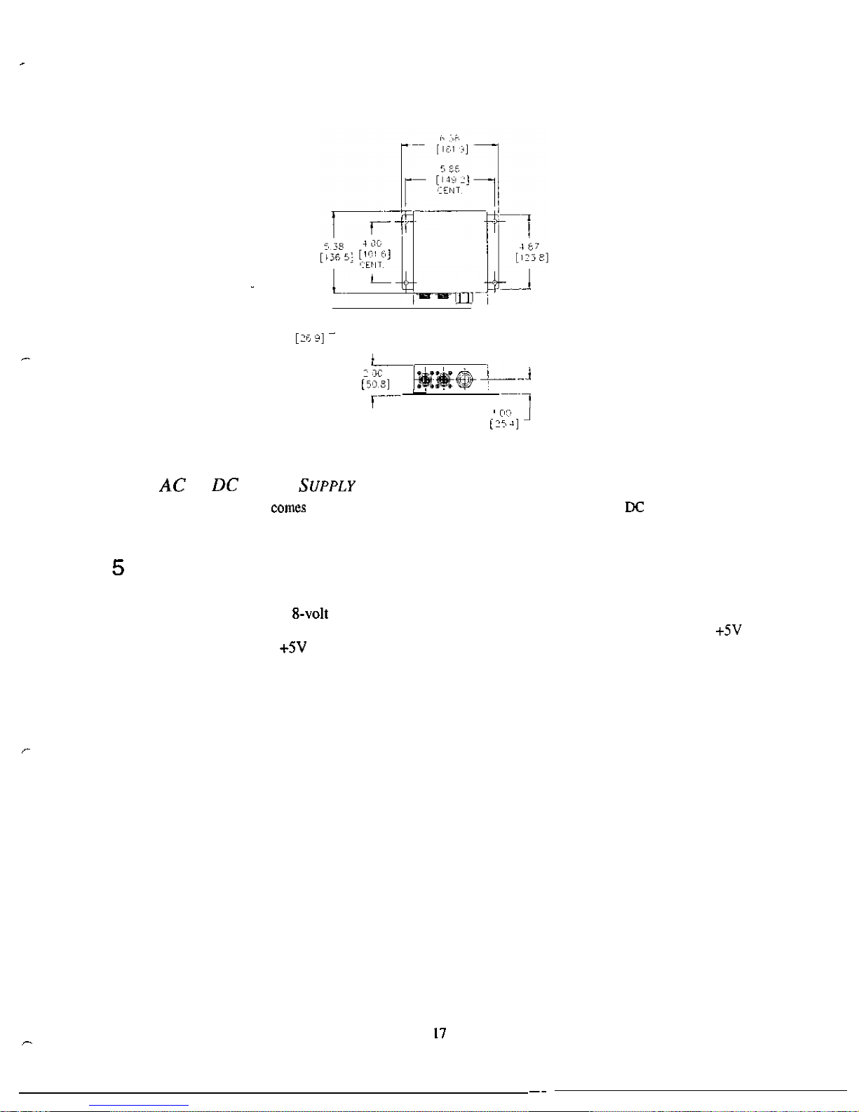
.
,
Figure
11:
AC
to
DC
Power
Supply
Outline
Drawing
TO
P
O
W
E
R
E
XTE
N
SIO
N
CABLE
The
extension
cable
in
either
25'
or
50'
length.
This
is
for
mounting
the
AC
to
converter
away
from
the
indicator.
VOLT
AND
8
VOLT
E
XCITA
T
I
O
N
Two
versions
of
excitation
are
available
for
the
Model
350
IS
and
Model
355 IS.
The
5-volt
excitation
consumes
less
power
than
the
module.
The
5-volt
excitation
is
standard
on
the
main
board.
The
8-volt
excitation
is
on
a
separate
board
which
is
installed
by
the
factory.
The
5-volt
excitation
is
to
OV.
The
8-volt
excitation
is
to
-
3V.
Page 25
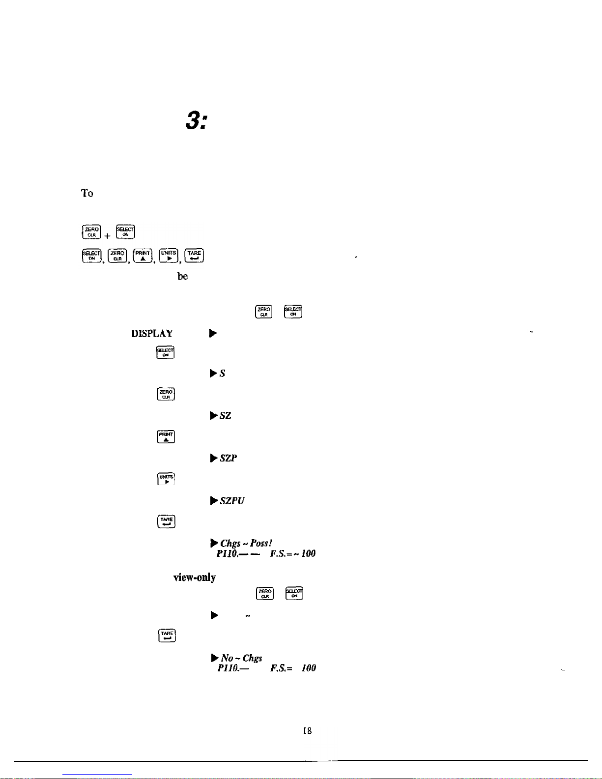
CHAPTER
CONFIGURATION
Entering
the
Setup
Mode
(Model
350
IS)
prevent
accidental
changes
to
the
Indicator
Setup,
a
sequence
of
keystrokes
is
used
to
gain
access
to
the
Setup
Mode:
These
keystrokes
must
made
within
five
seconds,
or
the
indicator
will
return
to
the
Weigh
Mode.
To
access
the
Setup
Mode:
1.
2.
3.
4.
5.
6.
From
the
Weigh
Mode,
press
+
READS
Setup
-
Enter
Code
Press
DISPLAY READS
Press
DISPLAY
READS
Press
DISPLAY
READS
Press
DISPLAY
READS
Press
DISPLAY
READS
-
To
access
Setup
in
a
mode:
1.
From
the
Weigh
Mode,
press
+
DISPLAY
READS
Setup
Enter
Code
2.
Press
DISPLAY READS
-
-
-
Page 26
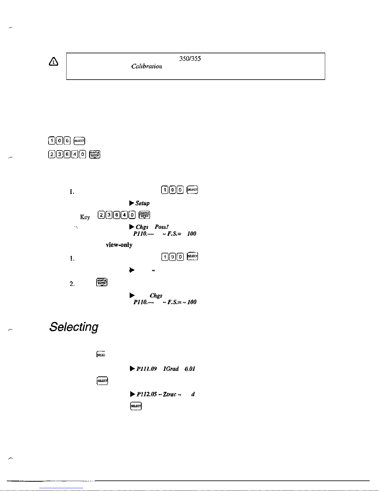
Entering
the
Setup
Mode
(Model
355
IS)
When
exiting
the
Setup
Mode,
the
Model
IS
prompts
whether
to
enter
the
Calibration
Mode.
(See
Chapter
4:
for
Calibration
Mode
procedures).
The
display
will
then
prompt
to
save
any
changes.
To
prevent
accidental
changes
to
the
Indicator
Setup,
a
sequence
of
keystrokes
is
used
to
gain access
to
the
Setup
Made:
These
keystrokes
must
be
made
within
five
seconds,
or
the
indicator
will
return
to
the
Weigh
Mode.
To
access
the
Setup
Mode:
From
the
Weigh
Mode,
key
in
DISPLAY
READS
-
Enter
Code
2.
in
DISPLAY
READS
-
-
-
To
access
Setup
in
a
made:
From
the
Weigh
Mode,
key
in
DISPLAY
READS
Setup
Enter
Code
press
DISPLAY
READS
N
O
-
-
a
Parameter
To
advance
to
the
next
parameter
(Model
350
IS
and
Model
355
IS):
1.
Press
DISPLAY
READS
-
-
2.
Press
DISPLAY
READS
0.5
3.
Continue
pressing
to
advance
through
all
setup
parameters.
To
access
the
previous
parameter
(Model
350
IS):
19
Page 27
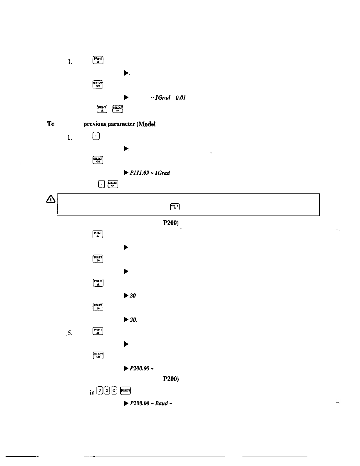
Press
DISPLAY
READS
2.
Press
DISPLAY
READS
P111.09
-
3.
Repeat
to
back
up
one
parameter.
access
the
355
IS):
Press
2.
Press
DISPLAY
READS
DISPLAY
READS
-
0.01
3.
Repeat
to
back
up
one
parameter.
When
accessing
a
parameter,
the
parameter
number
appears
briefly.
The
display
then
toggles
between
the
parameter
name
and
selection.
Pressing
will
again
briefly
display
the
parameter
number.
To
access
a
specific
parameter
(for
example
(Model
350
IS):
1.
2.
3.
4.
6.
Press
DISPLAY
READS
2
Press
to
advance
to
the
next digit.
DISPLAY
READS
2.
Press
DISPLAY
READS
four
times
to
select
the
first
digit.
once
to
select
the
next
digit.
Press
DISPLAY
READS
Press
DISPLAY
READS
200
Press
DISPLAY
READS
Baud
-
9600
to
advance
to
the
next
digit.
once
to
select
the
next
digit.
to
advance
to
the
parameter.
To
access
a
specific
parameter
(for
example
(Model
355
IS):
I.
Key
DISPLAY
READS
9600
20
Page 28
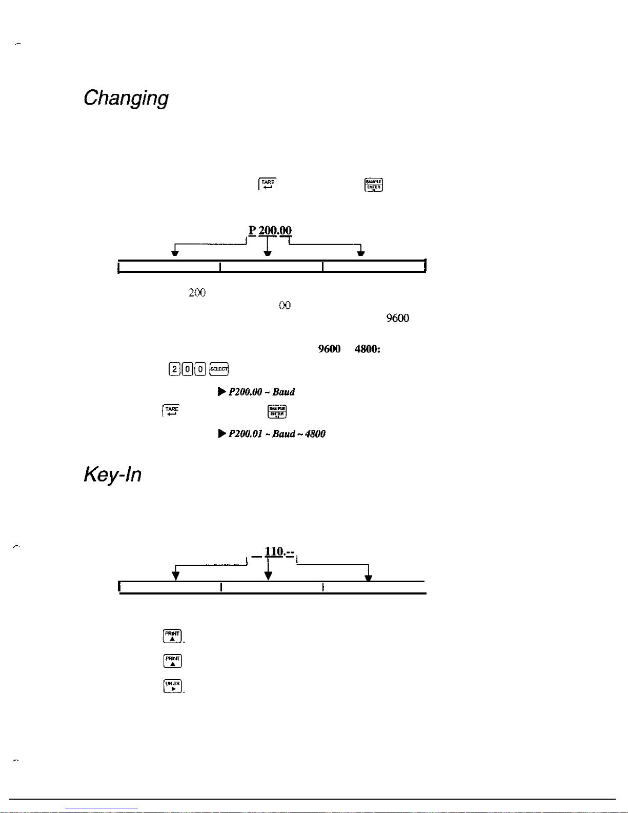
a
Parameter
Value
S
ELECT
ION
P
ARAMETE
R
S
Selection parameters
have
a
predefined
list
of
choices
to
pick
from.
Each
choice
is
numbered
and
corresponds
to
a
certain value.
The
choice
number
is
shown
to
the
right
of
the
decimal
point within
the
parameter
number.
Repeatedly
pressing
selection parameter
cycles
through
the
available choices,
or
you
can
key
in
the
choice
number.
(Model
350
IS)
or
(Model
355
IS)
while
viewing
a
Indicates
Parameter
Parameter
Number
Choice
Number
For
example,
parameter
is
a
selection
parameter that holds the
baud
rate
for
the
serial.
This
is
a
selection
parameter
because a choice
number between
and
06
must
be
used.
Each
choice
number
corresponds
to
a
different
baud
rate.
To
change
the baud
rate
from
the
default
value
of
to
4800,
perform
the
following
steps
from
the
Setup
Mode.
To
change
the
baud
rate
from
the
default
value
of
to
1.
Key
in
DISPLAY
READS
-
9600
2.
Press
(Model
350
IS)
or
(Model
355
IS)
once.
DISPLAY
READS
Parameters
Key-In
Parameters
are
not
limited
to
a
list
of
choices,
although there
may
be
upper
and
lower
value limits.
A
Key-In
Parameter
requires
that
a
numeric
value be
entered
using
the
front
panel
keys.
Key-In
Parameters
are
shown
with
two
hyphens
after
a
decimal
point
within
the
parameter
number.
P
Indicates
Parameter
Parameter
Number
Denotes
“Kev
In”
I
To
enter
a
Key-In
Parameter
(350
IS):
1.
Press
A
decimal
point is
used
to
represent
the
entry
position.
2.
Press until the desired character
appears.
3.
Press
Another decimal point indicates the next entry
position.
4.
Repeat
steps
1
and
2
until your desired entry
value
is
shown.
21
Page 29
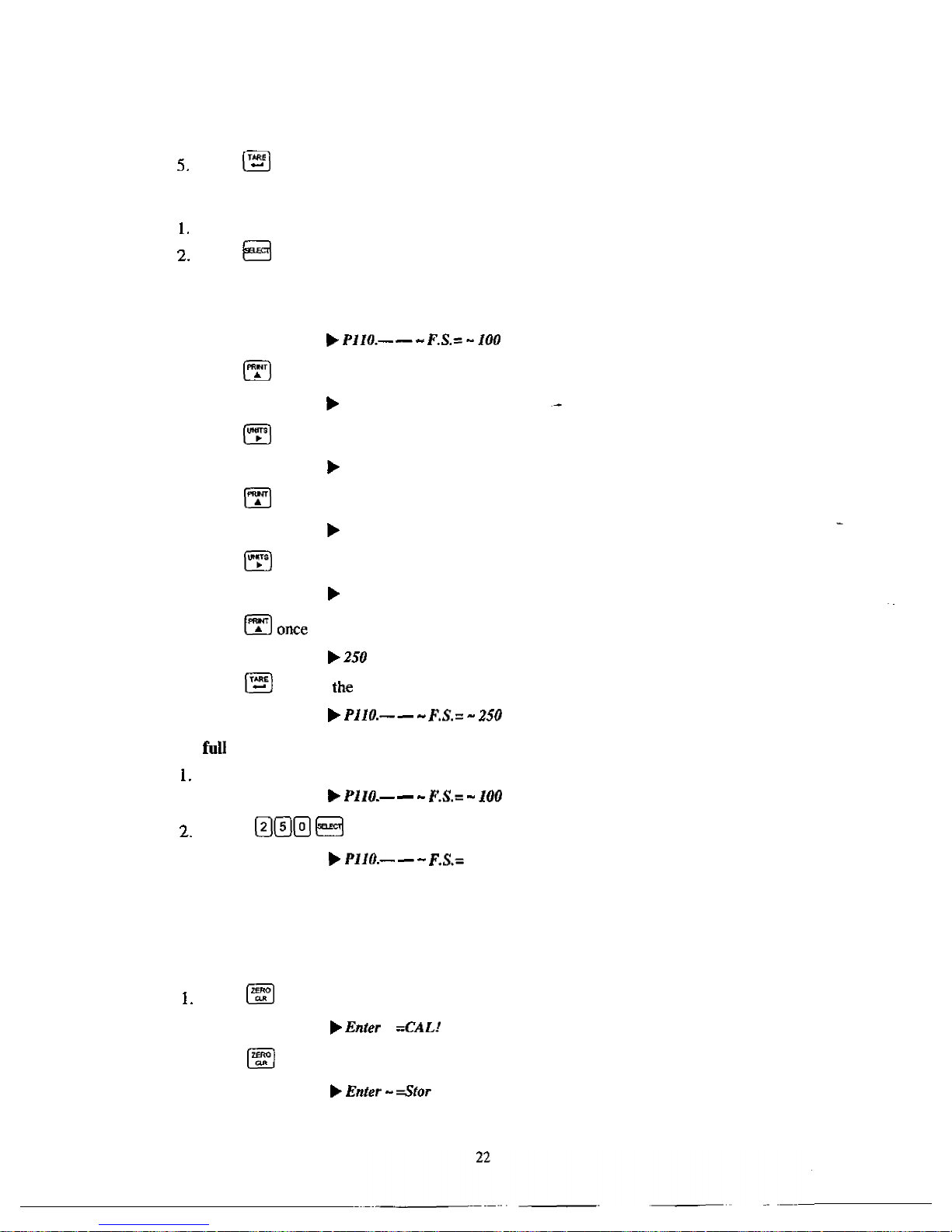
Press
to
enter
your
numerical
value.
To
enter
a
Key-In
Parameter
(355
IS):
Key
in
the
number
by
using
the
numeric
keys.
Press
to
accept
the
entry.
To
setup
a
full
scale
value
of
250
lbs
(350
IS):
1.
2.
3.
4.
5.
6.
7.
Access
the
setup
mode.
Press
four
times
to
select
the
first
digit.
DISPLAY READS
2
Press
to
advance
to
the
next
digit.
DISPLAY
READS
2.
Press
six
times
to
select
the
next
digit.
DISPLAY
READS
25
Press
to
advance
to
the
next
digit.
DISPLAY
READS
25.
Press
to
select
the
next
digit.
DISPLAY READS
Press
to
enter
value.
DISPLAY
READS
DISPLAY
READS
To
setup
a
scale
value
of
250
lbs
(355
IS):
Access
the
setup
mode.
Key
in
to
accept
the
entry.
DISPLAY READS
DISPLAY
READS
-
250
Saving
Parameters
To
exit
the
Setup
Mode
and
save
changes
(350
IS):
Press
to
begin
exiting
Setup
Mode.
DISPLAY
READS
-
2.
Press
to
bypass
Calibration
Mode.
DISPLAY
READS
Page 30
3.
4.
Press
to
save
setup
changes.
DISPLAY
READS
Enter
-
Press
to
complete
exit.
DISPLAY
READS
To
exit
the
Setup
Mode
and
save
changes
IS):
Press
begin exiting
Setup
Mode.
DISPLAY
READS
-
2.
Press
to
bypass
Calibration
Mode.
DISPLAY
READS
Enter
-
3.
Press
to
save
setup
changes.
DISPLAY
READS
Enter
-
press
to
complete
exit.
DISPLAY
READS
0.00
To
exit
the
Setup
Mode
from
the
view-only
mode
(350
IS):
Press
to
begin
exiting
Setup
DISPLAY
READS
Enter
=End
2.
Press
to
exit.
DISPLAY
READS
0.00
To
the
Setup
Mode
without
saving changes
(350
IS):
1.
Press
to
begin
exiting
Setup
Mode.
DISPLAY
READS
Enter
2.
Press
to
bypass
Calibration
Mode.
DISPLAY
READS
Enter
-
3.
Press
to
exit
saving
changes.
DISPLAY
READS
-
4.
Press
to
undo
changes.
DISPLAY
READS
Enter
-
5.
Press
to
complete
exit.
DISPLAY
READS
23
Page 31

To
exit
the
Setup
Mode
without
saving
changes
(355
IS):
Press
to
begin
exiting Setup
Mode.
DISPLAY
READS
Enter
-
2.
Press
to
bypass
Calibration
Mode.
DISPLAY
READS
Enter
-
3.
Press
to
exit
saving
changes.
DISPLAY
READS
Enter
-
4.
Press
to
undo
changes.
DISPLAY
READS
-
Press
to
complete
exit.
DISPLAY
READS
Factory
Parameter
65001
and
65002
are
available
to
the
Model
350
IS
to
factory
settings.
Parameter
reset
parameters
including
the
calibration,
while
parameter
65002
resets
all
parameters
accept
the
calibration.
Return
to
factory
default
(350
IS):
Access
the
setup
mode.
See
page
18
for
details.
in
or
DISPLAY
READS
3.
Press
once.
DISPLAY
READS
Are
4.
once.
DISPLAY
READS
Setup
Press
Return
to
factory
default
(355
IS):
1.
Key
in
DISPLAY
READS
Press
once.
DISPLAY
READS
Are
24
Page 32

List
of
Parameters
The
Model
350
IS
and
355
IS
have
several
parameters
that
can
be
configured
to
your
specific
application.
Below
is
a
table
of
the
available
parameters.
Also
refer
to
page
27
for
explanations
of
each
parameter.
Table
Parameter
Map
Parameter
s
a
y
Number
25
Page 33

.
-
(3
Selections)
Off
Disable
Enable I Disable
Disable
Enable
Disable
(Toggle)
1.2
hours
hour
12
hour
or
International
Disable
Enable
Disable
(5
Selections)
Disable
I
Disable
SLOP
D
i
a
I
e
Enable
Disable
30
Parameter
I
Function
Function
Function
Remote
Button
Function
Remote
Button
Comm
1
Motion
30
31
31
31
Print
Transmission
29
Comm
2
Baud
Rate
28
Comm
2
Data
Bits
28
Comm
2
Parity
29
Comm
2
Stop
Bits
29
Comm 2
Handshake
29
(5
Selections)
None
None
-
None None
-
I
Comm
2
Transmit
29
Comm
2
Motion
29
Print
Transmission
29
OIML
Enforce
30
DispIay
Function
30
NTEP
Enforce
Function
Custom
Transmit
355
Target
Key
355
Stop
Key
26
Page 34

,
-
P
ARAMETE
R
M
A
P
P112
P114
P116
P117
Full
Scale
Value
(Key
in)
Denotes the full
scale
capacity.
This
value
should
not
exceed
the
rated
capacity
of
the weighing
device.
Division
Size
(Selection)
Indicates the count-by
and
decimal point. Pressing
(Model
350
IS)
or
(Model
IS)
will
automatically select
the
choice
closest
to
divisions
without
exceeding
divisions.
Zero
Track
Aperture
(Selection)
Set
in
terms
of
number
of
divisions.
Zero
tracking eliminates
small
weight
deviations
at
or
near
zero.
Weight deviations within
the
selected
window
that
have
been
stable
for
more
than one second
are
tracked
off,
maintaining
a
gross
or
net
zero
condition.
The
sum
of
weight
values
zeroed
with
auto
zero
tracking
and
cannot
the
allowable
zero
range
To
determine
the
proper
setting
in
a
counting application, divide
the
weight
of
the
smallest
product
counted
by
the
division
size
Zero
Track
should
be
set to
0
(off)
for
most
setpoint filling
operations.
This
prevents tracking
off
any
product trickle
at
the
start
of
a
fill
process.
Stability
(Selection)
Stability is
defined
as
weight
fluctuations
within
an
aperture that
can
be
regarded
as
being a stable
weight.
Deviations
outside
this
aperture
are
considered
motion,
and
the
motion
annunciator
on
the
front
panel
will
light accordingly.
Once
the
settles
within
the
stability
aperture,
the
indicator
will wait
one
second
before
the
indicator
is
considered
stable.
Print operations
configured
as
motion
delayed
will
not
send the specified
data
until
the
weight
reflects
a
stable
reading
as
designated
by
this setting.
Certain
setpoint operations
are
also
considered
motion
delayed
and
wilI
not
change states until a no-motion condition exists.
Filter
{Selection)
Sets the indicator
response
time
in
terms
of
seconds. Filtering determines
how
quickly
the
indicator
will respond
to
changing input signals.
A
Iow
filter
setting
speeds
the response, a higher filter setting
will
‘dampen’
the
response.
Filtering
is
used
to
filter out
weight
fluctuations
caused
by
outside
sources,
such
as
vibrations or
air
currents.
Rate
(Selection)
Specifies
how
often the
display
is
updated
with
new
data.
For
example,
if
0.05
is
selected,
the
controller will
write
data
to
the display
every
time
an
is
made.
Since
the
converter
updates
every
0.05
selections
from
0.05
to
20.0
seconds
are
available.
This
parameter
also
affects
the
transmission
rate
for
continuous
transmit.
Actual transmission intervals
are
dependent upon
system
setup.
Zero
Range
(Selec
27
Page 35

Specifies
how
many
divisions
can
be
zeroed
in
terms
of
a
percentage
of
full
scale
(PI
10).
The
sum
of
weight values
zeroed
through the
key
and
auto
zero
tracking
cannot
exceed
this
range.
A
zero
range
of
5%
is
commonly
used
with large
tank
scales
to avoid
accidental
zeroing of
a
full
or
partially
full
tank.
Note
that if a setpoint
activation
method is
set
to
disabling
Auto
Tare
will
also
disable
the
activation
of
that
setpoint.
Units
(Toggle)
Set
default
units
to
or
The
indicator
must
use
the
default
units
during
calibration
procedures
(see
Chapter
4).
The
default units
are
the
displayed
units
upon
indicator
power-up.
Button
(Toggle)
When
enabled,
this
parameter
will
When
disabled,
the
indicator will
show
only the
calibration
units
as
determined
by
to
toggle
the
units
between
and
‘kg’
Unit
This
parameter
allow
the
choice
of
three
(ounces,
grams
or
lb
that
may
accessed with
the
selected
if
is
enabled.
The
third
unit
be
identified
by
an
annunciator
on
the
display. This
unit
selection
is
not
legal
for
trade.
key.
Only
one
unit
will
be
avaiiable
at
a
time.
The
third
unit
can
only
be
Tare
Save
(Toggle}
Enabling
Tare
Save
allows
the
indicator
to
retain
the
tare
value
in
the
event
of
power
loss.
The
correct
net
weight
is
restored
upon
power-up.
Auto
Tare
(Toggle)
When
enabled,
pressing
will
wait
for
a
no-motion
condition
and
then
bring
the
scale
to
a
net
zero
reading. Disabling will prevent
keypad
tare
operations.
P169
Auto
Tare
Clear
(Toggle)
Enabling
this
feature
will
cause
the
current
tare
to
be
cleared to
zero
every
time the indicator
stabilizes within
graduations
of
gross
zero
P171
Analog
(Toggle)
Future
use.
P179
Count
(Toggle)
When
enabled,
the
quantity
mode
becomes
accessible via
the
key.
The
quantity
mode
is
identified
by
the
illumination
of
the
QTY
annunciator.
Baud
(Comm
1)
(Selection)
Set
the
desired
baud
rate
for
the
communication
port.
150 - 1
f5R
Data
Bits
(Comm
1)
(Toggle)
Page 36

Select
7
or
8
data
bits
for
the
transmission.
Choice
Number
P203
P204
P210
P221
P222
P223
P224
10.0
I
P210.02
Parity
(Comm
(Selection)
Select
Odd,
Even
or
None
for
the
transmission
parity.
All
transmissions
disabled.
Press
Sends
transmissions
continuously.
Sends
transmission
with
[PRINT]
key.
Stop
Bits
(Comm
1)
(Toggle)
Select
I
or
2
stop
bits
for
communication
port
transmissions.
Send
transmission
after
weight
is
reached
below
0.1
of
P.S.
io
reset
for
next
transmission.
P210.03
Cycle
and
motion
ceases.
Must
return
display
value
Comm
Handshake
(Comm
1)
(Selection)
Select
from
None,
Hardware
or
Both.
Send
(Comm
(Selection)
Transmission
Send options:
Send
Stability
(Comm
1)
(Toggle)
Send
Stability
will
delay
any
transmissions until
a
no-motion
condition
exists.
Transmit
Selection
(Comm
1)
Select
desired
print
output
(1 - 14
or
custom).
The
transmission
will
be
initiated
by
the selected
print
operation
and
or
the
Remote
Key
selection
See
page
32
for
details
on
preset
formats
or
page
34
for
details
on
custom
transmit.
Baud
(Comm
2)
(Selection)
Set
the
desired
baud
rate
for
the
communication
port.
150
-
Data
Bits
(Comm
(Toggle)
Select
7
or
8
data
bits
for the
transmission.
Parity
(Comm
2)
(Selection)
Select
Odd,
Even
or
None
for
the
transmission
parity.
Stop
Bits
(Comm
2)
(Toggle)
Select
I
or 2 stop
bits
for
communication
port
transmissions.
Comm
Handshake
(Comm
2)
(Selection)
Select
from
Nun
and
Send
(Comm
2)
(Selection)
Transmission
Send
options:
29
Page 37

P232
P233
P423
Choice
Number
P230.00
P230.01
P
2
3
0.0
2
P230.03
Selection
Press
Sends
transmissions
continuously.
Cycle
All
transmissions
Sends
transmission
with
[PRINT]
key.
Send
single
transmission
after
weight
is
reached
and
ceases.
Must
retum
display
value
below
of
F.S.
to
reset
for
transmission.
Send
Stability
(Comm
(Toggle)
Enabling
Send
Stability
will
delay
any
transmissions until
a
no-mo
condition
exists.
Parameter
P420.00
Transmit
Selection
(Comm
(Selection)
Select
desired
print
output
(1
14
or
custom).
The
transmission will
be
initiated
by
the
selected
print
operation
and
or
the
Remote
Key
selection
See
page
32
for
details
on
preset
formats
or
page
34
for
details
on
custom transmit.
Choice
off
Shuts
off
the
display.
Euro
(Toggle)
Enable
OIML
legal-for-trade restrictions
(see
Chapter
5:
Fur
Trade).
P420.02
(Selection)
Select display
option.
Choose
from
On,
The
auto
setting
helps
conserve
power
for
extended
battery
When
the
indicator
display
is
off,
the
load
are
still
powered.
If
P420
is
set
to
selection
you
can
on
the display
by
holding
down
the
key
upon
power
up.
This
does
not
set
P420
to
On;
it
only
temporarily
turns
on the
VFD
display
in
order
to
you
to
see
what
you
are
entering.
changing
weight
6
divisions
the
display.
NOTE:
The
display
will
back
on
if
data
is
via
the
RS-232
Port.
P420.01
On
Normal
display
operation.
I
Shuts
off
the
when
weight
has
stabilized
6
divisions
for
5
minutes.
Back
Light
Toggle the
backlight
on
a
IS
LCD
Legal
For
Trade
(Toggle)
Enable
NTEP
legal-for-trade
restrictions.
See
5:
Legal
For
Trade.
(toggle)
Enables
or
disables
the
time
and
date
feature.
If
enabled
the
time
and
date
will
be
accessible
from
the
weigh
mode
with
the
key.
See
page
63
for
instructions
on
how
to
change
the
time
andlor
date. Note:
if
disabled
will
not
be
accessible,
however,
their
current
settings will
be
retained
for
future
use.
Hours
(toggle)
Determines the
TIME
format
style,
12
hour
or
24
hour.
If
in
12
hour
mode
the
right
most
decimal
point
on
the
LED
display
will
become
the
PM
indicator. Note:
The
time
must
be
entered
as
military
time.
If
the
mode
is
set
for
12
hour,
the time
will
be
converted
to
a
12
hour
clock.
Page 38

Style
(toggle)
Determines
the
DATE
format
style,
U.S.A.
or
If
set
for
the
date
will
resemble
01/26/01.
If
set
for
international,
the
date
will
resemble
Select
(toggle)
Allows
the time
and
date
to
be
viewed
with
the
key
from
the weigh
mode.
The
weight
will
continue
to
be
updated
when
viewing the time
or
date.
The
time will
formatted
as
defined
by
P503
and
the
date
will
be
as
defined
by
Remote
Key
I
Operation
(Selection)
Select function
for
Remote
Key
closure.
Choose
from
Print,
Tare,
Zero
or
If
a
setpoint
is
configured
to
use
the remote
key
as
an
activation method, then the
is
over
-
ridden.
The
Remote
Key Operation
section
on
page
66
details
the
remote
key
operation.
See
Remote
Key
Connection
on
page
15
for
remote
key
electrical connections.
Remote
Key
2
Operation
(Selection)
Select function
for
Remote
Key
closure.
Choose
from
Print,
Tare,
or
If
a
setpoint is
to
use
the
remote
key
as
an
activation
method,
then
the
setting
is
over
-
ridden.
The
Remote
Key
Operation
section
on
page
66
details the
remote
key
operation.
See
Remote
Key
on
page
15
for
remote
key
electrical
connections.
Custom
Transmit
A
custom
transmit
is
a
userdefined string
of
data
that
can
be
sent to
the
serial
port.
Parameter
is
the
beginning
of
the
custom
transmit table
and
must
be
enabled
for
transmit
by
selecting
at
Parameters
use
three
bytes
of
memory;
ASCII
characters
and
control
codes
use
one byte.
See
for
available
memory.
The
custom transmit
cannot
viewed
or
altered
from
the
indicator.
A
custom transmit
must
be
entered
via
the serial
port.
See
Custom
Transmit
Setup
on
page32
for
details
on
designing
and
loading
a
custom
transmit.
355
Target
Key
(Toggle)
Altows
a
target
value
to
be
entered
or
viewed.
Sending
a
using
a
device
such
as
a
computer
is
equivalent to
pressing
the
Target
key.
355
Stop
Key
(Toggle)
Enable
or
disable
the
use
of
the stop
key
from
the
355
keypad.
Pressing the
stop
key
in
the
gross,
net
or
quantity
modes
with
cause
all
setpoints
to
deactivate
and
pause.
Sending
a
using
a
serial device
such
as a computer
is
equivalent
to
pressing
the
Stop
key.
355
Start
Key
(Toggle)
Enable
or
disable
the
use
of
the start
key
from
the
355
keypad.
Pressing the
Start
key
in
the weigh
with setpoints
enabled
causes
a
paused
setpoint
operation
to
be
resumed.
In
setpoint
modes
other
than checkweighing,
the
Start
key
performs
the
same
operation
as
a
remote
key.
Sending
a
using
a
serial
device
such
as
a
computer
is
equivalent
to
pressing
the
Start
key.
355
Restart
Mode
(Toggle)
Determines the method
in
which the checkweighing
mode
Auto
will
restart
after
retum to
zero
or
Manual
will restart
by
pressing
the
function
is
disabled
and
parameter
will
no&
appear.
key.
Stop
is
disabled,
this
31
Page 39

Setpoint
Annunciators
(Toggle)
or
disables
the
setpoint
annunciators
to
the
left
of
the
main
7-segment
display.
Disabling
the
setpoint
annunciators
may
be
desired
when
the
bargraph
is
enabled
while
using
an
display.
See
Bargraph
on
page
40.
Setpoint
Bargraph
(Toggle)
Enables
or
disables
the
bargraph
display
on
the
LCD
version
of
the
Model
3501355
display.
This
setup
parameter
only
appears
if
an
display
is
installed.
See
Bargraph
on
page
40.
Setpoint
Bargraph
Low-Limit
Percentage
(Key
in)
Controls
the
"
bargraph
low-limit
percentage
"
value
for
determining
the
of
each
segment
of
the
bar
This
only
appears
if
an
LCD
display
is
installed.
See
Bargraph
on
page
Setpoint
Operation
(Selection)
Sets
the
desired
Setpoint
operation.
Choose
between
None,
ChecP,
Fill,
Batch,
Discharge,
Both,
ChecA
or
Independent.
See
General
Setpoint
on
page
complete
details
on
setpoint
setup
and
operation.
Preset
Transmit
The
Model
350
IS
and
Model
355
IS
provide
14
preset
formats
for
printing
tickets
or
sending
data
to
a
computer.
Only
one
format
or
custom
transmit
may
be
enabled
at
a
time.
Choice
0
Custom
Transmit:
User-defined
serial
data
string
(see
Custom
Transmit
Setup
on
page
32).
Choice 1
GSE
Standard
.
Tare
Net
am
Choice
2
Count:
am
QTY
Tare
.
Net
(NOTE:
The
time
and
date
will
only
be
printed
in
choice
I
and
2
is
enabled).
Choice
3
Clone):
Where:
is
a
single
control
code,
decimal
value
of
2.
is
characters,
character
is
either
minus
sign
or
a
space,
padded
with
with
an
embedded
decimal
point.
.
is
a
single
or
'K'
character
to
indicate
lb
or
units.
is a single
'G
character
to
indicate
or
net
data.
is
'M'
(motion),
or
space
otherwise.
is
a
single
control
code
(carriage
return),
decimal
value
of
is
a
single
control
(line
feed),
decimal
value
of
32
Page 40

Choice
4:
Choice 5:
Choice
6:
Choice
7:
Choice
9:
Choice
10:
Displayed
Choice
11:
Displayed
Choice
12:
Use choice
12
to
send
to
a
remote
display
that
is
set
to
text
mode
and
a
terminator.
Choice
14
(Simulates
NCI
Setpoint
Status
Transmitting
the
setpoint
status
will
reflect
the
current
state
of
all
the
setpoints,
regardless
of
which
setpoint
operation
is
configured.
The
status
can
be
read
as
a
single
ASCII
numeric
character
a
Hex
value
37h)
or
a
binary
bit
comparison.
Status
is
preceded
a
and
an
The
preceding
data
stream
format
is
for
fixed
transmissions
of
as
specified
above.
This
is
not
associated
with
the
custom
transmission
of
parameter
P96.
33
Page 41

Custom
Transmit
The
serial
output
of
the
Model
IS
can
be
configured
for
a
custom
application
such
as
a
remote
display
format,
customized
computer
program
format,
or
a
ticket
format.
custom
transmit
must
be
designed
in
a
computer-transmittable
ASCII
text
file.
The
custom
transmit
can
only
be
loaded
into
the
indicator
through
the
serial
port.
must
be
set
to 0 to
select
the
custom
transmit
format
for
transmission.
E
LEM
ENT
S
OF A CUSTOM
T
R
A
NSMIT
Parameters,
ASCII
text,
and
control
codes
are
the
of
a
custom
transmit.
Parameters
Certain
parameters related
to
weight,
quantity,
setpoints
and
status
can
be
sent
out
of
the
comm
port.
Gross
Weight,
Target
and
Quantity
are
examples
of
printable
parameters.
ASCII
Text
ASCII:
text
can
entered
into
a
custom
transmit
to
provide
further
detail
of
a
transaction.
and
are
examples
of
ASCII
text.
Control
Codes
You
can
custom
transmit
ASCII
control
codes
to
a
printing
device.
(carriage
return)
and
(form
feed)
are
examples
of
control
codes.
WRITING
A
CUSTOM
TRANSMIT
TEXT
FILE
Any
text editor
may
be
used
to
construct
a
custom
transmit
Wordpad,
etc.),
but
you
must
save
the
custom
transmit
as
a
text
file.
Instructions
can
also
be
sent
keystroke
by
keystroke
from
a
communications
program.
To
do
so,
ignore
the
Model
3501355
IS
display
and
enter
the
characters
in
the
correct
order.
Figure
shows
a
custom
transmit written
in
Wordpad.
A
CCESS
I
N
G
SETUP
AND
CLEARING
E
X
ISTIN
G
CUSTOM
TRANSMIT
Every
custom
transmit
must
start
with:
I
34
.
Page 42

This
accesses
the
Setup
Mode
at
the
end
of
the
existing
transmit
and
then
clears
the
transmit
so
that
a
new
one
may
be
entered.
Gross,
Tare
and
Net
Parameters
Exit
Setup
Mode
and
Save
Changes
Figure
Transmit
File
E
N
TERIN
G
ASCII
T
E
X
T
ASCII
text
is
defined
as
printable
characters,
including
alpha-numerics
as
well
as
punctuation
symbols.
See
Table
4
for
a
complete
listing
of
ASCII
characters.
ASCII
text
can
be
entered
directly
into
a
custom
transmit with
a
(enter
command).
For
example,
Joe's
Fertilizer
E
N
TER
I
N
G
CONTROL
CODES
Some
ASCII
characters
are
known
as
control
codes,
characters
that
instruct
a
printing
device
to
perform
certain
functions.
For
example,
a
carriage
return
forces
a
printer
to
move
the
print
head
to
the
left-most
position
of
the
current
line. A line
feed
forces
the
print
head
to
move
down
one
line.
Enter control
codes
with
a
decimal
point,
a
ASCII
code,
and
a
For
example,
Page 43

Table
2:
ASCII
HEXADECIMAL
CONVERSION
CHART
CHAR
12
29
43
5D
75
117
76
77
NAK
49
ti7363
c
123
124
Most
printers
require
a
return
line
feed
to
print
preceding
data
and
avoid
leaving
data
in
the
printer
buffer.
See
page
35
for
a
list
of
ASCII
codes.
36
Page 44

P
A
RAM
ETE
R
N
U
M
BER
S
The
following
sequence
enters
parameters
into
a
custom
transmit:
the
parameter
number,
,
a
format
code,
and
then
with
no
intervening
spaces.
Initiates
Parameter
Entry
Format Enters
Format
Parameter
Enters
Parameter
(Table
Format
Entry
(Table
Entry
Number
and
Initiates
Choice
and
Ends
-
-
%e
Table
3:
Custom
Transmit
Parameter
Selection
Numbers
Parameter
Name
I
Parameter
Sample
Print
Output
The
default
format
code
for
all
parameters
is
0.
This
prints
all
numeric
data with 8 characters,
right
justified,
left
spaces
filled.,
the
units
(if
applicable)
and
the
parameter
name.
The
format
choices
for
all
parameters
(except
Stability
Status
and
Setpoint
Status)
are
shown
in
Table
4.
Table
4:
Custom
Transmit
Format
Page 45

If
a
combination
of
format
choices
is
required,
add
the
choice
numbers
together
and
enter
their
sum
as
the
format
code.
For
example,
to
print
the
net
weight
without
the
name
(Net)
or
units
(Ib)
and
to
print
it
minimum
width:
NOTE:
Only
one
of
the
choices
may
be
used
at
one
time.
163
Use
the
sum
of
the
choice
selections:
Minimum
possible
width.
Do
NOT
print
parameter
units.
Do
parameter
name.
SETUP
M
O
D
E
AND
CHANGES
Each
custom
transmit
file
must
end
with:
This
exits
the
Setup
Mode,
bypasses
the
calibration
procedure
and
saves
the
indicator
configuration
file.
The
counting
parameter
must
be
enabled
before
quantity
mode
is
available.
Refer
to
page
28
for
details
on
the
counting
parameter
and
page
18
to
enter
the
setup mode,
make
changes
and
save
the
change.
To
sample
selectable
fixed
counts
(350
IS):
From
the
Weigh
Press
DISPLAY
READS
to
view
the
current
net
weight.
2.
Press
until
the
QTY
annunciator
is
lit.
The
display
may
show
do
there
is
no
DISPLAY
READS
Press
to
perform
auto-tare.
The
scale
prompts
to
add
10
pieces.
DISPLAY
READS
Add
-
38
Page 46

Press
to
toggle
sample
amounts
between
5,
IO,
20,
50
and
DISPLAY
READS
Add - 20
5.
Add
the
pieces
to
be
sampled
and
press
to
sample
and
display
the
current
quantity.
DISPLAY
READS
20
To
sample
using
fixed
counts
(355
IS):
Press
to
perform
an
auto-tare.
The
scale
prompts
to
add
pieces.
DISPLAY
READS
Add
2.
Press
to
toggle
sample
amounts
between
5,
50
and
DISPLAY
READS
Add
-
3.
Add
the
pieces
to
be
sampled
and
press
to
sample
and
display
the
current
quantity.
DISPLAY
READS
To
sample
using
variable
counts
(350
IS):
1.
From
the
Weigh
Mode,
Press
to
view
the
current
net
weight.
DISPLAY
READS
1.05
2.
Press
to
view
the
current
DISPLAY
READS
3.
Press
to
perform
an
auto-tare.
The
prompts
to
add
10
pieces.
DISPLAY
READS
Add
-
4.
Add
pieces,
key
in
36,
then
press
to
sample
as
36
pieces
and
display
the current
quantity.
DISPLAY
READS
36
To
sample
using
variable
counts
(355
IS):
Press
to
perform
an
auto-tare.
The
scale
prompts
to
add
10
pieces.
DISPLAY
READS
Add
-
LO
2.
Add
pieces,
key
in
36,
then
press
to
sample
as
36
pieces
and
display
the
current
quantity.
DISPLAY
36
Page 47

Setpoint
Setup
Activation
Method
(355
The
Model
IS
has
several pre-programmed
scale
setpoint applications available
at
P5
Various
related
setpoint
parameters
may
appear
according
to
which
of
the
standard
programs
is
chosen.
Table
5
describes
the
available
setpoint
operations.
Description
activates
the setpoint.
It
waits
for
a
no-motion
condition.
The
appropriate
setpoint
Table
5:
Setpoint
Operations
55
Absolute
check-weighing.
tolerances
are
based
on
discrete
values.
100.06
Independent
Setpoints.
Activation
based
on
specific
target
values.
I
Includes selectable
conditions.
PS100.07
59
Target
Deviation
check-weighing.
tolerances
deviated
from
target
weight.
P5
Each
program
utilizes
the
three
annunciators
located
to
the
left
of
the
main
display
to
give
a
visual
status
of
the
setpoint. A setpoint
option
bard
may
be
installed
to
allow
control
of
an
external
device
[see
Card
Connections
on
page
)
.
A
C
TIV
A
T
ION
METHODS
(G
E
NER
A
L
)
40
Page 48

Activation
Method
Description
Target
=
lbs.
activates
the
setpoint.
It
waits
for
a
no-motion
condition,
then
tares
scale
to
net
zero.
Tare
Operation
The
appropriate
setpoint is
then
activated.
Desired
final
weight.
The
[REMOTE
KEY]
closure activates
the
The
remote
key
function
(assigned
at
is
over-ridden.
Remote
Keys
Auto-S
tart
Automatically
activates
the
setpoint
after
motion
ceases.
P
R
E
-
A
CTS
(G
ENE
RAL
)
Pre-Acts
are
control
actions
prior
to reaching a desired target value.
Necessary
to
prevent
over-filling
due
to
product
flow
rate,
relay
and
valve
response
time
and
product suspension,
Pre-Acts
compensate
for
other
system
variables
affect
how
much
more
product
reaches
the
weighing
device
after
the
indicator
has
deactivated
a
setpoint.
Pre-act
1
Used
in
dual-speed
applications, pre-act 1 specifies
when
the
3501355
IS
should
switch
from fast-fill to
slow
-
fill,
allowing
the
system to
perform
the bulk
of
a
filling
operation
as
quickly
as
possible
before
switching
to
more
manageable
dribble
mode
for
final cutoff.
When
using a single-speed
device,
set
pre-act
1
too.
Pre-act
2
Specifies
the
weight where
the
final
cutoff
should occur,
enabling
the
3501355
IS
to
compensate
for
a
dispensing control’s
closure
time
and
account
for
free-fall
material.
Free-fall
is
the
amount
of
product
that
has
passed
the
point
of
the
dispensing
control
yet
not yet
reached
the
weighing
device.
Re-act
values
are
entered
in
terms
of
the
amount
of
product
that
would
over-fill
or
‘how
early’
to
close
the
control
device.
For
instance,
after
repeated
tests,
a
consistently over-fills
by
lbs.
This
is
the
value
that
should
be
entered
the
pre-act.
The
IS would
then
deactivate the setpoint
lbs.
less
than the
desired
final
target
value.
Parameter
setting
Actual
Cutoff
Comments
3
2
=
-
399.5
Final
fill
valve
closes
at
lbs.
L
EAR
N
F
E
A
T
U
R
E
(G
ENE
RAL
)
The
3501355
IS
can
‘lea”
optimal
pre-act values.
When
enabled,
the
learn
feature will
automatically
adjust
the
final
cutoff
value
based
on
an
analysis
of
the
five
previous fills, helping
achieve
a
final
target
by
compensating
for
product
viscosity,
changes
in
plant air
pressures,
sticky
valves,
etc.
For
each
cycle,
the
prior
five
final
weights
analyzed
and
a
new
pre-act
value
is
calculated.
P
A
U
S
E
F
E
A
TUR
E
(G
ENE
R
A
L
)
The
3501355
IS
can
pause
setpoint operations.
This
is
useful
to
provide
a
pause
for
operator
breaks,
mechanical
adjustments,
41
Page 49

Pause
Setpoints
on
the
Model
350
IS
When
Pause
deactivates
all
setpoiots.
The
display
will
show:
Pressing
abort
the
current
cycle;
any
other
keypress
will
resume
the
The
Pause
feature
has
four
settings:
will
Pause
Action
I
Pause
feature
disabled.
Remote
Key
Current
cycle
paused
-
all
setpoints
deactivated.
Keypad
Current
cycle
paused
-
all
setpoints
deactivated.
Remote
Key
Contact
Closure
IS
Key
Press
OR
Remote
Key
Contact
Closure
Both
Current
cycle
-
all
setpoints
deactivated.
Pause
Setpoints
on
the
355
IS
When
invoked,
Pause
deactivates
all setpoints.
Pressing
the
key
will
pause
the
setpoints.
The
display
will
show:
Abort
-
Stop
Abort.
Pressing the
key
again will
abort
the
setpoints.
Pressing
the
key
resume
all setpoints.
In
the
independent setpoint
mode,
the
setpoints
will remain deactive until
the
key
is
pressed.
CHANGING
T
A
R
G
E
T
S
FROM
THE
WEIGH
M
O
D
E
(G
ENE
R
A
L
)
When
a
setpoint operation
is
configured
from
the
Setup
Mode,
certain
parameters
are
made
available
in
the
Weigh
Mode.
Pressing
cycles
through
available
modes
(Gross,
Net,
Quantity,
Targ
1,
etc.).
When
viewing a setpoint-related
parameter
from
the
Weigh
Mode,
keyed
in
prior
to
advance
to
the
first
subset
for
the
current setpoint parameter.
Pre-acts
and
tolerances
are
subsets
of
their
respective
target
values.
The
Model
355
IS
has
a
Target
key
to
simplify
the
process
of
entering
a
target.
Press
the
and
key
in
the
target
value
and
press
takes
on
a
special function.
Data
will
as
the
new
setpoint
parameter
value.
Pressing
alone will
A
negative
target value
many
be entered
for
the
independent
setpoints only.
To
enter
the
negative
sign
press
then
with the
entry
by
pressing
the corresponding
numeric
keys.
Programs
that
involve a discharge
cycle
are
loss-in-weight
applications.
Any
target
or
pre-act
values
for
these
programs
should
be
entered
as
positive
numbers.
The
IS
will automatically interpret these
values
as
negative.
+
(Model
350
IS)
or
press
to
display
a
negative
sign
(Model
355
IS).
Continue
42
.
Page 50

C
H
A
N
G
E
T
A
R
G
E
T
W
E
IGH
T
E
XAM
P
L
E (GE
N
E
R
A
L
)
The
target
for
the
fill
setpoint
operation
is
Targ
This
is
a
setpoint-related parameter
and
automatically
becomes
an
available
mode
when
Fill
is
configured
in
the
setpoint
setup.
Pre-act
1
and
pre-act
2
are
subsets
of
Targ
The
following
procedure
illustrates
how
to
change a
target from
250
lbs
to
400
lbs.,
keep
pre-act
1
at
28
Ibs.
and
change
pre-act
2
from
1.5
lbs
to
lbs.
To
change
targets
from
the
Weigh
Mode
(350
IS):
2.
3.
4.
5.
6.
7.
Press
DISPLAY
Press
DISPLAY
READS
250
Press
400
DISPLAY
READS
400
Press
to
select
the
Pre-Act
1
(subset)
value
of
28
Ibs.
to
view
the
current
fill
target.
to
set
a
new
target
of
lbs.
DISPLAY
READS
1
-
28
Press
to
select
the
Pre-Act
2
(subset) value
of
1.5
Ibs.
DISPLAY READS
2
1.5
Press
to
select
a
new
Pre-Act 2 value
of
lbs.
DISPLAY
READS
2
-
Press
to
display the current
Gross
Weight.
DISPLAY
READS
To
change
targets
from
the
Weigh
Mode
(355
IS):
1.
Press
to
view
the
current
target.
DISPLAY
READS
2.
Key
in
the
new
target
value
and
press
Example
DISPLAY
READS
(G
E
NER
A
L
)
A
bargraph
display
is
available
for
the
Fill,
Batch,
Dschg,
Both
and
setpoint
modes
of
operation.
To
the
bargraph,
refer
to
parameter
in
the
Parameter
Map
section
beginning
on
page
25.
To
weight
each
segment
of
the
bargraph
refer
to
parameter
in the
Parameter
Map
section
beginning
on
page
25.
43
.
Page 51

FOR
“BARS
(BARGRAPH
ARROWS)
If
the
first
bar
turns
off
at
the
specified
percentage
(set
at
of
the
low
and
the
last
bar
off
at
the
the
difference
will
be
divided
by
8
to
determine
the
number
of
per
bar.
At
less
than
5
grads,
the
entire
graph
is
off.
“ChecP”
(refer
to
-
-
Lower
Limit
set
at
is
set
for
80%
(Bar
weight
=
50 - 40
=
10
)
(1018
=
1.25
Right-side
bars
will
have
the
same
scaling
per
bar)
as
the
left-side
bars.
They
are
represented
as
a
mirror
image
of
each
other.
Bars
ON
9
8
7
6
5
4
3
2
Weight
[Lower
Tolerance
Limit)
40
40.00
to
4
1
41.25
to
42.50
to
43.75
43.75
to
45.00
to
46.25
46.25
to
47.50
47.50
to
48.75
48
to
50.00
Figure
13:
Example
Bargraph
Segments
(Weight
Value)
“ChecP’
{refer
to
Figure
-
-
-
Lower
Limit
is
set
at
is
set
for
(Bar
weight
=
50
-
10
40
=
5
NOTE:
Right-side
bars
will
have
the
same
scaling
(lb
per
bar)
as
the
left-side
bars.
They
are
represented
as
a
mirror
image
of
each
other.
Bars
ON
9
7
6
4
3
Weight
Range
(Lower
Tolerance
Limit)
15.00
15.00
to
20.00
to
25.00
to
30.00
to
35
to
Page 52

2
40.00
to
45.00
45.00
to50.00
Figure
14:
Example
Bargraph
Segments
(Weight
Value)
Figure
15: ExampIes
tbe
Bargraph
"
Below,
Within
and
Above
NOTE:
(bargraph
for
filling and
emptying
modes)
For
modes
other
than
check-weighing,
the
bars
will
be
on
only
while
the
setpoints
are
on
and during
the
"
Done
"
at
end
of
a
fill.
The
bar
weights will
be
calculated similar
to
the
check-weigh
modes
of
operation
stated
for
batching,
etc.,
except
that the percentage will
based on
the
actual
target,
rather
than
the
low-limit
value
(see
the
equation
below).
The
operation
for
emptying
(and
the
emptying
portion
of
'both')
will
the
same
except
that
the
weight
will
be
going negative
while
the
left
side
bars
are
turning
off.
set
at
Bargraph
segment
weight
=
8.5
the
setpoint
annunciators
are
not
motion-inhibited,
the
setpoint
relay
outputs
will
not
activate
until
a
no-motion
condition
exists.
45
Page 53

Check
-
Weighing
P5
P5
This
feature
is
commonly
used
in
check-weigh
applications.
After
a
target
weight is entered,
upper
and
lower
tolerances
are
entered
as
a
percentage
of
the
target.
Over
and
under
tolerance
values
are
automatically
according
to
the
percentages
entered.
The
desired
target
may
be
based
on
gross
weight,
net weight
or
quantity
(if
counting
is
enabled).
Only
the
annunciators will
light
to
indicator
setpoint
status.
Physical
setpoints
cannot
be
added
at
this
time.
The
will
be
available
in
the
near
future
and
will
be
installed
in
a
safe
hub.
Low
acceptance
percentage.
PctHi
acceptance
Table
6:
Setpoint
Setup
(Percentage
Check-Weighing)
.--
Targl
Function
Description
I
Absolute
target
value.
Chec?
bv
The
Pre-Acts,
Learn
Mode,
and
Pause
Feature
options
are
not
applicable
to
check-weigh
operation.
Select
from
Gross
or
See
Parameters
on
page
2
for
instructions
on
using
the front
panel
keys
for
entering
data.
S
ET
POI
NT
ACTIVATION
(
ERCENTAG
E
CHE
CK-W
E
I
G
H IN
G)
In
order
for
the
annunciators
to
activate,
the
displayed
value
must
be
at
least
five
graduations
above
zero.
Annunciator
Annunciator
status
Status
Color
(LED)
I
I
Illuminated
CHANGING
T
A
RGE
T
S
FROM
THE WEIGH M
O
D
E
(PERCENTAGE
C
H
E
C
K
-
W
When
Check-Weigh
by
Percentage
is
configured
in
the
setpoint
setup,
the
Targ
1
value automatically
becomes
an
available
mode
for
the
key.
is
possible
to
accept
the
applied
weight
as
the
target.
Instead
of
keying
in
target
value
from
Targ
press
(355
IS)
again
to
accept
the
target.
and
are
the
subsets
for
Targ
and
are
entered
as
percentage
values.
To
change
targets
from
the
Weigh
Mode
IS):
(350
IS)
or
(355
IS).
Press
(350
IS)
or
Page 54

I.
2.
3.
4.
5.
6.
7.
Parameter
Setting
Target
=
2.00
Press
DISPLAY
READS
Press
to
view
the
current
fill
target.
DISPLAY
READS
250
Press
400
to
set
a
new
fill
target
of
DISPLAY
READS
400
Press
to
select
the
Pre-Act
(subset) value
of
28
lbs.
DISPLAY
READS
I
-
28
Press
to
select
the
2
(subset) value
of
1.5
Ibs.
DISPLAY
READS
2
-
1.5
Acceptable
Check
-
weigh
Values
container
weight.
Press
to
select
a
new
Pre-Act
2
value
of
Ibs.
DISPLAY
READS
2
-
Percent
Lo
Value
Percent
Hi
Value = 2
Press
to
display
the
current
Gross
Weight.
DISPLAY
READS
.
-
Low
acceptable
range
I
.98
to
to
2.00
0.02
*
=
To
change
targets
from
the
Weigh
Mode
IS):
1.
Press
to
view
the
current
fill
target.
DISPLAY
READS
250
2.
Key
in
the
new
target
value
and
press
Example
DISPLAY
READS
E
X
A
M
PLE
(P
E
R
C
ENT
A
G
E
C
H
ECK
-
W
E
IGHIN
G
)
With
a
system
set
up
to
check-weigh
ice
cream
containers,
the
following
settings
might
be
used
to
guarantee
container
weights
from
1.98
to
2.04
Page 55

Setpoint
Selection
P5100.1
I
.
--
The
fill
program
is
used
for
single-speed
or
dual-speed
filling operations.
The
dual-speed
fill
operation
allows
for
both
a
fast
and
a
slow
fill
mode.
During a fast-fill,
setpoints I and
2
are
activated.
During a
fill
or
single-speed
fill,
only
setpoint
1
is
activated.
Description
Fill
Select
Fill
Setpoint
Tare
Final
Fill
Value
P5
104.0
P5
P5107.0
Based
PA
1
start
Setooint
Activation
Select
between
Net
or
Quantity
Pre-Act
1
Value
Value;
0
for
Single-Sped)
Learn
2
Learn
Feature
for
2
See
Key-Zn
on
page
21
for
instructions
on
using front
panel
keys
for
entering
data.
P5114.1
A
C
T
I
VAT
ION ME
T
H
O
D
(F
I
LL
)
PrAc
1
PrAc
2
Pause
Press
invokes
Pause
Prc-Act
Available
as
Subset
in
Weigh
Mode
Pre-Act
2
Available
as
Subset
in
Weigh
Mode
The
fill
begins
with
the
selected
activation
method.
The
deactivation
of
the
setpoints
is
automatic.
The
desired
target
may
be
based
on
net
or
quantity
(if
counting
enabled).
See
Activation
Methods
(General)
on
page
40
for
activation
details.
I
Fill
Status
Status
Setpoint
Status
Setpoint
Option
Board)
I
SP
1
Illuminated
Dribble Fill (or
Speed
Fill)
Fast
Fill
SP
1
SP
2
Illuminated
Relay
1
and
Relay
2
Contacts
Closed
I
Relay
1
Contacts
Closed
Fill Doneorpause
1
2
Off
Relay
and
Relay
2
Contacts
Open
P
R
E-A
CTS
(F
I
L
L
)
1
is
used
for
dual-speed
filling.
Pre-act
specifies
when
the
should
switch
from
fast-fill
to
slow-fill.
When
using
a
single-speed
device,
pre-act
1
should
be
set
to
from
the
Setup
Mode.
Disabling
1
14
P5
15
only
removes
them
from
the
menu
but
still
uses
any
value
entered
in
the
parameters
as
preact
values.
Re
-
act 2 specifies
the
target
where the
final
cutoff
shoutd
occur,
regardless
of
a
single-speed
or
dual-speed
operation.
See
(General)
on
page
41
for
details
on
the
operational
functions
of
pre-acts.
controls
setpoint
2.
controls
setpoint
I
48
Page 56

L
E
A
R
N
F
EAT
U
R
E
(F
ILL
)
Pre-act
2
has
a
learn
feature
available
which
allows
the
indicator
to
adjust
the
final
cutoff
based
on
changing
environmental
conditions.
See
Leam
Feature
(General)
on
page
41
for
‘learn’
feature details.
Parameter
Actual
Cutoff
Value
Targ
Pre-act
1
=
28
2
=
-
28
400
-
0.5
=
399.5
P
A
U
S
E
F
EATUR
E
(F
ILL
)
Comments
Switch
to
dribble
feed
at
372.
Final
fill
valve
closes
at
399.5.
The
standard
pause
feature
(keypress,
remote
key
closure
or
both)
is
available
for
the
operation.
See
Pause
Feature
(General)
on
page 4 for
‘pause’
function
details.
Setpoint
Selection
P5100.3
CHANGING
T
A
R
G
E
T
S
FROM
THE
WEIGH
M
O
D
E
(F
ILL
)
Function
Description
Batch
Tare
1
2
or
3
ingredient
batching.
Ingredient
I
target
value.
When
Fill
is
configured
in
the setpoint
setup,
Targ
becomes
an
mode
for
the
key.
An
entry
followed
by
or
changes
Pressing
or
access
to
the
subsets.
PA
1
and
PA
2
are
the
Fill
subsets.
The
pre-acts
can
be
deleted
as
subsets
by
choosing
Disabled
at
and
P5
See
Changing
Targets
from
the
Weigh
Mode
(General)
page
42
for
detailed
instructions
on
changing
target
values
from
the
Weigh
Mode.
P5
E
XAM
P
L
E
(F
ILL
)
PA
1
value
cutoff
for
ingredient
P5106.1
Batch
Learn
feature
for
ore-act 1 enabled.
The
standard
batch
program
is
used
for
batching
up
to
three
separate
items.
Ingredients
1
through
3
use
and
pre-acts
through
3
respectively.
Ingredients
are
one
at
a
time.
P5107.0
P5110.1
Start
Targ
2
PA
2
2
Setpoint
I
activation
method.
Ingredient
2
target
value.
Pre-act
2
value
(final
cutoff
for
ingredient
2).
Learn
feature
for
2
enabled.
I
P5
104.0
Based
Select
or
count
I
P5111.0
P5116.1
P5
start
2
Pause
Targ
3
Setpoint 2 activation
method.
Keypad
press
invokes
pause
mode.
Ingredient
3
target
value.
49
Page 57

Setpoint
Selection
P5
18.
--
19.1
120.0
start
3
Setpoint
3
activation
...
.
Function
Description
PrAc
3
Pre-act
3
value
(final
cutoff
for
ingredient
3).
for
3
See
Key-In
Parameters
on
page 2 for
instructions
on
using
front
panel
keys
for
entering
data.
Batch
Status
Fill
Fill
2
Fill
3
A
C
T
I
V
ATION
METHOD
(B
A
T
C
H
)
The
filling
of
each
ingredient begins
when
one
of
three
selectable
start
functions
occur.
Each
ingredient
may
have
its
own
start
function.
The
deactivation
of
the setpoint
is
automatic.
The
desired
targets
may
be
based
on
net
weight
or
quantity
(if
counting
is
enabled).
ingredients
must
be
based
on
the
same
parameter.
See
Activation
Methods
(General)
on
page
for
details
on
activation methods.
Annunciator
Status
SP
2
Illuminated
SP
3
Illuminated
Setpoint
Status
(Require
Setpoint
Option
Board)
Contacts
Closed,
Relay
2
and
3
Contacts
Open
Relay
2
Contacts
Closed,
Relay
and3
Contacts
Open
Relay 3 Contacts
Closed,
Relay
1
and
2
Contacts
Open
P
R
E-A
CTS
(B
A
TCH
)
Pre-acts
1.2
and 3 specify
the
final
cutoff
for
each
respective
ingredient.
See
Per-acts
(General)
on
page
41
for
pre-act
details.
L
E
ARN
F
EATUR
E (BA
TCH
)
Each
batch
pre-act
has
the
feature
available
which
allows
the
indicator
to
automatically
adjust
the
final
cutoff
based
on changmg environmental conditions.
See
Learn
Feature
(General)
on
page
4
1
for
'learn'
feature
details.
P
A
U
S
E FEATUR
E (BA
T
C
H
)
The
standard
pause
feature
(keypress,
remote
key
closure
or
both)
is
available
for the
batch
operation.
See
Pause
Feature
(General)
on
page
41
for
'pause'
details.
CHANGING
T
A
RGE
T
S
FROM
THE
WEIGH
M
O
D
E (BA
TCH
)
When
Batch
is
configured
in
the
setpoint
setup,
Targ
I,
2
and 3 automatically
become
available
modes
for
the
key.
A
keyed
in
entry
followed
by
or
changes
the
value
of
current
target.
Pressing
or
alone allows
access
to
the
subsets
of
the currently
viewed
target.
PA
and
3
are
the
respective
subsets
for
Targ
1,2
and
3.
See
Changing
Targets from
Weigh
Mode
(General)
on
page
42
for
detailed
instructions
on
changing
target
values
from
the
Weigh
Mode.
Page 58

Pre-acts
1
and
2
are
always
available
as
subsets
of
their
respective
targets
from
the
Weigh
Mode.
Actual
Value
E
XAM
PLE
(B
A
TCH
)
Comments
Desired
water
weight.
Targets
arc
compared
to
net
weight.
With
a
system
set
up
a
system
to
make
a
lb
batch
with
water
lbs.),
corn
syrup
lbs.)
and
caramel
color
lbs.),
ingredient
1
should
start
with
and
subsequent
ingredients
should
start.
Start
water
with
[TARE].
Desired
corn
syrup
weight.
Parameter
Setting
Target
1
=
Based
=
Net
=
Calculated
cutoff
value
for
syrup
is
added
to
current
displayed
weight
1
=Enabled
Analyze previous
five
fills
and
auto-adjust
pre-act
2.
Start
corn
when
water is done and
morion
has
Desired
coloring
weight.
Target
2
=
coloring
is
added
to
current
displayed
weight
2
236
Start
2
=
coloring
when
corn
syrup
is
done
Target
3
3
=
142
3 = Enabled
Start
3
=
Auto
Pause
=
Keypad
Water
valve closes
at
29,900
lbs. Free-fall wilI
bring
weight
to
-
29,900
Analyze
previous
five
fills
and
pre-act
syrup
valve
closes
at
Free-fa11
will
bring
weight
to
15,000
-
236
14,764
-
142
4,858
Carmel
coloring
valve
closes
at
4,858.
Free-fall
will
weight
to
I
I
Analyze
previous
five
fills
and
auto-adjust
pre-act
3.
Keypress
will
pause
batch
operation.
Discharge
The
discharge
program
is
designed
for
single-speed
or
dud-speed
dispensing
of
product
from a larger
weigh
vessel.
Discharge
is
a
loss-in-weight
application
similar
in
operation
to
the
fill
program.
When
a
discharge
is
initiated,
the
scale
automatically
tares
and
comes
to
a
net
zero
weight.
The
appropriate
setpoints
are
activated
and
material
is
discharged
until
the
decreasing
net
weight
reaches the
desired
target
value.
Page 59

Table
9:
Function
Selection
Description
P5
10
Discharge
Select
discharge
setpoint operation.
Targ
1
Final
dispensed
target
value.
Select
net
or
count
P5
P5
Pause
Keypress
invokes
pause.
See
Parameters
on
page
2
for
instructions
on
using
front
panel
keys
for entering
data.
PA
start
1
Setpoint
activation
method.
PA2
Pre-act
1
value
(fast-to-slow
value;
0
for
single-sped).
Pre-act
2
value
(final
A
C
TIVAT
I
O
N ME
T
HOD
(DISCHARGE)
The
dispensing
activation
is
limited
to
or a remote
key
input.
The
deactivation
of
the
setpoints
P5114.1
P5
1
5.1
automatic.
The
desired
target
may
be
based
on
net
or
quantity
(if
counting
is
enabled).
See
Activation
Methods
(General)
on
page
40
for
activation
details.
1
PrAc
2
feature
for
pre-act
2.
Pre-act
available
subset
in
Weigh
Mode.
he-act
2
available
as
subset
in
Weigh
Mode.
Discharge
Status
Status
Fast
Discharge
(or
Single
-
Speed)
Discharge
fill
Done
or
Pause
Illuminated
SP
Illuminated
P
R
E-ACT
S
(D
I
S
C
H
A
RGE
)
1
is
used
for
dual-speed
dispensing.
Pre-act
1
specifies
when
the
system
should
switch
from
discharge
to
When
using
a
single-speed
device,
pre-act 1 should
be
set
to
0
from
the
Setup
Mode.
should
also
be
disabled
to
prevent
pre-act
1
from
appearing
as
a
subset
of
the
target
in
the
Weigh
Mode.
Pre-act
2
specifies
the
point
where
the
final
cutoff
should
occur,
regardless
of
a
single-speed
or
dual-speed
operation.
See
(General)
on
page
41
for
details
on
the
operational
functions
of
acts.
Setpoint
Status
Setpoint
Option
Board)
Relay
and
2
Contacts
Closed
Relay
Contacts
Closed
Relay
and
2
Contacts
Open
F
EATUR
E
(D
I
S
C
H
A
RGE
)
2
has
the
learn
feature
available
which
allows
the indicator
to
automatically adjust
the
final
cutoff
based
on
changing environmental conditions.
See
Feature
(General)
on
page
41
for
learn
feature
details.
controls setpoint
setpoint
Page 60

P
A
U
S
E
F
EAT
U
R
E (DI
S
C
H
A
R
G
E
)
The
standard
pause
feature
(keypress,
remote
key
closure
or
both)
is available
for
the discharge operation.
See
Pause
Feature
(General)
on
page
41
for
pause
function details.
T
A
R
G
E
T
CHANGES
FROM
THE
WEIGH
M
O
D
E
(DISCHARGE)
When
Discharge
is
configured
in
the
setpoint
setup,
Targ
1
automatically
becomes
an
available
mode
for
the
key.
An
entry
followed
by
or
changes
Targ
Pressing
or
alone
allows
access
to
the
subsets.
PA
and
PA
2
are
the
subsets
for
Targ
1.
The
pre-acts
can
be
deleted
as
subsets
by
choosing
‘disabled’
at
and
See
Chunging
Targets
from
the
Weigh
Mode
(General)
on
page
42
for
instructions
on
changing
target
values
from
the
Weigh
Mode.
Target
and
pre-act
values
are
entered
as
positive
values.
I
If
the
total
amount
of
product
in the
weigh
vessel
is
less than
the
entered
target,
the
indicator
will
prompt
Tare
-
Pressing
the
discharge
cycle
to
allow
for
refilling
the
vessel.
will
dispense
whatever
is
left
in
the
vessel.
Pressing
any
other
key
will
abort
E
XAM
P
L
E (DI
S
C
HARGE
)
With
a
system
set
up
to
dispense ball
bearings
from
a
lb
weigh-bin
and the
fast-feed
requiring
early cutoff to slow-feed, the following settings
might
be
used
to
achieve
accurate dispensing
of
bearings:
Both
The
‘Both’
program
combines
a
fill
operation
with a discharge operation. This automates a single-speed
vessel
filling
operation
with
a
single-speed
multiple
dispensing
function.
Setpoint
1
is
used
for
filling
the
53
Page 61

vessel
and
Setpoint
2
is used
for
product
discharge.
The
‘both’
program
uses
values
for
two
targets
and
two
pre-acts.
Both
targets
must
be
based
alike
(net
or
quantity.
quantity
if
count
is
selected).
Selection
Function
10
.
--
Description
Select
both
setpoint
operation.
Vessel
fill
value.
I
I
Based
I
Select
from
Net
or
I
105
.--
PA
1
value
for
107.0
1
Setpoint
1
activation
method.
I
P5111.0
t
Targ
2
Vessel
discharge
target
value.
P5
PA
2
Pre-act
2
value
for
vessel
Setpoint
activation
method.
PSI
See
Key-In
Parameters
on
page
21
for
instructions
on
using
front
panel keys
for
entering
data.
Pause
invokes
A
C
TIVAT
ION METHOD
(BOTH)
Annunciator
Status
Both
Status
The
fill
and
discharge
functions
begin
with
their
selected activation
methods.
The
deactivation
of
the
setpoints
is
automatic.
The
desired
target
may
be
based
on
net
or
quantity
(if
counting
is
enabled).
See
Activation
Methods
(General)
on
page
40
for
activation
details.
Setpoint
Status
Setpoint
Option
Board)
Vessel
Fill
Vessel
Discharge
Fill
Done
or
Pause
1
Illuminated
SP
2
Illuminated
SP
I
&
SP
2
Off
Relay
I
Contacts
Closed
Relay
2
Contacts
Closed
Rdav
1
and
2
Contacts
P
R
E-ACT
S (BO
T
H
)
Pre-act
is
used
for
vessel fiIling.
Pre-act
specifies
the
point
where
the
final
cutoff
for
the
fill
should
occur.
Re-act 2 specifies
the
point
where
the
final
cutoff
for
the
material
discharge
should
occur.
See
Pre
-
(General]
on
page
41
for
details
on
the operational functions
of
pre-acts.
controls
setpoint
controls
setpoint
L
EAR
N
F
EATUR
E
(B
O
T
H
)
Both
pre-act
and
2
have
the
feature
available which
allows
the
indicator
to
automatically adjust
the
final
cutoff
based
on
changing environmental conditions.
See
Learn
(General)
on
page
4
1
for
‘lea”
feature
. .
Page 62

P
A
U
S
E
F
E
A
TUR
E
(B
O
T
H
)
The standard
pause
feature
(keypress,
remote
key
closure
or
both)
is
available
for
the
Both
operation.
See
Pause
Feature
(General)
on
page
41
for
'pause'
functions details.
Parameter
Setting
Actual
Targ
1
=
Based
=
Net
Learn
=Enabled
Start
1
TARGET
CHANGES
FROM
THE
M
O
D
E
(BOTH)
When
Both
is configured
in
the setpoint
setup,
Targ
1
and
Targ
2
automatically
become
available
modes
for
the
key.
An
entry followed
by
or
changes
the currently viewed target.
Pressing or
alone
allows
access
to
the
subsets.
PA
1
is
the
subset
for
Targ
1
and
FA
2
is
the
subset
for
Targ
2.
Comments
Desired
vessel
fill
target.
Targets
are
compared
to
net
weight.
Fill
closes
at
1995
lbs.
Analyze
five
previous
fills
and
auto-adjust
pre-act
1.
Start
fill
with
remote
key
closure.
Pre-acts 1
and
2
are
as
subsets
of
their
respective targets
from
the
Weigh
Targ
2
=
45
2
=
Enabled
Since
the
discharge
portion
of
the Both
is
a
loss-in-weight
operation,
target 2 and
pre-act
2
entries are
entered
positive
values
and
interpreted
by
the
indicator
as
negative.
See
Chunging
Targets
from
the
Weigh
Mode
(General)
on
page
42
for
derailed instructions
on
changing
target
values
from
the
Weigh
Mode.
Desired
discharge
target
(decreasing
weight
from
a
net
zero:
enter
as
a
positive
value).
Discharge
valve
closes
at
lbs.
(decreasing
weight
from
a
net
zero:
enter as
a
positive
value).
Analyze
five
previous
discharges
and
auto-adjust
pre-act
2.
Start
discharge
with
0-45
0
-
E
XAM
PLE
(B
O
T
H
)
With
a
system
set
up
to
fill a weigh
vessel
with
lbs.
of
paint
and
to
meter
out
the
paint in
45
Ib
buckets,
the following settings
might
be
used:
I
I
Nnne
I
Disable
Absolute
Check
-
Weighing
This
program
is commonly
used
for
check-weigh
applications.
After
a
target weight
is
entered,
upper
and
lower
tolerances
are
entered
as
absolute
values.
Over
and
Under tolerances
are
also entered
as
absolute
values.
The
desired
target
may
be
based
on
gross
weight, net weight, or
quantity
(if
counting
is
enabled).
Only
the
annunciators will light
to
indicator
the setpoint
status.
Physical
setpoints
cannot
be
added
at
this
time.
The
setpoint
modules
will
be
available
in
the
near future
and
will
be
installed
in
a
safe
area
hub.
55
Page 63

bv
absolute
value.
See
Parameters
on
page
21
for
instructions
on
using
front
panel
keys
for
entering
data.
Absolute
target
value.
Low
acceptance
value.
Hi
Hieh
value.
A
C
TIVAT
I
O
N
(A
B
S
O
L
U
T
E
C
H
E
C
K
-
W
E
IGHIN
G
)
In
order
for
the
annunciators
or
setpoints
to
activate,
the
must
be
at
least
five
graduations
above
zero.
A
setpoint
option
bod
may
be
installed
to
allow
the
M350
to
directly
control
lights,
buzzers,
drop-gates,
or
reject
devices.
P5
Eased
Select
from
Gross
or
Status
I
2
CHANGING
T
A
RGE
T
S
FROM
THE
WEIGH
(ABSOLUTE
W
E
IGHIN
G
)
When
Check-Weigh
by
Absolute
is
configured
in
the
setpoint
setup,
the
Targ
1
value
automatically
becomes
an
available
mode
for
the
keying
in
the
target
value
from
Targ
1,
press
(350
or
IS).
Press
IS)
again
to
accept
the
target.
To
change
targets
from
the
Weigh
Mode
(350
IS):
key.
Et
is
possible
to
accept
the
applied
weight
as
the
target.
Instead
of
(350
IS)
or
(355
UNDER
SP
3
Illuminated
1.
2.
3.
4.
Yellow
Press
DISPLAY
READS
press
to view the
current
target.
DISPLAY
READS
250
press
to
set
a
new
target
DISPLAY
READS
Press
DISPLAY
READS
28
to
select
the
Pre-Act
(subset) value
of 28
The
Pre-Acts,
Learn
Mode,
and
Pause
Feature
options
are
not
applicable
to
check-weigh
operation.
Page 64

5.
Press
to
select
the
Pre-Act
2
(subset)
value
of
1.5
Ibs.
DISPLAY
READS
2
1.5
6.
Press
to
select
a
new
Pre-Act
2
value
of
lbs.
DISPLAY
READS
2
7.
Press
to
display
the
current
Gross
Weight.
DISPLAY
READS
Acceptable
Check-Weigh
Values
Parameter
Setting
Target
=
50.00
High
Value
=
5
1.50
Low
Value
49.50
49.50
-
50.00
50.00
-
51.50
To
change
targets
from
the
Weigh
(355
IS):
1.
Press
to
view
the
current
fill
target.
DISPLAY
READS
250
2.
Key
in
the
new
target
value
and
press
Example
DISPLAY
READS
Low
acceptable
range
=
49.50
to
50.00
lbs.
High
acceptable
range
=
50.00
to
51
lbs.
E
X
AMP
L
E (AB
S
O
LUT
E
C
H
ECK
-
W
E
IGHIN
G
)
With
a
system
set
up
to
check-weigh
50
cement
bags,
the
following
settings
might
be
used
check-weigh
bag
from
to
5
1.5
Ibs.:
Function
Setpoint
Selection
Description
Independent
Setpoint
Operation
P5100.7
P5
121.1
P5
122.0
Independent
Setpoints
allow
controlling
setpoints
when
the
gross,
net
or
quantity
(if
counting
is
enabled)
is
above
or
below
a
target
value.
The
reset
(deactivation)
choice
of
each
setpoint
is
selectable
from
Tare,
Remote
Key,
Auto,
Non-latching
or
Absolute.
See
Key-In
Parameters
on
page
2
for
instructions
on
using
front
panel
keys
for
data
entry.
Indep
Independent
Setpoints.
Base
1
Act
1
Targ
Select
Gross
or
Count
for
setpoint
1.
Activate
setpoint
when
weight
is
above
or
below.
Setpoint
target
for
weight
to
either
rise
above
or
fall
below.
1
activation
stabilitv
setting.
Table
12:
Setpoint
Setup
(Independent)
P5
125.0
P5127.1
Rset
Rtrg
I
Rstb
Reset
for
setpoint
1.
Value
for
reset.
*Only
available
if
“Value”
is
selected
for
Reset
Reset
1
stability
57
Page 65

Base
2
Select
from
Net,
Gross
for
Setpoint
2.
P5
Act
2
Activate
2
when
wcieht
is
above
or
below.
P5
134.0
135.0
Targ
2
Setpoint
2
stability setting.
Rset
2
Setpoint 2 target
for
weight
to
either
rise
above
or
fall
below.
Reset
selection
for
setpoint
2
Value
for
reset.
available
if
“Value”
is selected
for
Reset
2.
P5
14
1
P5
142.0
A
C
TIVAT
ION
(I
N
DEPENDENT
)
Independent
Setpoints
can
be
activated
when
either
the
gross
weight,
net
weight
or
quantity
(if
counting
is
enabled)
is
or
below
a
target
value.
When
an
independent
setpoint
is
set
to
Activate
Above,
the
setpoint
will
activate
when
the
selected
mode
(gross,
net or
quantity)
is
equal
to
or
above
the
target.
When
set
to
Activate
Below,
the selected
mode
must
actually
below
the
target.
Rstb
2
Base
3
Act
3
Reset
2
stability
setting.
Select
from
Gross
or
Count
for
3.
Activate
3
when
is
above
or
below.
,
P5
P5
P5145.0
Targ
3
Setpoint 3 stability
setting.
3
Reset
selection
for
3.
Setpoint
3
target
for
weight
to
either
rise
above
or
fall
below.
Independent
Setpoint
Reset
(deactivation) choices:
.
PS
I
Tare
Setpoint
deactivates
with
Rtrg
3
Rstb
3
Vaiue
for
reset.
available
if
“Value”
is
selected
for
Reset
3.
Reset
3
stability setting.
A
setpoint
option
board
may
be
installed
to
allow
the
M350
to
directly
control
lights,
buzzers,
valves
or
relays.
Also,
the
setpoints
can
be
configured
to
ignore
ox
heed
the
stability
setting
CHANGING
T
A
R
G
E
T
S
FROM
THE
WEIGH
M
O
D
E
(INDEPENDENT)
Independent
Status
Status
Setpoint
Status
Setpoint
Option
Board)
Setpoint
1
Active
SP
1
Illuminated
Relay
1
Closed
Setpoint
2
Active
SP
2
Illuminated
Relay
2
Closed
Setpoint 3 Active
SP
3
Illuminated
Relay 3 Closed
When
Independent
Setpoints are
configured
in
the
setpoint
setup,
Targ
1,2
and
3
automatically
become
available modes
for
the
key.
An
entry
followed
by
or
changes
the
currently
viewed
target.
If
P5
1
P5
1
P5
1
58
Remote
Key
Auto
Non-Latched
,
Reset
Value
Setpoint
deactivates
with
Remote
Key
Setpoint deactivates
when
weight
to
5
graduations
of
zero
and
stabilizes.
Setpoint deactivates
when
weight
value
is
in
range opposite
of
the activation
Setpoint
deactivates
when
weigh
reaches
a
second
value
and
stabilizes.
The
Pre-Acts,
Learn
Mode,
and
Pause
Feature
options
are
not
applicable
to
Independent Setpoint
Page 66

the
reset
for
a
setpoint
is
set
to 'value',
then
pressing
or
alone
will
allow
access
to
the
subset
of
the
Function
Selection
Deviation
Mode.
P5
10
.
--
Tatg
Low
acceptance
percentage.
P5
Hi
High
percentage.
104.0
Select
from
Cross
or
target.
Rtrg
1,2
and
3
are
the
respective subsets
for
Targ
1,2
and
3.
See
Chunging
Targets
from
the
Mode
(General)
on
page
42
for
instructions
on
changing
target
values
from
the
Weigh
Mode.
E
XAM
PLE (IN
D
E
P
E
N
D
ENT
)
Setup
a
static weighing
system
that
fills
a
weigh
hopper
from a storage
bin.
The
weigh
hopper
should
stop
the
fill
at a predetermined
target,
dump
product
into a bag,
and
then
restart
A
warning
light
should
come
on
to
an
operator
notice
to
change
the
bag.
The
following
might
be
used
to
lb
dumps:
Deviation Check- Weighing
The
target
method
a
target
value
in
which
the
upper
and lower tolerances
are
deviated
from
the
target.
The
upper
and lower
tolerances
are
fixed
values.
The
accept
window
is
varied
by
adding
the
high
tolerance
to
the
target
and
subtracting
low
tolerance
from
the
target.
This
feature
is
commonly
used
in
check
-
weigh
applications.
desired
target
may
on
gross
weight,
net
weight
or
quantity
counting
is
enabled).
Only
the
annunciators
will
light
to
indicator
the
setpoint
status.
Physical setpoints
cannot
be
added
at
this
time.
The
setpoint modules
will
be
in
the
near
future
and
will
be
installed in
a
safe
area
hub.
59
Page 67

See
Parameters
on
page
21
for
instructions
on
using
the
front
panel
keys
for
entering
data.
Status
GOOD
A
C
TIV
A
T
ION
(T
A
R
G
E
T
D
E
VIATION
C
H
ECK
-
W
E
I
G
HIN
G
)
Color
(LED)
Red
Green
Yellow
2
Illuminated
3
In
order
for
the
annunciators
to
activate,
the
displayed
value
must
be
at
least
five
graduations
above
zero.
Annunciator
Annunciator
The
Pre-Acts,
Learn
Mode,
and
Pause
Feature
options
are
not
to
check-weigh
operation.
CHANGING
T
A
RGE
T
S
FROM
THE
WEIGH
M
O
D
E
(T
A
RGE
T
D
EVIAT
I
O
N
W
E
I G H I N
G
)
When
Check-Weigh
by
Absolute
is
configured
in
the
setpoint
setup,
the
Targ
value
automatically
becomes
an
available
mode
for the
key.
It
is
possible
to
accept
applied
weight
as
the
target.
Instead
of
keying
in
the target value
from
Targ
1,
press
(355
again
to
accept
the
target. Lo
and
Hi
are
the
subsets
for
Targ 1.
Lo
and
Hi
are
entered
as
actual
values.
To
change
targets
from
the
Weigh
(350
(350
IS)
or
(355
IS).
Press
(350
IS)
or
I.
2.
3.
4.
5.
Press
DISPLAY
READS
Press
to
view
current
target.
DISPLAY
READS
Press
400
to
set
a
new
fill
target
of
400
DISPLAY
READS
400
Press
to
the
1
(subset)
value
of
Ibs.
DISPLAY
READS
I
-
28
Press
to
select
the
Pre-Act
2
(subset)
value
of
1.5
lbs.
DISPLAY
READS
2
-
1.5
Press
select
a
new
Pre-Act
2
value
of
lbs.
DISPLAY
READS
2
60
Page 68

7.
Press
to
display
the
current
Gross
Weight.
DISPLAY
READS
To
change
targets
from
the
Weigh
Mode
IS):
1.
Press
to
view
the
current
fill
target.
DISPLAY
READS bTargl-
2.
Key
in
the
new
target
value
and
press
Example
Target
=
10.00
Value
0.5
DISPLAY
READS
Low
acceptable
range
=
-
0.5
9.50
E
XAM
PLE
(T
A
R
G
E
T
D
EVI
ATI
O
N
C
H
ECK
-
W
E
I
G
HIN
G
)
With
a
system
set
up
to
check-weigh
ice
cream
containers,
the
following settings
might
be
used
to
guarantee
container
weights
from
1.98
to
2.04
Acceptable
Check
-
Parameter
I
Bargraph
Setup
(LCD)
A
bargraph
display
is
available
for
the
ChecP
and
setpoint
modes
of
operation.
To
enable
the
bargraph,
refer
to
parameter
in the
Parameter
section
beginning on
page
32.
To
weight
each
segment
of
the
bargraph
refer
to
parameter
in the
Map
section
beginning
on
S
C
A
L
I
N
G
F
O
R
“
BAR
S
”
A
R
R
O
W
S
)
If
the
first
bar
turns
off
at
the
specified
percentage
(set
at
of
the
low
limit,
and
the
last
bar
turns
off
at
the
low
limit,
then
the
difference
will
be
divided
by
8
to
determine
the
number
of
lbs
per
bar.
At
less
than
5
grads,
the
entire
graph
is
off,
(refer
-
-
-
Lower
Limit
is
set
at
is
set
for
80%
(Bar
weight
=SO
-
40
=
10
=
1.25
NOTE:
Right-side
bars
will
have
the
same
scaling
(lb
per
bar)
as
the
left-side
bars.
They
represented
as
a
mirror
image
of
each
other.
Bars
ON
Weight
Range
(Lower
Tolerance
Limit)
10
40
8
40.00
to
41
7
41.25
to
61
Page 69

6
to
5
43.75
to
45.00
4
45.00
to
46.25
3
46.25
to
47.50
2
47.50
to
48.75
2
48.75
to
50.00
I
I
Figure
16:
Example
Bargraph
Segments
(Weighted Value)
:
(refer
to
Figure
-
-
-
Lower
Limit
is
set
at
is
set
for
(Bar
weight
50
-
10
40
(4018
=
5
Ibs)
NOTE:
Right-side
bars
will
have
the
same
per
bar)
as
the
left-side
bars.
They
are
represented
as
a
mirror
image
of
each
other.
ON
8
7
6
5
4
3
Range
(Lower
Tolerance
Limit)
to
to
to
25.00
25.00
to
30.00
30.00
to
35.00
35.00
to
40.00
2
40.00
to
2
45.00
Figure
Bargraph
Segments
(Weighted
Value)
Page 70

Figure
18:
of
the
Bargraph
"
Below,
Within
and
Above
Tolerance
"
NOTE:
(bargraph
for
filling
and
emptying
modes)
For
other
than
bars
be
on
only
while
the
setpoints
are
on
and
during
the
"
Done
"
at
the
end
of
a
fill.
Although
the
setpoint
annunciators
are
not
motion-inhibited,
the
setpoint
relay
outputs
will
not
activate
until
a
no-motion
condition
exists.
The
bar
weights
will
be
calculated
similar
to
the
check-weigh
of
operation
stated
above
for
filling,
batching, etc.,
except
that the percentage will
be
based
on the actual
target,
rather than
the
low-limit value
(see
the
equation
below).
The
operation
for
emptying
(and
the
emptying
portion
of
'both')
will
be
the
same
except
that
the
weight
will
be
going
negative
while
the
left
side
bars
are
turning
off.
[
1%
set
at
Target
Target
-
segment
weight
=
Time
and
Date
Setup
(Model
350
IS)
The
time
and
date
feature
is
stored
as
non-volatile
setting
will
not
be
lost
when
the
unit
power
is
reset).
The
parameter
is
available
in
the
first
two
fixed
transmits
(See
Transmit
Selection
on
page
and
can
be
included
in
a
custom
transmit
(See
Custom
page
63
. .
Page 71

The
time
and
date
can
be
accessed
from
the
weigh
with the
Enter
-
If
the
date
is
acceptable,
press
the
To
enter
date
from
the
70
prompt
key
if
is
enabled.
1.
2.
3.
4.
5.
6.
7.
EXAMPLE:
0 1.09.04
(January
Press
DISPLAY
READS
I
Press
not
necessary
to
enter
a
0
before
a
single digit
month.
If
it
is
a
entry,
press
once
to
the
cursor
and
then
DISPLAY
READS
I,
Press
DISPLAY
READS
1.9
Press
necessary to enter
a
0
before a single
digit
month. If
it
is
a
doubledigit
entry,
press
once
to
move
the
cursor
and
then
DISPLAY
READS
1.9.
Press
toggle
through
the
numbers
to
enter
the
year.
DISPLAY
READS
1.9.0
Press
once
to
move
the
cursor
and
then
press
DISPLAY
READS
Press
twice
to
accept
the
entry,
to
toggle
through
the
numbers
to
enter
the
month.
twice
to
move
the
decimal
point
over
to
separate
the month
from
the
day.
It
is
to
scroll
though
the
digits.
to toggle
through
the
numbers
to
enter
the
day.
twice
to
move
the
decimal
point
to
separate
the
day
from
the
year.
It
is
not
-
to
scroll
through
the
digits.
to
scroll
through
the
digits.
DISPLAY READS
To
enter
the
time
from
the
1.
2.
3.
EXAMPLE:
Press
military
time.
DISPLAY
READS
Press
once
to
move
the
cursor.
Press
to
select
the
next
digit.
DISPLAY
READS
Press
twice
to
move
the
decimal
point
over
to
separate
the
hour
from
the
minutes.
It
is
not
necessary
to
enter
a
0
before
a
single
digit
hour.
DISPLAY
READS
to
toggle
through
the
numbers
to
enter
the
hour.
Hours
must
be
entered
as
64
Page 72

4.
5.
6.
7.
8.
9.
Time
Press
DISPLAY
READS
16.3
Press
once
to
move
the
cursor.
Press
DISPLAY
READS
16.32
Press
twice
to
move
the decimal
point
over
to
separate
the
minutes
from
the
seconds.
DISPLAY
READS
16.32.
Press
be
entered.
Press
DISPLAY
READS
Press
once
to
move
the
Press
DISPLAY
READS
16.32.41
Press
the
indicator
is
lost.
The
display
will
be
to
the
weigh
mode.
DISPLAY
READS
0.00
to
toggle
through
the
numbers
to
enter
the
minutes,
to
select
the
next
digit.
to
toggle
through
the
to
enter
the
seconds.
The
seconds
do
not
have
to
to
bypass
entering the
seconds.
to
select
the
next digit.
twice
to
accept
the
time
entry.
The
date
and time
are
now
saved
until
power
to
and
Date
Setup
(Model
355
IS)
The
time
and
date
feature
is
stored
as
non-volatile (timeldate
setting
will
not
lost when the unit
power
reset).
The
parameter
is
available
in
the
first
two
fixed
transmits
Transmit
Selection
on
page
29)
and
can
be
included
in
a
custom transmit
(See
Custom
Transmit
Setup
on
page
32).
The
time
and
date
can
be
accessed
from
the
weigh
mode
with
the
key
if
is
enabled.
Enter
-
If
the
date
is
acceptable,
press
the
To
enter
the
date
from
the
EXAMPLE:
(January
1.
Key
in
the
date
in
the following
format:
DISPLAY
READS
01.09.04
2,
Press
to
except
the
date.
3.
Press
to
move
to
the time
entry.
To
enter
the
time
from
the
EXAMPLE
P.M.)
1.
Key
in
the
date
in the following format:
DISPLAY
READS
65
.
Page 73

2.
Press
to
except
the
time
3.
Press
to
return
to
the
weigh
mode,
and
2
Selections
or
or
1.01
P800.02
or
P80
1.02
or
Remote
Key
Operation
Function
Description
None
Remote
key
disabled.
Print
Initiates print
function.
Print
restrictions
-
will
be
to.
Initiates
tare
function.
Tare,
restrictions
will
be
adhered
to.
Initiates
zero
function.
Zero
restrictions
will
adhered to.
The
Model
350
and
355
IS
has
four
selectable
remote
key
operations
to
choose
from:
Print,
Tare,
Zero
and
one
of
these
operations
may
be
assigned
to
the
remote
key
input.
14
describes
the
available
remote
key
operations.
See
Key
Connection
on
pages
15
for
information
on
connecting a remote
key
input
device.
Command
HEX
or
Initiates
print
function
and
then
tare
function.
-
will
to.
Also
will
be
adhered
to.
Print
Select
Tare
F4h
Tare,
Zero
and
Print
functions
will
be
delayed
according
to
the
stability
setting
If
a
setpoint
operation
is
configured
to
use
the
remote
key
as
an
activation
method,
the
setting
is
over-ridden.
Initiates
print
function.
Print
restrictions
will
be
adhered
to.
Performs
a
parameter
or
mode
select
operation.
Initiates
tare
function.
Tare
restrictions
will
be
adhered
to.
Remote
Operation
Units
Zero
F5h
Toggles
between
displayed
units of
measure.
Initiates
zero
function.
Zero restrictions
will
be
to.
I I
Enter
Enters
data
into
register.
Also
toggles
through
selections
in
Mode.
Page 74

Command
Piece
Wt.
Entry
Print
D
ISPLA
Y CAPTUR
E
U
T
ILI
T
Y
ASCII
HEX
Description
a
piece
weight
to
be
entered
serially.
For
example,
0.1089
enter
a
piece
weight
of
print
function.
Print
restrictions
will
be
adhered
to.
Requires
both
hex
values,
57h
followed
by
or
Initiates
zero
function.
restrictions
will
be adhered
to.
Requires
both
hex
values,
by
The
Display
Capture
Utility
must
have
NTEP
disabled
in
order
to
function.
The
scale
is
in
the
weigh
mode
with
the
gross
weight displayed
(for
example,
Input:
The
extended
ASCII
character
represented
by
decimal
149
(hex:
is
received
through
the
comm
port.
Output:
“15.00
lb
Gross
is
sent
out the
comm
port.
The
scale
is
in
setup
at
Full Scale.
Input:
The
extended
character
represented
by
decimal
149
(hex:
95h)
is
received
through
the
comm
port.
F
.S.
100.00
is
sent
out
the
comm
port.
Upgrade
Indicator
The
Model
350
IS
and
Model
355
IS
have
flash memory
on
the
main
board
where
the
parameters
stored.
It
is
possible
to
update
the
firmware
simply
by
using
a
computer.
The
firmware
is
into a flash
memory
IC.
This
allows for
ease
in
firmware
updates.
67
Page 75

PREPARE
FOR
UPGRADE
.--
Before
the
indicator firmware
can
be
updated,
the
procedure
below
must
be
followed. A computer
with
a
serial
port
or
USB
port
is
required
for
loading
a
flash
file,
If
you
are
using
a
USB
port,
a
USB
to
serial
converter
is
necessary.
2.
3.
5.
6.
Connect
the
communication
from
the
computer to
comm.
1
of
the
IS
or
Model
355
IS.
Open
a
communications
program
or
terminal
window
program
(such
as
Communication
Plus)
on
the
computer.
Set the
protocol
of
the
indicator to
be
baud,
1
stop bit,
no
parity.
Go
to
parameter
65020
(re-flash)
and
press
(350 IS>
or
(355
at
the
“ARE
YOU
SURE
?
prompt.
(350
IS)
or
(355
IS)
at
the
Enter
=
Flash
prompt.
The
terminal
program
should
show:
(355
Press
(350
or
GSE
Scale
Systems
Division of
SPX
300
Series
Bootloader
Version
{where
be
ar
03)
(where
Date
should
be
Feb
2004)
a)
b)
c)
Set
Baud
Rate
d)
Quit
Typically
the
default
baud rate
on
the
computer
will
be
9600.
The
time
at
baud
is
about
6
minutes.
At
38400
baud
the
programming
time
is
about
one
minute
and
a
half.
At
baud
the
programming
time
is
about
one
minute.
Set
the
computer
baud
rate
in
the
terminal software to
the
desired
baud
rate
by
c
from
the
computer
keyboard.
L
O
A
D
F
LASH FILE
I.
The
current
flash
file must
be
erased.
Enter
an
a
from
the
computer
keyboard.
When
finished
the menu choices
will
replicated.
2.
To
program
flash,
enter
a b from
the computer
keyboard.
Open
the
flash
file
from
your
terminal
window
and
send
it
to
the
indicator. After
the
file
loads
the
menu
choices
be
replicated.
3.
To
end
the
flash
process,
enter
a d from
the
computer
keyboard
to
quit.
The
indicator
will
restart.
Page 76

CHAPTER
CALIBRATION
Setup
Mode
Calibration
You
can
enter
the
Calibration
Mode
after
accessing
the
Setup
Mode
to
view
andor
change
parameter
settings
Setup
Mode
on
page
To
the
Calibration
Mode
when
viewing
any
setup
parameter:
From
the
Setup
Mode,
press
DISPLAY
READS
Enter
-
2.
Press
or
DISPLAY READS
First
Zero?
-
-
0.26
Fast
Calibration
Fast
Calibration allows calibration
of
the
Model
3501355
IS
scale
system
without
accessing the
Setup
Mode.
To
access
Fast
Calibration
from
the
Weigh
Mode
(350
IS):
From
the
Weigh
Mode,
press
+
.
DISPLAY
READS
Code!
2.
Press
DISPLAY
READS
-
Zero?
-
0.26
To
access
Fast
Calibration
from
the
Weigh
Mode
(355
IS):
1.
2.
From
the
Weigh
Mode
key
in
DISPLAY
READS
Setup-Enter
-
Code!
Key
in
DISPLAY
READS
Fast
-
Zero?
-
-
0.26
Fast
Calibration
can
also
be
accessed
if
the
following
data
stream
is
received
via
the
comm
port:
1
%e
Calibration
Calibration
always
begins
by
establishing
a
zero
(no-load)
reference. A complete
also
requires
establishing
a
span
(test
load)
reference.
This
section
details
various
methods
for
obtaining
zero
and
span
references.
69
Page 77

Press
or
during
calibration
to
back
up
one
step
in
the
procedure.
I
Establishing
Zero
The
Model
3501355
IS
provides
five
for
a
zero
(no
load)
calibration
reference,
First
Zero,
Last
Zero,
False
Zero,
Only
Zero,
and
Cal
Reset.
To
select
a
calibration
(350
IS):
1.
Press
+
to
display
the
calibration
prompt.
2.
Press
3
3
to
access
the
Calibration
Mode.
Press
to
scroll
through
five
selections.
4.
Press
to
establish
zero.
To
a
calibration
method
(355
IS):
1.
Press
to
display
the
calibration
prompt.
2.
Press
to
access
the
Calibration
Mode.
3.
Press
to
scroll
through
the
five
selections.
4.
Press
to
establish
zero.
F
I
RST ZE
R
O
The
most
zeroing
procedure,
First
Zero is
used
to
establish
a
new
zero
(no
load)
calibration
reference
before
proceeding
to
span
the
Model
3501355
IS.
Use
this
method
for
first-time
calibration
and
complete
recalibmtion.
First
Zero
Calibration
Method
Example
(350
1.
From
the
Weigh
Mode,
press
DISPLAY
READS
Setup
+
2.
DISPLAY
READS
-
Zero?
-
0.26
3.
Remove
any
load
on
the
scale.
DISPLAY
READS
First
-
Zero?
4.
Press
to
establish
zero.
70
Page 78

DISPLAY READS
0.00
5.
Pause
for
motion
delay.
DISPLAY READS
Enter
-
Load
-
6.
Place
a
test
weight
on
scale.
DISPLAY
BEADS
Enter
-
-
99.66
7.
Enter
100.
DISPLAY
READS
8.
Press
to
establish
span.
DISPLAY
READS
100.00
9.
Pause
for
motion
delay.
DISPLAY
READS
Good?
-
100.00
Press
to
accept
calibration.
DISPLAY
READS
11.
Press
to
save
calibration.
DISPLAY
READS
Enter
-
12.
Press
to
exit
calibration.
DISPLAY
READS
100.00
13.
Remove
the
calibration
weight.
DISPLAY
READS
,
-
First
Zero
Calibration
Method
Example
(355
Is):
1.
From
the
Weigh
Mode
key
in
DISPLAY
READS
Setup
2.
Key
in
DISPLAY
XEADS
Cal-First
-
Zero? -0.26
3.
Remove
any
load
on
the
scale.
DISPLAY
READS
First
-
Zero?
-
-
0.42
4.
Press
to
establish
zero.
DISPLAY
READS
5.
Pause
for
motion
delay.
DISPLAY
READS
Enter
Loud
6.
Place
a
test
weight
on
scale.
DISPLAY
READS
Enter
-
Loud
-
99.66
Enter
DISPLAY
READS
71
Page 79

Press
to
establish
span.
DISPLAY
READS
100.00
Pause
for
motion
delay.
to
accept
calibration.
DISPLAY
READS
Cal
Good?
-
100.00
DISPLAY
READS
Enter
Press
save
caiibration.
DISPLAY
READS
Enter
=Ed
Press
to
exit Calibration.
READS
13.
Remove
the
calibration weight.
DISPLAY READS
0.00
L
AST
The
Last
Zero
procedure
allows
recalibration
of
the
weighing
device
using
an
existing
test
load.
This
is
especially
beneficial when
checking
high
capacity
applications
such
as
tank
weighing
to
minimize the
task
of
placing
and
removing
test
weights.
Establish
gross
zero
entering
setup
or
calibration!
Last
Zero
Calibration
With
Weight
Already
Applied
Example
(350
IS):
I.
Remove
any
load
on
the
scale.
DISPLAY
READS
IO.
Press
to
zero
the
scale.
DISPLAY
READS
3.
Apply
a
lb
test
weight
to
verify
calibration.
DISPLAY
READS
9970.
4.
DISPLAY
READS
Setup
5.
DISPLAY
READS
-
Zero?
Press
DISPLAY
READS
Lust
Zero?
-
9930.
Press
to
use
last
zero.
Page 80

?
-
DISPLAY
READS
Enter
-
Load?
-
9970.
8.
Enter
DISPLAY
READS
9.
span.
DISPLAY
READS
10.
Pause
for
motion
delay.
DISPLAY
READS
Good?
-
Press
to
accept
calibration.
DISPLAY
READS
Enter
12.
Press
to
save
calibration.
DISPLAY
READS
Enter
13.
Press
to
exit
calibration.
DISPLAY
BEADS
14.
Remove
the
calibration
weight.
DISPLAY
READS
Last
Zero
Calibration
With
Weight
Already
Applied
Example
(355
IS):
Remove
any
load
on
the
scale.
DISPLAY
READS
2.
Press
to
zero
the
scale.
DISPLAY
READS
3.
Apply
a
lb
test
weight
to
verify
calibration.
DISPLAY
READS
DISPLAY
READS
Setup
DISPLAY
READS
Fast
-
Zero?
-
9930.
6.
Press
DISPLAY
READS
Last
-
Zero?
-
9930.
7.
Press
to
use
last
zero.
DISPLAY
READS
Enter
Load?
-
9970.
8.
Enter
DISPLAY
READS
Press
to
establish
span.
73
Page 81

DISPLAY
READS
Pause
for
motion
delay.
DISPLAY
READS
-
Good?
-
to
accept
calibration.
1
1.
Press
DISPLAY
READS
Enter
-
12.
Press
to
save
calibration.
DISPLAY
READS
Enter
=End
13.
Press
to
exit
calibration.
DISPLAY
READS
14.
Remove
the
weight.
DISPLAY
READS
-
-
F
A
L
S
E
Z
E
R
O
False
Zero
calibrates
the
Model
without
removing
current
gross
weight.
This is
particularly
useful
in
tank
weighing
applications
where
it
may
be
both
time
consuming
and
costly
to
completely
empty
the
tank.
This
operation
is
achieved
by
establishing
a
false
(temporary
zero)
zero
reference.
Test
weights
may
then
be
added
to
verify
calibration.
The
zero
reference
determined
during
the
last
calibration
is
not
affected.
False
Zero
Calibration
Without
Removing
Existing
Load
Example
(350
IS):
2.
3.
4.
5.
6.
7.
Press
+
DISPLAY
READS
DISPLAY
READS
Fast
Zero?
Press
DISPLAY
READS
False
-
Zero?
Press
DISPLAY
READS
-
Pause
to
display
calibration
units.
DISPLAY
READS
-
Place
a
test
weight
on
scale.
READS
Enter
Enter
DISPLAY
READS
2500
Press
to
establish
span.
DISPLAY
READS
2500.
to
establish
false
(temporary)
zero.
Page 82

9.
Pause
for
motion
delay.
DISPLAY
READS
Good?
2500.
10.
Press
to
accept
calibration.
DISPLAY READS
Enter
-
11.
Press
to
save
calibration.
DISPLAY
READS
Enfer
-
io
exit
calibration.
DISPLAY
READS
13.
Remove
the
calibration
weight.
DISPLAY
READS
False
Zero
Calibration
Without
Removing
Existing
Load
Example
(355
IS):
1.
Press
DISPLAY
READS
Setup
2.
Press
3.
Press
DISPLAY
READS
Fast
-
Cal-First
-
Zero?
DISPLAY
READS
Zero?
4.
Press
to
establish
false
(temporary)
zero.
DISPLAY
READS
5.
Pause
to
display
calibration
units.
DISPLAY
READS
Enter
-
6.
Place
a
test
weight
on
scale.
DISPLAY
READS
Enter
-
2510.
7.
DISPLAY
READS
2500
8.
Press
to
establish
span.
DISPLAY
READS
9.
Pause
for
motion
delay.
10.
Press
to
accept
calibration.
DISPLAY
READS
Good?
DISPLAY
READS
Enter
1
Press
to
save
calibration.
DISPLAY
READS
Enter
75
Page 83

Press
to
exit
calibration.
DISPLAY
READS
5055.
13.
Remove
the
calibration
weight.
DISPLAY
READS 00.
ONLY
ZERO
Only
Zero
is
used
to
establish
a
new
calibration
zero
without
affecting
the
span.
This
is
useful
for
changes
to
the
dead
load,
for
example
adding
safety
rails
to
a
scale
Only
Zero
Calibration
Example
(350):
1.
2.
3.
4.
5.
6.
7.
8.
9.
From
the
Weigh
Mode,
press
DISPLAY
READS
Setup
Press
DISPLAY READS
Fast
-
Cal-First
Zero?
DISPLAY
READS
Only
Zero?
2640.
Remove
any
load
on
the
scale.
DISPLAY
READS
Press
to
establish
zero.
Only
Zero?
-
2620.
DISPLAY
READS
Pause
for
motion
delay.
DISPLAY
READS
-
Press
to
accept
calibration.
DISPLAY
READS
Enter
Press
to
save
calibration.
DISPLAY
READS
Enter
Press
to
exit calibration.
DISPLAY
READS
Only
Zero
Calibration
Example
(355
IS):
1.
From
the
Weigh
Mode,
press
DISPLAY
READS
Setup
2.
Press
DISPLAY
READS
Fast
Cal-First
-
2640.
76
Page 84

3.
4.
5.
6.
7.
8.
9.
Press
If
Code
02
(under-load)
or
Code
03
(over-load)
is
displayed
during
calibration,
press
or
perform
a
calibration reset.
to
DISPLAY
READS
-
Zero?
-
Remove
any
load
on
the
scale.
DISPLAY
READS
-
Zero?
-
2620.
Press
to
establish
zero.
DISPLAY
READS
Pause
for
motion
delay.
DISPLAY
READS
-
Good?
-
Press
to
accept
calibration.
DISPLAY
READS
Enter
Press
to
save
calibration.
DISPLAY
READS
Enter
Press
to
exit calibration.
DISPLAY
READS
R
ESE
T
8
ON
Reset
may
be
necessary
when an
over-load
or
under-load
condition
exists, preventing
the
completion
of
the
calibration
process.
Calibration
Reset
adjusts
the
zero
and
gain
factors
of
the
amplifier
to
factory
default values
for
maximum
sensitivity.
After
performing
a
calibration
reset,
a
complete recalibration
is
required.
The
effects
of
a
calibration
reset
do
not
take
effect
until
the
Model
is
and
calibration
information
has
been
saved.
. ... . .
Reset
Calibration Gain
Factors
Example
(350
IS):
1.
2.
3.
4.
5.
press
DISPLAY READS
Fast
-
Zero?
Remove
any
load
on
the
scale.
DISPLAY
READS
First
Zero?
-
Press
to
establish
zero.
DISPLAY
READS
Enter
-
Load?
-
Place
a
test
weight
on
scale.
77
Page 85

DISPLAY READS
Press
6.
7.
8.
9.
DISPLAY
READS
-
Zero?
-
-
0.26
Remove
any
load
on
the
scale.
DISPLAY
READS
First
Zero?
-
-
0.42
Press
to
establish
zero.
DISPLAY
READS
Pause
for
motion
delay.
DISPLAY
READS
Enter
-
Load
10.
Place
a
test
weight
on
scale.
Enter
with
the
and
DISPLAY
READS
Press
to
establish
span.
DISPLAY
READS
DISPLAY
READS
Enter
Load
-
keys.
13.
Pause
for
motion
delay.
DISPLAY
READS
-
Good?
100.00
14.
Press
to
accept
calibration.
DISPLAY
READS
Enter
-
15.
Press
to
save
calibration.
DISPLAY READS
Enter
16.
Press
to
exit
calibration.
DISPLAY
READS
17.
Remove
the
calibration
weight.
DISPLAY
READS
0.00
Reset
Calibration
Gain
Factors
Example
(355
IS):
I
.
DISPLAY
READS
Setup
2.
Press
DISPLAY
READS
Fast
Cal-First
Zero?
3.
Remove
any
load
on
the
scale.
DISPLAY
READS
-
4.
Press
to
establish
zero.
Page 86

DISPLAY
READS
Enter
-
Load?
-
0.00
Place
a
test
weight
on
scale.
DISPLAY
READS
6.
Press
DISPLAY
READS
First
-
Zero?
-
-
0.26
7.
Remove
any
load
on
the
scale.
DISPLAY
READS
First
-
Zero?
-
-
0.42
8.
Press
establish
zero.
DISPLAY
READS
9.
Pause
for
motion
delay.
Place a
test
weight
on
scale.
11.
Enter
DISPLAY
READS
Enter
-
Load
-
DISPLAY
READS
Load
-
DISPLAY
READS
12.
Press
to
establish
span.
DISPLAY
READS
100.00
13.
Pause
for
motion
delay.
14.
Press
to
accept
calibration.
DISPLAY
READS
-
Enter
15.
Press
to
save
calibration.
DISPLAY
READS
Enter
16.
Press
to
exit
calibration.
DISPLAY
READS
100.00
17.
Remove
the
calibration
weight.
DISPLAY
READS
Establishing
A
Span
Once
a
zero
reference
has
been
established,
the
3501355
IS
displays
Enter
-
and
awaits
the
entry
of
a
span
(test
load)
value.
This value
may
be
entered
before
or
after
the
test
load
has
been
applied.
If
the calibration
weight
value
was
entered
before
applying
the
test
weight,
Add
is
displayed
indicating
that
the
test
weight
should
now
be
applied. Apply
the
test
weight,
press
to
Exiting
Calibration
on
page
38.
or
and
proceed
79
Page 87

If
to
repeat
the
calibration
process,
press
calibration
process.
at
the
Good?
prompt
and
repeat
the
Establishing
span
with
a
test
weight:
1.
Place
a
test
weight
on
scale.
DISPLAY
READS
Enter
-
Load
-
2.
Enter
DISPLAY
READS
3.
Press
or
to
establish
span.
DISPLAY
READS
4.
Pause
for
motion
delay.
DISPLAY
READS
Good?
When
a
significant
change
to
the
previous
calibration,
or
when
the
calibration
weight
is
less
than
5%
of
full
scale
capacity,
-
???
will
be
disptayed
instead
of
-
Good?
In
this
event
it
is
recommended
that
the
calibration
be
performed
a
second
time.
Press
recalibration.
or
to
or
press
to
skip
Once
zero
and
span
have
been
established,
the
newly
acquired
calibration
information
must
be
saved
to
non
-
volatile
memory
before
it
will
be
realized
in
the
Weigh
To
exit
and
save
calibration
information:
2.
3.
Press
DISPLAY
Enter
Press
or
to
save
calibration.
DISPLAY
READS
Enter
-
or
to
exit
calibration.
DISPLAY
READS
or
to
accept
calibration.
To
exit
without
saving
calibration
information:
2.
Press
DISPLAY
READS
Enter
-
Press
DISPLAY
READS
-
or
to
accept
calibration.
.
Page 88

3.
Press
or
DISPLAY
READS
Enter
-
When
saving
calibration,
parameters
changed
in
the
Setup
Mode
are
also
saved
with
their
new
selections.
4.
Press
or
to
exit
calibration.
Page 89

C
HAP
T
E
R
L
EGA
L
F
O
R TR
A
D
E
The
Model
3501355
IS
default
parameter
setup does
not
ensure
compliance with legal-for-trade
installations
as
mandated
by
local weights
and
measures
authorities.
This
chapter
contains
information
on
NTEP
and
OIML
regulations,
sealing
and
audit
trails,
and
other
requirements.
Since legal-for-trade requirements
may
vary,
you must
ensure
that
the
Model
IS
is
installed
in
accordance
with
all
regulations.
NTEP
The
National
Type
Evaluation
Program
(NTEP)
is
a
widely
accepted
weights
and
measures
standard
in
the
United States,
with
most
states
abiding
by
some
or
all
of
the
requirements.
A
complete
list
of
these
in
the
“Handbook
publication
distributed
by
the
of
Standards
and Technology
For
more
information,
call
(301)
975-3058,
or
visit
http://www.nist.pov.
The
Model
IS
NTEP
Certificate
of
Conformance
(C.O.C.)
is
pending.
In
order
to
configure
the Model
3501355
IS
to
comply
with
requirements,
parameter
(restrict)
must
be
enabled.
This
ensures
the
following:
Pressing
Tare
rounding
is
enforced.
Serial
data
will
not
be
received
while
in
the
Setup
Mode.
Received
alpha
characters
will
not
be
displayed.
Numeric
tare
entries
cannot
be
received
through
the
serial
port.
with
a
gross
weight
of
zero
(0)
will
not
automatically
switch
to
the
net
mode.
Negative
tare
values
are
not
accepted.
the
tare
value
is
zero,
the
net
mode
is
not
selectable.
If
the
counting
feature
is
enabled,
NTEP
requires
a
label
on
the
front
of
the
indicator
stating
“The
counting
feature
is
not
legal
for
trade
Where
applicable,
enabling
the
parameter
will
over-ride
the
current
setting
of
other
parameters.
OMIL
The
International Organization
of
Legal Metrology
is
an
inter-governmental
body
which
harmonizes the
national metrology regulations
of
its
world
wide
members.
A
of
regulation publications
may
be
obtained
from
the
Bureau
de
in
Paris,
France.
In
order to
configure
the Model
350
to
comply
with
OIML
requirements, parameter
must
be
Doing
so
will
ensure
the
following:
Page 90

An
over-load
condition
will
result
when
the
gross
weight
exceeds
nine graduations
over
the
full
scale
capacity.
Full
scale
capacity
is
always
referenced
from
the
last
zero
calibration
reference,
not
the
last
zero
acquired
by
pressing
Most
NTEP
requirements
will
also
apply.
See
the
Requirements
section
below
for
additional
considerations.
ts
Several
parameters
must
be
considered
on
an
individual basis
as
their configuration
may
vary
with
different
applications.
These
parameters
include,
but
are
not
limited
to:
-
And Audit
Most
legal-for-trade installations will
require
the
Model
3501355
IS
to
be
sealed. A sealed
indicator
cannot
be
accessed
for
setup
or
calibration
changes
without breaking a physical
seal
incrementing
an
event
counter,
thus
providing evidence
of
tampering.
The
Model
IS
has
two types
of
sealing provisions, a physical
seal
and
a
three
event audit trail
counter.
Check
with
your
weights
and
measures
authority
to
determine
your requirements.
JUMFER
Figure
19:
Model
IS
Program
Jumper
(El)
83
Page 91

P
HYSICAL
S
E
A
L
The
most
common
sealing
method
is a lead-wire
seal.
The
Model
350
IS
and
Model
355
IS
provide
an
easy
means
of
applying
this
type
of
as
shown
in
Figure
applying
a
wire
seal,
move
the
program
jumper
to
the
'NO'
position
as
shown
in
Figure
This
will
prevent
access
to
the
Setup
and
Calibration
Modes.
Figure
20:
3501355
IS Physical
Seal
A
UDIT
T
RAILS
Three
incrementing, non-resetable audit trail
parameters
are
used
by
the
Model
IS
to
indicate
changes
various
parameters,
OIML,
-
Calibration,
and
-
Setup.
An
audit
trail
counter
increment
only
once
upon
exiting
the
Setup
Mode
and
saving
changes
regardless
of
how
many
settings
were
changed.
A
U
DIT
T
RA
I
L
Changes
to
any
of
the
following
parameters
will
increment
the
OIML
(Euro)
audit
trail
at
(default
units)
P15
I
(units
enable)
P4
10
(Euro
enable)
enable)
Existing
Calibration
-
PI
(scale setup)
T
RA
I
L
Any
changes
to
the
existing
calibration
will
increment
the
Calibration
(CAL)
audit trail at
S
ETUP
Changes
to
any
of
the
Setup
Mode
parameters
will
increment
the
setup
audit
trail
at
VIEWING
T
RA
I
L
PARAMETERS
Audit
trail
parameters
may
be
viewed
at
any
time.
Page 92

To
view
audit
trail
parameters:
(Model
350
IS)
1.
2.
3.
4.
5.
Press
DISPLAY
READS
Setup-Enter
-
Press
DISPLAY
READS
Enter
with
the
DISPLAY
READS
60203
Press
to
view
the
selected
audit
trail.
DISPLAY
READS
Press
DISPLAY
READS
and
keys.
Audit
to
return
to
the
Weigh Mode.
To
view
audit
trail
parameters:
(Model
355
IS)
1.
Press
"
.
2.
Press
DISPLAY
READS
Code!
DISPLAY
READS
3.
Press
view
the
selected
audit
trail.
DISPLAY
READS
Audit
-
4.
Press
to
return
to
the
Weigh
Mode.
DISPLAY
READS
0.00
85
Page 93

CHAPTER
TROUBLESHOOTING
This
chapter
contains
error
messages
and
information parameters,
as
well
as
information
on
setup
parameter
selections
and
Calibration.
The
Model
IS
utilizes
the
following
types
of
error
messages: Operational
Errors,
Setup
Mode
Errors,
Hardware
Errors,
Calibration
Errors,
Communication
Errors,
and
Miscellaneous
Errors.
O
P
E
R
ATION
A
L
E
RROR
S
Code02
Code
04
Code
Code
Tare
-
Error
-
GT
Delay
-
Abort
Print - Abort
Add
Out
of
-
Range
-
Error
Under
Load.
Input
signal
is
less
than
negative
full
Check
load
cell
wiring.
Verify
correct
capacity
selection
at
.
Over
Load.
Input
signal
is
greater
than
positive
full
scale.
Use
checks
as
“under
load”
above.
Attempted
to
perform
a
function
disabled
in
the
Setup
Mode.
The
digits
on
the
display
have
exceed
the
six
digit
display
capacity.
Zero
attempted
beyond
that
allowed
by
Input
signal
greatly
exceeds
the
valid
range.
Check
the
load
cell
connection.
Negative
tare
attempted
when
disabled
enabled).
Tare
value
greater
than
full
scale
capacity.
Lndicates
that
a
motion
delay
is
in
effect
(zero,
tare,
etc.).
Acknowledges
that
a
motion
delayed
function
was
aborted.
Acknowledges
that
a
motion
delayed
print
request
was
aborted.
If
displayed
after
performing
a
count
sample,
this
message
indicates
that
a
larger
sample
size
is
required.
Attempted
to
enter
a
value
beyond
the
range.
A
conflict
occurred
with
a
setpoint
value
entry
(example:
target
entry
is
less
than
preact).
The
digits
represent
the
last
two
digits
of
the
setpoint
parameter
in
error
(example:
5
-
indicates a conflict
at
P5
preac
t
Page 94

Need
APS
A
setpoint
start
is
initiated
and
the
setpoint
is
based
on
quantity
and
no
piece
weight
has
been
established
(start
will
not
occur).
S
E
TUP
M
O
D
E
E
RR
ORS
Bad
-
An
incorrect
access
code
was
entered.
Unit
-
Access
to
the
Setup
or
Calibration
Mode
was
denied.
Check
the
internal
program
jumper.
Code
-
Error
Parameter
440
(NTEP)
is enabled
and
parameter 152
(third
unit)
is
set
to
an
additional
unit.
The
third
unit is
not
approved.
An
invalid
entry
was
made.
Need
Entry
A
numeric value
was
required
before
pressing
Out
of
The
entered
value
exceeded
the
allowable
range.
Can’t
-
Set?
Attempt
to
change
a
parameter that
does
not
allow
an
entry.
Code
35.
The
number
of
divisions exceeds
(see P 1
IO,
P
1
-
2533
The
number
of
divisions
exceeds
(see
-
The
number
of
divisions
is
less
than
(see
-
1
!!
-
Error
Number
of
divisions
is
less
than
one
(see
A
conflict
occurred
with
a
setpoint
value
entry
(example: target
entry
is
less
than
The
digits
represent
the
last
two
digits
of
the
setpoint
parameter
in
error
(example:
preact
indicates a conflict
P5
Existing
protocol
is
invalid.
The
following
are
not
allowed:
-
=
7
data
bits,
P202
no
parity,
1
stop
bit
-
=
8
data
bits,
P202
even
parity,
P203
2
stop
bits
-
=
8
data
bits,
P202
=
odd
parity,
P
203
=
2
stop
bits
H
ARDWARE
E
R
ROR
S
A-D
Bad!
Or
A-D
Re
- - Boot!
An
EPROM
problem
detected
during
power-up
Problem
with
chip detected.
Disconnect
any
options
installed and
the unit.
Options
are
connected
to
the
same
serial lines
as
the
so
they
may
prevent
it
from
working
properly.
Bad
calibration values. Recalibrate
(see
Calibration
Procedure
on
page
91).
EEPROM
data
could
not
be
read.
Attempting
power-up
reset.
87
Page 95

Chec
-
E2
-
Setup
-
Free.!
EEPROM
data
error
An
error
when
reading
setup
data
from
the
EEPROM
during
power-up.
parameters
are
set
to
factory
default.
A
checksum
error
occurred
during
power-up.
All
are
lit.
The
EPROM
integrity
test
or
is
improperly
seated.
The
EEPROM
setup
exceeds
the
memory
capacity.
The
current
setup
exceeds
the
setup
RAM
capacity.
C
ALIBRATION
E
R
ROR
S
The
entered
calibration
weight
will result
in
an
at
full
scale.
Verify
that
the
full scale
and
calibration weight
are
-
The
entered
calibration
weight will result
in
a
full
scale
input
signal less
than
the
minimum
allowed.
Verify
that
the
full
scale
and
entered
weight
value
are
correct.
Add
-
Load!
The
calibration
weight
is
less
than
0.1%
of
capacity.
More
weight
is
required.
???
Repeat
the
procedure
for
accuracy.
This
prompt
appears
when
the
calibration
weight
is
than
5%
of
capacity,
or
when
the
coarse
gain
is
adjusted.
Entry - Error
An
invalid
entry
was
made.
C
OMMUNICATION
E
R
ROR
S
The
selected
parity
does
not
match
that
of
the
connected
device.
The
receive
buffers
capacity
was
exceeded.
This
indicates
a
problem.
Check
and
verify
proper
communication
port
connections.
The
stop bit
of
a
received
character
did
not
occur
when
expected.
Verify
that
protocol
-
matches
that
of
the
connected
device.
Data
transmission
is
inhibited
due
to
a
handshake.
Press
to
abort
transmission.
Check
or
M
ISCELLANEOUS
E
RROR
S
If
catastrophic
occur
in
the
software,
a
trap
may
occur
and
the
display
with
address
information.
(X
=
bank
number
and
YYYY
=
the
address
of
the
trap
error.
Press
any
key
five
seconds
after
viewing
message
to
reboot
the unit).
Page 96

Vie
wing
Setup
While
troubleshooting
it
may
be
helpful
to
view
the
setup
parameter
selections.
This
can
be
done
using
the
procedure
below
(even
with the internal
program
jumper
in
the
"NO"
position).
Note
that
accessing
the
Setup
Mode
in
this
manner
not
permit
parameter
changes.
To
view
the
setup
parameter
selections
(350
IS):
1.
From
the
Weigh
Mode,
press
+
DISPLAY
READS
Setup-Enter
-
Code!
2.
Press
DISPLAY
READS
3.
Navigate
the
Setup
Mode
as
described
in
Setup
Mode
on
page
18
and
19.
To
view
the
setup
parameter
(355
From
the
Weigh
Mode,
press
DISPLAY
READS
Setup-Enter
Code!
Press
DISPLAY
READS
3.
Navigate
the
Setup
Mode
as
described
in
Setup
Mode
on
page
18
and
19.
To
exit
the
Setup
Mode:
1.
Mode
Parameters
A
series
of
informational
parameters
are
available
beginning
at
These
parameters
may
be
accessed
from
the
Setup
Mode,
or
from
the
Weigh
Mode
as
described
below.
Refer
to
Table
16
for
an
explanation
of
each
information parameter.
To
access
the
informational
parameters
(350 IS):
1.
Press
Press
DISPLAY
READS
Code!
DISPLAY
READS
-
3.
Navigate
the
Setup
Mode
as
described
in
Setup
Mode
on
page
18
and
19.
89
Page 97

To
access
the
informational
parameters
(355
IS):
DISPLAY
READS
)Setup-Enter
-
Code!
DISPLAY
READS
6.
Navigate the Setup
Mode
as
described
in
Setup
Mode
on
page
18
and
19.
As
each
information
parameter
is
accessed,
the
parameter
number
is
briefly
displayed,
followed
by
the
parameter
name,
and
finally
the
parameter
value.
To
repeat
the
parameter
number
and
name
sequence,
press
To
exit
the
information
mode,
press
Table
16:
Information
Parameters
more
power
consumption.
The
default
value
is
3.69
Press
the
Zero
Page 98

PARAMETER
117
I
61
reference
voltage
compensation.
NAME
I
-
-
11035
1
non-ratio-metric
offset
compensation.
1
2
-
Allows
setpoint
status
to
changed
by
pressing
or
while
viewing
this
parameter. Requires
that
setup
entered
using
the
access
64101
64102
.
voltage
level
on
analog
voltage
used
by
the
I
show
0
if
AC
powered.
Transmits
all
setup
information
out
the
communication
port.
Received
setup
line
count.
Received
setup
error
count.
Parameter
of
the
first
setup
receive
error.
Send
-
Setup
None!
65001
65002
Default
All.
Sets
all
parameters
to
factory
default
settings.
Press
or
to
initiate
default.
Same
as
above,
except
calibration
is
retained.
Calibration
,
--
The
Model
3501355
IS
Analog-to-Digital
Converter
(AID)
is
calibrated
at
the
factory
to
ensure
a
stable,
linear
response
to
the
load cell
signal.
This
calibration
procedure
calculates
critical
values
that
are
permanently
stored
in
parameters
P6
10
-
P6
1
121.
The
calibration
should
not
be
confused
with
the
standard
weight
calibration.
It
should
never
be
necessary
to
recalibrate
the
AID.
However,
if
the
values
stored
at
parameters
-
appear
to
be
reset
to
andor
then
is
necessary.
Contact
GSE
Scale
Systems
or
your
local
authorized
GSE
distributor
for
more
information
on
this
procedure.
Page 99

7
Page 100

 Loading...