

Page 1
Installation & User Manual V2.04
No.1 Turnpike Business Park,
Ballymount,
Dublin 22, Ireland.
Telephone: +353 1 524 2691.
Fax: +353 1 4430 430.
3
Contents
6
Installation Diagrams
9
8
System Overview
Wi-Plus Controller
Other products from GSD
“Wireless Network
System”
GSD Wi-Max System is the next generation
in access control solutions. It provides a
Wireless Network throughout the premises,
giving the convenience and security of a fully
networked system for a fraction of the cost.
For more information on the Wireless Network System visit our website
www.globalsecurity.ie
4
Installation Instructions
12
Network Diagrams
Wiring Diagrams
19
Fingerprint Enrollment
Operating Instructions
Page 2

2
3
Technical Specification
Power Supply 12 DC
Current consumption 120mA
Current consumption with load (max) 160mA
Relay Contact Rating 5 Amps /240V ac
Moisture Resistance Indoor Use Only
Dimensions W. 135mm D. 46mm H. 200mm
Technical Specs - GSD Wi-Plus Controller
Power Supply 12 DC
Current consumption 110mA
Current consumption with load (max) 145mA
Relay Contact Rating 5 Amps /240V ac
Operating Temperature - 20 C to +60 C
Moisture Resistance IP 67 ( IP65 on Wi-Bio )
Dimensions - Flush Mount W. 87mm D. 21mm H. 119mm
- Surface Mount W. 87mm D. 35mm H. 119mm
Technical Specs - Wi-Plus Door Controls
Features
Doors controlled
Users
User Groups
Time Zones
Door Groups
Reporting Facility
Challenge Facility
Logging
Input/Output Mapping
Supports Wireless & RS485 Networks
Automatic Backup Facility
Database Encryption
10
5000
16
16
16
Yes
Yes
Unlimited
CCTV & Lift control
Yes
Yes
Yes
Installation Steps
Step Description Page
1 Install the Controller using the Installation Diagrams 4-5
2 Wire the Controller using the Wiring Diagrams 8
3 Install and wire each Door Control. Refer to the Door Control
Manual for instructions.
4 Connect the Controller to the PC using Network Diagrams 9-11
5 Restoring Factory Defaults 11
6 Phase 1- Setting up the GSD Ccontroller 12
7 Phase 2 - Configuring the GSD Controller 13
8 Phase 3 - Enrolling Door Controls 14-16
9 Phase 4 - Configuring Users 17
10 Phase 5 - Configuring Access Levels 18
11 Phase 6 - Downloading Configuration 18
12 Enrolling User Fingerprints 19
13 Correct Finger Placement techniques 20-23
Installation Steps
Page 3
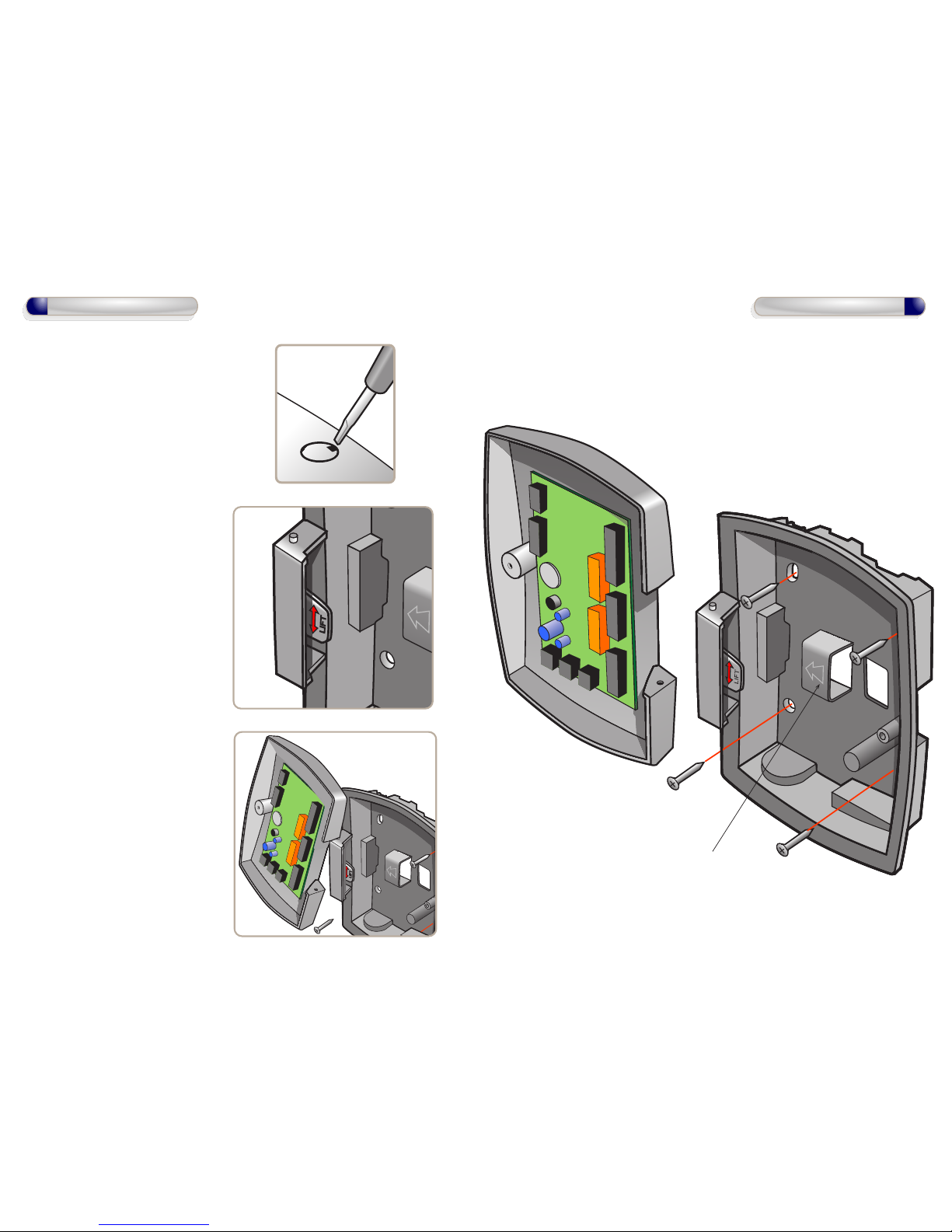
1. To open front cover of GSD Controller,
remove screw cap using screwdriver
then loosen screw.
2. Remove door from unit
(see inset) before screwing
the rear enclosure to the wall.
To remove front cover lift tab up
and unhook door.
To re-attach front cover: hook door
over top pip and rotate into
position and push tab down
to secure.
4
Installation Diagrams
4. Re-attach the front cover
5
Installation Diagrams
3. screw the rear enclosure to the wall.
as shown below.
Use for retaining cables.
Page 4
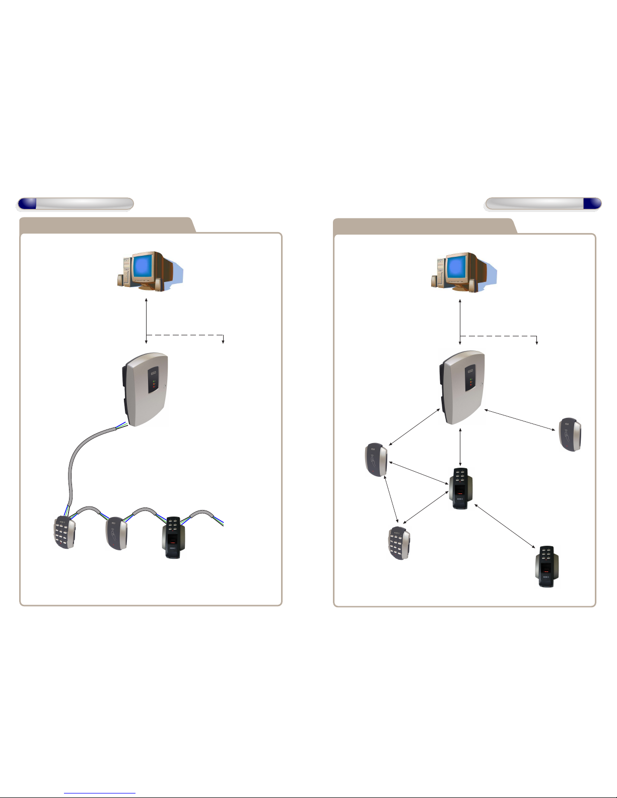
RS485 Connection to Door Controls
6
System Overview
Door Control
#1
Door Control
#2
Door Control
#3
Door Control
#4 - 10
RS485 Network to Door Controls
Max Cable Length 1.4 km.
Daisy Chain Configuration Only.
RS485 Network to Controllers
Max number of Controllers 3
Max Cable Length 1.4 km
Controller
#1
Controller
#2 - 3
Note: If using a single Controller,
an RS232 cable may be used.
Max cable length 10 meters
Wireless Connection to Door Controls
Door Control
#1
Door Control
#2
Door Control
#3
Door Control
#5 - 10
RS485 Network to Controllers
Max number of Controllers 3
Max Cable Length 1.4 km
Controller
#1
Controller
#2 - 3
Door Control
#4
Note: Door Controls can be installed within 50 meters
of the Controller or within 50 meters of any other Door Control
as each Door Control will function as a repeater. Each repeater
transmits data to/from the Controller.
50 meters
7
System Overview
50 meters
50 meters
50 meters
50 meters
50 meters
50 meters
Note: If using a single Controller,
an RS232 cable may be used.
Max cable length 10 meters
Place a 120ohm
Termination Resistor
across A & B on the last
Door Control in the chain.
Place a 120ohm
Termination Resistor
across A & B on the
Controller
Page 5
Fire Alarm
Panel
12V Linear
Power supply
A
B
0V
Note : Used ONLY for
Wired 485 Network
Connections.
Door Network
A
B
COM
TX
RX
PC Netwrok
PC Direct
Sounder
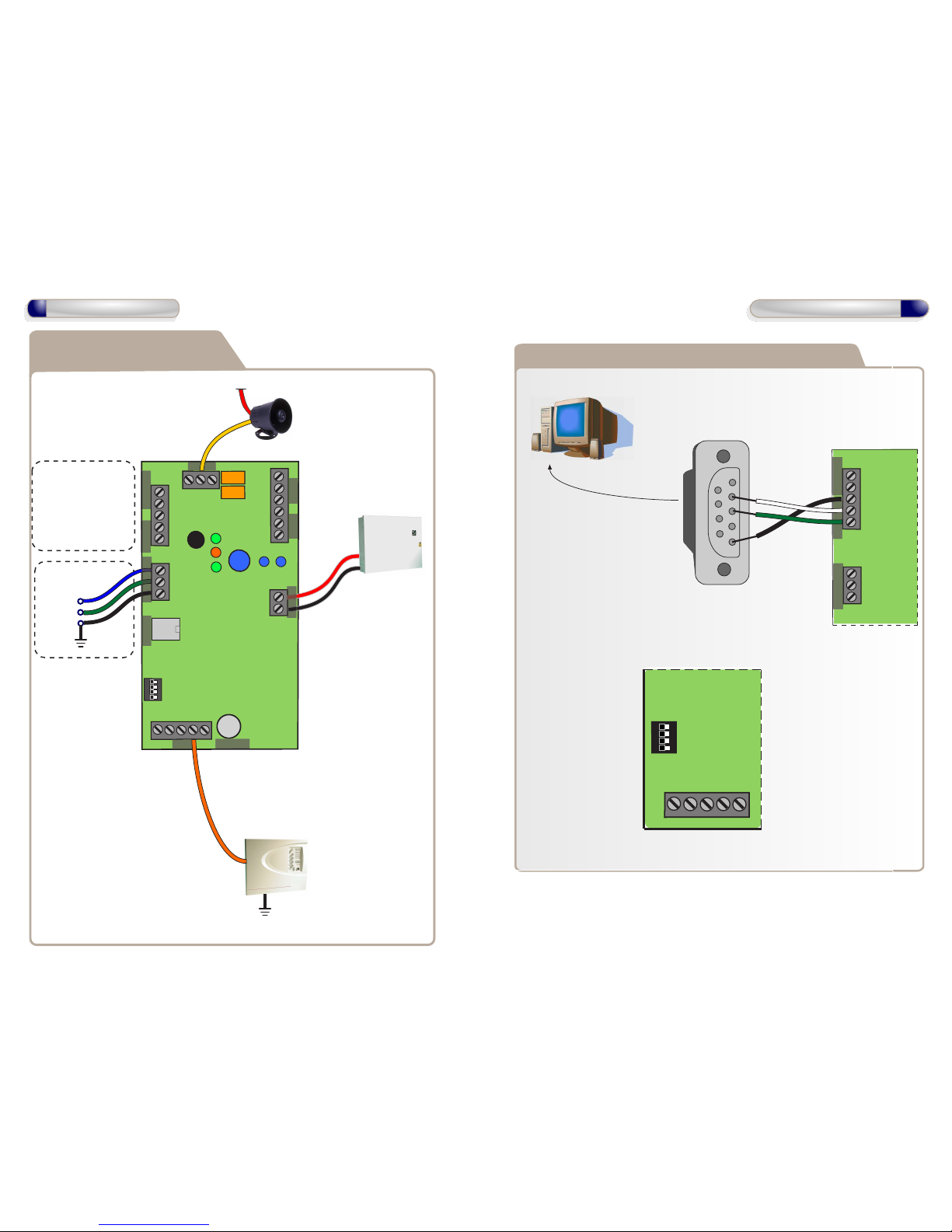
PC Network Connections
can be used for multiple
controllers See page
10 for wiring
Use PC Direct
Connections if using
a single controller
See page 9 for wiring
Wiring Diagrams with
Local Door Connections
NC
COM
NO
NC
COM
NO
Relay 2
NOTE:
Common OV from the
Fire Alarm Panel and the OV
from the Controller to
avoid any ground loop issues.
When the fire alarm
is activated ( ie 0V
removed from IP3)
the local door will be
opened.
8
Wiring Diagrams
IP4
IP3
0V
IP2
IP1
+V
0V
VOUT
OP3
OP4
A
B
COM
1 2 3 4
OFF
ON
IP4
IP3
0V
Inputs
TCP_IP
3V Lithium
Power In
12V
Outputs
Relay 1
0V
9
Network Diagrams for Single Controller
A
B
0V
TX
RX
A
B
0V
Door Network
PC Netwrok
Connect DB9 cable
to serial port on PC
Maximum cable
length 10 meters
Direct Connect - All Dip Switches OFF
PC Direct
DB9 Female
Serial Cable
PC Direct Connection can be used, when
using ONLY one GSD Controller.
Set the Direct address to
ALL dip switches OFF
(see below )
Network Diagrams
OFF
ON
1 2 3 4
IP4
IP3
0V
IP2
IP1
1
5
2
3
4
9
8
7
6
Page 6
10
Network Diagrams
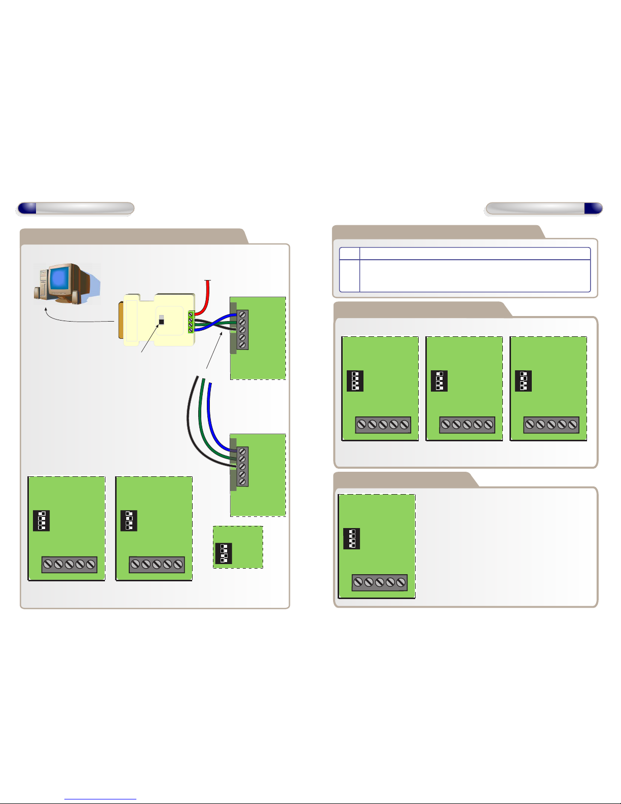
Network Diagrams for Multiple Controllers
19200
9600
12V - 1
0V - 2
B - 3
A - 4
A
B
0V
TX
RX
PC Direct
12V
PC Netwrok
Connect using RS232-RS485
cable to serial port on PC
PC Network Connections, when using more
than one GSD Controller.
Daisy chain the PC network A , B , 0V to each controller.
Set an individual address for each controller
between 1 & 3 using the dip switches
(see below )
RS485 Converter
A
B
0V
TX
RX
PC Direct
Controller 1
Controller 2
PC Netwrok
Address 1 - Set SW1 ON Address 2 - Set SW2 ON Address 3 - Set SW3 ON
Controller 1 Controller 2
Set Baud Rate to 19200
Daisy Chain
each controller
A
B
0V
1 2 3 4
Controller 3
OFF
ON
1 2 3 4
IP4
IP3
0V
IP2
IP1
OFF
ON
1 2 3 4
IP4
IP3
0V
IP2
IP1
OFF
ON
Setting the GSD Controller address
Direct Connect - All OFF Address 1 - Set SW1 ON Address 2 - Set SW2 ON
Note: Address 3 - Set SW3 ON only
The Controller Address is set by configuring the Dip swithces as shown below.
Configuring GSD Controller Communications
Step Description
1. Click ‘Settings’ tab to open communications window. Select the Serial Port
Number connected to the Controller.
OFF
ON
1 2 3 4
IP4
IP3
0V
IP2
IP1
OFF
ON
1 2 3 4
IP4
IP3
0V
IP2
IP1
OFF
ON
1 2 3 4
IP4
IP3
0V
IP2
IP1
11
Network Diagrams
Restoring Factory Settings
Example: All Dip Swithces are set to the ON position.
To restore the factory default setting , Set ALL Dip
Swithces 1,2,3 & 4 to the ON position and then
power-up the GSD Controller.
OFF
ON
1 2 3 4
IP4
IP3
0V
IP2
IP1
Note: Factory Default settings will be restored after
powering up the controller with All dip-swithces ON. The
dip-switchess should then be set to the controller
address as shown above in section “Setting the GSD
controller address”
Page 7

12
Operation Instructions
Phase 1 - Setting up the GSD Controller
Step Description
1. Install the main GSD Controller and power up
2. Default the controller immediately via the dip switch settings
(see instructions on page 11
3. Important! Once powered up and the controller has completed the default
the process – reset the dip switches to the correct address positions.
(see instructions on page 11)
4. Connect the PC lead to the Contoller and configure the PC Comms.
A. If using a Serial to USB converter –Follow USB converter instructions.
B. Establish the Com Port no.
5. Follow instructions on the CD provided to install the GSD PC application.
To download the latest drivers, enter the following link in your web browser
http://www.globalsecurity.ie/download/GSDWin Access en-US.zip
6. Open the application with the PC connected to the controller
A. Log in to the application as the Engineer (not the administrator) with
the password 6666.
B. Go to the settings tab and set the Com port number for the
Controller as established above.
C. The Controller icon will change colour to show that the Controller is
on-line.
13
Operation Instructions
Phase 2 - Configuring the GSD Controller
Step Description
1. Open the ‘Doors’ tab in the main menu to add the required number of new
doors to be part of this network. 1 door will already be added by default.
Click on the “+” button to add new doors. “-” to remove doors.
2. Make sure all doors are ‘Enabled’ and then click Save.
3. Open the Settings Tab and do a Full Download to the Controller – this
gives the Controller a clean set of instructions before beginning to enrol
doors onto the network. This will take approximately 1 minute.
4. WARNING! A New Network should only be created on first installation.
Creating a new network will overwrite any existing network information
and any enrolled Door Controls will be un-enrolled. All Door Controls will
have to be defaulted and re-enrolled on the new network that has just
been created!
A new network is now ready to be created.
Go to the ‘Controllers’ tab and Click on the ‘Create a New Network’ button.
Click Yes on the ‘Hit yes if you want to proceed’ pop-up.
Note: The red LED on the Controller PCB will remain ON during the
process. It will take about 20 - 60 seconds to complete. The red LED will
start to flash again when the Network is created.
Page 8

15
Operation Instructions
Phase 3 - Enrolling Door Controls
Note: For Wired 485 Door Controls, right click on the Controller on the
right hand side of the application and select ‘Manually Assign Address’
from the drop down menu.
Once all new Door Controls are found by the Controller they will all
‘beep’ with the number of the next available address/door position on the
Controller.
e.g. if door 2 is the next available address then all Door Controls will beep
at the same time with 2 beeps. This is basically saying that any door can
be assigned to this address – it’s up to the installer to decide which one.
Also – you will notice that the Key back light of the keypad Door Controls
will be illuminated with the next available address as well.
i.e. Key 2 will be illuminated for this example.
3. Go to the Door control that you want to make door 2 on the network
system (it should be beeping 2 times). Press any key on this keypad and
the system will automatically assign this door control to door 2 location on
the system. Present a card if the Door Control is Prox Only.
Note: All other Door Controls will now start beeping with the next
available address i.e. ‘3 beeps’ in this instance and so on every time you
enrol a new Door Control. The Key back light will also correspond to
each address as the system fills up.
Step Description
2. The controller is now ready to allow Door Controls to enrol onto the
Network – click the ‘Allow Doors to join this Controllers Network’ on
the ‘Controllers’ tab to start the controller scanning for new doors that do
not already have an address – only DoorControls without an address can
enrol – this will avoid other networks and Door Controls in the same
building on a different network becoming part of this new network!
14
Operation Instructions
Phase 3 - Enrolling Door Controls
Step Description
All Door Controls should be installed at this point and powered up.
1. All Door Controls must be defaulted before joining a network.
Note: Door Controls will be shipped with their factory default settings.
Enter Engineer mode on each Keypad Door Control in the following way
A. Press X followed by 6666
B. Enter 55 –to default
C. Press the tick to confirm – the keypad will now go through the
process of defaulting itself.
D. When this process has complete hit the X button to leave engineer
mode and to put the keypad control in the ‘Scan Mode’ – the Red Led
on the Door Control will now be in flicker mode as an indication.
E. Repeat the process for all keypad Door Controls
Enter Engineer mode on each Wi-Bio Door Control in the following way
A. Enter 6666
B. Enter 55 –to default
C. Scan Finger to confirm – the Door Control will now go through the
process of defaulting itself.
D. When this process has complete Scan Finger again to leave engineer
mode and to put the Door Control in the ‘Scan Mode’ – the Red Led
on the Door Control will now be in flicker mode as an indication.
E. Repeat the process for all Wi-Bio Door Controls
Enter Engineer mode on each Prox Only Door Control in the following way
A. Add a programming card to the Door Control by presenting a card
twice on power-up. The security wing must be removed first!
B. Present this new programming card to enter Engineer mode.
C. Present the programming card again to select “Default mode”.
D. Present any other card once to default the Door Control.
E. When this process has complete the Door Control will be in the ‘Scan
Mode’ – the Red Led on the Door Control will now be in flicker mode
as an indication.
Page 9

16
Operation Instructions
Phase 3 - Enrolling Door Controls
Step Description
4. Once all Door Controls are enrolled onto the network – go back to the
Controller application and click the ‘Secure Network’ button
– this safeguards the systems – if you select another tab on the aplication
this will happen automatically.
5. Select each Door on the application and configure individual settings such
as Timed Actions, Relay Times, Ajar Times, Door Option and Alarm Options
etc.
IMPORTANT: A timezone must be selcted in ‘Timed Actions’ for one of the
options: Card and PIN, Any Card, Card or PIN , or PIN only.
If all of these are set to ‘inactive’ then access will be denied for all cards
and PINs on that Door Control.
Example: Disabling cards/fobs, Enabling PIN codes only on a Wi-PIN&Prox
Set the Timed Action “Card or PIN” to “Inactive” and setting the Timed
Action “PIN Only” to “All day,Every Day”. This will grant access for PIN
codes and deny access for cards and fobs.
To enable or disable Timed Actions at specific times, select a timezone
from the drop-down list instead of “All Day, Every day”.
Phase 4 - Configuring Users
Step Description
1. Enable a User by ticking the ‘Enabled’ box for each User
2. Assign a Name to the User
3. Assign a UserGroup from the drop-down menu. The Usergroup will
determine the access levels for this User. Refer to section below on
‘Configuring Access Levels’ for information on User Groups.
4. Assign a Card , PIN number and enrol FingerPrints for the User. Refer to
section FingerPrint Enrolment on page 19
Click ‘save’ to transmit these changes to the Controller.
17
Operation Instructions
Page 10

18
Operation Instructions
Phase 6 - Downloading Configuration
Phase 5 - Configuring Access Levels
Step Description
Access Levels are controlled by creating UserGroups and assigning the
UserGroup to a User as decribed in section ‘Configuring Users’.
1. UserGroups are created by combining pairs of DoorGroups with
Timezones. Each UserGroup can have up to 6 pairs of DoorGroups and
Timezones. Select DoorGroups and Timezones from the drop-down menus
to add to the current UserGroup.
2. Timezones are the periods of time for each day of the week that access
will be granted. Select times and tick the days of the week this time is valid.
4 time periods can be created for each timezone. Select ‘Holiday Access’
to grant access for holiday periods. Double click on the ‘Holiday Access’ to
add days to the holiday periods. Use the calender to select these days.
3. DoorGroups are created by grouping doors together. e.g all the entry and
exit doors could be grouped together as ‘Peremiter Doors’. Select a Door
from the ‘All availble Doors’ window and drag it to the ‘Doors in Current
Door Group’ to add it to the Door Group. Repeat for adding each door.
Step Description
After all users, access levels and door control settings have been finalised,
a full download to the controller should be carried out.
1. Go to the ‘Settings’ tab and click on ‘Download Configuration’. A pop-up
window will appear, tracking the status of the download. All settings will be
downloaded to the Controller and Door Controls.
19
Operation Instructions
Enrolling User FingerPrints
Step Description
Note: Make sure the USB Fingerprint reader is attached to the PC
1. Select the User for fingerprint enrollment
2. Click on the ‘Fingerprints’ button.
3. Click on ‘Enrol’ tick box and place finger on the enrolment reader. An
image of the fingerprint will appear on the screen. Ensure that the image
quality is good and a value of at least 90% is achieved. Refer to section
‘Finger Placement’ for correct finger placement and example of good
quality image. Repeat this process if this is not achieved on first attempt.
4. Click ‘Save’ using a good quality template only. Poor Quality templates can
lead to false rejections later when trying to gain access .
Page 11
Correct Finger Placement
20
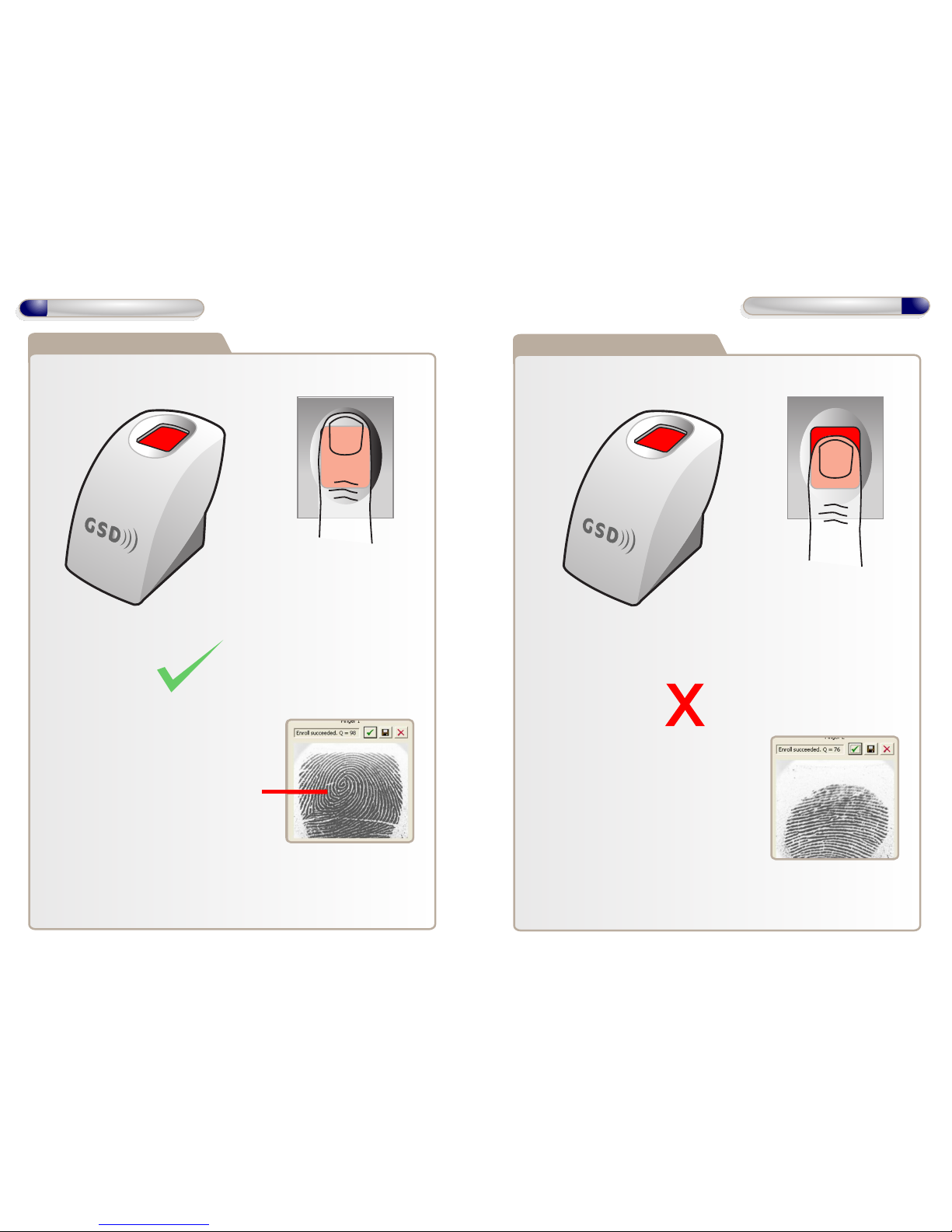
Finger Placement Wi-BIO
Note: Good Quality image, Fingerprint core
is center of sensor window
Note: Ensure that the core of finger is
centered on the sensor window during
the enrollment process. This will increase
the quality of the fingerprint template
Good Quality Image
Note: The System does not store the finger
print. It uses an algorithm to generate a
binary representation using sample points
from the fingerprint. It uses this information
to then validate each users fingerprint.
Incorrect Finger Placement
21
Finger Placement Wi-BIO
Poor Quality Image
Note: Poor Quality image, No Fingerprint
core on sensor window.
This can result in poor template quality that
can lead to false rejection issues later when
the user is trying to gain access.
Note: Incorrect placement : finger does not
fully cover the sensor window.
Page 12
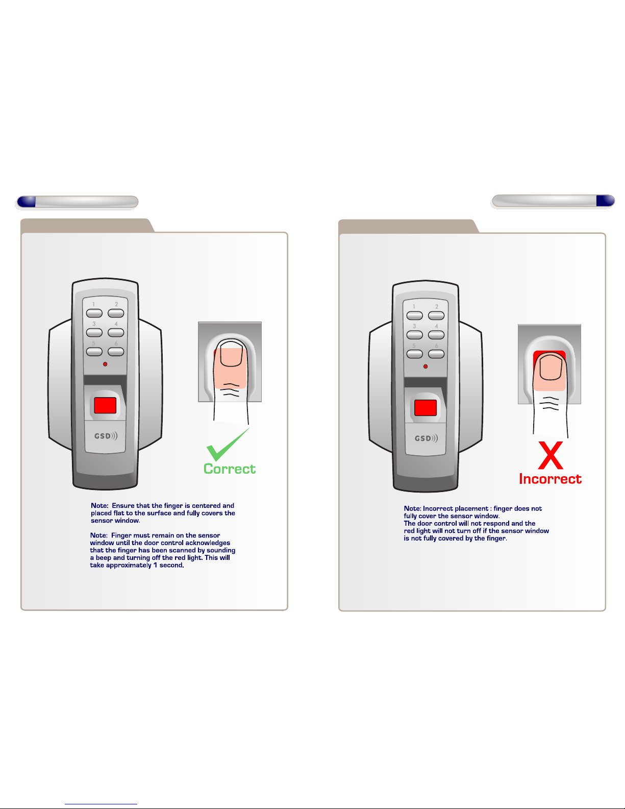
Correct Finger Placement
22
Finger Placement Wi-BIO
Incorrect Finger Placement
23
Finger Placement Wi-BIO
 Loading...