

GSD Wi-Plus Installation Instructions Manual
3
Contents
6
Installation Diagrams
9
8
System Overview
Wi-Plus Controller
Other products from GSD
For more information on the Wireless Network System visit our website
www.globalsecurity.ie
4
Installation Instructions
12
Network Diagrams
Wiring Diagrams
19
Fingerprint Enrollment
Operating Instructions
YOUR SECURITY IS OUR PRIORITY
Installation Manual V2.08
Global Security Devices Ltd: No.3 Broomhill Business Complex, Tallaght,
Dublin 24, Ireland, Phone: +353 (1) 524 2691, Email: info@globalsecurity.ie
www.globalsecurity.ie
2
3
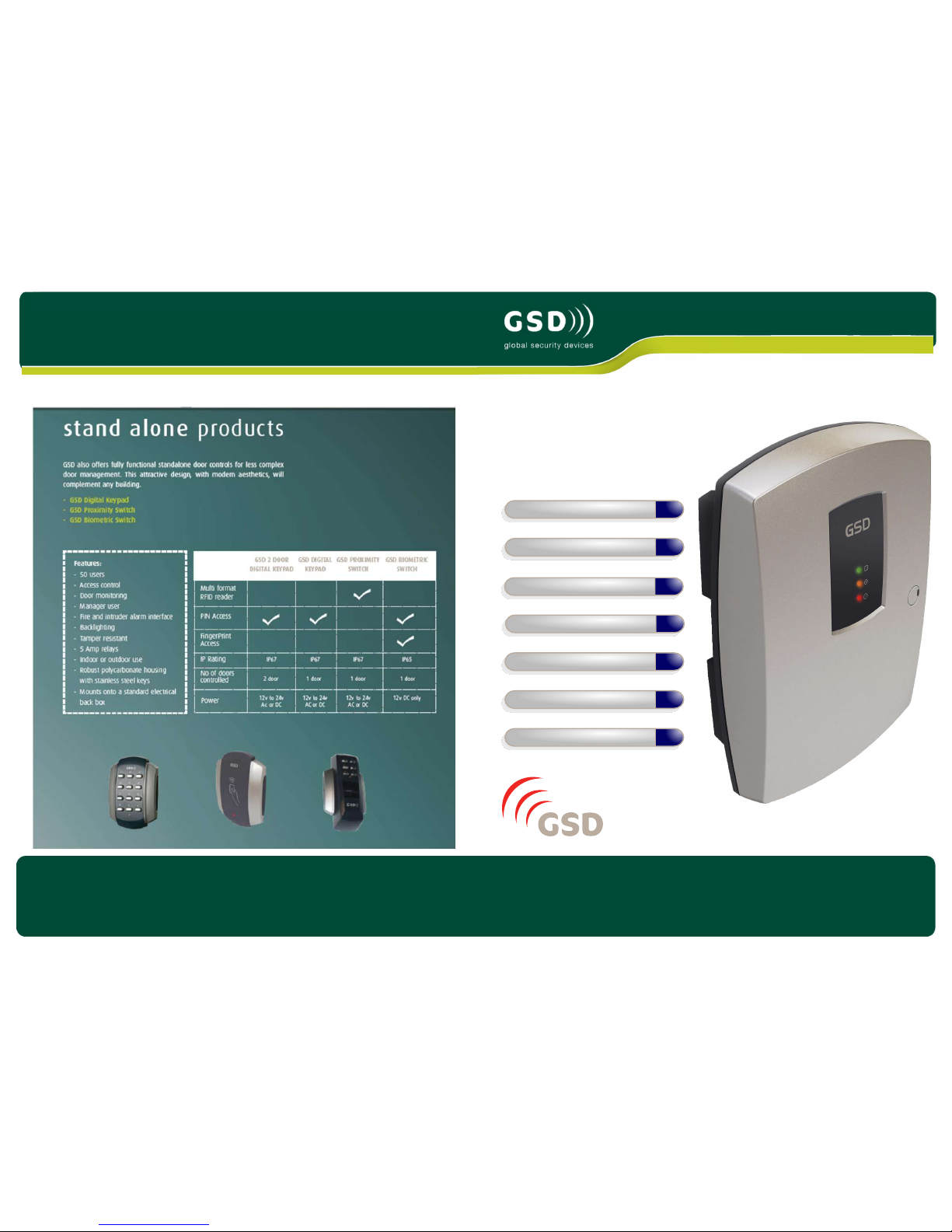
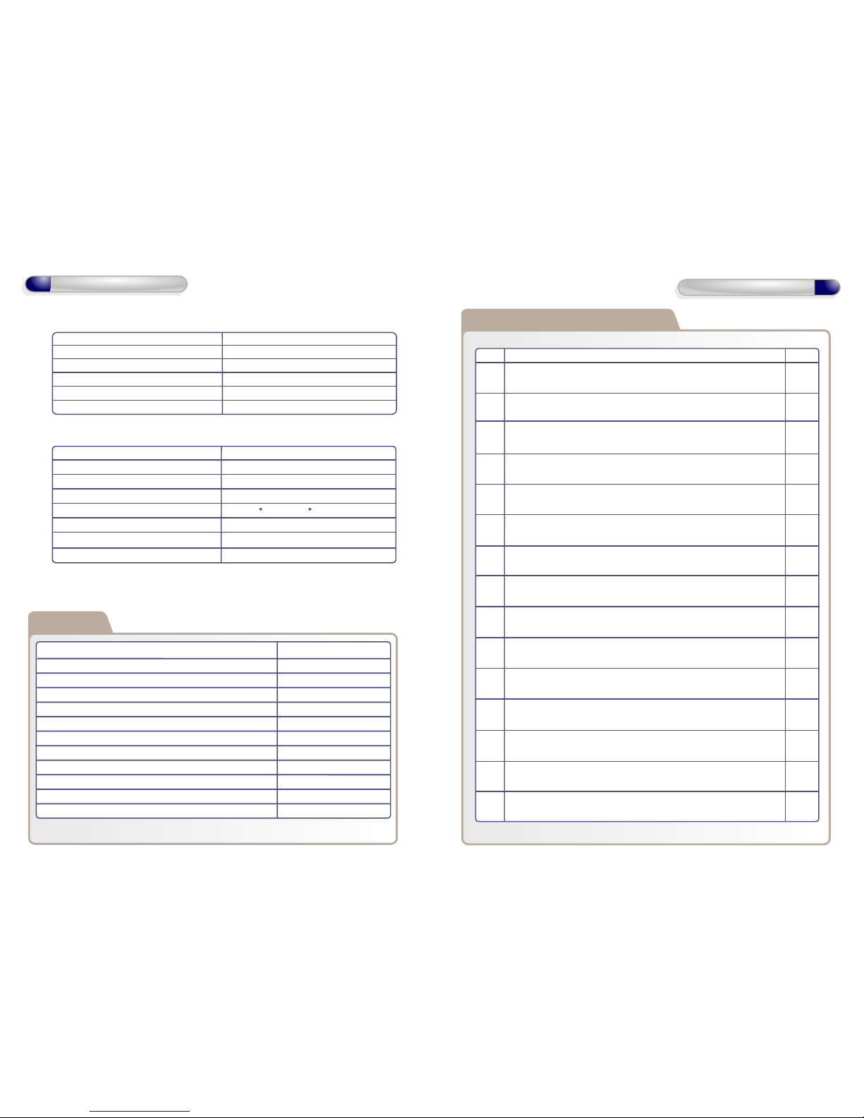
Technical Specification
Power Supply 12 DC
Current consumption 120mA
Current consumption with load (max) 160mA
Relay Contact Rating 5 Amps /240V ac
Moisture Resistance Indoor Use Only
Dimensions W. 135mm D. 46mm H. 200mm
Technical Specs - GSD Wi-Plus Controller
Power Supply 12 DC
Current consumption 110mA
Current consumption with load (max) 145mA
Relay Contact Rating 5 Amps /240V ac
Operating Temperature - 20 C to +60 C
Moisture Resistance IP 67 ( IP65 on Wi-Bio )
Dimensions - Flush Mount W. 87mm D. 21mm H. 119mm
- Surface Mount W. 87mm D. 35mm H. 119mm
Technical Specs - Wi-Plus Door Controls
Features
Doors controlled
Users
User Groups
Time Zones
Door Groups
Reporting Facility
Challenge Facility
Logging
Input/Output Mapping
Supports Wireless & RS485 Networks
Automatic Backup Facility
Database Encryption
10
5000
16
16
16
Yes
Yes
Unlimited
CCTV & Lift control
Yes
Yes
Yes
Installation Steps
Step Description Page
1 Install the Controller using the Installation Diagrams 4-5
2 System Overview 6-7
3 Wire the Controller using the Wiring Diagrams 8
4 Install and wire each Door Control. Refer to the Door Control
Manual for instructions.
5 Connect the Controller to the PC using Network Diagrams 9-11
6 Restoring Factory Defaults 11
7 Phase 1- Setting up the GSD Controller via the PC application 12
8 Phase 2 - Configuring the GSD Controller via the PC application 13
9 Phase 3 - Defaulting Door Controls 14
10 Phase 4 - Enrolling Door Controls 15-16
11 Phase 5 - Configuring Users 17
12 Phase 6 - Configuring Access Levels 18
13 Phase 7 - Downloading Configuration 18
14 Enrolling User Fingerprints 19
15 Correct Finger Placement techniques 20-23
Installation Steps
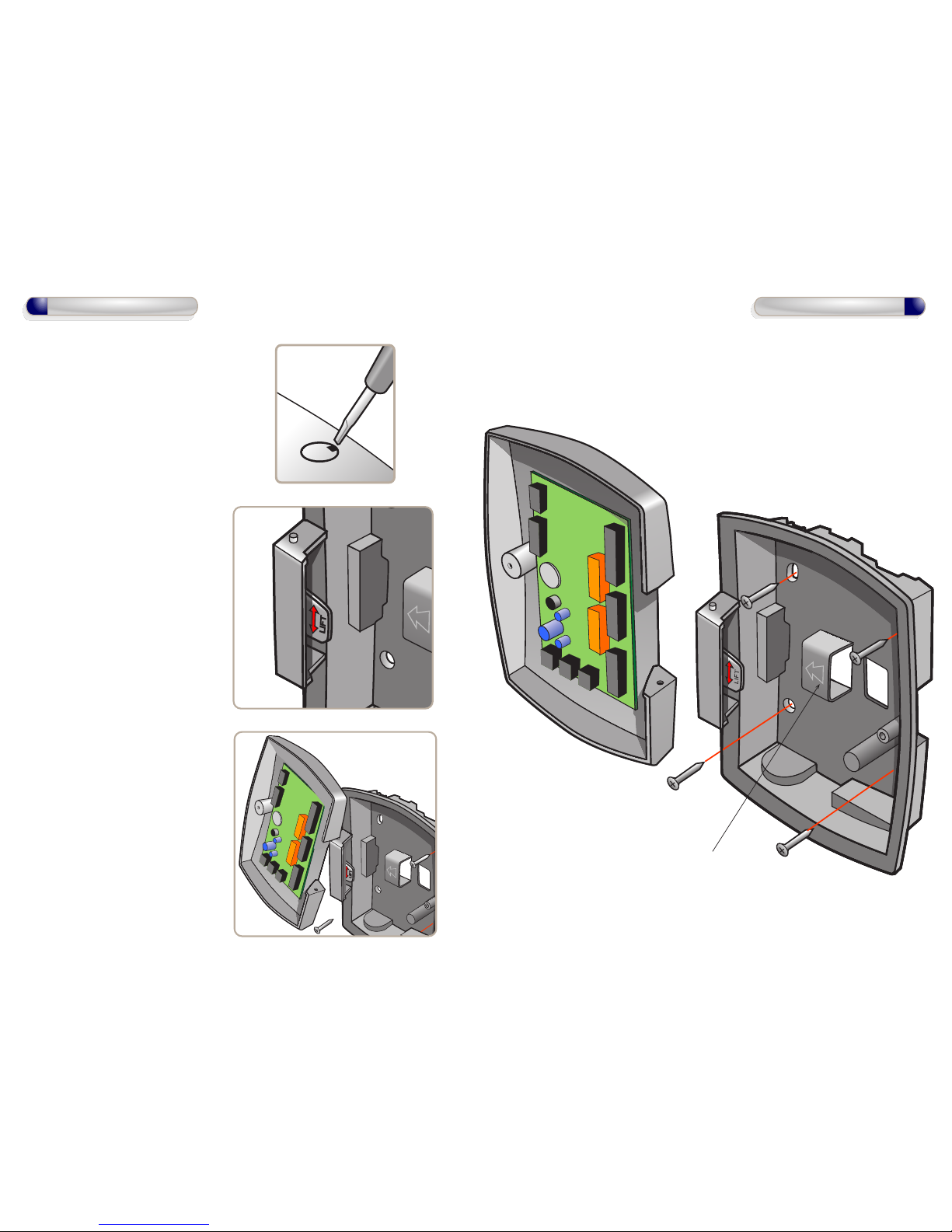
1. To open front cover of GSD Controller,
remove screw cap using screwdriver
then loosen screw.
2. Remove door from unit
(see inset) before screwing
the rear enclosure to the wall.
To remove front cover lift tab up
and unhook door.
To re-attach front cover: hook door
over top pip and rotate into
position and push tab down
to secure.
4
Installation Diagrams
4. Re-attach the front cover
5
Installation Diagrams
3. screw the rear enclosure to the wall.
as shown below.
Use for retaining cables.
RS485 Connection to Door Controls
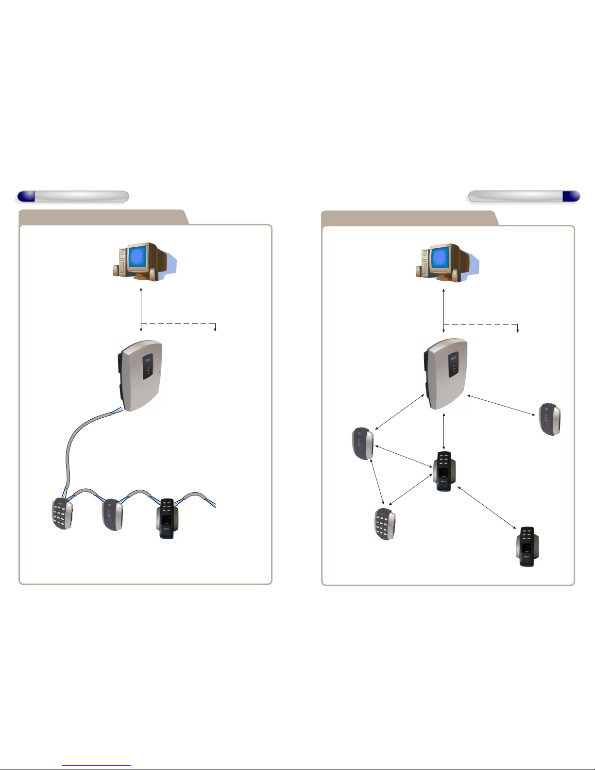
6
System Overview
Door Control
#1
Door Control
#2
Door Control
#3
Door Control
#4 - 10
RS485 Network to Door Controls
Max Cable Length 1.4 km.
Daisy Chain Configuration Only.
RS485 Network to Controllers
Max number of Controllers 3
Max Cable Length 1.4 km
Controller
#1
Controller
#2 - 3
Note: If using a single Controller,
an RS232 cable may be used.
Max cable length 10 meters
Wireless Connection to Door Controls
Door Control
#1
Door Control
#2
Door Control
#3
Door Control
#5 - 10
RS485 Network to Controllers
Max number of Controllers 3
Max Cable Length 1.4 km
Controller
#1
Controller
#2 - 3
Door Control
#4
7
System Overview
Note: If using a single Controller,
an RS232 cable may be used.
Max cable length 10 meters
Place a 120ohm
Termination Resistor
across A & B on the last
Door Control in the chain.
Place a 120ohm
Termination Resistor
across A & B on the
Controller
Note: Door Controls can be installed within 30 meters
of the Controller or within 30 meters of any other Door Control
as each Door Control will function as a repeater. Each Door Control
transmits data to/from the Controller. These distances are a guideline.
The actual communication range depends on building shape and
construction methods used.
 Loading...