

Page 1
Technical Specification
Trouble shooting
Installation Instructions
2
Operation Instructions
25
Contents
29
8
Installation Manual V1.00
Global Security Devices Ltd: No.3 Broomhill Business Complex, Tallaght,
www.globalsecurity.ie
YOUR SECURITY IS OUR PRIORITY
i 7/70
Grade 2 Hybrid Intruder Alarm System
Page 2

Installation steps
Step
1.
2.
3.
4.
5.
6.
7.
8.
9.
10.
11.
12.
13.
14.
15.
16.
17.
18.
19.
20.
21.
22.
Description
Network Overview
Install the controller
Restore factory defaults
First power-up default settings
Start the installer menu
Define areas (optional)
Install devices
Configure zones
Configure keypads (optional)
Configure sirens (optional)
Configure users
Configure areas
Configure timers
Walk testing
Output testing
Soak testing (optional)
Trouble shooting
Set up reporting (optional)
Technical Specifications
Menus / Wizards
Page
3.
4.
10.
11.
12.
15.
16.
18.
19.
20.
20.
21.
22.
23.
24.
24.
25.
27.
29.
32.
4-digit codes
5-digit codes
6-digit codes
6666
1111
06666
01111
006666
001111
Default installer code
Default user 1 code
Default installer code
Default user 1 code
Default installer code
Default user 1 code
2
Installation Instructions
39
Operation Instructions
Page 3
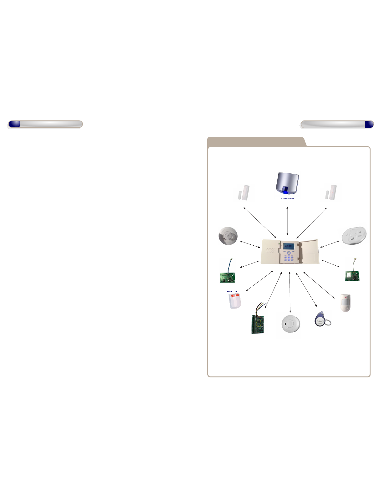
System Overview - Network Plan
GSD i7/70 Panel
PIR
Shock/Contact
Smoke
Detector
5 Zone
Expander
WiFi IP
Communicator
Wired IP
Communicator
Contact/Universal
Fob
Carbon Monoxide
Detector
Heat
Detector
Panic
Alarm
External
Siren
3
Installation Diagrams
38
Operation Instructions
Page 4
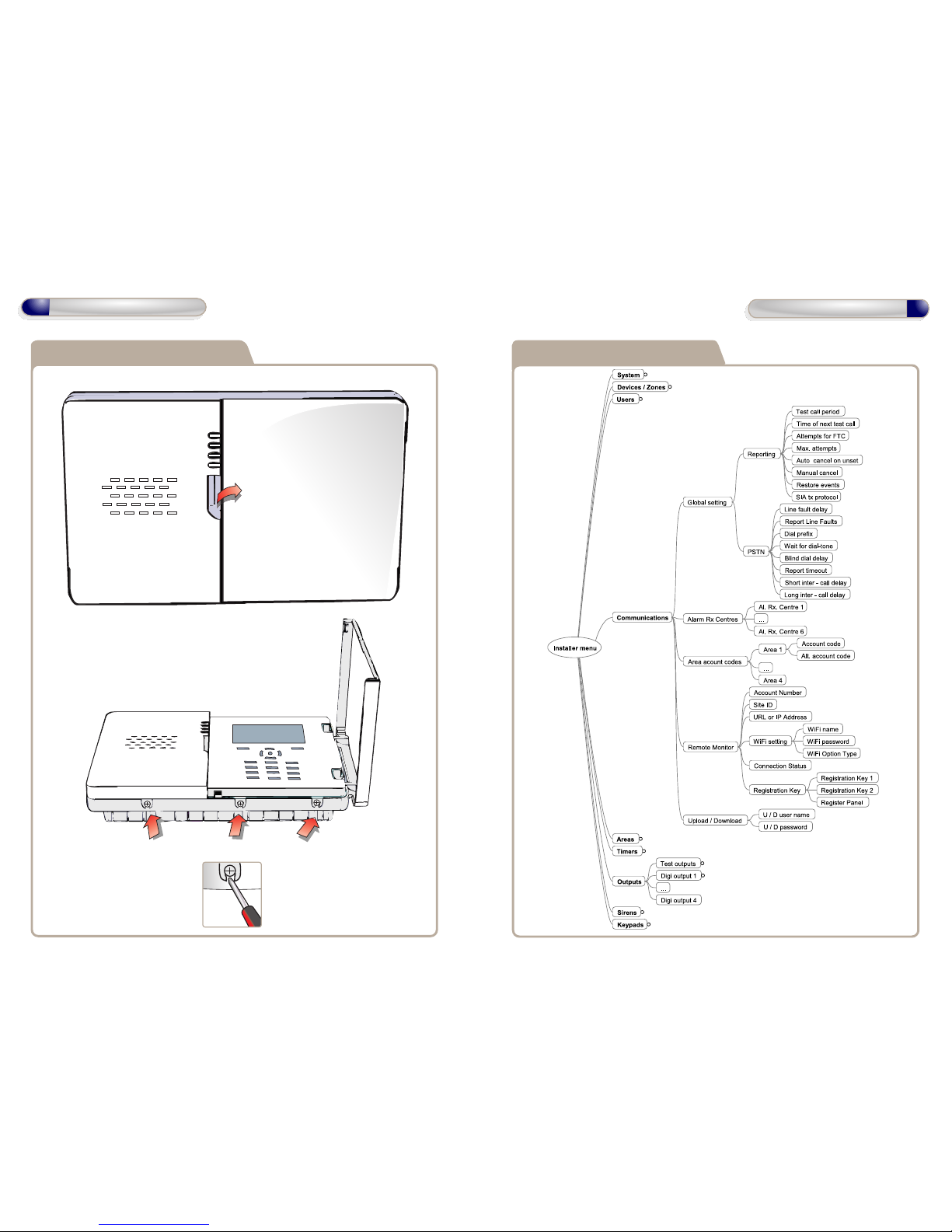
PA mounting
1: to open, lift cover
upwards
2: loosen
retaining screws
to release
covers
Control Panel Opening Communications & Outputs
4
Installation Diagrams
37
Operation Instructions
Page 5

3: lift Cover 1
upwards to
remove before
removing Cover 2
4: lift cover 2
upwards to
remove
Cover 1
Cover 2
pull clip forward
to remove battery
Control Panel opening
Battery Removal
Users, Sirens & Keypads
Z1
GND
Z2
GND
Z3
GND
Z4
GND
Z5
GND
OP1
OP2
GND
V+
5
Installation Diagrams
36
Operation Instructions
Page 6
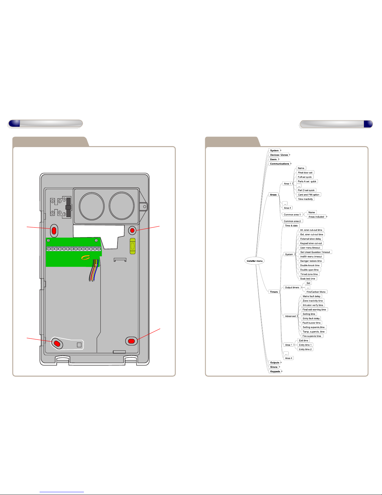
mount hole
mount hole
mount hole
mount hole
Control Panel Mounting
Remove covers 1 & 2 and battery before mounting
See instructions for Control Panel Opening and
Battery Removal.
Timers & Areas
Z1
GND
Z2
GND
Z3
GND
Z4
GND
Z5
GND
OP1
OP2
GND
V+
6
Installation Diagrams
35
Operation Instructions
Page 7

Control Panel Wiring
Z71
GND
Z72
GND
ABAUX+
AuX -
Bell +
Bell -
Strobe +
Strobe -
Tam Rtn
BHO
Phone A
Phone B
Line A
Line B
Fuse Rating : 230VAC 315mA
Main
Input
Cable
230VAC
Neutral
Live
Earth
Warning : Installation should only be carried out
by a suitably qualified person.
Remove cover 1 to access the wiring terminals.
See instructions for Control Panel Opening.
Devices / Zones
IP Card
Socket
IMON
7
Installation Diagrams
34
Operation Instructions
Page 8
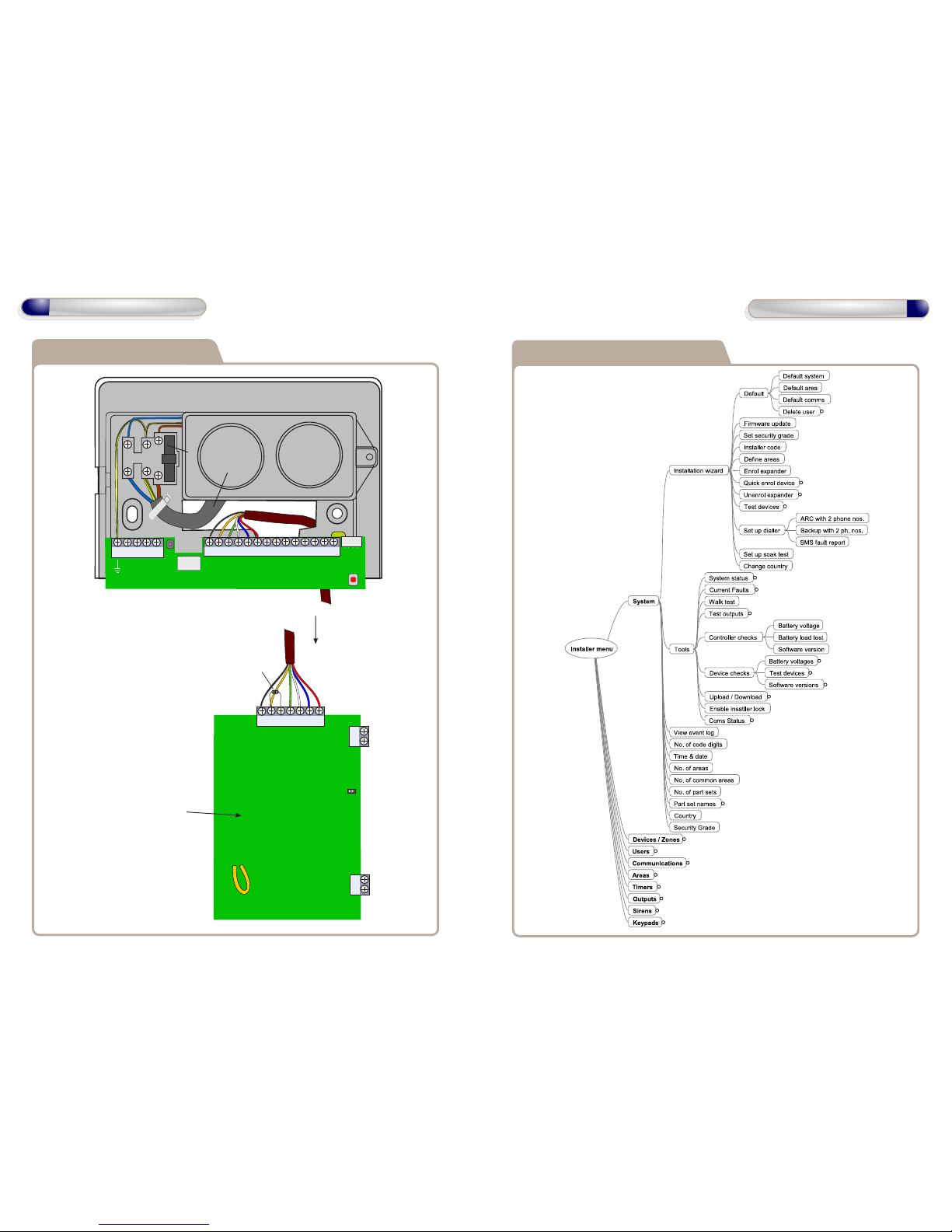
Wiring External-Siren
Bell +
Bell -
Strobe +
Strobe -
Tam Rtn
BHO
Phone A
Phone B
Line A
Line B
Bell +
Bell -
Strobe +
Strobe -
Tam Opt
Tam Rtn
BHO
to External
Siren
External
Siren
PCB
Tamper
Resistor
4K7
Batt +
Batt -
Sounder +
Sounder -
Extenal Tamper
Loop
HeartBeat
LED
Supports third party
Wired External Sirens
Installation Wizards & Tools
Z71
GND
Z72
GND
ABAUX+
AuX -
Bell +
Bell -
Strobe +
Strobe -
Tam Rtn
BHO
Phone A
Phone B
Line A
Line B
Fuse Rating : 230VAC 315mA
Main
Input
Cable
230VAC
Neutral
Live
Earth
IMON
IP Card
Socket
33
Operation Instructions
8
Operation Instructions
Page 9
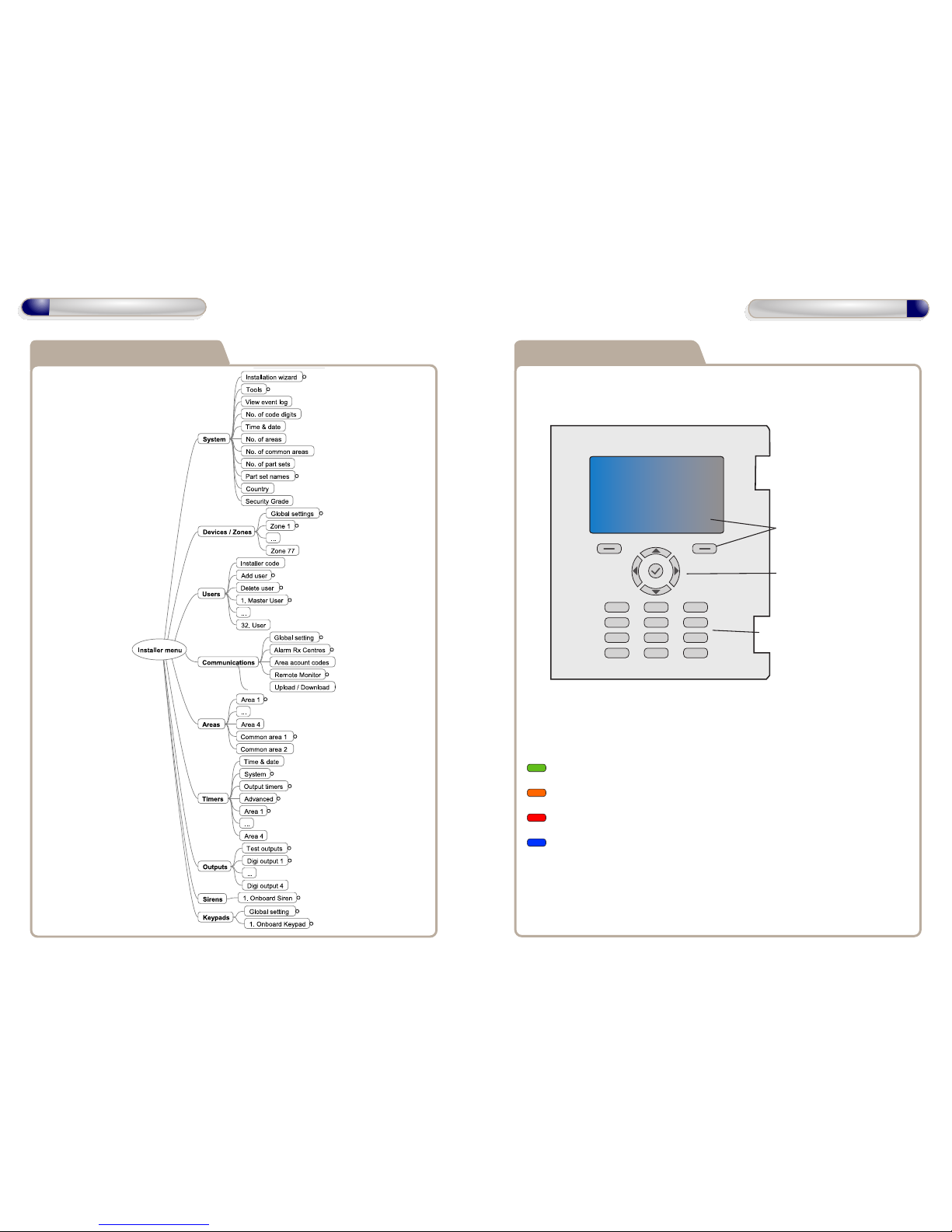
keypad features
3 DEF2 ABC1
6 MNO5 JKL4 GHI
9 DEF8 DEF7 PQRS
#0
*
soft keys relating to on
screen menu information
navigation and ok keys
alpha numeric keypad
LED Status:
Green LED: Solid = Battery fully charged, Flashing = Battery charging
Amber LED: Fault Indication
Red LED: Alarm Indication
Blue LED: Solid = Full Set, Flashing = Part Set or some Areas Set
Installer menu Overview
32
9
Operation InstructionsOperation Instructions
Page 10
ACE Type
Non-volatile memory
Settings required to comply
with EN50131.
Note: compliance labelling
should be removed or adjusted
if non-compliant configurations
are selected.
Additional functions
GSD i70
N/A
Static RAM with memory support battery: CR2032.
Battery life 5 years.
All grades
Alarm event log limit: 3 - 10
Int siren cut-out time: 90s - 15 min.
Ext siren cut-out time: 90s - 15 min.
Ext siren delay time:
10 min.
Mains fault delay:
60 min.
Entry fault delay:
30 s
Entry time 1:
45 s
Entry time 2:
45 s
Grade 1
No. PIN digits: 4 - 6
Code tamper attempts:
10
Code tamper repeat attempts:
10
Setting Supervision time:
60 min.
Reporting test call period:
24 hours
Grade 2
No. PIN digits: 5 - 6
Code tamper attempts:
10
Code tamper repeat attempts:
10
Tamper Supervision time:
120 min.
Setting Supervision time:
20 min.
Reporting test call period:
24 hours
Fire alarm processing, medical alarm processing, inactivity
alarm processing. All of these are reset by user access
level 2.
1.
2.
3.
4.
5.
6.
Restoring All Factory Default Settings
IMPORTANT NOTICE
This should only be carried out when you want to completely default the
control panel back to its original default state as ALL programming of
the system will be lost!
Remove the multi colored harnessfrom the i7/70 panel.
Disconnect the battery pack from the i7/70 panel PCB by unplugging the
battery from the battery terminal.
Remove the J2 link from the i7/70 panel PCB. See control panel opening
for removal of covers.
Wait 10 s then reconnect the mains PSU and the battery pack.
The i7/70 Panel will start up in the installer menu - this indicates the
configuration has been defaulted.
Replace the J2 link.
* After restoring factory default settings the following default codes exist
on the system.
4-digit codes
5-digit codes
6-digit codes
6666
1111
06666
01111
006666
001111
Default installer code
Default user 1 code
Default installer code
Default user 1 code
Default installer code
Default user 1 code
31
Technical Specification
10
Operation Instructions
Page 11
No. of devices
Indications made inaccessible
to level 1
Notification priority
Minimum PIN variations
Invalid PIN entries to cause
user interface to disable
Set conditions
Notification options
Automatic soak test end
No. of intrusion alarms for
automatic zone inhibit
GSD i70
1 controller/keypad/siren
0 - 4 sirens / external siren
1 - 71 sensors
By 30 s timeout
Fire Highest
Medical Alert
Personal Attack
Intrusion
Tamper
Faults Lowest
4 digits: 0000 is not allowed; 9999 variations
5 digits: 00000 is not allowed; 99999 variations
6 digits: 000000 is not allowed; 999999 variations
The number of digits is programmable in System - No. of
code digits.
10 by default. Programmable in Keypads - Global settings
Set state indicated by time limited message on keypads.
Opening of entry/exit door initiates an entry procedure.
Grade 1: options B and C
Grade 2: options B, C and D
End determined by programmable timer set in Timers System - Soak test time
5 by default. Programmable in Devices / Zones - Global
Settings - Swinger inhibit count
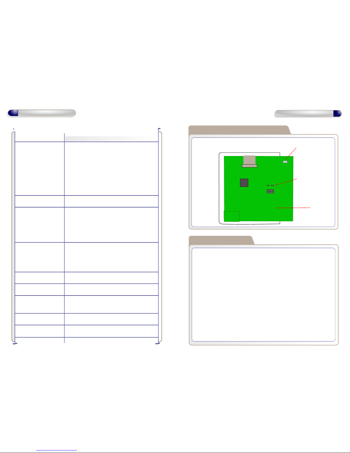
Restoring All Factory Default Settings
battery terminal
J2 link for
default settings
control panel PCB
See control panel opening for removal
of covers to access the control panel PCB.
The following settings are set after the control panel is restored to factory
default.
1.
2.
3.
1.
2.
First power-up settings
Country: Ireland
Security Grade: Grade 2
Number of PIN digits: 4
Settings the Time and Date:
Navigate to System - Time & Date: use up and down to select a field and
OK to change it. Enter a value using the number keys and press OK to store
the new value.
Press the Next soft key to finish.
11
Operation Instructions
30
Technical Specification
Page 12

1.
2.
3.
Start the installer menu
Start the installer menu: enter the installer code.
- The keypad will display any faults that have occurred on the system, including
faults that occurred but are not currently present.
- If no faults have occurred the keypad will immediately start the installer
menu.
Examine faults: navigate the faults menu (refer to Menu operation) to see
the faults indicated.
Continue to the installer menu: navigate to the top level of the faults menu
and press the Continue soft key.
- When you press the Continue soft key the keypad will reset the fault
indications of faults that are no longer present.
Operate the installer menu: described in Menu operation.
Technical specification
Name of manufacturer
Description of equipment
Standards
Security grade
Environmental class
Operating temperature
Relative humidity
Dimensions (w d h)
Weight (without batteries)
Type of interconnections
Methods of setting
Methods of unsetting
Fuse
Power supply description
Power supply input
Internal power requirement
Battery
GSD i70
Global Security Devices Ltd
Intrusion alarm system
Controller (CIE)
EN50131-1:2006
EN50131-3:2009
EN50131-6:2008
PD6662:2010
EN60950:2006
Grade 2
Class II
-10ºC to 40ºC
Up to 75% non-condensing
240mm 152mm 45mm
0.5kg
Wire-free, specific wired
Code entered at keypad and/or RFID tag
Code entered at keypad and/or RFID tag
230V 315mA T
Type A, with detection of mains failure and monitoring
of battery and output voltage.
230 VAC 50 Hz, 50 mA
12v 300mA
9.6 100mA
Backup battery:
8 NiMH cell pack
80% charge 10 h
Low indication below 8.0V
12
Operation Instructions
29
Technical Specification
Page 13

Menu Operation
Navigation
Up / Down move in the current menu
OK or Right activate the current menu item, e.g. enter a sub-menu, change
a value
Back or Left back up one menu level
Info display help for the current menu item
Changing an On/Off setting
OK toggle the setting between On and Off
Changing a selection item
On activating the menu item using the OK key, the keypad displays an edit window
containing a list of items. You can select one item using the following keys.
Up / Down move in the list to select the item required
Cancel cancel and revert to the unchanged selection
OK store the new selection
Changing a numeric setting
On activating the menu item using the OK key, the keypad displays an edit window.
You can edit the value using the following keys.
Number keys enter the new value
Right soft key switch to alternative units for the setting, e.g. switch from
seconds to minutes. This is not available for all settings.
Cancel cancel and revert to the unchanged value
OK store the new value
Changing a text setting
On activating the menu item using the OK key the keypad displays an edit window.
You can edit the value using the following keys.
1 enter punctuation characters using multi-tap text entry or
press and hold to enter digit 1
2 - 9 enter characters using multi-tap text entry or press and hold to
enter digits 2 - 9
0 enter digit zero
* cycle character entry between ALL UPPER CASE, First Upper
Case and all lower case
Set the ARC name: you may optionally change the name of the ARC then
press OK to continue.
Set phone number 1: set the first phone for the ARC then press OK to
continue.
Set phone number 2: optionally set the second phone number for the ARC
then press OK to continue.
- This is the backup phone number for the backup ARC.
- Leave this blank to always retry on the first phone number.
Set report format: select the reporting format and press OK or Next to
continue.
Set account code: enter the account code given by the ARC for the premises
and the press OK.
Test call phone number 1: navigate to Communications - Alarm Rx Centres
- <second ARC> - Connection 1 - Do test call and press OK.
Test call phone number 2: if you set phone number 2 then navigate out of
Connection 1 and into Connection 2 - Do test call and press OK.
2.
3.
4.
5.
6.
7.
8.
Change events reported*
1.
2.
* Do not switch on events for a backup ARC as it will automatically report any
events that fail to report to the main ARC.
Change the events reported to a main ARC. Open the ARC settings: in the
installer menu navigate to Communications - Alarm Rx Centres - <desired
ARC> - Events
Change alarms events: navigate into Alarms and then switch event types
On or Off as required.
Change other events: navigate out of Alarms and into Other events and
then switch event types On or Off as required.
13
Operation Instructions
28
Operation Instructions
Page 14

# enter a space
Delete delete one character to the right of the cursor or press and
hold to delete several characters
Left move the cursor one character left or press and hold to move
the cursor several characters
Right move the cursor one character right or press and hold to
move the cursor several characters
Cancel cancel the change and revert to the unchanged text
OK store the new text
Changing a phone number
On activating the menu item using the OK key the keypad displays an edit window.
You can edit the value using the following keys.
0 - 9 enter a phone digit or press and hold 1 to enter a comma
signifying a pause in dialling
* enter a *
# enter a #
Delete delete one character to the right of the cursor or press and
hold to delete several characters
Left move the cursor one character left or press and hold to move
the cursor several characters
Right move the cursor one character right or press and hold to move
the cursor several characters
Cancel cancel the change and revert to the unchanged phone number
OK store the new phone number
Changing a reporting account code
On activating the menu item using the OK key the keypad displays an edit window.
You can edit the value using the following keys.
0 - 9 enter an account digit or press and hold keys 0 - 5 to enter
letters A - F
Delete delete one character to the right of the cursor or press and
hold to delete several characters
Left move the cursor one character left or press and hold to move
the cursor several characters
Navigate to Communications - Alarm Rx Centres - <first Al.Rx.Centre>
Set the ARC name: you may optionally change the name of the ARC then
press OK to continue.
Set account code: enter account code provided by Central Station Provider
and press OK.
- If setting ‘Voice Dialer’ use any 4 digit code in account code field, eg.: 1234
- To enter hex values A - F press and hold keys 0 -5
Set report format: select the reporting format and press OK to continue.
Set phone number: navigate to Commuication - Alarm Rx Centres - <first
ARC> - Connection 1 - Phone number - insert phone number and press OK
Test call phone number 1: navigate to Communications - Alarm Rx Centres
- <first ARC> - Connection 1 - Do test call and press OK.
- The keypad displays call progress. Once Kissoff is indicated the test call
has completed successfully.
Test call phone number 2: if you set phone number 2 then navigate out of
Connection 1 and into Connection 2 - Do test call and press OK.
- The keypad displays call progress. Once Kissoff is indicated the test call
has completed successfully.
Start the Backup with 2 ph. nos. wizard: in the installer menu navigate to
System - Installation wizards - Set up dialler - Backup with 2 ph. nos. and
then press OK.
Set up Alarm Receiving Centre (ARC) details to report alarms, set/unset and
faults as required.
Set up the main ARC
1.
2.
3.
4.
5.
6.
7.
Set up a backup ARC (optional)
This sets up the details of a second ARC that will be tried if all attempts to the
main ARC fail.
1.
Set up reporting ( optional )
14
Operation Instructions
27
Operation Instructions
Page 15
Right move the cursor one character right or press and hold to move
the cursor several characters
Cancel cancel the change and revert to the unchanged account code
OK store the new account code
Areas are regions in the premises that can be set and unset individually. They
may be separate buildings or parts of one building. Common areas are regions in
the premises that set when all areas associated with that common area become
set and unset when any one of the associated areas unsets. For example a
building with two apartments and a common entrance may have two areas for
the apartments and a common area for the entrance.
1.
2.
3.
4.
5.
6.
7.
Define Areas ( optional )
Start the Define Areas installation wizard: in the installer menu navigate to
System - Installation wizards - Define areas and then press OK.
Set the number of areas and common areas.
Press Next.
Set the name of each area and common area.
Press Next.
- If you set zero common areas then the wizard will end at this point.
Mark the areas associated with common area 1 using Up, Down and OK.
Press Next to move to the next common area. Continue marking associated
areas until all the common areas have been defined.
View faults currently present: in the installer menu view the faults shown in
System - Tools - Current Faults.
Examine the event log for fault events: the time of occurrence and other
details of faults can be found in the event log at System - View Event Log.
See also Event Log
- View Event Log.
- Events are listed with the latest at the top.
- Use Up / Down to move through the list.
- Use OK to examine an event in more detail.
View controller battery voltage: in the installer menu navigate to System -
Tools - Controller checks.
View device battery voltages: in the installer menu navigate to System - Tools
- Device checks - Battery Voltages.
There are faults on the system
When a code is entered the system indicates faults that have occurred. This
indication does not imply that the faults are still present. The display of current
faults and the event log may be used to assist in fault finding and fixing. Also,
pressing the Continue soft key to exit the fault indication removes from the list
faults that are no longer present, so that they will not be displayed next time.
1.
2.
Event log
The event log contains a wide variety of events that occur on the system, including
alarms, faults and set / unset. Examine the event log at System
Battey Voltages
All battery voltages can be viewed as follows.
15
Operation Instructions
26
Operation Instructions
Device
Controller
External siren
Sensors
Battery Type
8 cell rechargeable pack
Lithium CR123A primary
Nominal
9.6 V
3.0 V
Replace
at
5 years
2.6 V
Full
11.4 V
Flat
8.0 V
Page 16
Troubleshooting
- Device's LED flashes once or twice then stops: see Device fails to enrol fails to leave current system.
- Device's LED flashes for more than 5 seconds but it doesn't enrol: see
Device fails to enrol - cannot find system to enrol on.
Make sure that its previous controller
a) is switched off, or
b) is out of range, or
c) has been defaulted
Make sure that its previous repeaters
a) are switched off, or
b) are out of range, or
c) have been enrolled on a new network
Either the system is not in enrol mode - see Install end devices for instructions
- or the device is out-of-range. To bring an out-of-range device into range you
may
a) reposition the device, controller or repeaters*
b) add repeaters*
Device fails to enrol
Device fails to enrol - fails to leave current system
As a security measure a system will not allow a device to leave unless the system
is enrolling or unenrolling. If a device fails to leave its current system then it must
still be in range of something on that system. You must either unenrol the device
on that system, using Devices / Zones - <device-to-remove> - Device - Unenrol
Device, or you must use the steps below to make sure the controller from that
system is uncontactable.
1.
2.
Device fails to enrol - cannot find system to enrol on
Set the properties of each area. (See also Menu Operation)
1.
2.
Configure Areas
Select an area menu: in the installer menu navigate to Areas - <desired
area> and then press OK.
Change the area's Name and Attributes as required.
Set the properties of each common area. (See also Menu Operation)
1.
2.
Configure Common Areas
Select an area menu: in the installer menu navigate to Areas - <desired
common area> and then press OK.
Change the area's Name and Areas included in this common area as
required.
25
Operation Instructions
16
Operation Instructions
Page 17

Test correct functioning of all keypads, sirens, strobes and other outputs.
1.
2.
3.
4.
Output Testing
Select the test outputs menu: in the installer menu navigate to System Tools - Test outputs and then press OK.
- The system lists all keypads, sirens, strobes and other outputs.
Test an output: select the output to test then press OK.
- The system switches on the output.
- Sirens switch on only for a few seconds to avoid unnecessary noise.
- Outputs on wireless devices can take up to five seconds to switch on. This
is normal operation.
Press OK again to switch off the output test.
Repeat steps 2 to 4 for any other outputs to be tested.
It may be advisable to soak test some or all of the zones for several days so
that they will not sound sirens or report alarms until they have been proven
reliable and the users have learnt how to operate the alarm system.
1.
2.
3.
4.
Soak Testing ( optional )
Start the soak test wizard: in the installer menu navigate to System Installation Wizards - Set up soak test and press OK.
Enter the number of days required for the soak test and press Next.
- After this time the soak test will automatically end and the zones will revert
to normal operation.
- On pressing Next the keypad displays a list of zones showing their soak
test attributes.
Select the zones to soak test: in the list of zones, navigate to a zone and
press OK to switch its soak test attribute on or off.
- The zones in soak test will still indicate alarms on the keypad and will record
soak test alarm and soak test tamper events in the event log.
Finish: once all the zone soak test attributes are configured press Finish.
Install Devices
Enrol GSDi sensors onto the system, one per zone. GSD recommends that you
enrol each device at the location where it will operate as this facilitates
immediate testing of communication and operation. Enrol each device using the
following steps.
1.
2.
3.
4.
5.
Using the keypad start enrolling on the desired zone: in the installer menu
navigate to Device / Zones - <desired zone> - Device - Enrol device and
then press OK.*
- The system will open its network for a device to enrol.
Device can be enrolled at the panel or at its final location.
Tell the device to enrol: refer to the instruction manual supplied with the
device.
- The device will enrol on the system within about 10 s and the keypad will
indicate the type of device that enrolled.
- Once the device has enrolled, the system will automatically close the network
to prevent other devices joining.
On the Panel Press Next.
- The system will exchanges messages with the device and display an indication
of signal strength (RSSI) with the device.
- For robust communication the RSSI must be at least 2 bars.
- The Reduced Tx soft key attenuates transmission from the device by 6 dB
to test the robustness of the connection. Transmission is automatically
restored to normal on exiting test mode.
Press Next.
- For motion and shock sensors the system now starts tests specific to the
sensor type. For details refer to the instruction manual supplied with the
device.
17
Operation Instructions
24
Operation Instructions
Page 18

6.
7.
8.
* Dual sensors, e.g. GSDi Shock/Contact, GSDi Contact/Universal can be
enrolled onto two independent zones if required. Set this option in the installer
menu Devices / Zones - Global settings - Enrol on 2 zones before enrolling the
devices. If enrolled on two zones then the system allows cross-zone alarm
verification between the zones.
Press Next.
- All devices end with a test showing the zone and tamper state of the device.
- If the device is a sensor you can test its zone function.
- You can test the tamper function of all device types.
Press Next to end testing.
Set other sensor settings if required: in the current Device menu navigate
to Device settings.
- The Device Setting menu gives access to settings according to the type
of device enrolled.
Devices previously enrolled can be tested again using the following procedure.
1.
2.
3.
Testing Devices
Select the device: in the installer menu navigate to Device / Zones - <desired
zone> - Device - Test Device and press OK.
Wait up to 30 s for a device to start comms or activate a sensor or tamper
on the device
- The system will start displaying RSSI values.
Continue testing as detailed from point 4 - 6 in section Install Devices.
Test that all the sensors in each area are functioning correctly and
communicating alarms to the system.
1.
2.
3.
4.
5.
6.
7.
*For individual zone walk testing see Test Devices on page 17.
Walk Testing
Select the Walktest Outputs: in the installer menu navigate to Devices/Zones
- Global Settings and then press OK.
Select the outputs on which to indicate zone activation and press Back.
- By default the keypad being used is selected and will chime each time a
zone activates.
Select the walk test menu: in the installer menu navigate to System - Tools
- Walk test and then press OK.
Select the area to test and press Next.
Start the walk test: press Next.
- The area switches to walk test mode.
- The keypad displays a list of zones still to be tested.
Walk test: walk around the system tripping each sensor and checking that
it chimes the keypad (or other selected output).
- As each zone is tripped, the keypad removes it from the list of zones still
to be tested.
- On testing the last zone the keypad beeps and displays a success status.
Press Next or Finish to end the walk test.
18
Operation Instructions
23
Operation Instructions
Page 19

Configure Zones
(See also Menu Operation)
Configure zones with sensors enrolled so that they function as required.
1.
2.
Select the zone menu for the sensor: in the Installer menu navigate to Device
/ Zones - <desired zone> and then press OK.
Set the Zone Type, Name, Area and Attributes as required.
Description
Causes an intrusion alarm. This zone sets and unsets with its
area.
Causes an intrusion alarm. This zone is always set.
Same as a burglary zone but it will not cause an alarm during
exit and entry.
Same as an access zone but opening it when set starts entry
timer 1 for its area.
Same as an access zone but opening it when set starts entry
timer 2 for its area.
Same as a burglary zone but if opened while unset it causes an
emergency exit open alarm in its area.
Causes a fire alarm - this zone is always set.
Causes an audible Personal Attack alarm. This zone is always
set.
Normally causes a silent Personal Attack alarm. However, if
there is a communication Line Fault it causes an audible
Personal Attack alarm. This zone is always set
Causes a silent Personal Attack alarm. This zone is always set.
Causes a Medical Alert alarm. This zone is always set.
Causes a local tamper alarm when its area is unset and a full
tamper alarm when its area is set.
Activates a technical output if one exists in its area.
Indicates an external dialler Line Fault. Never causes an alarm.
Indicates an external dialler Line Fault. Causes an alarm only
when its area is set.
Zone Type
Burglary
24-hour
Access
Exit/entry 1
Exit/entry 2
Emergency exit
Fire
PA audible
PA audible on LF
PA silent
Medical
Tamper
Technical
LF no alarm
LF set alarm
Configure Timers
Select the system timers menu: in the installer menu navigate to Timers System and then press OK.
- These times affect all areas in the system.
Change the times as required.
Select the output timers menu: in the installer menu navigate to Timers -
Output timers and then press OK.
- These times affect specific output types.
Change the times as required.
Select an area timers menu: in the installer menu navigate to Timers -
<desired area> and then press OK.
- These times affect only the area selected.
Change the times as required.
Program the System timers, Output timers and Area timers.
1.
2.
3.
4.
5.
6.
Set keypad global options that affect all keypads.
1.
2.
Change individual keypad options.
1.
2.
Configure Keypads ( optional )
Select the keypad global settings menu: in the installer menu navigate to
Keypads - Global setting and then press OK.
Change the Idle display, Code tamper as required.
Select a keypad menu: in the installer menu navigate to Keypads - <desired
keypad> and then press OK.
Change the Keypad Name, Area, Volume, Sounds and Backlight as required.
22
Operation Instructions
19
Operation Instructions
Page 20
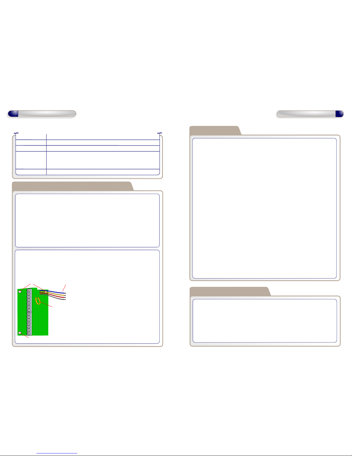
To enrol the expander:
In the installer menu navigate to System -
Installation wizards - Enrol Expander
When enrolled the expander zones will
appear after zone 72 in the Devices/Zones
menu.
Change individual siren options.
1.
2.
Configure Sirens ( optional )
Select a siren menu: in the installer menu navigate to Sirens - <desired
siren> and then press OK.
Change the siren's Name, Area, Volume, Sounds and LED Heartbeat as
required.
Select the add users menu: in the installer menu navigate to Users - Add
user and then press OK.
Select the user number to add and press OK.
Enter the new code for the user and press OK.
Re-enter the same new code for the user and press OK. Set the other
options as prompted.
Select the delete users menu: in the installer menu navigate to Users -
Delete user and then press OK.
Select the user to delete and press OK.
Select Yes to confirm and press OK.
Select a user menu: in the installer menu navigate to Users - <desired user>
and then press OK.
Change the user's Name, Code, Accessible Areas and Permissions as
required.
Configure Users
Add a user
1.
2.
3.
4.
Delete a user
1.
2.
3.
Set user codes and operations
1.
2.
LF alarm
FTC
Exit terminator
Off
Indicates an external dialler Line Fault. Always causes an alarm
whether its area is set or unset.
Indicates an external dialler Failure To Communicate.
If an area has an exit terminator zone then the exit period when
setting does not end with an exit timer. Instead it ends when the
exit terminator zone it activated.
This zone does nothing.
Set global options for Onboard EOL type for wired zones 71 & 72 of i7/70
panel.
1.
2.
Configure Wired Zones
Select an area menu: in the installer menu navigate to Devices/Zones Global Settings - Onboard EOl types and then press OK.
Change the EOL type for all wired zones as required.
If using single EOl or no EOL, configure zone 71 or zone 72 as Zone Type
Tamper.
mount hole
mount hole
External
tamper
loop
connections
to
panel
A
B
V+
V-
Z1
GND
Z2
GND
Z3
GND
Z4
GND
Z5
GND
OP1
OP2
GND
V+
To enrol the expander:
In the installer menu navigate to System - Installation wizards - Enrol Expander
The panel will display the message “Expander enrolled” and the expander LED
starts flashing.
When enrolled the expander zones will
appear after zone 72 in the
Devices/Zones menu
eg.: zone 73, 74 etc.
20
Operation Instructions
21
Operation Instructions
 Loading...